EP4091927A2 - Ordre d'appariement attribuable - Google Patents
Ordre d'appariement attribuable Download PDFInfo
- Publication number
- EP4091927A2 EP4091927A2 EP22174618.3A EP22174618A EP4091927A2 EP 4091927 A2 EP4091927 A2 EP 4091927A2 EP 22174618 A EP22174618 A EP 22174618A EP 4091927 A2 EP4091927 A2 EP 4091927A2
- Authority
- EP
- European Patent Office
- Prior art keywords
- controller
- devices
- pairing
- controller devices
- assignable
- Prior art date
- Legal status (The legal status is an assumption and is not a legal conclusion. Google has not performed a legal analysis and makes no representation as to the accuracy of the status listed.)
- Pending
Links
Images


Classifications
-
- B—PERFORMING OPERATIONS; TRANSPORTING
- B62—LAND VEHICLES FOR TRAVELLING OTHERWISE THAN ON RAILS
- B62K—CYCLES; CYCLE FRAMES; CYCLE STEERING DEVICES; RIDER-OPERATED TERMINAL CONTROLS SPECIALLY ADAPTED FOR CYCLES; CYCLE AXLE SUSPENSIONS; CYCLE SIDE-CARS, FORECARS, OR THE LIKE
- B62K3/00—Bicycles
-
- B—PERFORMING OPERATIONS; TRANSPORTING
- B62—LAND VEHICLES FOR TRAVELLING OTHERWISE THAN ON RAILS
- B62M—RIDER PROPULSION OF WHEELED VEHICLES OR SLEDGES; POWERED PROPULSION OF SLEDGES OR SINGLE-TRACK CYCLES; TRANSMISSIONS SPECIALLY ADAPTED FOR SUCH VEHICLES
- B62M9/00—Transmissions characterised by use of an endless chain, belt, or the like
- B62M9/04—Transmissions characterised by use of an endless chain, belt, or the like of changeable ratio
- B62M9/06—Transmissions characterised by use of an endless chain, belt, or the like of changeable ratio using a single chain, belt, or the like
- B62M9/10—Transmissions characterised by use of an endless chain, belt, or the like of changeable ratio using a single chain, belt, or the like involving different-sized wheels, e.g. rear sprocket chain wheels selectively engaged by the chain, belt, or the like
- B62M9/12—Transmissions characterised by use of an endless chain, belt, or the like of changeable ratio using a single chain, belt, or the like involving different-sized wheels, e.g. rear sprocket chain wheels selectively engaged by the chain, belt, or the like the chain, belt, or the like being laterally shiftable, e.g. using a rear derailleur
- B62M9/121—Rear derailleurs
- B62M9/122—Rear derailleurs electrically or fluid actuated; Controls thereof
-
- B—PERFORMING OPERATIONS; TRANSPORTING
- B60—VEHICLES IN GENERAL
- B60R—VEHICLES, VEHICLE FITTINGS, OR VEHICLE PARTS, NOT OTHERWISE PROVIDED FOR
- B60R16/00—Electric or fluid circuits specially adapted for vehicles and not otherwise provided for; Arrangement of elements of electric or fluid circuits specially adapted for vehicles and not otherwise provided for
- B60R16/02—Electric or fluid circuits specially adapted for vehicles and not otherwise provided for; Arrangement of elements of electric or fluid circuits specially adapted for vehicles and not otherwise provided for electric constitutive elements
- B60R16/023—Electric or fluid circuits specially adapted for vehicles and not otherwise provided for; Arrangement of elements of electric or fluid circuits specially adapted for vehicles and not otherwise provided for electric constitutive elements for transmission of signals between vehicle parts or subsystems
- B60R16/027—Electric or fluid circuits specially adapted for vehicles and not otherwise provided for; Arrangement of elements of electric or fluid circuits specially adapted for vehicles and not otherwise provided for electric constitutive elements for transmission of signals between vehicle parts or subsystems between relatively movable parts of the vehicle, e.g. between steering wheel and column
-
- B—PERFORMING OPERATIONS; TRANSPORTING
- B62—LAND VEHICLES FOR TRAVELLING OTHERWISE THAN ON RAILS
- B62J—CYCLE SADDLES OR SEATS; AUXILIARY DEVICES OR ACCESSORIES SPECIALLY ADAPTED TO CYCLES AND NOT OTHERWISE PROVIDED FOR, e.g. ARTICLE CARRIERS OR CYCLE PROTECTORS
- B62J45/00—Electrical equipment arrangements specially adapted for use as accessories on cycles, not otherwise provided for
-
- B—PERFORMING OPERATIONS; TRANSPORTING
- B62—LAND VEHICLES FOR TRAVELLING OTHERWISE THAN ON RAILS
- B62K—CYCLES; CYCLE FRAMES; CYCLE STEERING DEVICES; RIDER-OPERATED TERMINAL CONTROLS SPECIALLY ADAPTED FOR CYCLES; CYCLE AXLE SUSPENSIONS; CYCLE SIDE-CARS, FORECARS, OR THE LIKE
- B62K23/00—Rider-operated controls specially adapted for cycles, i.e. means for initiating control operations, e.g. levers, grips
- B62K23/02—Rider-operated controls specially adapted for cycles, i.e. means for initiating control operations, e.g. levers, grips hand actuated
-
- B—PERFORMING OPERATIONS; TRANSPORTING
- B62—LAND VEHICLES FOR TRAVELLING OTHERWISE THAN ON RAILS
- B62K—CYCLES; CYCLE FRAMES; CYCLE STEERING DEVICES; RIDER-OPERATED TERMINAL CONTROLS SPECIALLY ADAPTED FOR CYCLES; CYCLE AXLE SUSPENSIONS; CYCLE SIDE-CARS, FORECARS, OR THE LIKE
- B62K3/00—Bicycles
- B62K3/02—Frames
-
- B—PERFORMING OPERATIONS; TRANSPORTING
- B62—LAND VEHICLES FOR TRAVELLING OTHERWISE THAN ON RAILS
- B62L—BRAKES SPECIALLY ADAPTED FOR CYCLES
- B62L3/00—Brake-actuating mechanisms; Arrangements thereof
- B62L3/02—Brake-actuating mechanisms; Arrangements thereof for control by a hand lever
-
- B—PERFORMING OPERATIONS; TRANSPORTING
- B62—LAND VEHICLES FOR TRAVELLING OTHERWISE THAN ON RAILS
- B62M—RIDER PROPULSION OF WHEELED VEHICLES OR SLEDGES; POWERED PROPULSION OF SLEDGES OR SINGLE-TRACK CYCLES; TRANSMISSIONS SPECIALLY ADAPTED FOR SUCH VEHICLES
- B62M25/00—Actuators for gearing speed-change mechanisms specially adapted for cycles
- B62M25/08—Actuators for gearing speed-change mechanisms specially adapted for cycles with electrical or fluid transmitting systems
-
- B—PERFORMING OPERATIONS; TRANSPORTING
- B62—LAND VEHICLES FOR TRAVELLING OTHERWISE THAN ON RAILS
- B62M—RIDER PROPULSION OF WHEELED VEHICLES OR SLEDGES; POWERED PROPULSION OF SLEDGES OR SINGLE-TRACK CYCLES; TRANSMISSIONS SPECIALLY ADAPTED FOR SUCH VEHICLES
- B62M9/00—Transmissions characterised by use of an endless chain, belt, or the like
- B62M9/04—Transmissions characterised by use of an endless chain, belt, or the like of changeable ratio
- B62M9/06—Transmissions characterised by use of an endless chain, belt, or the like of changeable ratio using a single chain, belt, or the like
- B62M9/10—Transmissions characterised by use of an endless chain, belt, or the like of changeable ratio using a single chain, belt, or the like involving different-sized wheels, e.g. rear sprocket chain wheels selectively engaged by the chain, belt, or the like
- B62M9/12—Transmissions characterised by use of an endless chain, belt, or the like of changeable ratio using a single chain, belt, or the like involving different-sized wheels, e.g. rear sprocket chain wheels selectively engaged by the chain, belt, or the like the chain, belt, or the like being laterally shiftable, e.g. using a rear derailleur
- B62M9/121—Rear derailleurs
- B62M9/126—Chain guides; Mounting thereof
-
- B—PERFORMING OPERATIONS; TRANSPORTING
- B62—LAND VEHICLES FOR TRAVELLING OTHERWISE THAN ON RAILS
- B62M—RIDER PROPULSION OF WHEELED VEHICLES OR SLEDGES; POWERED PROPULSION OF SLEDGES OR SINGLE-TRACK CYCLES; TRANSMISSIONS SPECIALLY ADAPTED FOR SUCH VEHICLES
- B62M9/00—Transmissions characterised by use of an endless chain, belt, or the like
- B62M9/04—Transmissions characterised by use of an endless chain, belt, or the like of changeable ratio
- B62M9/06—Transmissions characterised by use of an endless chain, belt, or the like of changeable ratio using a single chain, belt, or the like
- B62M9/10—Transmissions characterised by use of an endless chain, belt, or the like of changeable ratio using a single chain, belt, or the like involving different-sized wheels, e.g. rear sprocket chain wheels selectively engaged by the chain, belt, or the like
- B62M9/12—Transmissions characterised by use of an endless chain, belt, or the like of changeable ratio using a single chain, belt, or the like involving different-sized wheels, e.g. rear sprocket chain wheels selectively engaged by the chain, belt, or the like the chain, belt, or the like being laterally shiftable, e.g. using a rear derailleur
- B62M9/131—Front derailleurs
- B62M9/132—Front derailleurs electrically or fluid actuated; Controls thereof
-
- G—PHYSICS
- G08—SIGNALLING
- G08C—TRANSMISSION SYSTEMS FOR MEASURED VALUES, CONTROL OR SIMILAR SIGNALS
- G08C17/00—Arrangements for transmitting signals characterised by the use of a wireless electrical link
- G08C17/02—Arrangements for transmitting signals characterised by the use of a wireless electrical link using a radio link
-
- H—ELECTRICITY
- H04—ELECTRIC COMMUNICATION TECHNIQUE
- H04L—TRANSMISSION OF DIGITAL INFORMATION, e.g. TELEGRAPHIC COMMUNICATION
- H04L67/00—Network arrangements or protocols for supporting network services or applications
- H04L67/01—Protocols
- H04L67/12—Protocols specially adapted for proprietary or special-purpose networking environments, e.g. medical networks, sensor networks, networks in vehicles or remote metering networks
-
- B—PERFORMING OPERATIONS; TRANSPORTING
- B62—LAND VEHICLES FOR TRAVELLING OTHERWISE THAN ON RAILS
- B62J—CYCLE SADDLES OR SEATS; AUXILIARY DEVICES OR ACCESSORIES SPECIALLY ADAPTED TO CYCLES AND NOT OTHERWISE PROVIDED FOR, e.g. ARTICLE CARRIERS OR CYCLE PROTECTORS
- B62J1/00—Saddles or other seats for cycles; Arrangement thereof; Component parts
- B62J1/08—Frames for saddles; Connections between saddle frames and seat pillars; Seat pillars
- B62J2001/085—Seat pillars having mechanisms to vary seat height, independently of the cycle frame
Definitions
- a bicycle includes various components that allow a user to control the operation of the bicycle.
- the bicycle may include a drivetrain where one or more gears can be selectably engaged with a drive chain to modify pedaling cadence and resistance.
- the bicycle may include controller devices that receive input from the user to cause the drive chain to engage different gears.
- a system for a bicycle includes a plurality of controller devices.
- a type of controller device is the same for two or more controller devices of the plurality of controller devices.
- the system also includes a pairing coordinator device configured to receive a respective device type identification from each controller device of the plurality of controller devices, and identify the type of controller device for the two or more controller devices based on the received device type identifications for the two or more controller devices, respectively.
- the pairing coordinator device is further configured to update the device type identifications for the two or more controller devices, respectively, such that the updated device type identifications for the two or more controller devices are different than each other.
- the pairing coordinator device is further configured to pair only controller devices of the plurality of controller devices having different respective device type identifications with the pairing coordinator device, such that a wireless network that enables communications between the pairing coordinator device and the controller devices is established.
- the system further includes one or more movable components.
- Each movable component of the one or more movable components is configured to enact at least one respective operation on the bicycle.
- the pairing coordinator device is further configured to receive a respective device type identification from each moveable component of the one or more movable components, and pair the one or more movable components to the wireless network, such that the wireless network enables communications between the pairing coordinator device, the controller devices, and the one or more movable components.
- the pairing coordinator device is further configured to generate a roster and transmit the roster to the one or more movable components via the wireless network.
- the roster identifies the controller devices and the one or more movable components paired to the wireless network.
- each controller device of the plurality of controller devices includes at least one respective input element.
- the paired controller devices are configured to transmit signals indicating input received by the input elements of the paired controller devices, respectively.
- the one or more movable components are configured to identify, based on the roster received from the pairing coordinator device, operations to be executed, respectively, in response to the signals received from the paired controller devices.
- the paired one or more movable components are configured to determine which of the one or more movable components are to execute which of the operations responsive to the signals.
- the determination of which of the one or more movable components are to execute which of the operations responsive to the signals includes process of a default set of assignments.
- a movable component of the paired one or more movable components is further configured to receive, via the wireless network, the signals from the paired controller devices, identify one of the received signals as being from an assigned controller device of the paired controller devices according to the default set of assignments, and enact the respective operation in response to the one received signal from the assigned controller device.
- the pairing coordinator device includes a communication interface configured to receive a modified set of assignments.
- the modified set of assignments causes at least one of the operations to be enacted by a corresponding movable component of the one or more movable components in response to one or more of the signals from a different one of the controller devices compared to the default set of assignments.
- the pairing coordinator device is configured to transmit, via the wireless network, the modified set of assignments to the one or more movable components.
- the one or more movable components are configured to replace the default set of assignments with the modified set of assignments, and determine how the one or more movable devices enact the operations responsive to the signals according to the modified set of assignments.
- the pairing coordinator device is a movable component of the one or more movable components.
- the one or more movable components include a front derailleur configured to modify a position of a bicycle chain of the bicycle relative to a first set of gears of the bicycle, a rear derailleur configured to modify a position of the bicycle chain relative to a second set of gears of the bicycle, a seat post assembly configured to modify a position of a seat of the bicycle relative to a frame of the bicycle, or any combination thereof.
- the device type identifications are updated based on a temporal order in which the respective device type identifications are received by the pairing coordinator from the two or more controller devices.
- the identification of the type of controller device for the two or more controller devices includes comparison of the received respective device type identifications for the two or more controller devices to a predetermined device type identification or a predetermined device type identification range, respectively, and identification of the type of controller device when the received respective device type identifications for the two or more controller devices are the same as the predetermined device type identification or within the predetermined device identification range.
- the received respective device type identifications have numerical values
- the predetermined device type identification has a numerical value
- the predetermined device type identification range represents a range of numerical values
- the type of controller device is a first type of controller device.
- the plurality of controller devices include two or more second controller devices.
- the two or more second controller devices are a second type of controller device.
- the second type of controller device is different than the first type of controller device.
- the first type of controller device is one of an assignable single button controller and an assignable two button controller
- the second type of controller device is the other of the assignable single button controller and the assignable two button controller
- the pairing coordinator device is further configured to receive a respective device type identification from each second controller device of the plurality of second controller devices.
- the pairing coordinator device is further configured to identify the second type of controller device for the plurality of second controller devices based on the device type identifications received from the plurality of second controller devices. Based on the identification of the second type of controller device, the pairing coordinator device is further configured to update the device type identifications for the plurality of second controller devices, respectively, such that the updated device type identifications for the plurality of second controller devices are different than each other.
- the pairing coordinator device is further configured to pair only second controller devices having different respective device type identifications, respectively, to the wireless network, such that the wireless network enables communications between the pairing coordinator device, the first controller devices, and the second controller devices.
- the update of the device type identifications for the two or more controller devices includes storage of the updated device type identifications at the two or more controller devices, respectively.
- a pairing coordinator device for a bicycle includes a communication interface configured to communicate with a plurality of controller devices.
- a type of controller device is the same for two or more controller devices of the plurality of controller devices.
- the communication interface is configured to receive a respective device type identification from each controller device of the plurality of controller device.
- the pairing coordinator device further includes one or more processors in communication with the communication interface.
- the one or more processors are configured to establish, via the communication interface, a pairing session that allows the plurality of controller devices to be paired to a wireless network.
- the establishment of the pairing session includes identification of the type of controller device for the two or more controller devices based on the received device type identifications for the two or more controller devices, respectively.
- the establishment of the pairing session further includes update of the device type identifications for the two or more controller devices, respectively, such that the updated device type identifications for the two or more controller devices are different than each other.
- the establishment of the pairing session further includes pair of only controller devices of the plurality of controller devices having different respective device type identifications with the pairing coordinator device, such that the wireless network, which enables communications between at least the pairing coordinator device and the controller devices, is established.
- the device type identifications are updated based on a temporal order in which the respective device type identifications are received by the pairing coordinator from the two or more controller devices.
- the pairing session is a first pairing session
- the wireless network is a first wireless network
- the temporal order is a first temporal order
- the updated device type identifications are first updated device type identifications.
- the one or more processors are further configured to establish, via the communication interface, a second pairing session that allows the plurality of controller devices to be paired to a second wireless network.
- the establishment of the second pairing session is after the establishment of the first pairing session.
- the establishment of the second pairing session includes receipt, via the communication interface, of a respective device type identification from each controller device of the plurality of controller devices in a second temporal order.
- the second temporal order is different than the first temporal order.
- the establishment of the second pairing session further includes identification of the type of controller device for the two or more controller devices based on the received device type identifications for the two or more controller devices, respectively, and based on the identification of the type of controller device, update of the first updated device type identifications for the two or more controller devices, respectively, such that second updated device type identifications are generated for the two or more controller devices, respectively.
- the second updated device type identifications are different than the first updated device type identifications.
- the establishment of the second pairing session further includes pair of only controller devices of the plurality of controller devices having different respective device type identifications with the pairing coordinator device, such that the second wireless network, which enables communications between at least the pairing coordinator device and the controller devices, is established.
- a controller device for a bicycle includes an input element configured to receive input from a user of the bicycle.
- the controller device further includes a communication interface in communication with the input element.
- the communication interface is configured to communicate wirelessly with a pairing coordinator device of the bicycle and one or more movable components of the bicycle.
- the controller device further includes a memory in communication with the communication interface.
- the memory is configured to store an assignable device type identification.
- the assignable device type identification identifies the controller device as an assignable controller device.
- the controller device further includes one or more processors in communication with the memory and the communication interface, the one or more processors are configured, after initiation of a pairing session by the pairing coordinator device, to transmit, via the communication interface, the assignable device type identification to the pairing coordinator device.
- the one or more processors are further configured to receive, via the communication interface, a new device type identification from the pairing coordinator device.
- the new device type identification is different than the assignable device type identification.
- the one or more processors are further configured to store, by the memory, the new device type identification, and pair the controller device to a wireless network established by the pairing coordinator device based on the new device type identification.
- the wireless network enables communications between the controller device, the pairing coordinator device, and the one or more movable components.
- the one or more processors are configured to generate a signal in response to the received input from the user of the bicycle at the input element, and transmit, via the communication interface and the wireless network, the generated signal to the one or more movable components.
- embodiments provide systems, devices, and methods for controlling components on a bicycle.
- the embodiments employ a plurality of controller devices that receive input from a user to control operation-enacting devices on the bicycle.
- Operation-enacting devices generally include at least one movable component configured to modify an operative state of the bicycle.
- the controller devices and the operation-enacting devices are paired to a wireless network.
- a particular controller device receives an input from the user, the particular controller device sends a corresponding signal to the operation-enacting devices paired to the network.
- Embodiments employ a set of assignments to determine which, if any, of the operation-enacting devices responds to the signal from the particular controller device.
- the set of assignments may be modified by the user according to preferences of the user.
- the embodiments provide a reconfigurable control system for the components of the bicycle.
- each type of bicycle component may be paired into a wireless network (e.g., a system) of the bicycle at a given time.
- a wireless network e.g., a system
- Each component has a unique device type, and if a pairing with multiple components of a same type is attempted, only one of the components will be functional.
- assignable controllers provide that all components on the bicycle may not be unique.
- Multiple assignable controllers may be added to a bicycle according to a preference of a rider. For example, two identical shifters may be used for a left shifter and a right shifter, respectively, instead of a unique left shifter and a unique right shifter. Accordingly, a number of identical components may be paired into the system.
- each assignable controller may be differentiated from the other assignable controllers.
- Each assignable controller may be differentiated from the other assignable controllers based on, for example, an order in which the assignable controllers are paired into the system.
- Each assignable controller has a different default reaction and is able to be configured individually.
- each of the assignable controllers may have a dynamic device type assigned to the respective assignable controller upon pairing.
- Each of the assignable controllers is programmed with an assignable device type at or after manufacture.
- the pairing coordinator device inspects the programmed device type to determine whether the programmed device type is an assignable device type. If the programmed device type is an assignable device type, the pairing coordinator device programs the respective assignable controller with a new device type.
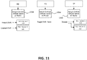
- the new device type is assigned (e.g., in increasing numerical order) based on the assignable device type (e.g., a single button controller or a two button controller) and the order in which the assignable controllers are paired into the system.
- the pairing coordinator device uses a roster to designate default reactions.
- the default reactions are mapped to the assignable device types. For example, a first of the assignable controllers, which is paired first into the system, has a default reaction of an outboard shift of a rear derailleur of the bicycle, and a second of the assignable controllers, which is paired into the system immediately after the first assignable controller, has a default reaction of an inboard shift of the rear derailleur.
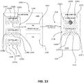
- All controllers of the bicycle that are paired into the system may be reconfigured using, for example, a mobile device application.
- a mobile device application When the user opens the mobile device application, the user may see representations of multiple controllers that communicate within the system of the bicycle, including representations of the assignable controllers and representations of non-assignable (e.g., standard) controllers paired into the system.
- Each representation of a standard controller within the system has a unique appearance (e.g., name and/or artwork), such that the user may easily identify the component (e.g., rear derailleur, front derailleur) being configured within, for example, the mobile device application.
- the representations of the assignable controllers within the mobile device application may not clearly indicate which of the assignable controllers corresponds to which of the representations within the mobile device application.
- the user when the user opens the mobile device application, the user may see representations of four devices. While the two standard controllers are identifiable by corresponding unique representations, the user may not be able to identify which assignable controller corresponds to which representation or icon within the mobile device application.
- the present embodiments provide a method in which correspondence between assignable controllers on the bicycle and representations within the mobile device application may be determined.
- the user may interact with an input device (e.g., a button) on the respective assignable controller, and the corresponding representation within the mobile device application is highlighted within the mobile device application in response to the user interaction with the respective assignable controller.
- an input device e.g., a button
- the respective assignable controller When the user interacts with the input device of the respective assignable controller (e.g., presses the button of the respective assignable controller), the respective assignable controller sends a device type and a button mask of the respective assignable controller to all receivers of the system. For example, the respective assignable controller sends a button message including the device type and the button mask of the respective assignable controller to a bridge device of the bicycle in response to the button press.
- the bridge device caches the device type and the button mask of the respective assignable controller.
- the bridge device transmits a notification to the mobile device application. That notification identifies that a new controller has sent a button message.
- the mobile device application queries the bridge device for information about the new controller (e.g., the respective assignable controller).
- the bridge device In response to the query, the bridge device sends the cached device type and the button mask corresponding to the respective assignable controller to the mobile device application.
- the mobile device application highlights (e.g., lights up) the representation displayed within the mobile device application based on the device type and the button mask received from the bridge device.
- the disclosed bicycle component control differentiates identical components on a bicycle (e.g., shifters) and allows for the assignment of default reactions. This assignment of default reactions may make user interaction with a mobile device application unnecessary during bicycle system set-up. Further, the user is able to easily identify identical components within the mobile device application, for example, by interacting with buttons on the components; the user may then configure controls, check battery status, and perform maintenance without having to guess which controller corresponds to which representation within the mobile device application.
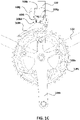
- FIG. 1A illustrates a right side view of an example road bicycle 100.
- the bicycle 100 includes a frame 102, a front wheel 104, a rear wheel 106, and a drivetrain 108.
- the front wheel 104 and the rear wheel 106 are rotatably coupled to the frame 102.
- the bicycle includes a front brake 110 for braking the front wheel 104 and a rear brake 112 for braking the rear wheel 106.
- the bicycle 100 includes a handlebar assembly 114 attached to the frame 102.
- FIG. 1B illustrates a schematic diagram depicting the handlebar assembly 114 and other components coupled to the handlebar assembly 114.
- the handlebar assembly 114 includes a right drop bar 114a and a left drop bar 114b to accommodate the right hand and the left hand of the user, respectively.
- the bicycle 100 includes a first or right controller device 120 coupled to the right drop bar 114a.
- the first controller device 120 includes a first or right brake lever 116 to allow the user to operate the rear brake 112.
- the bicycle 100 includes a second or left controller device 122 coupled to the left drop bar 114b.
- the second controller device 122 includes a second or left brake lever 118 to allow the user to operate the front brake 110.
- the first control device 120 and the second control device 122 may be identical control devices (e.g., interchangeable, assignable control devices).
- the drivetrain 108 includes a drive chain 108a, a front crank 108b, front chainrings 108c, a front gear changer such as an electromechanical front derailleur 108d, rear sprockets 108e, and a rear gear changer such as an electromechanical rear derailleur 108f.
- the front chainrings 108c are coupled to the front crank 108b.
- the diameters and number of teeth on the front sprockets 108c may differ from each other.
- the rear sprockets 108e are coaxially mounted to the rear wheel 106.
- the diameters and the numbers of teeth on the rear sprockets 108e may gradually decrease from left to right (e.g., relative to the frame 102 such that a smallest of the sprockets 108 is outermost relative to the frame 102).
- the diameters and the numbers of teeth on the rear sprockets 108e may gradually decrease from right to left (e.g., relative to the frame 102).
- the chain 108a engages a selected chainring 108c and a selected sprocket 108e.
- the user can pedal to rotate the front crank 108b relative to the frame 102.
- Rotation of the front crank 108b causes the selected chainring 108c to rotate and the chain 108a to move through the drivetrain 108.
- Movement of the chain 108a causes corresponding rotation of the selected sprocket 108e and thus the rear wheel 106.
- Rotation of the rear wheel 106 against the ground may propel the bicycle 100 in a forward direction.
- the front and/or forward orientation and movement of the bicycle 100 is indicated by the direction of arrow "A.”
- other terms relating to direction may be used herein. For example, the terms “inboard” and “outboard,” and “left” and “right” may be used.
- the selected chainring 108c and the selected sprocket 108e determine a gear ratio for driving the bicycle 100.
- Operation of the front derailleur 108d allows the user to change the selected chainring 108c engaged by the chain 108a.
- the front derailleur 108d may be actuated to shift the chain 108a left or right from one chainring 108c to the other.
- the front derailleur 108d is shown as a wireless electrically-actuated front derailleur mounted to the frame 102.
- the front derailleur 108d may include a base member 108g mounted to the frame 102 of the bicycle 100 and a chain guide assembly 108h or cage movably connected to the base member 108g by a front linkage 108i in the form of, for example, a parallelogram.
- a front power supply108j (e.g., a removable battery) may be mounted on the front derailleur 108d.
- the front power supply 108j may supply power to a front motor unit 108k.
- the front motor unit 108k is configured to supply torque to the components of the front derailleur 108d to move the chain guide assembly 108h relative to the front base member 108g such that the front derailleur 108d may shift the chain 108a between the front sprockets 108c.
- the rear derailleur 108f allows the user to change the selected sprocket 108e engaged by the chain 108a.
- the rear derailleur 108f may be actuated to shift the chain 108a left or right from one sprocket 108e to another.
- the rear derailleur 108f is shown as a wireless electrically-actuated rear derailleur mounted to the frame 102.
- the rear derailleur may include a base member 108I (e.g., a b-knuckle) that is mounted to the frame 102 of the bicycle 100.
- a linkage 108m may include two links 108n that are pivotally connected to the base member 1081.
- a movable member 108o (e.g., a p-knuckle) may be connected to the linkage 108m.
- a chain guide assembly 108q or cage may be configured to engage and maintain tension in the chain 108a and may be pivotally connected to a part of the movable member 108o.
- a motor unit 108r and rear power supply 108s are disposed on the rear derailleur 108f.
- the rear power supply 108s supplies power to the motor unit 108r.
- the motor unit 108r is disposed in the movable member 108o.
- the motor unit 108r may be disposed in one of the links 108n or in the base member 1081.
- the motor unit 108r may include a motor and a gear transmission.
- the motor unit 108r may be coupled with the linkage 108m to laterally move the cage 108q and thus shift the chain 108a among the rear sprockets 108e.
- the first controller device 120 and the second controller device 122 include a first electrical switch 120c and a second electrical switch 122c that are actuated by a first input element and a second input element (e.g., a first shift lever 120a and a second shift lever 122a), respectively.
- the first shift lever 120a is configured to receive a right input from the right hand of the user and actuate the first electrical switch 120c.
- the second shift lever 122a configured to receive a left input from the left hand of the user and actuate the second electrical switch 122c.
- the first shift lever 120a may be positioned behind the first brake lever 116, while the second shift lever 122a may be positioned behind the second brake lever 118.
- the user may manually apply pressure on the right side of the first shift lever 120a.
- the first shift lever 120a may pivot about a first shift lever axis L1 from an initial rest position to a shift actuation position.
- the first shift lever 120a may be biased with a spring or the like so that when the manual pressure is no longer applied by the user, the first shift lever 120a returns to the initial rest position.
- the user may manually apply pressure on the left side of the second shift lever 122a.
- the second shift lever 122a may pivot about a second shift lever axis L2 (not shown) from an initial rest position to a shift actuation position.
- the second shift lever 122a may be biased with a spring or the like so that when the manual pressure is no longer applied by the user, the second shift lever 122a returns to the left starting position.
- the first controller device 120 and the second controller device 122 include a first controller processor 120e and a second controller processor 122e, respectively.
- the first controller processor 120e and the second controller processor 122e electronically process the manual input received by the first shift lever 120a and the second shift lever 122a, respectively.
- the right input triggers a first controller communication interface 120d to wirelessly send a first shift signal 120b
- left input triggers a second controller communication interface 122d to wirelessly send a second shift signal 122b.
- the front derailleur 108d and the rear derailleur 108f include communication interfaces and processors that are configured to receive and electronically process the first shift signal 120b and/or the second shift signal 122b to determine a designated response.
- the user provides the right input via the first shift lever 120a but does not provide the left input via the second shift lever 122a.
- the first controller device 120 sends the first shift signal 120b, while the left controller device 122 sends no signal.
- the rear derailleur 108f receives the first shift signal 120b with no second shift signal 122b
- the rear derailleur 108f shifts the chain 108a to engage the next smaller sprocket 108e to the right or performs a downshift.
- the front derailleur 108d receives the first shift signal 120b with no second shift signal 122b
- the front derailleur 108d remains idle.
- the user provides the left input via the second shift lever 122a but does not provide the right input via the right shift lever 120a.
- the second controller device 122 sends the second shift signal 122b, while the first controller device 120 sends no signal.
- the rear derailleur 108f receives the second shift signal 122b with no first shift signal 120b
- the rear derailleur 108f shifts the chain 108a to engage the next larger sprocket 108e to the left or performs a upshift.
- the front derailleur 108d receives the second shift signal 122b with no second shift signal 120b, the front derailleur 108d remains idle.
- the user simultaneously provides the right input via the first shift lever 120a and the left input via the second shift lever 122a.
- the first controller device 120 sends the first shift signal 120b
- the second controller device 122 sends the second shift signal 122b.
- the rear derailleur 108f receives the first shift signal 120b and the second shift signal 122b simultaneously or within a certain time period
- the rear derailleur 108f remains idle.
- the front derailleur 108d receives the first shift signal 120b and the second shift signal 122b simultaneously or within a certain time period
- the front derailleur 108d shifts the chain 108a left or right to engage a different chainring 108c.
- the drivetrain 108 includes only two chainrings 108c, so the simultaneous right input and left input causes the chain 108a to alternate between the two chainrings 108c. Other configurations may be provided.
- the user may manually apply pressure to the first shift lever 120a and/or the second shift lever 122a for varying amounts of time. For example, without applying pressure to the second shift lever 122a, the user may apply continuous pressure to keep the first shift lever 120a in the left final position for a period that exceeds a threshold amount of time (e.g., approximately one second).
- a threshold amount of time e.g., approximately one second.
- the first controller device 120 sends the first shift signal 120b for a corresponding amount of time (e.g., until the user releases the pressure on the first shift lever 120a).
- the rear derailleur 108f receives the first shift signal 120b, the rear derailleur 108f determines that the first shift signal 120b exceeds a threshold amount of time.
- the rear derailleur 108f shifts the chain 108a repeatedly over multiple sprockets 108e to the right until the user releases the pressure on the first shift lever 120a and the first shift signal 120b ceases, or until the chain 108a reaches the right-most sprocket 108e.
- the user may apply continuous pressure to the left shift lever 122a for a period that exceeds the threshold amount of time.
- the first controller device 120 and the second controller device 122 employ the first shift lever 120a and the second shift lever 122a as respective input elements to generate corresponding wireless shift signals 120b, 122b to actuate the front derailleur 108d and the rear derailleur 108f.
- Alternative embodiments may include controller devices with different configurations to control a front derailleur and/or a rear derailleur.
- a bicycle may include aerobars with pushbuttons instead of drop bars with shift levers, where the pushbuttons act as input elements that may be pressed by the user to generate wireless signals that may be received and processed by the front derailleur and the rear derailleur.
- controller devices may be coupled to handlebar assemblies, other controller devices may be coupled to other areas of a bicycle, such as locations throughout a frame of the bicycle. Further, other types of controller devices may be provided.
- a unified shifter device may be employed, where the user may press one or more pushbuttons on a mounted box to send signals that control the front derailleur and/or the rear derailleur.
- a pedal sensor may be employed to receive input from the user via the pedaling action of the user, and the front derailleur and/or the rear derailleur may respond to a signal from the pedal sensor (e.g., select gears to maintain a desired cadence or pedal resistance).
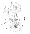
- FIG. 2A illustrates a right side view of an example mountain bicycle 200.
- the bicycle 200 includes a frame 202, a front wheel 204, a rear wheel 206, a drivetrain 208, front disk brakes 210, and rear disk brakes 212.
- the drivetrain 208 includes a chain 208a, a front crank 208b, a front chainring 208c, rear sprockets 208e, and a rear derailleur 208f, which operate in a manner similar to the corresponding components of the drivetrain 108 above.
- the bicycle 200 includes other operating-enacting devices such as a seat post assembly 226 (e.g., a heigh-adjustable seat post assembly), a front suspension system 230, and a rear suspension system 232.
- a seat post assembly 226 e.g., a heigh-adjustable seat post assembly
- the seat post assembly 226 is shown as a wireless, electrically-actuated seat post assembly 226 that allows a position of a seat 228 to be dynamically adjusted.
- the adjustable seat post assembly 226 may include an operable valve (not shown) that allows the seat 228 to be dropped to a lower height during a ride to change a position of the user relative to the frame 202 and achieve better handling.
- the seat post assembly 226 includes a first or lower tube 226a and a second or upper tube 226b (e.g., two tubes).
- the two tubes 226a, 226b are movable relative to each other to establish a height of the seat 228 relative to the frame 202.
- a head 226c is fixed to a top of the second tube 226b.
- a seat post motor unit 226d is mounted to the head 226c, and a power supply 226e (e.g., a removable battery) is attached to the motor unit 226d.
- the motor unit 226d may include a motor and a gear transmission.
- the power supply 226e may supply power to the seat post motor unit 226d.
- the seat post motor unit 226d is configured to supply torque to the components of the seat post assembly 226 to open and close the operable valve.
- the front suspension system 230 is shown as a wireless, electrically-actuated front suspension system that allows suspension characteristics at the front wheel 204 to be dynamically adjusted.
- the rear suspension system 232 is shown as a wireless, electrically-actuated rear suspension system that allows suspension characteristics at the rear wheel 206 to be dynamically adjusted.
- the front suspension system 230 and the rear suspension system 232 may further include power supplies such as batteries that supply power to a front suspension motor unit and a rear suspension motor unit (e.g., motor units), respectively.
- the motor units may be configured to supply torque to components of the front suspension system 230 and the rear suspension system 232, respectively, to open and close one or more valves to change various suspension characteristics.
- the bicycle 200 includes a first or right controller device 220 and a second or left controller device 222.
- the first controller device 220 and the second controller device 222 are identical controller devices (e.g., assignable controllers).
- the first controller device 220 and the second controller device 222 include a first electrical switch 220c and a second electrical switch 222c that are actuated by a first input element and a second input element (e.g., a first shift lever 220a and a second shift lever 222a), respectively.
- the handlebar assembly 214 includes a flat bar or a riser bar instead of drop bars.
- the first controller device 220 is coupled to a right side of the flat or riser bar
- the second controller device 222 is coupled to a left side of the flat or riser bar.
- the bicycle 200 may include a seat post controller device 234, a front suspension controller device 236, and a rear suspension controller device 238 coupled to the handlebar assembly 214.
- the user may operate the first shift lever 220a and/or the second shift lever 222a as described above to generate a first shift signal 220b and/or a second shift signal 222b, respectively. Similar to the bicycle 100, the first shift signal 220b and/or the second shift signal 222b may be employed to control the rear derailleur 208f.
- the seat post controller device 234 includes a seat post electrical switch 234c that is actuated by a seat post input element 234c such as a lever or button.
- the front suspension controller device 236 and the rear suspension controller device 238 include a front suspension electrical switch 236c and a rear suspension electrical switch 238c that are actuated by a suspension input element 236a and a suspension input element 238a (e.g., levers or buttons), respectively.
- the adjustable seat post assembly 226, the adjustable front suspension system 230, and the adjustable rear suspension system 232 may also be configured to receive the first shift signal 220b and/or the second shift signal 222b, so that these devices may also be controlled by operation of the first shift lever 220a and/or the second shift lever 222a.
- the seat post controller device 234, the front suspension controller device 236, and the rear suspension controller device 238 include processors 234e, 236e, and 238e, respectively.
- the processors 234e, 236e, and 238e electronically process the manual input received by the seat post input element 234a, the front suspension input element 236a, and the rear suspension input element 238a, respectively.
- the manual input received by the seat post input element 234a triggers a seat post controller communication interface 234d to wirelessly send a seat post signal 234b.
- the manual input received by the front suspension input element 236a triggers a front suspension controller communication interface 236d to wirelessly send a front suspension signal 236b
- the manual input received by the rear suspension input element 238a triggers a rear suspension controller communication interface 238d to wirelessly send a rear suspension signal 238b
- the seat post assembly 226 includes a communication interface and a processor that are configured to receive and electrically process the seat post signal 234b to determine a designated response.
- the front suspension system 230 includes a communication interface and processors that are configured to receive and electronically process the front suspension signals to determine a designated response
- the rear suspension system 232 includes a communication interface and processors that are configured to receive and electronically process the rear suspension signals to determine a designated response.
- FIGS. 1A-1E and 2A-2C illustrate how various controller devices may be employed to wirelessly communicate control signals to different combinations of operation-enacting devices.
- the signals from the controller devices may be communicated wirelessly using any technique, protocol, or standard.
- IEEE Institute of Electrical and Electronics Engineers
- 802.11 standards IEEE 802.15.1 or BLUETOOTH ® standards, and/or ANT TM or ANT+ TM standards may be used.
- control signals may be communicated wirelessly over a proprietary protocol, such as one that operates on top of the physical layer of the IEEE 802.15.4 wireless protocol.
- the use of a proprietary protocol may enhance security by limiting access to the wireless network to devices specifically configured to communicate under the proprietary protocol.
- the bicycle 100 includes a network coordinator device 124 (e.g., a pairing coordinator device) that may be configured to establish and manage the wireless communications between the various devices as described in further detail below.
- the bicycle 200 includes a network coordinator device 224.
- one of the controller devices or the operation-enacting devices on the bicycle may be the network coordinator (e.g., a rear derailleur).
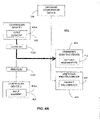
- FIG. 3 illustrates an example system 300 for controlling different combinations of operation-enacting devices (e.g., movable components) on a bicycle.
- the system 300 includes a plurality of controller devices 302.
- Each controller device 302 includes at least one respective input element 302a configured to receive input from a user.
- the controller devices 302 may include a first controller device coupled to a right side of a handlebar assembly and a second controller device coupled to a left side of the handlebar assembly, where respective shifter levers act as input elements 302a.
- input elements 302a may include any variety of shifter, pushbutton, clicker, switch, other toggled device, sensor (e.g., peddling sensor, etc.), or the like.
- a single controller device 302 may also include more than one input element 302a, (e.g., two shifter levers, a plurality of pushbuttons, etc.).
- the first controller device and the second controller device are a same type of controller device (e.g., same or identical shifters).
- the system 300 also includes a plurality of operation-enacting devices 304 (e.g., movable components).
- Each operation-enacting device 304 of the plurality of operation-enacting devices 304 is configured to enact at least one respective operation on the bicycle.
- the operation-enacting devices 304 may include a front derailleur, a rear derailleur, a height-adjustable seat post assembly, a front suspension system, and/or a rear suspension system as described above.
- Each operation-enacting device 304 may include at least one or be a movable component 311 configured to modify an operative state of the bicycle.
- an operation-enacting device 304 may act on more than one component of the bicycle in a single operation.
- a single operation may include more than one act on one or more components of the bicycle.
- the operation may include a physical action and a wireless action, where the wireless action sends wireless signals to cause further action by other cooperative device(s).
- the system 300 also includes a network coordinator device 306 (e.g., a pairing coordinator device).
- the network coordinator device 306 includes a first communication interface 306a configured to communicate wirelessly with the plurality of controller devices 302 and the plurality of operation-enacting devices 304. Using the first communication interface 306a, the network coordinator device 306 may establish a wireless network 308 that enables communications between the network coordinator device 306, the controller devices 302, and the operation-enacting devices 304.
- each controller device 302 of the plurality of controller devices 302 includes a communication interface 302c
- each operation-enacting device 304 of the plurality of operation-enacting devices 304 includes a communication interface 304a for communicating with other devices (e.g., receiving and transmitting data/signals) on the wireless network 308.
- the network coordinator device 306 may appear in FIG. 3 as a separate device, the features of a network coordinator device 306 in alternative embodiments may be provided by one or more of the other controller devices 302 and/or operation-enacting devices 304 such as a rear derailleur.
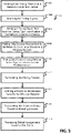
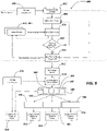
- FIG. 5 illustrates a method 500 for establishing a wireless network between a network coordinator device, controller devices and operation-enacting devices and establishing a set of default assignments that determine how the operating-enacting devices enact the operations in response to the signals received from the controller devices.
- the acts of the method presented below are intended to be illustrative. In some embodiment, the method may be accomplished with one or more additional acts not described, and/or without one or more of the acts discussed. Additionally, the order in which the acts of the method are illustrated in FIG. 5 and described below is not intended to be limiting.
- the method may be implemented in one or more processing device (e.g., digital processor, an analog processor, a digital circuit configured to process information, an analog-circuit configured to process information, a state machine, and/or other mechanisms for electronically processing information).
- the one or more processing devices include one or more devices executing some or all the acts of the method in response to instructions stored electronically on an electronic storage medium.
- the one or more processing devices are configured, through hardware, firmware, and/or software, for execution of one or more of the acts of the method.
- a network coordinator device (e.g., the network coordinator device 306) is configured to initiate a new pairing session to pair controller devices (the controller devices 302) and operation-enacting devices (e.g., the operation-enacting devices 304) to a wireless network (e.g., the wireless network 308).
- the user selects the network coordinator device from among the controller devices and the operation-enacting devices by operating a pairing input element (e.g., the pairing input element 306c) such as, for example, a pushbutton, switch, or the like that prompts the selected network coordinator device to initiate a new pairing session.
- a pairing input element e.g., the pairing input element 306c
- the network coordinator device scans for pairing signals from other devices.
- the user may selectively pair a controller device or an operation-enacting device to the wireless network by operating a corresponding pairing input element (e.g., a pairing input element 302d or 304b) such as a pushbutton, switch, or the like on the given device to be placed into pairing mode.
- a corresponding pairing input element e.g., a pairing input element 302d or 304b
- the selected device transmits a pairing signal to the network coordinator device in response to operation of the pairing input element of the selected device.
- the pairing signal allows the network coordinator device to recognize the given device and permit the given device to join the wireless network. If a proprietary network protocol is employed for the wireless network, only devices configured to communicate according to the proprietary network protocol may be recognized by the network coordinator device and paired.
- the pairing signal from a given device provides a respective device type identification, and the network coordinator device determines whether the given device is an assignable device based on the respective device type identification. If the network coordinator device determines the given device is an assignable device based on the respective device type identification, the network coordinator device assigns a next available assigned device type to the given device, and in act 510, the pairing signal allows the network coordinator device to permit the given device to join the wireless network.
- the assignment of assigned device types is discussed below further with reference to FIGS. 8-11 .
- the network coordinator device determines the given device is not an assignable device (e.g., determines the given device is a standard device)
- the network coordinator device only pairs devices having different respective device type identifications in act 510.
- the pairing signal may identify a given device to be a rear derailleur.
- the system e.g., the system 300
- the system will not include more than one rear derailleur. As such, an unknown device cannot imitate another device type that has already been selected for pairing.
- the user may manually end the pairing session (e.g., by operating the pairing input element 306c on the network coordinator device 306).
- the network coordinator device may automatically end the pairing session after a set time period has elapsed.
- a roster (e.g., a roster 310) is defined by the controller devices and the operation-enacting devices that have been paired to the wireless network at the end of the pairing session. To enhance the integrity of the system, no other devices may be paired to the wireless network 38 after the pairing session has ended. By fixing the roster, the system only includes the devices (e.g., devices 302 and/or 304) selected by the user. This blocks unauthorized devices from joining the wireless network and maliciously or accidentally interfering with the operation of the devices actually selected by the user.
- the network coordinator device when the pairing session ends, is configured to transmit, to the operation-enacting devices, the roster identifying the controller devices and the operation-enacting devices paired to the wireless network.
- the operation-enacting devices are configured to determine, based on the roster received from the network coordinator device, how to enact operations in response to signals (e.g., the signals 302b) received from the controller devices.
- a new pairing session may be initiated with the network coordinator device to reset the roster and to pair a different set of devices (e.g., devices 302 and/or 304). At the end of the new pairing session, this different set of devices defines a new roster.
- the new pairing session unpairs and resets all devices that may have been added to the wireless network in a previous pairing session.
- paired devices cannot be removed from the roster, and new devices cannot be added to the roster until a new pairing session is initiated.
- a device paired to the wireless network may be paired into another wireless network (e.g., on another bicycle system), but that device cannot rejoin the prior wireless network (e.g., the wireless network 308) because the prior wireless network is reset when paired to the other wireless network.
- the controller devices 302 are configured to transmit, to the operation-enacting devices 304, signals 302b indicating input received by the input elements 302a of the controller devices 302.
- a first controller device 302 e.g., the first controller device 120
- a second controller device 302 e.g., the second controller device 122
- may wirelessly transmit a first shift signal e.g., the first shift signal120b
- a second shift signal e.g., the second shift signal 120a
- a first input element e.g., the first shift lever 120a
- a second input element e.g., the second shift lever 122a
- the operation-enacting devices 304 are configured to process a default set of assignments 312 based on the roster 310 to determine how the operation-enacting devices 304 enact the operations responsive to the signals 302b.
- the default set of assignments 312 may be transmitted to each operation-enacting device 304 by the network coordinator device 306 and/or stored locally on each operation-enacting device 304.
- the roster 310 may include a first controller device with a first shift lever (e.g., a right shift lever), a second controller device with a second shift lever (e.g., left shift lever), a front derailleur, and a rear derailleur.
- the default set of assignments 312 controlling the operation of the operation-enacting devices 304 is determined according to the particular set of devices in the roster 310.
- the default set of assignments 312 may provide that with the example roster 310 above: (i) the rear derailleur shifts the chain to a sprocket inboard relative to the frame of the bicycle in response to signals from the second controller device (with no signals from the first controller device); (ii) the rear derailleur shifts the chain to a sprocket outboard relative to the frame in response to signals from the first controller device (with no signals from the second controller device); and (iii) the front derailleur shifts the chain to an alternate chainring in response to simultaneous signals from the first controller device and the second controller device.
- the default set of assignments 312 may be different. For example, if the roster 310 includes a height-adjustable seat post assembly and does not include a front derailleur, the seat post assembly lowers the seat in response to the simultaneous signals from the right and left controller devices.
- a paired device is considered to remain in the wireless network 308, and the roster 310 does not change even if the paired device becomes inactive or unavailable (e.g., loses power or is re-paired to another wireless network).
- Each operation enacted by the corresponding operation-enacting device 304 occurs only in response to the signals 302b from a single assigned controller device 302 or a single assigned combination of controller devices 302, as described below.
- an operation may involve shifting the chain to a sprocket inboard with the rear derailleur, and such operation only occurs in response to signals from the second controller device. This reduces the likelihood of an unwanted response by an operation-enacting device 304 to a signal from an unknown device.
- the combination of controller devices may be considered to be a single virtual controller device.
- an operation may involve the front derailleur shifting the chain to an alternate chainring, and such operation may only occur in response to signals from the single virtual controller device defined by the combination of the first controller device and the second controller device.
- a single virtual device may be provided by simultaneous signals from two or more inputs on a single device (e.g., simultaneous presses of pushbuttons on a single unified shifter device).
- FIG. 6 illustrates a method 600 for controlling operation-enacting devices (e.g., the operation-enacting devices 304).
- each operation-enacting device may receive, via the wireless network, the signals from the controller devices.
- each operation-enacting device may identify the one or more signals from an assigned controller device or from an assigned combination of controller devices.
- each operation-enacting device enacts the operation in response to the one or more signals from the assigned controller device or assigned combination of controller devices.
- the default set of assignments 312 may provide an effective approach for determining how the operation-enacting devices 304 should respond to the signals 302b from the controller devices 302, the user may prefer to use a modified set of assignments 312'.
- the modified set of assignments 312' may provide that with the example roster 310 above: (i) the rear derailleur shifts the chain to the inboard sprocket in response to signals from the first controller device that do not exceed a threshold amount of time (without signals from the second controller device); (ii) the rear derailleur shifts the chain to the outboard sprocket in response to signals from the first controller device that meet or exceed the threshold amount of time (without signals from the second controller device); and (iii) the front derailleur shifts the chain to an alternate chainring in response to signals from the second controller device.
- the network coordinator device 306 may include a second wired and/or wireless communication interface 306b configured to receive the modified set of assignments 312', where the modified set of assignments 312' causes at least one operation enacted by an operation-enacting device 304 to occur in response to the signals 302b from a different controller device 302.
- the second communication interface 306b may employ a different protocol than the first communication interface 306a (e.g., when the first communication interface 306a employs a proprietary protocol).
- FIG. 7 illustrates a method of modifying the default or current set of assignments.
- the network coordinator device e.g., the network coordinator device 306 receives a modified set of assignments (e.g., modified set of assignments 312' in FIG. 3 ).
- the network coordinator device transmits, via the wireless network (e.g., the wireless network 308), the modified set of assignments to the operation-enacting devices (e.g., operation-enacting devices 304).
- the operation-enacting devices replace the default or current set of assignments (e.g., the default set of assignments 312) with the modified set of assignments.
- the operation-enacting devices determine how the operation-enacting devices are to enact operations in response to the signals (e.g., the signals 302b) according to the modified set of assignments. If desired, the user may modify the set of assignments again in a similar manner.
- the second communication interface 306b is configured to wirelessly couple the network coordinator device 306 to an external computing device 314, such as a mobile device (e.g., a smart phone), a computing tablet, a laptop, a personal computer, or the like.
- the external computing device 314 may include an application 316, such as a mobile application or other computer software.
- the application 316 is configured to receive the modified set of assignments 312' from a user and to transmit the modified set of assignments 312' to the network coordinator device 306.
- FIGS. 4A-C illustrate example scenarios 400a-c that further demonstrate how a modified set of assignments may be implemented in the system 300.
- the controller devices 302 paired to the wireless network 308 include a first controller device 402 and a second controller device 403.
- the first controller device 402 includes a first input element 402a configured to receive a first input from the user. The first input from the user modifies a state of the first input element 402a.
- the second controller device 403 includes a second input element 403a configured to receive a second input from the user. The second input from the user modifies a state of the second input element 403a.
- the first input element 402a may be a right shift lever
- the second input element 403a may be a left shift lever.
- the user may engage either shift lever so that the state of the shift lever may be modified to any of the following: (i) an active state when engaged by the user for less than a threshold amount of time; (ii) an inactive state when not engaged by the user; or (iii) an update state when continuously engaged by the user for at least the threshold amount of time.
- the signals 302b from the controller devices 302 include a first signal 402b from the first controller device 402 and a second signal 403b from the second controller device 403.
- the first signal 402b indicates the modified state of the first input element 402a
- the second signal 403b indicates the modified state of the second input element 403a.
- the signals 302b from a particular controller device 302 may include a device type identification for the particular controller device 302, an input identifier for the input element 302a on the particular controller device 302 (in case there is more than one input element 302a), and information on the modified state for the input element 302a.
- the signals 302b may include more, less, and/or different data.
- the operation-enacting devices 304 include a first operation-enacting device 404 and a second operation-enacting device 405.
- the first operation-enacting device 404 may be a front suspension system
- the second operation-enacting device 405 may be a rear suspension system.
- the first operation-enacting device 404 is configured to: (i) identify the first signal 402b among the signals 302b received from the controller devices 302; (ii) identify the modified state of the first input element 402a; and (iii) enact a first operation on the bicycle in response to the modified state of the first input element 402a.
- the network coordinator device 306 is configured to (i) receive a second set of assignments 412', and (ii) transmit the second set of assignments 412' to the first operation-enacting device 404 via the wireless network 308.
- the first operation-enacting device 404 is configured to receive the second signal 403b from the second controller device 403 via the wireless network 308. Responsive to receiving the second set of assignments 412', the first operation-enacting device 404 is modified to: (i) identify the modified state of the second input element 403a, (ii) enact the first operation on the bicycle in response to the modified state of the second input element 403a, and (iii) remain idle in response to the first signal from the first controller device 402.
- the network coordinator device is configured to (i) receive a third set of assignments 412", and (ii) transmit the third set of assignments 412" to the operation-enacting devices 304 via the wireless network 308.
- the second operation-enacting device 405 is configured to receive the first signal 402b from the first controller device 402 via the wireless network 308.
- the second operation-enacting device 405 is configured to identify the modified state of the first input element 402a and to enact a second operation on the bicycle in response to the modified state of the first input element 402a, and (ii) the first operation-enacting device 404 is modified to remain idle in response to the first signal from the first controller device.
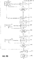
- FIG. 8 illustrates a method 800 for establishing a wireless network between a network coordinator device (e.g., a pairing coordinator device), controller devices (e.g., a number of assignable controller devices and a number of non-assignable, or standard, controller devices), and operation-enacting devices, and establishing a set of default assignments that determine how the operating-enacting devices enact the operations in response to the signals received from the controller devices.
- the acts of the method presented below are intended to be illustrative. In some embodiment, the method may be accomplished with one or more additional acts not described, and/or without one or more of the acts discussed. Additionally, the order in which the acts of the method are illustrated in FIG. 8 and described below is not intended to be limiting.
- the method may be implemented in one or more processing devices (e.g., digital processor, an analog processor, a digital circuit configured to process information, an analog-circuit configured to process information, a state machine, and/or other mechanisms for electronically processing information).
- the one or more processing devices include one or more devices executing some or all the acts of the method in response to instructions stored electronically on an electronic storage medium.
- the one or more processing devices configured, through hardware, firmware, and/or software, to be specifically configured for execution of one or more of the acts of the method.
- the network coordinator device (e.g., the network coordinator device 306) is configured to initiate a new pairing session to pair, for example, the controller devices (e.g., the controller devices 302) and the operation-enacting devices (e.g., the operation-enacting devices 304) to the wireless network (e.g., the wireless network 308).
- the user may select the network coordinator device from among, for example, the controller devices and operation-enacting devices by operating a pairing input element (e.g., the pairing input element 306c) such as a pushbutton, switch, or the like that prompts the selected network coordinator device to initiate a new pairing session.
- the network coordinator device scans for pairing signals from other devices. In other words, the network coordinator device searches for controller devices and operation-enacting devices that want to join the wireless network (e.g., joiners).
- the user may selectively pair a controller device or an operation-enacting device to the wireless network by operating a corresponding pairing input element such as a pushbutton, switch, or the like on the given device to be placed into pairing mode.
- a corresponding pairing input element such as a pushbutton, switch, or the like on the given device to be placed into pairing mode.
- the selected device While in pairing mode, in act 806, the selected device transmits a pairing signal to the network coordinator device in response to operation of the pairing input element of the selected device.
- the network coordinator device determines whether the selected device is an assignable device (e.g., an assignable controller devices).
- the network coordinator device may determine whether the selected device is, for example, an assignable controller based on the transmitted pairing signal.
- the transmitted pairing signal may include a device type code, and the network coordinator device may determine whether the selected device is an assignable controller based on the device type code within the transmitted pairing signal.
- a standard controller is programmed with static device type codes that do not change throughout a lifespan of the component.
- Each assignable controller may be programmed with an assignable device type (e.g., an assignable device type code) at manufacturing.
- the assignable device type code may be stored in a memory of the respective assignable controller).
- the assignable device type code may be 96 or 114, though additional, fewer, and/or different assignable device type codes may be provided.
- a first assignable device type code (e.g., 96) corresponds to a single button assignable controller
- a second assignable device type code (e.g., 114) corresponds to a two button assignable controller.
- one or more ranges of device type codes may correspond to one or more assignable controllers.
- device type codes of 96-113 may correspond to a single button assignable controller device
- device type codes of 114-127 may correspond to a two-button assignable controller device.
- each of the single button assignable controller devices may be programmed with a device type code (e.g., an assignable device type code) of 96
- each of the two-button assignable controller devices may be programmed with a device type code (e.g., an assignable device type code) of 114.
- these assignable device type codes programmed at manufacturing may be updated.
- the determination of whether the selected device is an assignable device may include comparing the device type code stored at the selected device to the one or more ranges of device type codes (e.g., within the range of device type codes of 96-113 for a single button assignable controller device and within the range of device type codes of 114-127 for a two-button assignable controller device).
- the method moves to act 810.
- the network coordinator device determines the selected device is not an assignable controller (e.g., is a standard controller)
- the pairing signal allows the network coordinator device to recognize the given device and permit the given device to join the wireless network. If a proprietary network protocol is employed for the wireless network (e.g., the wireless network 308), only devices configured to communicate according to the proprietary network protocol may be recognized by the network coordinator device and paired. The method then returns to act 804.
- the network coordinator device programs the selected device with a new assigned device type code.
- a memory of the selected device may store the new assigned device type code.
- the new assigned device type code is stored in the memory of the selected device, such that the device type code programmed at manufacturing, for example, is replaced.
- the network coordinator device programs selected devices the network coordinator device determines to be assignable devices new assigned device type codes in increasing numerical order based on the assignable device type (e.g., a single button assignable controller or a two button assignable controller) and an order in which the assignable devices are paired into the wireless network.
- the assignable device type e.g., a single button assignable controller or a two button assignable controller
- the network coordinator device 306 programs the selected device with the device type code of 97.
- the second single button assignable controller to be paired into the wireless network e.g., based on a device type of 96-113 is programmed with the device type code of 98
- the third single button assignable controller to be paired into the wireless network e.g., based on a device type of 96-113 is programmed with the device type code of 99. This pattern continues for each additional single button assignable controller that is to be paired into the wireless network.
- the network coordinator device programs the selected device with the device type code of 115.
- the second two button assignable controller to be paired into the wireless network e.g., based on a device type code of 114-127) is programmed with the device type code of 116, and the third assignable device to be paired into the wireless network (e.g., based on a device type code of 114-127) is programmed with the device type code of 117.
- This pattern continues for each additional two button assignable controller that is to be paired into the wireless network.
- Additional, fewer, and/or different device type codes may be used for single button assignable controllers and/or two button assignable controllers.
- the assignment of device types may be provided for assignable controllers with a greater number of buttons (e.g., three buttons).
- three button assignable controllers may be programed with a device type code of 128 at manufacturing and may be assigned a device type code of 129-141 depending on an order of pairing into the wireless network.
- the method returns to act 804 unless the pairing session is ended.
- the user may manually end the pairing session (e.g., by operating the pairing input element 306c on the network coordinator device 306).
- the network coordinator device may automatically end the pairing session after a set time period has elapsed.
- a roster (e.g., the roster 310) is defined by the controller devices and the operation-enacting devices that have been paired to the wireless network at the end of the pairing session. To enhance the integrity of the system, no other devices may be paired to the wireless network after the pairing session has ended. By fixing the roster, the system only includes the devices (e.g., the devices 302, 304) selected by the user. This blocks unauthorized devices from joining the wireless network and maliciously or accidentally interfering with the operation of the devices (e.g., the devices 302, 304) actually selected by the user.
- the network coordinator device transmits, to the operation-enacting devices, the roster identifying the controller devices and the operation-enacting devices paired to the wireless network.
- the operation-enacting devices are configured to determine, based on the roster received from the network coordinator device, how to enact operations in response to the signals (e.g., signals 302b) received from the controller devices.
- a new pairing session may be initiated with the network coordinator device to reset the roster and to pair a different set of devices (e.g., a different set of devices 302, 304).
- this different set of devices defines a new roster (e.g., a new roster 310).
- the new pairing session unpairs and resets all devices that may have been added to the wireless network in a previous pairing session.
- paired devices cannot be removed from the roster, and new devices cannot be added to the roster until a new pairing session is initiated.
- a device paired to the wireless network may be paired into another wireless network (e.g., on another bicycle system), but that device cannot rejoin the prior wireless network because the prior wireless network is reset when paired to the other wireless network.
- the operation-enacting devices are configured to process a default set of assignments (e.g., the default set of assignments 312) based on the roster (e.g., the roster 310) to determine how the operation-enacting devices enact the operations responsive to the signals (e.g., the signals 302b).
- the default set of assignments may be transmitted to each operation-enacting device by the network coordinator device and/or stored locally on each operation-enacting device 304.
- FIGS. 9A-9B illustrate an embodiment of a method 900 for establishing a wireless network between a network coordinator device, controller devices (e.g., a number of assignable controller devices and a number of non-assignable, or standard, controller devices), and operation-enacting devices.
- the controller devices include three two-button assignable controllers (e.g., flat bar shifters), the operation-enacting devices include a seat post assembly, a front derailleur, and a rear derailleur, and the rear derailleur is defined as the network coordinator device. Other devices may, however, be selected as the network coordinator device.
- the acts of the method presented below are intended to be illustrative. In some embodiments, the method may be accomplished with one or more additional acts not described, and/or without one or more of the acts discussed. Additionally, the order in which the acts of the method are illustrated in FIGS. 9A-9B and described below is not intended to be limiting.
- the method 900 may be implemented in one or more processing devices (e.g., digital processor, an analog processor, a digital circuit configured to process information, an analog-circuit configured to process information, a state machine, and/or other mechanisms for electronically processing information).
- the one or more processing devices include one or more devices executing some or all the acts of the method in response to instructions stored electronically on an electronic storage medium.
- the one or more processing devices configured through hardware, firmware, and/or software, for execution of one or more of the acts of the method.
- a network coordinator device e.g., the rear derailleur
- a network coordinator device is configured to initiate a new pairing session to pair, for example, the three two-button assignable controllers, the seat post assembly, and the front derailleur to a wireless network with the rear derailleur.
- the user may select the network coordinator device from among controller devices and operation-enacting devices of the bicycle by operating a pairing input element such as a pushbutton, switch, or the like that prompts the selected network coordinator device (e.g., the rear derailleur) to initiate a new pairing session.
- the rear derailleur While in the pairing mode, in act 904, the rear derailleur, for example, scans for pairing signals from other devices. In other words, the rear derailleur searches for controller devices and operation-enacting devices that want to join the wireless network (e.g., joiners).
- the rear derailleur searches for controller devices and operation-enacting devices that want to join the wireless network (e.g., joiners).
- the user may selectively pair a controller device or an operation-enacting device (e.g., a first selected device) to the wireless network by operating a corresponding pairing input element such as a pushbutton, switch, or the like on the given device to be placed into pairing mode.
- a controller device or an operation-enacting device e.g., a first selected device
- the first selected device transmits a pairing signal to the rear derailleur, for example, in response to operation of the pairing input element of the first selected device.
- the rear derailleur determines whether the first selected device is an assignable device (e.g., a first assignable controller).
- the rear derailleur may determine whether the first selected device is, for example, an assignable controller based on the transmitted pairing signal.
- the transmitted pairing signal may include a device type code, and the rear derailleur may determine whether the first selected device is an assignable controller based on the device type code within the transmitted pairing signal.
- the first selected device has a device type of 114, which indicates a two-button assignable controller, and the rear derailleur determines the first selected device is an assignable controller.
- the rear derailleur programs the first assignable controller with a new assigned device type code.
- the rear derailleur programs the first assignable controller with new assigned device type code 115, and the first assignable controller is allowed to pair into the wireless network.
- the new assigned device type code is stored in a memory of the first assignable controller (e.g., replacing an original or most recently stored device type code).
- the rear derailleur continues scanning for pairing signals from other devices. While still in pairing mode, in act 914, a second selected device transmits a pairing signal to the rear derailleur in response to operation of the pairing input element of the second device.
- the rear derailleur determines whether the second selected device is an assignable device (e.g., a second assignable controller).
- the rear derailleur may determine whether the second selected device is, for example, an assignable controller based on the transmitted pairing signal.
- the transmitted pairing signal may include a device type code, and the rear derailleur may determine whether the second selected device is an assignable controller based on the device type code within the transmitted pairing signal.
- the second selected device has a device type of 114, which indicates a two-button assignable controller, and the rear derailleur determines the second selected device is an assignable controller.
- the rear derailleur programs the second assignable controller with a new assigned device type code.
- the rear derailleur programs the second assignable controller with new assigned device type code 116, and the second assignable controller is allowed to pair into the wireless network.
- the rear derailleur continues scanning for pairing signals from other devices. While still in pairing mode, in act 922, a third selected device transmits a pairing signal to the rear derailleur in response to operation of the pairing input element of the third device.
- the rear derailleur determines whether the third selected device is an assignable device (e.g., a third assignable controller).
- the rear derailleur may determine whether the third selected device is, for example, an assignable controller based on the transmitted pairing signal.
- the transmitted pairing signal may include a device type code, and the rear derailleur may determine whether the third selected device is an assignable controller based on the device type code within the transmitted pairing signal.
- the third selected device has a device type of 114, which indicates a two-button assignable controller, and the rear derailleur determines the third selected device is an assignable controller.
- the rear derailleur programs the third assignable controller with a new assigned device type code.
- the rear derailleur programs the third assignable controller with new assigned device type code 117, and the third assignable controller is allowed to pair into the wireless network.
- the rear derailleur continues scanning for pairing signals from other devices. While still in pairing mode, in act 930, a fourth selected device transmits a pairing signal to the rear derailleur in response to operation of the pairing input element of the fourth device.
- the rear derailleur determines whether the fourth selected device is an assignable device.
- the rear derailleur may determine whether the fourth selected device is, for example, an assignable controller based on the transmitted pairing signal.
- the transmitted pairing signal may include a device type code, and the rear derailleur may determine whether the fourth selected device is an assignable controller based on the device type code within the transmitted pairing signal.
- the rear derailleur determines the fourth selected device is not an assignable device (e.g., determines the fourth selected device is a standard device).
- the rear derailleur only pairs standard devices having a different device type than the rear derailleur.
- the pairing signal may identify the fourth selected device to be a front derailleur, and the front derailleur is allowed to pair into the wireless network.
- the rear derailleur continues scanning for pairing signals from other devices. While still in pairing mode, in act 936, a fifth selected device transmits a pairing signal to the rear derailleur in response to operation of the pairing input element of the fifth device.
- the rear derailleur determines whether the fifth selected device is an assignable device.
- the rear derailleur may determine whether the fifth selected device is, for example, an assignable controller based on the transmitted pairing signal.
- the transmitted pairing signal may include a device type code, and the rear derailleur may determine whether the fifth selected device is an assignable controller based on the device type code within the transmitted pairing signal.
- the rear derailleur determines the fifth selected device is not an assignable device (e.g., determines the fifth selected device is a standard device).
- the rear derailleur only pairs standard devices having a different device type than the rear derailleur and the front derailleur.
- the pairing signal may identify the fifth selected device to be a seat post assembly, and the seat post assembly is allowed to pair into the wireless network.
- the rear derailleur continues scanning for pairing signals from other devices.
- the user may manually end the pairing session (e.g., by operating the pairing input element on the rear derailleur).
- the rear derailleur may automatically end the pairing session after a set time period has elapsed.
- the network coordinator device e.g., the rear derailleur
- the default reactions are mapped to, for example, the assignable controllers.
- a first button of the first assignable controller has a default reaction of an outboard shift
- a second button of the first assignable controller has a default reaction of an inboard shift.
- the first assignable controller may have a default reaction of an outboard shift
- the second assignable controller may have a default reaction of an inboard shift.
- FIG. 10 illustrates an embodiment of a method for mapping default reactions to assignable controllers.
- the method shown in FIG. 10 may be a continuation of the method of FIG. 9 or another method for establishing a wireless network.
- the acts of the method presented below are intended to be illustrative. In some embodiment, the method may be accomplished with one or more additional acts not described, and/or without one or more of the acts discussed. Additionally, the order in which the acts of the method are illustrated in FIG. 10 and described below is not intended to be limiting.
- the method may be implemented in one or more processing devices (e.g., digital processor, an analog processor, a digital circuit configured to process information, an analog-circuit configured to process information, a state machine, and/or other mechanisms for electronically processing information).
- the one or more processing devices include one or more devices executing some or all the acts of the method in response to instructions stored electronically on an electronic storage medium.
- the one or more processing devices are configured, through hardware, firmware, and/or software, for execution of one or more of the acts of the method.
- a roster is defined by the controller devices and the operation-enacting devices that have been paired to the wireless network at the end of the pairing session (e.g., the first assignable controller, the second assignable controller, the third assignable controller, the rear derailleur, the front derailleur, and the seat post assembly).
- the system only includes the devices selected by the user. This blocks unauthorized devices from joining the wireless network and maliciously or accidentally interfering with the operation of the devices actually selected by the user.
- the rear derailleur when the pairing session ends, is configured to transmit, to the operation-enacting devices of the wireless network (e.g., the front derailleur (FD) and the seat post (SP) assembly), the roster identifying the controller devices (e.g., the first assignable controller device, the second assignable controller device, and the third assignable controller device) and the operation-enacting devices (e.g., the rear derailleur (RD), the front derailleur (FD), and the seat post (SP) assembly) paired to the wireless network.
- the RD, the FD, and the SP assembly as illustrated in FIG.
- 10 are configured to determine, based on the roster transmitted by the rear derailleur, how to enact operations in response to signals received from the first assignable controller device FB1, the second assignable controller device FB2, and the third assignable controller device FB3.
- the first assignable controller device FB1 which was the first assignable controller device paired into the wireless network, is assigned a first default action or control and a second default action or control.
- a first button (e.g., first input element) of the first assignable controller device FB1 is assigned an action of inboard shift of the RD
- a second button (e.g., second input element) of the first assignable controller FB1 is assigned an action of outboard shift of the RD.
- the second assignable controller device FB2 which was the second assignable controller device paired into the wireless network, is assigned a third default action or control.
- a first button and a second button of the second assignable controller device FB2 are both assigned an action of actuation of a dropper of the SP assembly.
- the third assignable controller device FB3 does not have a default action
- the FD does not have a default associated controller device.
- Different mapping may be provided with different pairing orders. If assignable controller devices are re-paired into a new system, device types are again overwritten to be programmed with a new assigned device type by a pairing coordinator device (e.g., the network coordinator device).
- a pairing coordinator device e.g., the network coordinator device.
- the second assignable controller device FB2 may control the RD instead of the first assignable controller device FB1.
- the first assignable controller device FB1 may control the SP assembly instead of the second assignable controller device FB2.
- controller devices both standard controller devices and assignable controller devices
- the designations may be reconfigured via, for example, a mobile device application (e.g., the application 316) in communication with the network coordinator.
- a mobile device application e.g., the application 316
- Assignable controller devices are configured for multiple of a same controller device to be mounted on the bicycle 100, with placement of the assignable controller devices 302 on the bicycle 100 being at the discretion of the user. While the user may use a mobile device application (e.g., the application 316), for example, to reconfigure designations, representations of the same assignable controller devices 302, for example, may have a same name and same artwork (e.g., icon) within a graphical user interface (GUI) displayed within the application 316 at a display of a mobile device (e.g., the external computing device 314).
- GUI graphical user interface
- the representations may thus be difficult to distinguish from each other within the application 316. For example, if the user builds a bicycle with two standard controllers and two assignable controllers, when the user opens the application 316, representations of four devices are displayed within the application 316. While each representation of the two standard controllers displays unique art (e.g., a unique icon) and a unique name, the user may not be able to determine which representation within the application 316 (e.g., which icon) corresponds to which assignable controller device 302.
- FIG. 12 illustrates a method 1200 for indicating, within a mobile application or other software (e.g., a mobile device application), which input element (e.g., button) of which controller device has been pressed.
- the acts of the method 1200 presented below are intended to be illustrative. In some embodiments, the method 1200 may be accomplished with one or more additional acts not described, and/or without one or more of the acts discussed. Additionally, the order in which the acts of the method 1200 are illustrated in FIG. 12 and described below is not intended to be limiting.
- the method 1200 may be implemented in one or more processing devices (e.g., digital processor, an analog processor, a digital circuit configured to process information, an analog-circuit configured to process information, a state machine, and/or other mechanisms for electronically processing information).
- the one or more processing devices include one or more devices executing some or all the acts of the method 1200 in response to instructions stored electronically on an electronic storage medium.
- the one or more processing devices are configured, through hardware, firmware, and/or software, for execution of one or more of the acts of the method.
- Controller 0 is a first assignable controller device
- Controller 1 is a second assignable controller device on a bicycle (e.g., the bicycle 100).
- the first assignable controller device and the second assignable controller device are same controller devices (e.g., identical controller devices).
- Bridge Device corresponds to a coordinator device (e.g., the network coordinator device 306) or another computing device (e.g., a controller device) on the bicycle.
- AXS App corresponds to, for example, an application (e.g., the application 316) running on a mobile device (e.g., the external computing device 314).
- the coordinator device is in communication with the first assignable controller device, the second assignable controller device, and the application running on the mobile device.
- the coordinator device is in communication with the first assignable controller device and the second assignable controller device via a first wireless network (e.g., established via pairing session as described above), and is in communication with the mobile device via a second wireless network.
- data may be communicated via the first wireless network and the second wireless network using different protocols or standards.
- data may be communicated via the first wireless network and the second wireless network using a same protocol or standard.
- the first wireless network and the second wireless network may be parts of an overall wireless network, via which at least the coordinator device, the first assignable controller device, the second assignable controller device, and the mobile device may communicate.
- the first assignable controller device in response to user input (e.g., a button press) at an input element (e.g., a button) of the first assignable controller device, the first assignable controller device generates and transmits a message or signal (e.g., a button message) to the coordinator device.
- the first assignable controller device also transmits the button message to other devices of the bicycle (e.g., paired within the first wireless network of the bicycle).
- the first assignable controller device may transmit the button message to all receivers of the first wireless network of the bicycle (e.g., all controller devices and operation-enacting devices paired to the coordinator device).
- the button message includes data identifying a device type and data identifying the input element, the activation of which initiated the generation of the button message.
- the data identifying the device type may be, for example, a device type code, as discussed above, and the data identifying the input element may be a bitmask (e.g., a button mask) with one or more bits associated with, for example, the first assignable controller (e.g., associated with one or more input elements or buttons of the first assignable controller).
- the bitmask may include bits associated with one or more input elements of the first assignable controller, respectively, and a bit of the bitmask may be set when a corresponding input element is activated.
- the coordinator device stores the data identifying the device type and the data identifying the input element for the first assignable controller device within a memory of the coordinator device.
- the coordinator device may store the data identifying the device type and the data identifying the input element within cache of the coordinator device.
- the coordinator device In act 1206, the coordinator device generates a notification based on the button message received by the coordinator device.
- the coordinator device transmits the notification to the application running on the mobile device via the second wireless network.
- the notification identifies that a new controller device has been heard by the coordinator device.
- the mobile device in response to the notification transmitted to the mobile device by the coordinator device, the mobile device (e.g., via the application running on the mobile device) generates a request and transmits the request to the coordinator device via the second wireless network.
- the request is for information about the newly heard controller device (e.g., data related to the received button message).
- the coordinator device retrieves the data identifying the device type and the data identifying the input element (e.g., the button mask) for the first assignable controller device stored (e.g., cached) at the coordinator device.
- the coordinator device transmits, for example, the cached data to the mobile device via, for example, the second wireless network.
- the cached data may be the only cached data related to device type and input element stored at the coordinator device. For example, when the coordinator device stores the data identifying the device type and the data identifying the input element within cache of the coordinator device, the coordinator device may overwrite device type data and input element identification data previously stored in the cache of the coordinator device.
- the cached data retrieved in act 1210 may be the most-recently cached data at the coordinator device.
- the application running on the mobile device highlights the representation of the first assignable controller within the mobile device application based on the received cached data.
- the mobile device or another device in communication with the mobile device stores data associated with the representation of the first assignable controller displayed within the GUI of the application running on the mobile device.
- the mobile device stores a device type and one or more button masks for each device displayed within the application, and the mobile device compares the received cached data to the data stored at the mobile device to identify which representation (e.g., which button representation within which device representation displayed within the GUI of the application running on the mobile device) to highlight.
- the application running on the mobile device may highlight the identified representation within the application in any number of ways including. For example, the mobile device may highlight the identified representation within the application by increasing a brightness of (e.g., lighting up) the identified representation and/or changing a color of the identified representation. In one embodiment, the application running on the mobile device highlights the identified representation for a predetermined amount of time (e.g., one second, two seconds, or five seconds). In another embodiment, the application running on the mobile device highlights the identified representation until another representation within the application is to be highlighted (e.g., when another input element is activated).
- a predetermined amount of time e.g., one second, two seconds, or five seconds.
- acts 1202-1212 being repeated for the second assignable controller device.
- Acts 1202-1212 of the method 1200 may be repeated any number of times for any number of controller devices (e.g., assignable controller device) paired to the first wireless network.
- acts 1202-1212 of the method 1200 are repeated each time an input element of a controller device paired with the coordinator device via the first wireless network is activated by user input.
- acts 1202-1212 of the method 1200 are repeated each time an input element of an assignable controller device paired with the coordinator device via the first wireless network is activated by user input.
- FIG. 13 is a visual representation of user experience for a method of indicating, within an application running on a mobile device, for example, which input element (e.g., button) of which controller device has been pressed.
- FIG. 13 illustrates a system 1300 of a bicycle (e.g., the bicycle 100) that includes a rear derailleur 1302 that acts as a coordinator device (e.g., a bridge device), a first controller device 1304, a second controller device 1306, a third controller device 1308, and a front derailleur 1310.
- the system 1300 may include more, fewer, and/or different components.
- the system 1300 may include more or fewer controller devices.
- the rear derailleur 1302, the first controller device 1304, the second controller device 1306, the third controller device 1308, and the front derailleur 1310 are in communication with each other via a wireless network (e.g., a first wireless network 1312).
- a wireless network e.g., a first wireless network 1312
- the first controller device 1304, the second controller device 1306, the third controller device 1308, and the front derailleur 1310 are paired to the rear derailleur 1302, as discussed above, to form the first wireless network 1312.
- the rear derailleur 1302 acting as, for example, the coordinator device is in communication with a mobile device 1314 (e.g., a mobile phone) via the wireless network or another wireless network (e.g., a second wireless network 1316).
- the first wireless network 1312 and the second wireless network 1316 may be parts of an overall wireless network that operates with a same standard or protocol, or the first wireless network 1312 and the second wireless network 1316 may be different wireless networks that operate with different standards or protocols, respectively.
- the mobile device 1314 is configured to run an application 1318 that includes a GUI 1320 displayed by the mobile device 1314.
- the application 1318 may facilitate (e.g., via the GUI 1320), for example, the configuration of components (e.g., the rear derailleur 1302 and the front derailleur 1310) of the system 1300 of the bicycle and/or the modification of assignments (e.g., the default set of assignments).
- the application 1318 may provide additional and/or different functionality.
- the GUI 1320 displayed within the application 1318 includes representations of at least assignable controller devices (e.g., the first controller device 1304 and the second controller device 1306) paired with the coordinator device (e.g., the rear derailleur 1302) within the first wireless network 1312.
- the GUI 1320 displayed within the application 1318 includes representations of all components of the system 1300 (e.g., all components paired to the rear derailleur 1302 within the first wireless network 1312).
- Representations for the unique components of the system 1300 e.g., the rear derailleur 1302, the third controller device 1308, and the front derailleur 1310) may have unique representations (not shown) displayed within the GUI 1320 of the application 1318, respectively.
- Such unique components of the system 1300 may be identifiable by the corresponding representations within the GUI 1320.
- Assignable controller devices e.g., the first controller device 1304 and the second controller device 1306) that are a same type of controller device (e.g., identical controller devices; single button controller devices, two-button controller devices, or three-button controller devices) may not be identifiable by corresponding representations within the GUI 1320, respectively.
- a representation 1322 of the first assignable controller device 1304 and a representation 1324 of the second controller device 1306 displayed within the GUI 1320 of the application 1318 running on the mobile device 1314 may be the same.
- the first controller device 1304 includes three input elements 1326a-c (e.g., buttons), the second controller device 1306 includes three input elements 1328a-c (e.g., buttons), and the third controller device 1308 includes three input elements 1330a-c (e.g., buttons).
- the representation 1322 of the first assignable controller device 1304 may correspondingly include three representations 1332a-c of input elements, and the representation 1324 of the second controller device 1306 may correspondingly include three representations 1334a-c of input elements.
- the first controller device 1304 and the second controller device 1306, and the corresponding controller device representations 1322, 1324, may include more or fewer input elements.
- the first controller device 1304 transmits data identifying which button on which controller was pressed (e.g., a device type code and a button mask; button identification data) to the coordinator device (e.g., a bridge device such as the rear derailleur 1302).
- the coordinator device 1302 ultimately transmits the button identification data to the mobile device 1314 running the application 1318.
- the mobile device 1314 identifies which input element representation (e.g., representation 1332a, 1332b, 1332c, 1334a, 1334b, or 1334c) of which controller device representation (e.g., representation 1322 or 1324) within the GUI 1320 of the application 1318 running on the mobile device 1314 corresponds to the received button identification data, and mobile device 1314 highlights the identified representation (e.g., representation 1332b) within the GUI 1320 of the application 1318. For example, the mobile device matches the received button identification data with data corresponding to a representation (e.g., the representation 1332b) within the GUI 1320 of the application 1318. Through this process, the user is able to easily identify identical components (e.g., identical shifters) without having to guess which controller device corresponds to which representation within the GUI 1320 of the application 1318.
- identical components e.g., identical shifters
- the network coordinator device 306 may include one or more processors 306d configured to execute program instructions stored on computer-readable media 306e, which when executed cause the one or more processors 306d to: (i) establish, via the first communication interface 306c, a pairing session that allows the controller devices 302 and the operation-enacting devices 304 to be paired to a wireless network 308, and (ii) transmit to the operation-enacting devices 304, via the first communication interface 306c, a roster 310 identifying the controller devices 302 and the operation-enacting devices 304 paired to the wireless network 308.
- an operation-enacting device 304 may include one or more processors 304c configured to execute program instructions stored on computer-readable media 304d, the program instructions causing the one or more processors 306d to process the default set of assignments 312 based on the roster 310, where the default set of assignments 312 indicates which of the controller devices 302 is selected to cause the operation-enacting device 304 to respond by modifying the operative state of the bicycle.
- the one or more processors 304c of the operation-enacting devices 304 receive, via the communication interface 304a, a modified set of assignments 312' from the network coordinator device 306, where the modified set of assignments 312' causes the operation-enacting device 304 to modify the operative state of the bicycle in response to the signals 302b from a different one of the controller devices; the program instructions cause the one or more processors 304c to replace the default or current set of assignments 312 with the modified set of assignments 312'.
- the one or more processors 302e, 304c, 306d employed by the embodiments may include a general processor, digital signal processor, an application specific integrated circuit (ASIC), field programmable gate array (FPGA), analog circuit, digital circuit, combinations thereof, or other now known or later developed processor.
- the processor may be a single device or combinations of devices, such as through shared or parallel processing.
- Such memory may be a volatile memory or a non-volatile memory.
- the memory may include one or more of a read only memory (ROM), random access memory (RAM), a flash memory, an electronic erasable program read only memory (EEPROM), or other type of memory.
- the memory may be removable from the corresponding device, such as a secure digital (SD) memory card.
- Computer memory includes any one or more of a computer-readable medium and other equivalents and successor media, in which data or instructions may be stored.
- a computer-readable medium includes any medium that is capable of storing, encoding, or carrying a set of instructions for execution by a processor or that cause a computer system to perform any one or more of the methods or operations disclosed herein.
- embodiments employ power supplies, which may be stored internal to the operating device, or stored external to the operating device.
- the power supply may include a combination of multiple batteries or other power providing devices. Specially fitted or configured battery types, or standard battery types such as CR 2012, CR 2016, and/or CR 2032 may be used.
- the devices in a system are all individually powered (e.g., by a dedicated battery).
- the embodiments employ communication interfaces.
- Such communication interfaces are configured to send data such as control signals and/or commands to bicycle components.
- the communication interface provides for wireless communications in any now known or later developed format.
- standards for Internet and other packet switched network transmission e.g., TCP/IP, UDP/IP, HTML, HTTP, HTTPS
- Such standards are periodically superseded by faster or more efficient equivalents having essentially the same functions. Accordingly, replacement standards and protocols having the same or similar functions as those disclosed herein are considered equivalents thereof.
- the illustration or other representation of devices include (even if not expressly labeled) any combination of processor(s), memory device(s) (e.g., computer-readable media storing program instructions for execution by processor(s)), communication interface(s), and power supply necessary to achieve the disclosed features.
Landscapes
- Engineering & Computer Science (AREA)
- Mechanical Engineering (AREA)
- Chemical & Material Sciences (AREA)
- Combustion & Propulsion (AREA)
- Transportation (AREA)
- Computer Networks & Wireless Communication (AREA)
- Computing Systems (AREA)
- General Health & Medical Sciences (AREA)
- Medical Informatics (AREA)
- Health & Medical Sciences (AREA)
- Signal Processing (AREA)
- Physics & Mathematics (AREA)
- General Physics & Mathematics (AREA)
- Selective Calling Equipment (AREA)
Applications Claiming Priority (2)
| Application Number | Priority Date | Filing Date | Title |
|---|---|---|---|
| US202163191996P | 2021-05-22 | 2021-05-22 | |
| US17/746,872 US20220371681A1 (en) | 2021-05-22 | 2022-05-17 | Assignable pairing order |
Publications (2)
| Publication Number | Publication Date |
|---|---|
| EP4091927A2 true EP4091927A2 (fr) | 2022-11-23 |
| EP4091927A3 EP4091927A3 (fr) | 2022-12-21 |
Family
ID=81750371
Family Applications (1)
| Application Number | Title | Priority Date | Filing Date |
|---|---|---|---|
| EP22174618.3A Pending EP4091927A3 (fr) | 2021-05-22 | 2022-05-20 | Ordre d'appariement attribuable |
Country Status (5)
| Country | Link |
|---|---|
| US (1) | US20220371681A1 (fr) |
| EP (1) | EP4091927A3 (fr) |
| CN (1) | CN115384667A (fr) |
| DE (1) | DE102022112784A1 (fr) |
| TW (1) | TW202246123A (fr) |
Families Citing this family (1)
| Publication number | Priority date | Publication date | Assignee | Title |
|---|---|---|---|---|
| DE102022204093A1 (de) * | 2022-04-27 | 2023-11-02 | Shimano Inc. | Umwerfer für ein menschlich angetriebenes fahrzeug |
Family Cites Families (5)
| Publication number | Priority date | Publication date | Assignee | Title |
|---|---|---|---|---|
| ITPD20120349A1 (it) * | 2012-11-15 | 2014-05-16 | Claudio Tiso | Metodo di controllo elettronico con telefono mobile smartphone per il cambio del rapporto di trasmissione della bicicletta |
| US10933949B2 (en) * | 2014-11-27 | 2021-03-02 | Shimano Inc. | Bicycle operating apparatus and bicycle operating system |
| DE102016010801A1 (de) * | 2015-09-22 | 2017-03-23 | Sram Deutschland Gmbh | Ansteuereinrichtung zum drahtlosen Ansteuern wenigstens einer Komponente eines Fahrrads |
| TWI773552B (zh) * | 2019-01-29 | 2022-08-01 | 美商速聯有限責任公司 | 用於自行車之系統 |
| US11066122B2 (en) * | 2019-05-30 | 2021-07-20 | Shimano Inc. | Control device and control system including control device |
-
2022
- 2022-05-17 US US17/746,872 patent/US20220371681A1/en active Pending
- 2022-05-19 TW TW111118739A patent/TW202246123A/zh unknown
- 2022-05-20 DE DE102022112784.2A patent/DE102022112784A1/de active Pending
- 2022-05-20 EP EP22174618.3A patent/EP4091927A3/fr active Pending
- 2022-05-23 CN CN202210561000.3A patent/CN115384667A/zh active Pending
Also Published As
| Publication number | Publication date |
|---|---|
| CN115384667A (zh) | 2022-11-25 |
| EP4091927A3 (fr) | 2022-12-21 |
| US20220371681A1 (en) | 2022-11-24 |
| DE102022112784A1 (de) | 2022-11-24 |
| TW202246123A (zh) | 2022-12-01 |
Similar Documents
| Publication | Publication Date | Title |
|---|---|---|
| US20210284284A1 (en) | System for a bicycle | |
| CN111483546B (zh) | 自行车的系统、网络协调器设备和操作执行设备 | |
| EP2003051B1 (fr) | Procédé pour contrôler électroniquement un changement de vitesses de bicyclette et système électronique de bicyclette | |
| EP4091927A2 (fr) | Ordre d'appariement attribuable | |
| EP2492181B1 (fr) | Dispositif de réglage de contrôle de suspension de bicyclette et appareil de contrôle de suspension de bicyclette | |
| CN103661707A (zh) | 自行车换档通知设备 | |
| TW201238823A (en) | Bicycle suspension control apparatus | |
| EP4091926A2 (fr) | Dispositif de coordination | |
| EP4163198B1 (fr) | Commande de faible puissance pour un dispositif de commande de bicyclette | |
| TWI834292B (zh) | 用於自行車之電子自行車組件及系統 | |
| CN115967923A (zh) | 多协议兼容自行车部件配对 | |
| US11945533B2 (en) | Bicycle component control | |
| NL2033111B1 (en) | Bicycle transmission control system | |
| WO2024012834A1 (fr) | Système de commande de transmission de vélo |
Legal Events
| Date | Code | Title | Description |
|---|---|---|---|
| PUAI | Public reference made under article 153(3) epc to a published international application that has entered the european phase |
Free format text: ORIGINAL CODE: 0009012 |
|
| STAA | Information on the status of an ep patent application or granted ep patent |
Free format text: STATUS: REQUEST FOR EXAMINATION WAS MADE |
|
| PUAL | Search report despatched |
Free format text: ORIGINAL CODE: 0009013 |
|
| 17P | Request for examination filed |
Effective date: 20220520 |
|
| AK | Designated contracting states |
Kind code of ref document: A2 Designated state(s): AL AT BE BG CH CY CZ DE DK EE ES FI FR GB GR HR HU IE IS IT LI LT LU LV MC MK MT NL NO PL PT RO RS SE SI SK SM TR |
|
| AK | Designated contracting states |
Kind code of ref document: A3 Designated state(s): AL AT BE BG CH CY CZ DE DK EE ES FI FR GB GR HR HU IE IS IT LI LT LU LV MC MK MT NL NO PL PT RO RS SE SI SK SM TR |
|
| RIC1 | Information provided on ipc code assigned before grant |
Ipc: H04L 61/00 20220101ALI20221111BHEP Ipc: H04L 61/5092 20220101ALI20221111BHEP Ipc: B62J 1/08 20060101ALI20221111BHEP Ipc: B62M 9/122 20100101ALI20221111BHEP Ipc: B62M 25/08 20060101ALI20221111BHEP Ipc: B62L 3/02 20060101ALI20221111BHEP Ipc: B62K 23/02 20060101ALI20221111BHEP Ipc: B62J 45/00 20200101AFI20221111BHEP Ipc: B62M 9/132 20100101ALI20221111BHEP |