EP4090839B1 - Entschärfen von partikelemissionen im motorabgas - Google Patents
Entschärfen von partikelemissionen im motorabgas Download PDFInfo
- Publication number
- EP4090839B1 EP4090839B1 EP21705316.4A EP21705316A EP4090839B1 EP 4090839 B1 EP4090839 B1 EP 4090839B1 EP 21705316 A EP21705316 A EP 21705316A EP 4090839 B1 EP4090839 B1 EP 4090839B1
- Authority
- EP
- European Patent Office
- Prior art keywords
- vehicle
- particulate matter
- hydrogen
- cell
- implementations
- Prior art date
- Legal status (The legal status is an assumption and is not a legal conclusion. Google has not performed a legal analysis and makes no representation as to the accuracy of the status listed.)
- Active
Links
Images



Classifications
-
- F—MECHANICAL ENGINEERING; LIGHTING; HEATING; WEAPONS; BLASTING
- F01—MACHINES OR ENGINES IN GENERAL; ENGINE PLANTS IN GENERAL; STEAM ENGINES
- F01N—GAS-FLOW SILENCERS OR EXHAUST APPARATUS FOR MACHINES OR ENGINES IN GENERAL; GAS-FLOW SILENCERS OR EXHAUST APPARATUS FOR INTERNAL-COMBUSTION ENGINES
- F01N3/00—Exhaust or silencing apparatus having means for purifying, rendering innocuous, or otherwise treating exhaust
- F01N3/02—Exhaust or silencing apparatus having means for purifying, rendering innocuous, or otherwise treating exhaust for cooling, or for removing solid constituents of, exhaust
- F01N3/021—Exhaust or silencing apparatus having means for purifying, rendering innocuous, or otherwise treating exhaust for cooling, or for removing solid constituents of, exhaust by means of filters
- F01N3/023—Exhaust or silencing apparatus having means for purifying, rendering innocuous, or otherwise treating exhaust for cooling, or for removing solid constituents of, exhaust by means of filters using means for regenerating the filters, e.g. by burning trapped particles
- F01N3/029—Exhaust or silencing apparatus having means for purifying, rendering innocuous, or otherwise treating exhaust for cooling, or for removing solid constituents of, exhaust by means of filters using means for regenerating the filters, e.g. by burning trapped particles by adding non-fuel substances to exhaust
- F01N3/0293—Exhaust or silencing apparatus having means for purifying, rendering innocuous, or otherwise treating exhaust for cooling, or for removing solid constituents of, exhaust by means of filters using means for regenerating the filters, e.g. by burning trapped particles by adding non-fuel substances to exhaust injecting substances in exhaust stream
-
- F—MECHANICAL ENGINEERING; LIGHTING; HEATING; WEAPONS; BLASTING
- F01—MACHINES OR ENGINES IN GENERAL; ENGINE PLANTS IN GENERAL; STEAM ENGINES
- F01N—GAS-FLOW SILENCERS OR EXHAUST APPARATUS FOR MACHINES OR ENGINES IN GENERAL; GAS-FLOW SILENCERS OR EXHAUST APPARATUS FOR INTERNAL-COMBUSTION ENGINES
- F01N3/00—Exhaust or silencing apparatus having means for purifying, rendering innocuous, or otherwise treating exhaust
- F01N3/02—Exhaust or silencing apparatus having means for purifying, rendering innocuous, or otherwise treating exhaust for cooling, or for removing solid constituents of, exhaust
- F01N3/021—Exhaust or silencing apparatus having means for purifying, rendering innocuous, or otherwise treating exhaust for cooling, or for removing solid constituents of, exhaust by means of filters
- F01N3/023—Exhaust or silencing apparatus having means for purifying, rendering innocuous, or otherwise treating exhaust for cooling, or for removing solid constituents of, exhaust by means of filters using means for regenerating the filters, e.g. by burning trapped particles
-
- B—PERFORMING OPERATIONS; TRANSPORTING
- B01—PHYSICAL OR CHEMICAL PROCESSES OR APPARATUS IN GENERAL
- B01D—SEPARATION
- B01D46/00—Filters or filtering processes specially modified for separating dispersed particles from gases or vapours
- B01D46/66—Regeneration of the filtering material or filter elements inside the filter
- B01D46/80—Chemical processes for the removal of the retained particles, e.g. by burning
-
- C—CHEMISTRY; METALLURGY
- C25—ELECTROLYTIC OR ELECTROPHORETIC PROCESSES; APPARATUS THEREFOR
- C25B—ELECTROLYTIC OR ELECTROPHORETIC PROCESSES FOR THE PRODUCTION OF COMPOUNDS OR NON-METALS; APPARATUS THEREFOR
- C25B1/00—Electrolytic production of inorganic compounds or non-metals
- C25B1/01—Products
- C25B1/02—Hydrogen or oxygen
- C25B1/04—Hydrogen or oxygen by electrolysis of water
-
- C—CHEMISTRY; METALLURGY
- C25—ELECTROLYTIC OR ELECTROPHORETIC PROCESSES; APPARATUS THEREFOR
- C25B—ELECTROLYTIC OR ELECTROPHORETIC PROCESSES FOR THE PRODUCTION OF COMPOUNDS OR NON-METALS; APPARATUS THEREFOR
- C25B9/00—Cells or assemblies of cells; Constructional parts of cells; Assemblies of constructional parts, e.g. electrode-diaphragm assemblies; Process-related cell features
- C25B9/17—Cells comprising dimensionally-stable non-movable electrodes; Assemblies of constructional parts thereof
-
- F—MECHANICAL ENGINEERING; LIGHTING; HEATING; WEAPONS; BLASTING
- F01—MACHINES OR ENGINES IN GENERAL; ENGINE PLANTS IN GENERAL; STEAM ENGINES
- F01N—GAS-FLOW SILENCERS OR EXHAUST APPARATUS FOR MACHINES OR ENGINES IN GENERAL; GAS-FLOW SILENCERS OR EXHAUST APPARATUS FOR INTERNAL-COMBUSTION ENGINES
- F01N3/00—Exhaust or silencing apparatus having means for purifying, rendering innocuous, or otherwise treating exhaust
- F01N3/02—Exhaust or silencing apparatus having means for purifying, rendering innocuous, or otherwise treating exhaust for cooling, or for removing solid constituents of, exhaust
- F01N3/021—Exhaust or silencing apparatus having means for purifying, rendering innocuous, or otherwise treating exhaust for cooling, or for removing solid constituents of, exhaust by means of filters
- F01N3/023—Exhaust or silencing apparatus having means for purifying, rendering innocuous, or otherwise treating exhaust for cooling, or for removing solid constituents of, exhaust by means of filters using means for regenerating the filters, e.g. by burning trapped particles
- F01N3/029—Exhaust or silencing apparatus having means for purifying, rendering innocuous, or otherwise treating exhaust for cooling, or for removing solid constituents of, exhaust by means of filters using means for regenerating the filters, e.g. by burning trapped particles by adding non-fuel substances to exhaust
-
- F—MECHANICAL ENGINEERING; LIGHTING; HEATING; WEAPONS; BLASTING
- F01—MACHINES OR ENGINES IN GENERAL; ENGINE PLANTS IN GENERAL; STEAM ENGINES
- F01N—GAS-FLOW SILENCERS OR EXHAUST APPARATUS FOR MACHINES OR ENGINES IN GENERAL; GAS-FLOW SILENCERS OR EXHAUST APPARATUS FOR INTERNAL-COMBUSTION ENGINES
- F01N3/00—Exhaust or silencing apparatus having means for purifying, rendering innocuous, or otherwise treating exhaust
- F01N3/02—Exhaust or silencing apparatus having means for purifying, rendering innocuous, or otherwise treating exhaust for cooling, or for removing solid constituents of, exhaust
- F01N3/021—Exhaust or silencing apparatus having means for purifying, rendering innocuous, or otherwise treating exhaust for cooling, or for removing solid constituents of, exhaust by means of filters
- F01N3/033—Exhaust or silencing apparatus having means for purifying, rendering innocuous, or otherwise treating exhaust for cooling, or for removing solid constituents of, exhaust by means of filters in combination with other devices
-
- F—MECHANICAL ENGINEERING; LIGHTING; HEATING; WEAPONS; BLASTING
- F02—COMBUSTION ENGINES; HOT-GAS OR COMBUSTION-PRODUCT ENGINE PLANTS
- F02B—INTERNAL-COMBUSTION PISTON ENGINES; COMBUSTION ENGINES IN GENERAL
- F02B43/00—Engines characterised by operating on gaseous fuels; Plants including such engines
- F02B43/10—Engines or plants characterised by use of other specific gases, e.g. acetylene, oxyhydrogen
- F02B43/12—Methods of operating
-
- H—ELECTRICITY
- H02—GENERATION; CONVERSION OR DISTRIBUTION OF ELECTRIC POWER
- H02S—GENERATION OF ELECTRIC POWER BY CONVERSION OF INFRARED RADIATION, VISIBLE LIGHT OR ULTRAVIOLET LIGHT, e.g. USING PHOTOVOLTAIC [PV] MODULES
- H02S10/00—PV power plants; Combinations of PV energy systems with other systems for the generation of electric power
- H02S10/40—Mobile PV generator systems
-
- B—PERFORMING OPERATIONS; TRANSPORTING
- B01—PHYSICAL OR CHEMICAL PROCESSES OR APPARATUS IN GENERAL
- B01D—SEPARATION
- B01D2279/00—Filters adapted for separating dispersed particles from gases or vapours specially modified for specific uses
- B01D2279/30—Filters adapted for separating dispersed particles from gases or vapours specially modified for specific uses for treatment of exhaust gases from IC Engines
-
- F—MECHANICAL ENGINEERING; LIGHTING; HEATING; WEAPONS; BLASTING
- F01—MACHINES OR ENGINES IN GENERAL; ENGINE PLANTS IN GENERAL; STEAM ENGINES
- F01N—GAS-FLOW SILENCERS OR EXHAUST APPARATUS FOR MACHINES OR ENGINES IN GENERAL; GAS-FLOW SILENCERS OR EXHAUST APPARATUS FOR INTERNAL-COMBUSTION ENGINES
- F01N2240/00—Combination or association of two or more different exhaust treating devices, or of at least one such device with an auxiliary device, not covered by indexing codes F01N2230/00 or F01N2250/00, one of the devices being
- F01N2240/04—Combination or association of two or more different exhaust treating devices, or of at least one such device with an auxiliary device, not covered by indexing codes F01N2230/00 or F01N2250/00, one of the devices being an electric, e.g. electrostatic, device other than a heater
-
- F—MECHANICAL ENGINEERING; LIGHTING; HEATING; WEAPONS; BLASTING
- F01—MACHINES OR ENGINES IN GENERAL; ENGINE PLANTS IN GENERAL; STEAM ENGINES
- F01N—GAS-FLOW SILENCERS OR EXHAUST APPARATUS FOR MACHINES OR ENGINES IN GENERAL; GAS-FLOW SILENCERS OR EXHAUST APPARATUS FOR INTERNAL-COMBUSTION ENGINES
- F01N2240/00—Combination or association of two or more different exhaust treating devices, or of at least one such device with an auxiliary device, not covered by indexing codes F01N2230/00 or F01N2250/00, one of the devices being
- F01N2240/16—Combination or association of two or more different exhaust treating devices, or of at least one such device with an auxiliary device, not covered by indexing codes F01N2230/00 or F01N2250/00, one of the devices being an electric heater, i.e. a resistance heater
-
- F—MECHANICAL ENGINEERING; LIGHTING; HEATING; WEAPONS; BLASTING
- F01—MACHINES OR ENGINES IN GENERAL; ENGINE PLANTS IN GENERAL; STEAM ENGINES
- F01N—GAS-FLOW SILENCERS OR EXHAUST APPARATUS FOR MACHINES OR ENGINES IN GENERAL; GAS-FLOW SILENCERS OR EXHAUST APPARATUS FOR INTERNAL-COMBUSTION ENGINES
- F01N2240/00—Combination or association of two or more different exhaust treating devices, or of at least one such device with an auxiliary device, not covered by indexing codes F01N2230/00 or F01N2250/00, one of the devices being
- F01N2240/34—Combination or association of two or more different exhaust treating devices, or of at least one such device with an auxiliary device, not covered by indexing codes F01N2230/00 or F01N2250/00, one of the devices being an electrolyser
-
- F—MECHANICAL ENGINEERING; LIGHTING; HEATING; WEAPONS; BLASTING
- F01—MACHINES OR ENGINES IN GENERAL; ENGINE PLANTS IN GENERAL; STEAM ENGINES
- F01N—GAS-FLOW SILENCERS OR EXHAUST APPARATUS FOR MACHINES OR ENGINES IN GENERAL; GAS-FLOW SILENCERS OR EXHAUST APPARATUS FOR INTERNAL-COMBUSTION ENGINES
- F01N2610/00—Adding substances to exhaust gases
- F01N2610/04—Adding substances to exhaust gases the substance being hydrogen
-
- F—MECHANICAL ENGINEERING; LIGHTING; HEATING; WEAPONS; BLASTING
- F01—MACHINES OR ENGINES IN GENERAL; ENGINE PLANTS IN GENERAL; STEAM ENGINES
- F01N—GAS-FLOW SILENCERS OR EXHAUST APPARATUS FOR MACHINES OR ENGINES IN GENERAL; GAS-FLOW SILENCERS OR EXHAUST APPARATUS FOR INTERNAL-COMBUSTION ENGINES
- F01N3/00—Exhaust or silencing apparatus having means for purifying, rendering innocuous, or otherwise treating exhaust
- F01N3/02—Exhaust or silencing apparatus having means for purifying, rendering innocuous, or otherwise treating exhaust for cooling, or for removing solid constituents of, exhaust
- F01N3/021—Exhaust or silencing apparatus having means for purifying, rendering innocuous, or otherwise treating exhaust for cooling, or for removing solid constituents of, exhaust by means of filters
- F01N3/023—Exhaust or silencing apparatus having means for purifying, rendering innocuous, or otherwise treating exhaust for cooling, or for removing solid constituents of, exhaust by means of filters using means for regenerating the filters, e.g. by burning trapped particles
- F01N3/025—Exhaust or silencing apparatus having means for purifying, rendering innocuous, or otherwise treating exhaust for cooling, or for removing solid constituents of, exhaust by means of filters using means for regenerating the filters, e.g. by burning trapped particles using fuel burner or by adding fuel to exhaust
- F01N3/0253—Exhaust or silencing apparatus having means for purifying, rendering innocuous, or otherwise treating exhaust for cooling, or for removing solid constituents of, exhaust by means of filters using means for regenerating the filters, e.g. by burning trapped particles using fuel burner or by adding fuel to exhaust adding fuel to exhaust gases
- F01N3/0256—Exhaust or silencing apparatus having means for purifying, rendering innocuous, or otherwise treating exhaust for cooling, or for removing solid constituents of, exhaust by means of filters using means for regenerating the filters, e.g. by burning trapped particles using fuel burner or by adding fuel to exhaust adding fuel to exhaust gases the fuel being ignited by electrical means
-
- F—MECHANICAL ENGINEERING; LIGHTING; HEATING; WEAPONS; BLASTING
- F01—MACHINES OR ENGINES IN GENERAL; ENGINE PLANTS IN GENERAL; STEAM ENGINES
- F01N—GAS-FLOW SILENCERS OR EXHAUST APPARATUS FOR MACHINES OR ENGINES IN GENERAL; GAS-FLOW SILENCERS OR EXHAUST APPARATUS FOR INTERNAL-COMBUSTION ENGINES
- F01N3/00—Exhaust or silencing apparatus having means for purifying, rendering innocuous, or otherwise treating exhaust
- F01N3/02—Exhaust or silencing apparatus having means for purifying, rendering innocuous, or otherwise treating exhaust for cooling, or for removing solid constituents of, exhaust
- F01N3/021—Exhaust or silencing apparatus having means for purifying, rendering innocuous, or otherwise treating exhaust for cooling, or for removing solid constituents of, exhaust by means of filters
- F01N3/023—Exhaust or silencing apparatus having means for purifying, rendering innocuous, or otherwise treating exhaust for cooling, or for removing solid constituents of, exhaust by means of filters using means for regenerating the filters, e.g. by burning trapped particles
- F01N3/027—Exhaust or silencing apparatus having means for purifying, rendering innocuous, or otherwise treating exhaust for cooling, or for removing solid constituents of, exhaust by means of filters using means for regenerating the filters, e.g. by burning trapped particles using electric or magnetic heating means
-
- F—MECHANICAL ENGINEERING; LIGHTING; HEATING; WEAPONS; BLASTING
- F01—MACHINES OR ENGINES IN GENERAL; ENGINE PLANTS IN GENERAL; STEAM ENGINES
- F01N—GAS-FLOW SILENCERS OR EXHAUST APPARATUS FOR MACHINES OR ENGINES IN GENERAL; GAS-FLOW SILENCERS OR EXHAUST APPARATUS FOR INTERNAL-COMBUSTION ENGINES
- F01N5/00—Exhaust or silencing apparatus combined or associated with devices profiting by exhaust energy
- F01N5/02—Exhaust or silencing apparatus combined or associated with devices profiting by exhaust energy the devices using heat
- F01N5/025—Exhaust or silencing apparatus combined or associated with devices profiting by exhaust energy the devices using heat the device being thermoelectric generators
-
- F—MECHANICAL ENGINEERING; LIGHTING; HEATING; WEAPONS; BLASTING
- F02—COMBUSTION ENGINES; HOT-GAS OR COMBUSTION-PRODUCT ENGINE PLANTS
- F02B—INTERNAL-COMBUSTION PISTON ENGINES; COMBUSTION ENGINES IN GENERAL
- F02B43/00—Engines characterised by operating on gaseous fuels; Plants including such engines
- F02B43/10—Engines or plants characterised by use of other specific gases, e.g. acetylene, oxyhydrogen
- F02B2043/106—Hydrogen obtained by electrolysis
-
- Y—GENERAL TAGGING OF NEW TECHNOLOGICAL DEVELOPMENTS; GENERAL TAGGING OF CROSS-SECTIONAL TECHNOLOGIES SPANNING OVER SEVERAL SECTIONS OF THE IPC; TECHNICAL SUBJECTS COVERED BY FORMER USPC CROSS-REFERENCE ART COLLECTIONS [XRACs] AND DIGESTS
- Y02—TECHNOLOGIES OR APPLICATIONS FOR MITIGATION OR ADAPTATION AGAINST CLIMATE CHANGE
- Y02E—REDUCTION OF GREENHOUSE GAS [GHG] EMISSIONS, RELATED TO ENERGY GENERATION, TRANSMISSION OR DISTRIBUTION
- Y02E10/00—Energy generation through renewable energy sources
- Y02E10/50—Photovoltaic [PV] energy
-
- Y—GENERAL TAGGING OF NEW TECHNOLOGICAL DEVELOPMENTS; GENERAL TAGGING OF CROSS-SECTIONAL TECHNOLOGIES SPANNING OVER SEVERAL SECTIONS OF THE IPC; TECHNICAL SUBJECTS COVERED BY FORMER USPC CROSS-REFERENCE ART COLLECTIONS [XRACs] AND DIGESTS
- Y02—TECHNOLOGIES OR APPLICATIONS FOR MITIGATION OR ADAPTATION AGAINST CLIMATE CHANGE
- Y02E—REDUCTION OF GREENHOUSE GAS [GHG] EMISSIONS, RELATED TO ENERGY GENERATION, TRANSMISSION OR DISTRIBUTION
- Y02E60/00—Enabling technologies; Technologies with a potential or indirect contribution to GHG emissions mitigation
- Y02E60/30—Hydrogen technology
- Y02E60/36—Hydrogen production from non-carbon containing sources, e.g. by water electrolysis
-
- Y—GENERAL TAGGING OF NEW TECHNOLOGICAL DEVELOPMENTS; GENERAL TAGGING OF CROSS-SECTIONAL TECHNOLOGIES SPANNING OVER SEVERAL SECTIONS OF THE IPC; TECHNICAL SUBJECTS COVERED BY FORMER USPC CROSS-REFERENCE ART COLLECTIONS [XRACs] AND DIGESTS
- Y02—TECHNOLOGIES OR APPLICATIONS FOR MITIGATION OR ADAPTATION AGAINST CLIMATE CHANGE
- Y02P—CLIMATE CHANGE MITIGATION TECHNOLOGIES IN THE PRODUCTION OR PROCESSING OF GOODS
- Y02P20/00—Technologies relating to chemical industry
- Y02P20/10—Process efficiency
- Y02P20/133—Renewable energy sources, e.g. sunlight
-
- Y—GENERAL TAGGING OF NEW TECHNOLOGICAL DEVELOPMENTS; GENERAL TAGGING OF CROSS-SECTIONAL TECHNOLOGIES SPANNING OVER SEVERAL SECTIONS OF THE IPC; TECHNICAL SUBJECTS COVERED BY FORMER USPC CROSS-REFERENCE ART COLLECTIONS [XRACs] AND DIGESTS
- Y02—TECHNOLOGIES OR APPLICATIONS FOR MITIGATION OR ADAPTATION AGAINST CLIMATE CHANGE
- Y02T—CLIMATE CHANGE MITIGATION TECHNOLOGIES RELATED TO TRANSPORTATION
- Y02T10/00—Road transport of goods or passengers
- Y02T10/10—Internal combustion engine [ICE] based vehicles
- Y02T10/12—Improving ICE efficiencies
Definitions
- This disclosure relates to treatment of vehicle exhaust gas.
- Particulate matter can be present in exhaust gas produced by vehicles during operation. Particulate matter, if released into the atmosphere, can contribute to air pollution. After treatments of the engine exhaust gas can be used to reduce the amount of particulate matter emitted by such vehicles. Improving efficiency and effectiveness of such after treatments can be a favorable environmental and commercial endeavor.
- EP 3 124 780 A1 describes a vehicle drive system that includes an internal combustion engine for driving a vehicle, wherein the internal combustion engine comprises a combustion chamber with injectors for injecting diesel into the combustion chamber, a supply line for delivering a gas mixture to the combustion chamber, an electrolysis chamber for producing hydrogen gas and oxygen gas, and a vacuum pump for sucking the hydrogen gas and the oxygen gas from the electrolysis chamber.
- the vehicle drive system furthermore comprises a gasification tank with volatile organic compounds received therein, in particular methanol or ethanol, as well as a supply line for supplying a gas mixture to the combustion chamber, wherein the gas mixture comprises gasified organic compounds from the gasification tank and at least a part of the hydrogen gas and the oxygen gas.
- US 8 459 213 B2 describes the recovery of energy that is converted to electrical energy and powers the on-board electrolyzer to produce more hydrogen and oxygen while the system is in operation and stationary.
- Stationary, passive forms of energy e.g., solar, wind, hydro, etc. are available to power the electrolyzer.
- DE 10 2012 205534 A1 describes after-treating exhaust in an automobile.
- Energy may be received from a solar energy source electrically connected to an after-treatment system. At least some of the energy from the solar energy source may be provided to the after-treatment system to purify exhaust from an engine.
- a control module may provide at least some of the energy from the solar energy source to a heater, for example, to initiate heating the after-treatment system prior to starting the engine
- WO 2018/185660 A1 describes a vehicle on-board system configured to generate hydrogen and to introduce the generated hydrogen into an exhaust gas stream of an internal combustion engine, the system including a water-splitting article configured to split water into hydrogen and oxygen and a hydrogen injection article configured to introduce the hydrogen into the exhaust gas stream
- This disclosure describes technologies relating to treatment of vehicle exhaust gas, and more specifically, mitigating soot and particulate matter (PM) emissions in engine exhausts.
- PM particulate matter
- an onboard vehicle exhaust gas treating system is implemented according to claim 10.
- the first and second general aspects taken alone or in combination, can include one or more of the following features.
- producing the first oxygen stream and the first hydrogen stream includes recovering water from an engine exhaust gas generated by the vehicle during vehicle operation and electrolyzing the recovered water.
- the first hydrogen stream is provided to an engine of the vehicle.
- a waste heat recovery system mounted onboard the vehicle and coupled to an engine exhaust gas recovers energy from the engine exhaust gas. In some implementations, the waste heat recovery system converts the recovered energy to electricity. In some implementations, the electrochemical cell is powered by using the electricity converted by the waste heat recovery system.
- an electric heater is powered by using at least one of the electricity converted by the photovoltaic cell or the electricity converted by the waste heat recovery system.
- the electric heater generates heat in response to the powering.
- the particulate matter filter is heated by using the heat generated by the electric heater.
- a solar collector mounted onboard the vehicle and coupled to a photocatalytic cell mounted onboard the vehicle collects sunlight.
- an optical fiber transports the collected sunlight to the photocatalytic cell.
- the photocatalytic cell produces a second oxygen stream and a second hydrogen stream in response to receiving the collected sunlight.
- the second oxygen stream is provided to the particulate matter filter.
- producing the second oxygen stream and the second hydrogen stream includes recovering water from the engine exhaust gas and photo-catalytically splitting the recovered water.
- the second hydrogen stream is provided to an engine of the vehicle.
- the second hydrogen stream is combusted to produce heat.
- the heat produced from combusting the second hydrogen stream is provided to the particulate matter filter.
- the system includes a waste heat recovery system.
- the waste heat recovery system includes at least one of a thermoelectric generator or a turbine.
- the waste heat recovery system is configured to mount to the vehicle.
- the waste heat recovery system is configured to couple to an engine exhaust outlet of the vehicle.
- the waste heat recovery system is configured to recover energy from the engine exhaust gas.
- the waste heat recovery system is configured to convert the recovered energy to electricity.
- the waste heat recovery system is configured to deliver the electricity to the electrochemical cell.
- the system includes an electric heater.
- the electric heater is configured to mount to the vehicle.
- the electric heater is configured to couple to at least one of the photovoltaic cell or the waste heat recovery system.
- the electric heater is configured to generate heat in response to receiving electricity from at least one of the photovoltaic cell or the waste heat recovery system.
- the system includes a solar collector, an optical fiber, and a photocatalytic cell.
- the solar collector is configured to mount to the vehicle and collect sunlight.
- the optical fiber is configured to transport the collected sunlight from the solar collector to the photocatalytic cell.
- the photocatalytic cell is configured to mount to the vehicle and produce a second oxygen stream and a second hydrogen stream in response to receiving the collected sunlight.
- the system includes a hydrogen flow pathway configured to flow the second hydrogen stream from the photocatalytic cell to an engine of the vehicle.
- the system includes a hydrogen flow pathway configured to flow the second hydrogen stream from the photocatalytic cell to an ignition device positioned near the particulate matter filter.
- the technology described here generally relates to mitigating soot and particulate matter (PM) emissions in engine exhausts, including for example, in diesel engine exhausts and in gasoline engine exhausts.
- PM emissions can be mitigated by oxidization of the PM into less harmful products, such as carbon dioxide and water vapor.
- oxygen and heat can be provided to aid the oxidization of the PM.
- heat can be provided to aid the oxidization of the PM, and in cases where additional oxygen would improve the oxidation of the PM, oxygen can also be provided.
- the oxygen can be provided, for example, by onboard generation of oxygen through electrochemical water splitting, by onboard generation of oxygen through photocatalytic water splitting, by supply of air, or a combination of these.
- heat is provided by onboard waste heat recovery, by solar flux collected from the roof of the vehicle or elsewhere on the vehicle, by electricity generated onboard by a photovoltaic, combustion of hydrogen generated from onboard water splitting, or a combination of these.
- one or more components are powered by onboard waste heat recovery, by onboard conversion of solar flux collected from the roof of the vehicle or elsewhere on the vehicle, by electricity generated onboard by a photovoltaic, by electricity generated onboard by photocatalytic water splitting, or a combination of these.
- each of the components of the described technology can be mounted onboard a vehicle.
- all components of the described technology are configured such that the entire system is onboard the vehicle and can therefore travel with the vehicle and be used while the vehicle is in operation.
- the described technology can be implemented in vehicles with engines that operate or compression ignition or that use an igniter, like spark plug, heat plug, or other type of ignitor.
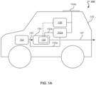
- FIG. 1A shows a vehicle exhaust gas treating system 100 onboard a vehicle 150.
- the vehicle 150 includes an engine 152.
- the vehicle 150 includes an after treatment system 154.
- the after treatment system 154 is configured to treat an exhaust gas 153 produced by the engine 152 during operation of the vehicle 150.
- the after treatment system 154 can include a particulate matter filter 156.
- the treated exhaust gas 157 is emitted from the vehicle 150.
- the vehicle exhaust gas treating system 100 supplements the after treatment system 154.
- the vehicle exhaust gas treating system 100 is configured to mount to the vehicle 150.
- the vehicle exhaust gas treating system 100 includes an electrochemical cell 102a, a photovoltaic cell 104a, and an electric heater 106.
- the electrochemical cell 102a is coupled to the photovoltaic cell 104a.
- the electric heater 106 is coupled to the photovoltaic cell 104a.
- the electrochemical cell 102a is configured to hold water.
- the electrochemical cell 102a includes electrodes. Each of the electrodes can include, for example, platinum, stainless steel, or iridium.
- the electrodes of the electrochemical cell 102a are connected to and powered by the photovoltaic cell 104a.
- the electrochemical cell 102a is configured to produce oxygen and hydrogen by electrolysis of water in response to receiving power.
- the electrochemical cell 102a is powered entirely or partially by the photovoltaic cell 104a.
- water is recovered, condensed, or both from the engine exhaust gas 153.
- water is supplied by an auxiliary water tank that can be filled, for example, by the end-user.
- the system 100 includes an oxygen flow pathway 103a configured to flow oxygen from the electrochemical cell 102a to the particulate matter filter 156.
- the oxygen provided to the particulate matter filter 156 can cause particulate matter (disposed on the particulate matter filter 156) to oxidize. Oxidation of the particulate matter can convert the particulate matter into gaseous components, such as carbon dioxide and water vapor. Conversion of the particulate matter into gaseous components, in turn, regenerates the particulate matter filter 156.
- the system 100 includes a hydrogen flow pathway 105a configured to flow hydrogen from the electrochemical cell 102a to the engine 152, where the hydrogen can mix with fuel and be combusted.
- the engine 152 is a spark ignition engine
- adding hydrogen to the engine 152 can improve overall efficiency, can improve engine operation, and can reduce the amount of emissions produced by the engine 152.
- the engine 152 is a compression ignition engine
- adding hydrogen to the engine 152 can reduce the amount of nitrous oxide and soot in emissions, promote auto-ignition of non-diesel fuels (for example, gasoline), or both.
- the system 100 includes a hydrogen flow pathway configured to flow hydrogen from the electrochemical cell 102a to an ignition device positioned near the particulate matter filter 156.
- the ignition device can combust the hydrogen, and the combustion of hydrogen in the vicinity of the particulate matter filter 156 can cause particulate matter disposed on the particulate matter filter 156 to burn.
- the combustion of hydrogen in the vicinity of the particulate matter filter 156 can also cause the temperature of the particulate matter filter 156 to increase.
- the combustion of hydrogen itself does not result in the production of carbon dioxide.
- the photovoltaic cell 104a is configured to convert solar energy into electricity.
- the photovoltaic cell 201 is a device whose electric characteristics, such as current, voltage, or resistance, vary when exposed to light (for example, light from the sun).
- the photovoltaic cell 201 includes a semiconducting material (for example, silicon) that can absorb photons (for example, from sunlight).
- the photovoltaic cell 201 converts solar energy into direct current (DC) electricity.
- the photovoltaic cell 201 includes an inverter that converts the power to alternating current (AC).
- the electric heater 106 is an electrical device that converts electric power into heat.
- the electric heater 106 includes a heating element that is an electric resister. As electric current passes through the resister, electrical energy is converted into heat energy.
- the resister can, for example, be made of nichrome.
- the electric heater 106 is powered entirely or partially by the photovoltaic cell 104a.
- the heat generated by the electric heater 106 is used to increase the temperature of the particulate matter filter 156.
- the electric heater 106 is configured to heat the particulate matter filter 156 to a temperature of about 500 degrees Celsius (°C) or greater.
- the electric heater 106 can be configured to heat the particulate matter filter 156 to a temperature of about 550°C, about 600°C, or about 650°C. Increasing the temperature of the particulate matter filter 156 to a temperature of about 500°C or greater can improve oxidation of the particulate matter (for example, disposed on the particulate matter filter 156 or flowing with the exhaust gas).
- Increasing the temperature of the particulate matter filter 156 to a temperature of about 500°C or greater can accelerate oxidation of the particulate matter (for example, disposed on the particulate matter filter 156 or flowing with the exhaust gas) to a rate that is quick enough to reduce the amount of particulate matter that is emitted from the vehicle 150 to an acceptable level (for example, less than 3 milligrams per mile (mg/mi) or less than 1 mg/mi).
- an acceptable level for example, less than 3 milligrams per mile (mg/mi) or less than 1 mg/mi).
- the hydrogen produced by the electrochemical cell 102a (or a portion of the hydrogen produced by the electrochemical cell 102a) is combusted to produce heat, which can be used to increase the temperature of the particulate matter filter 156.
- heat produced from combusting hydrogen is provided to the particulate matter filter 156 alternative to or in combination with the heat generated by the electric heater 106.
- FIG. 1B shows the system 100 including a waste heat recovery system 104b.
- the waste heat recovery system 104b can recover energy from the exhaust gas 153.
- the waste heat recovery system 104b is coupled to the engine exhaust gas 153. Any type of waste heat recovery system suitable for recovering energy from the exhaust gas 153 can be used in the system 100.
- the system 100 includes thermoelectric conversion or turbo-compounding.
- the waste heat recovery system 104b can convert the recovered energy to electricity.
- the recovered energy or electricity is used to power other units or processes in the system 100.
- the waste heat recovery system 104b includes at least one of a thermoelectric generator or a turbine.
- the waste heat recovery system 104b includes a Rankine cycle that includes a turbine.
- the electricity generated by the waste heat recovery system 104b is used to power other units or processes in the system 100 alternative to or in combination with the electricity generated by the photovoltaic cell 104a.
- the electrochemical cell 102a is powered (a) partially by the photovoltaic cell 104a, (b) partially by the waste heat recovery system 104b, (c) partially by the photovoltaic cell 104a and partially by the waste heat recovery system 104b, (d) entirely by the photovoltaic cell 104a, or (e) entirely by the waste heat recovery system 104b.
- the electric heater 106 is powered (a) partially by the photovoltaic cell 104a, (b) partially by the waste heat recovery system 104b, (c) partially by the photovoltaic cell 104a and partially by the waste heat recovery system 104b, (d) entirely by the photovoltaic cell 104a, or (e) entirely by the waste heat recovery system 104b.
- FIG. 1C shows the system 100 including a photocatalytic cell 102b and a solar collector 108.
- the photocatalytic cell 102b is configured to produce oxygen and hydrogen by photo-catalysis of water.
- Some non-limiting examples of photocatalysts include: cadmium zinc sulfide (Cd 1- x Zn x S, where 0.2 ⁇ x ⁇ 0.35); sodium tantalum oxide doped with lanthanum (NaTaO 3 :La); potassium tantalum borate (K 3 Ta 3 B 2 O 12 ); photocatalysts that include gallium, zinc, nitrogen, and oxygen; photocatalysts based on cobalt, bismuth vanadate, or tungsten diselenide (WSe 2 ); titanium dioxide (TiO 2 ); and photocatalysts based on III-V semiconductors (such as indium gallium phosphide, InGaP).
- Cd 1- x Zn x S
- the photocatalytic cell 102b includes a photocatalyst and a container made of glass or plastic.
- the photocatalytic cell 102b is configured to hold water.
- water is recovered, condensed, or both from the engine exhaust gas 153.
- water is supplied by an auxiliary water tank that can be filled, for example, by the end-user.
- the solar collector 108 is a device that collects sunlight, concentrates sunlight, or both.
- the solar collector 108 is connected to the photocatalytic cell 102b.
- the solar collector 108 is connected to the photocatalytic cell 102b by an optical fiber.
- the optical fiber transports the collected sunlight from the solar collector 108 to the photocatalytic cell 102b.
- the photocatalytic cell 102b splits water to produce oxygen and hydrogen.
- the system 100 includes an oxygen flow pathway 103b configured to flow oxygen from the photocatalytic cell 102b to the particulate matter filter 156.
- the system 100 includes a hydrogen flow pathway 105b configured to flow hydrogen from the photocatalytic cell 102b to the engine 152, where the hydrogen can mix with fuel and be combusted.
- the system 100 includes a hydrogen flow pathway configured to flow hydrogen from the photocatalytic cell 102b to an ignition device positioned near the particulate matter filter 156.
- the ignition device can combust the hydrogen, and the combustion of hydrogen in the vicinity of the particulate matter filter 156 can cause particulate matter disposed on the particulate matter filter 156 to burn.
- the combustion of hydrogen in the vicinity of the particulate matter filter 156 can also cause the temperature of the particulate matter filter 156 to increase.
- the combustion of hydrogen itself does not result in the production of carbon dioxide.
- the hydrogen produced by the photocatalytic cell 102b (or a portion of the hydrogen produced by the photocatalytic cell 102b) is combusted to produce heat, which can be used to increase the temperature of the particulate matter filter 156.
- heat produced from combusting hydrogen is provided to the particulate matter filter 156 alternative to or in combination with the heat generated by the electric heater 106.
- the system 100 includes a lamp that can be powered to produce photons for use by the photocatalytic cell 102b in photo-catalytically splitting water to produce oxygen and hydrogen.
- the photons produced by the lamp can supplement the sunlight collected by the solar collector 108. Electricity from the photovoltaic cell 104a, from the waste heat recovery system 104b, or from both can be used to power the lamp.
- the lamp is powered (a) partially by the photovoltaic cell 104a, (b) partially by the waste heat recovery system 104b, (c) partially by the photovoltaic cell 104a and partially by the waste heat recovery system 104b, (d) entirely by the photovoltaic cell 104a, or (e) entirely by the waste heat recovery system 104b.
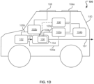
- FIG. 1D illustrates an implementation of the system 100 that includes all of the aforementioned components: the electrochemical cell 102a, photocatalytic cell 102b, photovoltaic cell 104a, waste heat recovery system 104b, electric heater 106, solar collector 108, oxygen flow pathways 103a and 103b, and hydrogen flow pathways 105a and 105b.
- the system 100 includes a hydrogen flow pathway configured to flow hydrogen from the at least one of the electrochemical cell 102a or the photocatalytic cell 102b to an ignition device positioned near the particulate matter filter 156.
- the ignition device can combust the hydrogen, and the combustion of hydrogen in the vicinity of the particulate matter filter 156 can cause particulate matter disposed on the particulate matter filter 156 to burn.
- the combustion of hydrogen in the vicinity of the particulate matter filter 156 can also cause the temperature of the particulate matter filter 156 to increase.
- the combustion of hydrogen itself does not result in the production of carbon dioxide.
- FIG. 2 is a flow chart of an example method 200 for treating exhaust gas (for example, the exhaust gas 153 from engine 152) onboard a vehicle (for example, the vehicle 150).
- the method 200 can be implemented, for example, by the system 100.
- solar energy is converted into electricity.
- solar energy is converted into electricity at step 202 by a photovoltaic cell (for example, the photovoltaic cell 104a) onboard the vehicle 150.
- the photovoltaic cell 104a is coupled to an electrochemical cell (for example, the electrochemical cell 102a).
- energy is recovered from the engine exhaust gas 153.
- the energy from the engine exhaust gas 153 is recovered by a waste heat recovery system mounted onboard the vehicle 150 and coupled to an engine exhaust outlet (for example, the waste heat recovery system 104b).
- the waste heat recovery system 104b converts the recovered energy to electricity.
- the electrochemical cell 102a is powered. In some implementations, the electrochemical cell 102a is powered at step 204 by using the electricity converted by the photovoltaic cell 104a at step 202. In some implementations, the electrochemical cell 102a is powered at step 204 by using the electricity converted by the waste heat recovery system 104b. In some implementations, the electrochemical cell 102a is powered at step 204 by using the electricity converted by the photovoltaic cell 104a at step 202 and the electricity converted by the waste heat recovery system 104b.
- oxygen is produced.
- oxygen is produced at step 206 by electrolysis of water by the electrochemical cell 102a in response to being powered at step 204. Electrolysis of water also produces hydrogen. Therefore, in some implementations, oxygen and hydrogen are produced by the electrochemical cell 102a at step 206.
- water is recovered, condensed, or both from the engine exhaust gas 153.
- the recovered water can be electrolyzed by the electrochemical cell 102a.
- water is supplied to the electrochemical cell 102a by an auxiliary water tank that can be filled, for example, by the end-user.
- heat and oxygen is provided to a particulate matter filter (for example, the particulate matter filter 156).
- a particulate matter filter for example, the particulate matter filter 156.
- an electric heater (for example, the electric heater 106) is powered to generate heat.
- the electric heater 106 is powered by using at least one of the electricity converted by the photovoltaic cell 104a at step 202 or the electricity converted by the waste heat recovery system 104b.
- the heat generated by the electric heater 106 is provided to the particulate matter filter 156 at step 208.
- hydrogen produced by the electrochemical cell 102a is provided to an engine of the vehicle 150 (for example, the engine 152). In some implementations, hydrogen produced by the electrochemical cell 102a is combusted to produce heat. In some implementations, the heat produced from combusting hydrogen is provided to the particulate matter filter 156 at step 208.
- hydrogen produced by the electrochemical cell 102a is provided to an ignition device positioned near the particulate matter filter 156.
- the ignition device combusts the hydrogen, and the combustion of hydrogen in the vicinity of the particulate matter filter 156 can cause particulate matter disposed on the particulate matter filter 156 to burn.
- the combustion of hydrogen in the vicinity of the particulate matter filter 156 can also cause the temperature of the particulate matter filter 156 to increase.
- sunlight is collected by a solar collector mounted onboard the vehicle 150 (for example, the solar collector 108).
- the solar collector 108 is coupled to a photocatalytic cell mounted onboard the vehicle 150 (for example, the photocatalytic cell 102b).
- the collected sunlight is transported to the photocatalytic cell 102b by an optical fiber.
- the photocatalytic cell 102b produces oxygen and hydrogen.
- the oxygen produced by the photocatalytic cell 102b is provided to the particulate matter filter 156 at step 208.
- water is recovered, condensed, or both from the engine exhaust gas 153.
- the recovered water can be photo-catalytically split by the photocatalytic cell 102b.
- water is supplied to the photocatalytic cell 102b by an auxiliary water tank that can be filled, for example, by the end-user.
- hydrogen produced by the photocatalytic cell 102b is provided to an engine of the vehicle 150 (for example, the engine 152). In some implementations, hydrogen produced by the photocatalytic cell 102b is combusted to produce heat. In some implementations, the heat produced from combusting hydrogen is provided to the particulate matter filter 156 at step 208.
- hydrogen produced by the photocatalytic cell 102b is provided to an ignition device positioned near the particulate matter filter 156.
- the ignition device combusts the hydrogen, and the combustion of hydrogen in the vicinity of the particulate matter filter 156 can cause particulate matter disposed on the particulate matter filter 156 to burn.
- the combustion of hydrogen in the vicinity of the particulate matter filter 156 can also cause the temperature of the particulate matter filter 156 to increase.
Landscapes
- Engineering & Computer Science (AREA)
- Chemical & Material Sciences (AREA)
- Combustion & Propulsion (AREA)
- General Engineering & Computer Science (AREA)
- Mechanical Engineering (AREA)
- Chemical Kinetics & Catalysis (AREA)
- Electrochemistry (AREA)
- Organic Chemistry (AREA)
- Metallurgy (AREA)
- Materials Engineering (AREA)
- Inorganic Chemistry (AREA)
- Exhaust Gas After Treatment (AREA)
- Processes For Solid Components From Exhaust (AREA)
- Catalysts (AREA)
- Engine Equipment That Uses Special Cycles (AREA)
- Electrolytic Production Of Non-Metals, Compounds, Apparatuses Therefor (AREA)
- Photovoltaic Devices (AREA)
Claims (14)
- Verfahren zum Behandeln von Abgas an Bord eines Fahrzeugs (150), das einen Verbrennungsmotor (152) enthält, wobei das Verfahren umfasst:Umwandeln von Solarenergie in Elektrizität durch eine Photovoltaikzelle (104a), die an Bord des Fahrzeugs angebracht und mit einer elektrochemischen Zelle (102a) gekoppelt ist; undBetreiben der an Bord des Fahrzeugs angebrachten elektrochemischen Zelle zur Erzeugung von Sauerstoff und Wasserstoff durch Elektrolyse von Wasser unter Verwendung der von der Photovoltaikzelle umgewandelten Elektrizität;durch die elektrochemische Zelle erfolgendes Erzeugen eines ersten Sauerstoffstroms (103a) und eines ersten Wasserstoffstroms; undBereitstellen von Wärme und des ersten Sauerstoffstroms an ein Partikelfilter (156) an Bord des Fahrzeugs, wodurch auf dem Partikelfilter befindliche Partikel oxidiert werden, wobei das Bereitstellen der Wärme an das Partikelfilter Verbrennen des ersten Wasserstoffstroms unter Verwendung einer in der Nähe des Partikelfilters positionierten Zündvorrichtung umfasst.
- Verfahren nach Anspruch 1, wobei das Erzeugen des ersten Sauerstoffstroms und des ersten Wasserstoffstroms umfasst:Rückgewinnen von Wasser aus einem Motorabgas (153), das von dem Fahrzeug während des Fahrzeugbetriebs erzeugt wird; undElektrolysieren des rückgewonnenen Wassers.
- Verfahren nach Anspruch 1, umfassend Bereitstellen des ersten Wasserstoffstroms (105a) an den Verbrennungsmotor (152) des Fahrzeugs (150).
- Verfahren nach Anspruch 1, umfassend:Rückgewinnen von Energie aus dem Motorabgas durch ein Abwärmerückgewinnungssystem (104b), das an Bord des Fahrzeugs angebracht und mit einem Motorabgasauslass gekoppelt ist;Umwandeln der rückgewonnenen Energie in Elektrizität durch das Abwärmerückgewinnungssystem (104b);Betreiben der elektrochemischen Zelle unter Verwendung der durch das Abwärmerückgewinnungssystem umgewandelten Elektrizität.
- Verfahren nach Anspruch 4, umfassend Betreiben einer elektrischen Heizvorrichtung (106) unter Verwendung der durch die Photovoltaikzelle (104a) umgewandelten Elektrizität und/oder der durch das Abwärmerückgewinnungssystem (104b) umgewandelten Elektrizität, wobei die elektrische Heizvorrichtung in Reaktion auf das Betreiben Wärme erzeugt und das Erwärmen des Partikelfilters Verwenden der durch die elektrische Heizvorrichtung erzeugten Wärme umfasst.
- Verfahren nach Anspruch 1, umfassend:Sammeln von Sonnenlicht durch einen Sonnenkollektor (108), der an Bord des Fahrzeugs angebracht und mit einer an Bord des Fahrzeugs angebrachten Photokatalysezelle gekoppelt ist;durch eine optische Faser erfolgendes Transportieren des gesammelten Sonnenlichts zu der Photokatalysezelle;durch die Photokatalysezelle (102b) erfolgendes Erzeugen eines zweiten Sauerstoffstroms (103b) und eines zweiten Wasserstoffstroms (105b) in Reaktion auf Empfangen des gesammelten Sonnenlichts; undBereitstellen des zweiten Sauerstoffstroms an das Partikelfilter (156).
- Verfahren nach Anspruch 6, wobei das Erzeugen des zweiten Sauerstoffstroms und des zweiten Wasserstoffstroms Rückgewinnen von Wasser aus dem Motorabgas (153) und photokatalytisches Aufspalten des rückgewonnenen Wassers umfasst.
- Verfahren nach Anspruch 6, umfassend Bereitstellen des zweiten Wasserstoffstroms an den Motor (152) des Fahrzeugs.
- Verfahren nach Anspruch 6, umfassend Verbrennen des zweiten Wasserstoffstroms zur Erzeugung von Wärme, wobei das Bereitstellen von Wärme an das Partikelfilter Bereitstellen der durch das Verbrennen des zweiten Wasserstoffstroms erzeugten Wärme umfasst.
- Fahrzeuginternes Abgasbehandlungssystem für ein Fahrzeug, das einen Verbrennungsmotor (152) enthält, wobei das Abgasbehandlungssystem umfasst:ein Partikelfilter (156);eine Photovoltaikzelle (104a), die zur Anbringung an einem Fahrzeug und zur Umwandlung von Solarenergie in Elektrizität ausgelegt ist;eine elektrochemische Zelle (102a), die dazu ausgelegt ist, an dem Fahrzeug angebracht zu werden, mit der Photovoltaikzelle gekoppelt zu werden und durch Elektrolyse von Wasser einen ersten Sauerstoffstrom und einen ersten Wasserstoffstrom in Reaktion auf Empfangen von Leistung von der Photovoltaikzelle zu erzeugen; und einen Sauerstoffströmungsweg (103a), der so ausgelegt ist, dass der erste Sauerstoffstrom von der elektrochemischen Zelle zu dem Partikelfilter des Fahrzeugs strömt;eine Zündvorrichtung, die in der Nähe des Partikelfilters positioniert ist; undeinen Wasserstoffströmungsweg, der so ausgelegt ist, dass der erste Wasserstoffstrom von der elektrochemischen Zelle (102a) zu der Zündvorrichtung strömt.
- Abgasbehandlungssystem nach Anspruch 10, umfassend ein Abwärmerückgewinnungssystem (104b), das einen thermoelektrischen Generator und/oder eine Turbine umfasst, wobei das Abwärmerückgewinnungssystem dazu ausgelegt ist:an dem Fahrzeug angebracht zu werden;mit einem Motorabgasauslass des Fahrzeugs gekoppelt zu werden;Energie aus dem Motorabgas rückzugewinnen;die rückgewonnene Energie in Elektrizität umzuwandeln; unddie Elektrizität an die elektrochemische Zelle zu liefern.
- Abgasbehandlungssystem nach Anspruch 11, umfassend eine elektrische Heizvorrichtung (106), die dafür ausgelegt ist, am Fahrzeug angebracht zu werden, mit der Photovoltaikzelle (104a) und/oder dem Abwärmerückgewinnungssystem (104b) gekoppelt zu werden und in Reaktion auf Empfangen von Elektrizität von der Photovoltaikzelle und/oder dem Abwärmerückgewinnungssystem Wärme zu erzeugen.
- System nach Anspruch 10, umfassend:einen Sonnenkollektor (108), der dafür ausgelegt ist, an dem Fahrzeug angebracht zu werden und Sonnenlicht zu sammeln;eine optische Faser, die so ausgelegt ist, dass sie das gesammelte Sonnenlicht von dem Sonnenkollektor zu einer Photokatalysezelle (102b) transportiert; undwobei die Photokatalysezelle dafür ausgelegt ist, an dem Fahrzeug angebracht zu werden und in Reaktion auf Empfangen des gesammelten Sonnenlichts einen zweiten Sauerstoffstrom (103b) und einen zweiten Wasserstoffstrom (105b) zu erzeugen.
- System nach Anspruch 13, umfassend einen Wasserstoffströmungsweg, der so ausgelegt ist, dass der zweite Wasserstoffstrom von der Photokatalysezelle zu einem Motor des Fahrzeugs strömt.
Applications Claiming Priority (2)
| Application Number | Priority Date | Filing Date | Title |
|---|---|---|---|
| US16/741,432 US11286822B2 (en) | 2020-01-13 | 2020-01-13 | Mitigating particulate matter emission in engine exhaust |
| PCT/US2021/013068 WO2021146186A1 (en) | 2020-01-13 | 2021-01-12 | Mitigating particulate matter emission in engine exhaust |
Publications (2)
| Publication Number | Publication Date |
|---|---|
| EP4090839A1 EP4090839A1 (de) | 2022-11-23 |
| EP4090839B1 true EP4090839B1 (de) | 2024-03-06 |
Family
ID=74595388
Family Applications (1)
| Application Number | Title | Priority Date | Filing Date |
|---|---|---|---|
| EP21705316.4A Active EP4090839B1 (de) | 2020-01-13 | 2021-01-12 | Entschärfen von partikelemissionen im motorabgas |
Country Status (6)
| Country | Link |
|---|---|
| US (1) | US11286822B2 (de) |
| EP (1) | EP4090839B1 (de) |
| JP (1) | JP7673075B2 (de) |
| KR (1) | KR102857308B1 (de) |
| CN (1) | CN114945735A (de) |
| WO (1) | WO2021146186A1 (de) |
Families Citing this family (1)
| Publication number | Priority date | Publication date | Assignee | Title |
|---|---|---|---|---|
| CN115370453B (zh) * | 2022-08-26 | 2023-11-14 | 中国第一汽车股份有限公司 | 基于太阳能供电的颗粒捕集装置辅助再生系统的控制方法 |
Family Cites Families (45)
| Publication number | Priority date | Publication date | Assignee | Title |
|---|---|---|---|---|
| JPS59101524A (ja) * | 1982-12-02 | 1984-06-12 | Mitsubishi Motors Corp | エンジンの排気ガス浄化装置 |
| JPH0235782Y2 (de) * | 1985-04-19 | 1990-09-28 | ||
| JPH06102970B2 (ja) * | 1986-03-03 | 1994-12-14 | カルソニック株式会社 | 内燃機関の排気ガスエネルギ回収装置 |
| JPH09301740A (ja) * | 1996-05-10 | 1997-11-25 | Gunma Toobi:Kk | 光機能性車両用透明部材と同部材を備えた車両 |
| JP3385874B2 (ja) * | 1996-09-19 | 2003-03-10 | トヨタ自動車株式会社 | ディーゼル機関の排気浄化装置 |
| FR2821116B1 (fr) * | 2001-02-19 | 2003-06-27 | Peugeot Citroen Automobiles Sa | Procede et dispositif de regeneration d'un filtre a particules d'un moteur thermique |
| DE10142778A1 (de) | 2001-08-31 | 2003-04-30 | Wissenschaftliche Werkstatt Fu | Verfahren zur Nutzung der Solarenergie in Kraftfahrzeugen |
| JP2003227363A (ja) | 2002-02-04 | 2003-08-15 | Hirotsugu Tsuji | 水素を補助剤と共に燃料とした低公害エンジン駆動車 |
| US6915629B2 (en) | 2002-03-07 | 2005-07-12 | General Motors Corporation | After-treatment system and method for reducing emissions in diesel engine exhaust |
| CN2554360Y (zh) * | 2002-08-01 | 2003-06-04 | 王廷 | 汽车尾气过滤筒 |
| US6981367B2 (en) | 2003-06-25 | 2006-01-03 | General Motors Corporation | Hydrogen and oxygen generation from a water vapor containing exhaust |
| US20060048506A1 (en) | 2004-09-07 | 2006-03-09 | Neophotech, Inc. | System for processing combustion exhaust gas containing soot particles and NOx |
| US7727374B2 (en) | 2004-09-23 | 2010-06-01 | Skyonic Corporation | Removing carbon dioxide from waste streams through co-generation of carbonate and/or bicarbonate minerals |
| JP4920993B2 (ja) | 2005-04-26 | 2012-04-18 | 三菱重工メカトロシステムズ株式会社 | 排ガス処理装置および排ガス処理方法 |
| WO2007033124A2 (en) * | 2005-09-12 | 2007-03-22 | Mcmaster Fuel, Ltd. | Internal combustion engine with on-board electrolyzer |
| US20070138006A1 (en) * | 2005-12-21 | 2007-06-21 | Oakes Thomas W | System and Method for Generating Hydrogen Gas |
| US7490463B2 (en) | 2006-06-29 | 2009-02-17 | Delphi Technologies, Inc. | Process and system for removing soot from particulate filters of vehicle exhaust systems |
| US20100018476A1 (en) | 2007-05-31 | 2010-01-28 | Svetlana Mikhailovna Zemskova | On-board hydrogen generator |
| JP2009041447A (ja) | 2007-08-08 | 2009-02-26 | Toyota Motor Corp | ディーゼル機関の燃料供給装置 |
| JP2009079540A (ja) | 2007-09-26 | 2009-04-16 | Mitsubishi Heavy Ind Ltd | 排ガス浄化システムおよび排ガス浄化方法 |
| US8459213B2 (en) * | 2008-04-16 | 2013-06-11 | Donald E. Moriarty | Partially self-refueling low emissions vehicle and stationary power system |
| WO2009129411A2 (en) | 2008-04-16 | 2009-10-22 | Moriarty Donald E | Partially self-refueling zero emissions system |
| US9169765B2 (en) | 2008-07-14 | 2015-10-27 | Westport Power Inc. | Method for regenerating a diesel particulate filter |
| FR2941499B1 (fr) | 2009-01-27 | 2011-07-15 | Peugeot Citroen Automobiles Sa | Moteur a combustion interne comportant un moyen de production d'hydrogene |
| US8631647B2 (en) | 2010-01-21 | 2014-01-21 | Westport Power Inc. | System and method for regenerating an engine exhaust after-treatment device |
| US9664087B2 (en) | 2010-07-22 | 2017-05-30 | Wescast Industries, Inc. | Exhaust heat recovery system with bypass |
| US8463495B2 (en) | 2010-12-01 | 2013-06-11 | GM Global Technology Operations LLC | Method for controlling exhaust gas heat recovery systems in vehicles |
| US9169763B2 (en) | 2011-04-11 | 2015-10-27 | GM Global Technology Operations LLC | System and method for solar-powered control of exhaust after-treatment systems |
| WO2012164661A1 (ja) | 2011-05-30 | 2012-12-06 | トヨタ自動車株式会社 | 内燃機関の排気浄化装置 |
| EP2693024A1 (de) | 2012-07-31 | 2014-02-05 | FPT Industrial S.p.A. | Abgas-Behandlungssystem (ATS) basierend auf einem Partikelfilter, der unverbrannte Kohlenwasserstoffe (HC) nicht entfernen/umwandeln kann |
| DE202013004907U1 (de) | 2013-05-28 | 2013-07-02 | GM Global Technology Operations LLC (n. d. Ges. d. Staates Delaware) | Kraftfahrzeug mit einer koppelbaren Abwärmenutzanordnung |
| JP6242134B2 (ja) | 2013-09-24 | 2017-12-06 | スタンレー電気株式会社 | 太陽光を用いた水素製造システム |
| DE102013017064B4 (de) | 2013-10-15 | 2018-08-16 | Mtu Friedrichshafen Gmbh | Abgasnachbehandlungsvorrichtung einer Brennkraftmaschine und Verfahren zur Nachbehandlung von Abgas einer Brennkraftmaschine |
| EP3094400A4 (de) | 2014-01-17 | 2017-10-18 | Marine Exhaust Solutions Inc. | Schiffsabgasreinigungssystem |
| US9637830B2 (en) * | 2014-01-28 | 2017-05-02 | The United States Of America As Represented By The Secretary Of Agriculture | Capillary photoelectrode structures for photoelectrochemical and photocatalytic cells |
| BR112016030958A8 (pt) | 2014-06-30 | 2017-10-10 | Kerbs Autotech Pty Ltd | Sistema de recuperação de energia térmica do motor de combustão interna |
| ES2652037T3 (es) * | 2015-07-29 | 2018-01-31 | Fuelsave Gmbh | Sistema de propulsión de vehículo y procedimiento para el funcionamiento de un sistema de propulsión de vehículo |
| US10036291B2 (en) * | 2016-01-20 | 2018-07-31 | Tenneco Automotive Operating Company Inc. | Exhaust after-treatment system including ammonia and hydrogen generation |
| JP6553523B2 (ja) | 2016-02-02 | 2019-07-31 | 株式会社日立製作所 | 電力供給システム |
| AU2017229114B2 (en) | 2016-03-07 | 2023-01-12 | HyTech Power, Inc. | A method of generating and distributing a second fuel for an internal combustion engine |
| JP2018062909A (ja) | 2016-10-14 | 2018-04-19 | ダイムラー・アクチェンゲゼルシャフトDaimler AG | 廃熱回収発電装置 |
| US20180195469A1 (en) * | 2017-01-10 | 2018-07-12 | Saudi Arabian Oil Company | Onboard fuel reforming using solar or electrical energy |
| JP6575554B2 (ja) | 2017-04-03 | 2019-09-18 | トヨタ自動車株式会社 | 排気タービン発電システムとその制御装置 |
| WO2018185660A1 (en) | 2017-04-04 | 2018-10-11 | Basf Corporation | On-board vehicle hydrogen generation and use in exhaust streams |
| US10502109B2 (en) | 2017-08-15 | 2019-12-10 | Cummins Emission Solutions Inc. | Ammonia generation from engine exhaust at ambient conditions using water-gas shift and ammonia synthesis catalysts |
-
2020
- 2020-01-13 US US16/741,432 patent/US11286822B2/en active Active
-
2021
- 2021-01-12 EP EP21705316.4A patent/EP4090839B1/de active Active
- 2021-01-12 KR KR1020227025823A patent/KR102857308B1/ko active Active
- 2021-01-12 CN CN202180009242.5A patent/CN114945735A/zh active Pending
- 2021-01-12 JP JP2022543014A patent/JP7673075B2/ja active Active
- 2021-01-12 WO PCT/US2021/013068 patent/WO2021146186A1/en not_active Ceased
Also Published As
| Publication number | Publication date |
|---|---|
| KR102857308B1 (ko) | 2025-09-09 |
| US11286822B2 (en) | 2022-03-29 |
| WO2021146186A1 (en) | 2021-07-22 |
| KR20220119710A (ko) | 2022-08-30 |
| US20210215073A1 (en) | 2021-07-15 |
| CN114945735A (zh) | 2022-08-26 |
| EP4090839A1 (de) | 2022-11-23 |
| JP7673075B2 (ja) | 2025-05-08 |
| JP2023511542A (ja) | 2023-03-20 |
Similar Documents
| Publication | Publication Date | Title |
|---|---|---|
| CN102777285B (zh) | 燃料供应系统 | |
| JP6173312B2 (ja) | 燃料生成器 | |
| US20140356744A1 (en) | Energy storage and conversion with hot carbon deposition | |
| CN104752746A (zh) | 多组合独立式醇水制氢燃料电池汽车 | |
| EP4090839B1 (de) | Entschärfen von partikelemissionen im motorabgas | |
| US20060029893A1 (en) | Process and system of power generation | |
| US11097222B2 (en) | Thermal- and photo-assisted aftertreatment of nitrogen oxides | |
| CN105240165B (zh) | 一种便携式发动机氢氧混合动力装置 | |
| US11085344B2 (en) | Thermal- and photo-assisted aftertreatment of nitrogen oxides | |
| JP2023511542A5 (de) | ||
| CN215220773U (zh) | 一种醇氢燃料动力系统及发电装置 | |
| KR20230007243A (ko) | 친환경 수전해 시스템 및 이의 작동 방법 | |
| CN112582644B (zh) | 一种醇氢燃料动力系统及发电装置 | |
| US11300031B2 (en) | Thermal- and photo-assisted aftertreatment of nitrogen oxides | |
| WO2015184368A1 (en) | Carbon fuel cells | |
| CN119664488A (zh) | 一种氢能源汽车发动系统 | |
| JPS639670A (ja) | デイ−ゼルエンジンの排ガスの浄化方法 | |
| Jamoshid et al. | Solar-operated hydrogen assisted combustion using solar PV panel to reduce vehicle's fuel consumption | |
| KR20250112431A (ko) | 전기분해 발생기에서 생성된 기체를 활용한 운송수단의 연료 절감 및 매연 저감 장치 | |
| CN107791879A (zh) | 一种高效率甲醇燃料混合动力汽车 | |
| Imran et al. | Optimized solar powered hydrogen production, storage and utilization for fuel cell electric vehicle (FCEV) model: a sustainable energy solution | |
| Nikam et al. | Fuel Cell in Hybrid Electric Vehicle | |
| Sanders | ELECTROLYSIS APPARATUS FOR DECOMPOSING WATER INTO HYDROGEN GAS AND OXYGEN GAS | |
| MURALI et al. | EXPERIMENTAL INVESTIGATION TO DETERMINE THE EFFECT OF HHO BOOSTER ON THE PERFORMANCE OF A TWO WHEELER | |
| Kothari | Technology of Hybrid Electric Vehicle |
Legal Events
| Date | Code | Title | Description |
|---|---|---|---|
| STAA | Information on the status of an ep patent application or granted ep patent |
Free format text: STATUS: UNKNOWN |
|
| STAA | Information on the status of an ep patent application or granted ep patent |
Free format text: STATUS: THE INTERNATIONAL PUBLICATION HAS BEEN MADE |
|
| PUAI | Public reference made under article 153(3) epc to a published international application that has entered the european phase |
Free format text: ORIGINAL CODE: 0009012 |
|
| STAA | Information on the status of an ep patent application or granted ep patent |
Free format text: STATUS: REQUEST FOR EXAMINATION WAS MADE |
|
| 17P | Request for examination filed |
Effective date: 20220713 |
|
| AK | Designated contracting states |
Kind code of ref document: A1 Designated state(s): AL AT BE BG CH CY CZ DE DK EE ES FI FR GB GR HR HU IE IS IT LI LT LU LV MC MK MT NL NO PL PT RO RS SE SI SK SM TR |
|
| DAV | Request for validation of the european patent (deleted) | ||
| DAX | Request for extension of the european patent (deleted) | ||
| P01 | Opt-out of the competence of the unified patent court (upc) registered |
Effective date: 20230528 |
|
| GRAP | Despatch of communication of intention to grant a patent |
Free format text: ORIGINAL CODE: EPIDOSNIGR1 |
|
| STAA | Information on the status of an ep patent application or granted ep patent |
Free format text: STATUS: GRANT OF PATENT IS INTENDED |
|
| INTG | Intention to grant announced |
Effective date: 20230913 |
|
| GRAS | Grant fee paid |
Free format text: ORIGINAL CODE: EPIDOSNIGR3 |
|
| GRAA | (expected) grant |
Free format text: ORIGINAL CODE: 0009210 |
|
| STAA | Information on the status of an ep patent application or granted ep patent |
Free format text: STATUS: THE PATENT HAS BEEN GRANTED |
|
| AK | Designated contracting states |
Kind code of ref document: B1 Designated state(s): AL AT BE BG CH CY CZ DE DK EE ES FI FR GB GR HR HU IE IS IT LI LT LU LV MC MK MT NL NO PL PT RO RS SE SI SK SM TR |
|
| REG | Reference to a national code |
Ref country code: CH Ref legal event code: EP |
|
| REG | Reference to a national code |
Ref country code: DE Ref legal event code: R096 Ref document number: 602021010116 Country of ref document: DE |
|
| REG | Reference to a national code |
Ref country code: IE Ref legal event code: FG4D |
|
| REG | Reference to a national code |
Ref country code: LT Ref legal event code: MG9D |
|
| PG25 | Lapsed in a contracting state [announced via postgrant information from national office to epo] |
Ref country code: LT Free format text: LAPSE BECAUSE OF FAILURE TO SUBMIT A TRANSLATION OF THE DESCRIPTION OR TO PAY THE FEE WITHIN THE PRESCRIBED TIME-LIMIT Effective date: 20240306 |
|
| REG | Reference to a national code |
Ref country code: NL Ref legal event code: MP Effective date: 20240306 |
|
| PG25 | Lapsed in a contracting state [announced via postgrant information from national office to epo] |
Ref country code: GR Free format text: LAPSE BECAUSE OF FAILURE TO SUBMIT A TRANSLATION OF THE DESCRIPTION OR TO PAY THE FEE WITHIN THE PRESCRIBED TIME-LIMIT Effective date: 20240607 |
|
| PG25 | Lapsed in a contracting state [announced via postgrant information from national office to epo] |
Ref country code: RS Free format text: LAPSE BECAUSE OF FAILURE TO SUBMIT A TRANSLATION OF THE DESCRIPTION OR TO PAY THE FEE WITHIN THE PRESCRIBED TIME-LIMIT Effective date: 20240606 Ref country code: HR Free format text: LAPSE BECAUSE OF FAILURE TO SUBMIT A TRANSLATION OF THE DESCRIPTION OR TO PAY THE FEE WITHIN THE PRESCRIBED TIME-LIMIT Effective date: 20240306 |
|
| PG25 | Lapsed in a contracting state [announced via postgrant information from national office to epo] |
Ref country code: ES Free format text: LAPSE BECAUSE OF FAILURE TO SUBMIT A TRANSLATION OF THE DESCRIPTION OR TO PAY THE FEE WITHIN THE PRESCRIBED TIME-LIMIT Effective date: 20240306 |
|
| PG25 | Lapsed in a contracting state [announced via postgrant information from national office to epo] |
Ref country code: RS Free format text: LAPSE BECAUSE OF FAILURE TO SUBMIT A TRANSLATION OF THE DESCRIPTION OR TO PAY THE FEE WITHIN THE PRESCRIBED TIME-LIMIT Effective date: 20240606 Ref country code: NO Free format text: LAPSE BECAUSE OF FAILURE TO SUBMIT A TRANSLATION OF THE DESCRIPTION OR TO PAY THE FEE WITHIN THE PRESCRIBED TIME-LIMIT Effective date: 20240606 Ref country code: LT Free format text: LAPSE BECAUSE OF FAILURE TO SUBMIT A TRANSLATION OF THE DESCRIPTION OR TO PAY THE FEE WITHIN THE PRESCRIBED TIME-LIMIT Effective date: 20240306 Ref country code: HR Free format text: LAPSE BECAUSE OF FAILURE TO SUBMIT A TRANSLATION OF THE DESCRIPTION OR TO PAY THE FEE WITHIN THE PRESCRIBED TIME-LIMIT Effective date: 20240306 Ref country code: GR Free format text: LAPSE BECAUSE OF FAILURE TO SUBMIT A TRANSLATION OF THE DESCRIPTION OR TO PAY THE FEE WITHIN THE PRESCRIBED TIME-LIMIT Effective date: 20240607 Ref country code: FI Free format text: LAPSE BECAUSE OF FAILURE TO SUBMIT A TRANSLATION OF THE DESCRIPTION OR TO PAY THE FEE WITHIN THE PRESCRIBED TIME-LIMIT Effective date: 20240306 Ref country code: ES Free format text: LAPSE BECAUSE OF FAILURE TO SUBMIT A TRANSLATION OF THE DESCRIPTION OR TO PAY THE FEE WITHIN THE PRESCRIBED TIME-LIMIT Effective date: 20240306 Ref country code: BG Free format text: LAPSE BECAUSE OF FAILURE TO SUBMIT A TRANSLATION OF THE DESCRIPTION OR TO PAY THE FEE WITHIN THE PRESCRIBED TIME-LIMIT Effective date: 20240306 |
|
| REG | Reference to a national code |
Ref country code: AT Ref legal event code: MK05 Ref document number: 1663716 Country of ref document: AT Kind code of ref document: T Effective date: 20240306 |
|
| PG25 | Lapsed in a contracting state [announced via postgrant information from national office to epo] |
Ref country code: SE Free format text: LAPSE BECAUSE OF FAILURE TO SUBMIT A TRANSLATION OF THE DESCRIPTION OR TO PAY THE FEE WITHIN THE PRESCRIBED TIME-LIMIT Effective date: 20240306 Ref country code: LV Free format text: LAPSE BECAUSE OF FAILURE TO SUBMIT A TRANSLATION OF THE DESCRIPTION OR TO PAY THE FEE WITHIN THE PRESCRIBED TIME-LIMIT Effective date: 20240306 |
|
| PG25 | Lapsed in a contracting state [announced via postgrant information from national office to epo] |
Ref country code: NL Free format text: LAPSE BECAUSE OF FAILURE TO SUBMIT A TRANSLATION OF THE DESCRIPTION OR TO PAY THE FEE WITHIN THE PRESCRIBED TIME-LIMIT Effective date: 20240306 |
|
| PG25 | Lapsed in a contracting state [announced via postgrant information from national office to epo] |
Ref country code: NL Free format text: LAPSE BECAUSE OF FAILURE TO SUBMIT A TRANSLATION OF THE DESCRIPTION OR TO PAY THE FEE WITHIN THE PRESCRIBED TIME-LIMIT Effective date: 20240306 |
|
| PG25 | Lapsed in a contracting state [announced via postgrant information from national office to epo] |
Ref country code: IS Free format text: LAPSE BECAUSE OF FAILURE TO SUBMIT A TRANSLATION OF THE DESCRIPTION OR TO PAY THE FEE WITHIN THE PRESCRIBED TIME-LIMIT Effective date: 20240706 |
|
| PG25 | Lapsed in a contracting state [announced via postgrant information from national office to epo] |
Ref country code: SM Free format text: LAPSE BECAUSE OF FAILURE TO SUBMIT A TRANSLATION OF THE DESCRIPTION OR TO PAY THE FEE WITHIN THE PRESCRIBED TIME-LIMIT Effective date: 20240306 Ref country code: PT Free format text: LAPSE BECAUSE OF FAILURE TO SUBMIT A TRANSLATION OF THE DESCRIPTION OR TO PAY THE FEE WITHIN THE PRESCRIBED TIME-LIMIT Effective date: 20240708 |
|
| PG25 | Lapsed in a contracting state [announced via postgrant information from national office to epo] |
Ref country code: CZ Free format text: LAPSE BECAUSE OF FAILURE TO SUBMIT A TRANSLATION OF THE DESCRIPTION OR TO PAY THE FEE WITHIN THE PRESCRIBED TIME-LIMIT Effective date: 20240306 Ref country code: EE Free format text: LAPSE BECAUSE OF FAILURE TO SUBMIT A TRANSLATION OF THE DESCRIPTION OR TO PAY THE FEE WITHIN THE PRESCRIBED TIME-LIMIT Effective date: 20240306 |
|
| PG25 | Lapsed in a contracting state [announced via postgrant information from national office to epo] |
Ref country code: AT Free format text: LAPSE BECAUSE OF FAILURE TO SUBMIT A TRANSLATION OF THE DESCRIPTION OR TO PAY THE FEE WITHIN THE PRESCRIBED TIME-LIMIT Effective date: 20240306 |
|
| PG25 | Lapsed in a contracting state [announced via postgrant information from national office to epo] |
Ref country code: PL Free format text: LAPSE BECAUSE OF FAILURE TO SUBMIT A TRANSLATION OF THE DESCRIPTION OR TO PAY THE FEE WITHIN THE PRESCRIBED TIME-LIMIT Effective date: 20240306 |
|
| PG25 | Lapsed in a contracting state [announced via postgrant information from national office to epo] |
Ref country code: SK Free format text: LAPSE BECAUSE OF FAILURE TO SUBMIT A TRANSLATION OF THE DESCRIPTION OR TO PAY THE FEE WITHIN THE PRESCRIBED TIME-LIMIT Effective date: 20240306 |
|
| PG25 | Lapsed in a contracting state [announced via postgrant information from national office to epo] |
Ref country code: SM Free format text: LAPSE BECAUSE OF FAILURE TO SUBMIT A TRANSLATION OF THE DESCRIPTION OR TO PAY THE FEE WITHIN THE PRESCRIBED TIME-LIMIT Effective date: 20240306 Ref country code: SK Free format text: LAPSE BECAUSE OF FAILURE TO SUBMIT A TRANSLATION OF THE DESCRIPTION OR TO PAY THE FEE WITHIN THE PRESCRIBED TIME-LIMIT Effective date: 20240306 Ref country code: RO Free format text: LAPSE BECAUSE OF FAILURE TO SUBMIT A TRANSLATION OF THE DESCRIPTION OR TO PAY THE FEE WITHIN THE PRESCRIBED TIME-LIMIT Effective date: 20240306 Ref country code: PT Free format text: LAPSE BECAUSE OF FAILURE TO SUBMIT A TRANSLATION OF THE DESCRIPTION OR TO PAY THE FEE WITHIN THE PRESCRIBED TIME-LIMIT Effective date: 20240708 Ref country code: PL Free format text: LAPSE BECAUSE OF FAILURE TO SUBMIT A TRANSLATION OF THE DESCRIPTION OR TO PAY THE FEE WITHIN THE PRESCRIBED TIME-LIMIT Effective date: 20240306 Ref country code: IS Free format text: LAPSE BECAUSE OF FAILURE TO SUBMIT A TRANSLATION OF THE DESCRIPTION OR TO PAY THE FEE WITHIN THE PRESCRIBED TIME-LIMIT Effective date: 20240706 Ref country code: EE Free format text: LAPSE BECAUSE OF FAILURE TO SUBMIT A TRANSLATION OF THE DESCRIPTION OR TO PAY THE FEE WITHIN THE PRESCRIBED TIME-LIMIT Effective date: 20240306 Ref country code: CZ Free format text: LAPSE BECAUSE OF FAILURE TO SUBMIT A TRANSLATION OF THE DESCRIPTION OR TO PAY THE FEE WITHIN THE PRESCRIBED TIME-LIMIT Effective date: 20240306 Ref country code: AT Free format text: LAPSE BECAUSE OF FAILURE TO SUBMIT A TRANSLATION OF THE DESCRIPTION OR TO PAY THE FEE WITHIN THE PRESCRIBED TIME-LIMIT Effective date: 20240306 |
|
| PG25 | Lapsed in a contracting state [announced via postgrant information from national office to epo] |
Ref country code: IT Free format text: LAPSE BECAUSE OF FAILURE TO SUBMIT A TRANSLATION OF THE DESCRIPTION OR TO PAY THE FEE WITHIN THE PRESCRIBED TIME-LIMIT Effective date: 20240306 |
|
| REG | Reference to a national code |
Ref country code: DE Ref legal event code: R097 Ref document number: 602021010116 Country of ref document: DE |
|
| PG25 | Lapsed in a contracting state [announced via postgrant information from national office to epo] |
Ref country code: IT Free format text: LAPSE BECAUSE OF FAILURE TO SUBMIT A TRANSLATION OF THE DESCRIPTION OR TO PAY THE FEE WITHIN THE PRESCRIBED TIME-LIMIT Effective date: 20240306 |
|
| PLBE | No opposition filed within time limit |
Free format text: ORIGINAL CODE: 0009261 |
|
| STAA | Information on the status of an ep patent application or granted ep patent |
Free format text: STATUS: NO OPPOSITION FILED WITHIN TIME LIMIT |
|
| PG25 | Lapsed in a contracting state [announced via postgrant information from national office to epo] |
Ref country code: DK Free format text: LAPSE BECAUSE OF FAILURE TO SUBMIT A TRANSLATION OF THE DESCRIPTION OR TO PAY THE FEE WITHIN THE PRESCRIBED TIME-LIMIT Effective date: 20240306 |
|
| PG25 | Lapsed in a contracting state [announced via postgrant information from national office to epo] |
Ref country code: DK Free format text: LAPSE BECAUSE OF FAILURE TO SUBMIT A TRANSLATION OF THE DESCRIPTION OR TO PAY THE FEE WITHIN THE PRESCRIBED TIME-LIMIT Effective date: 20240306 |
|
| 26N | No opposition filed |
Effective date: 20241209 |
|
| PG25 | Lapsed in a contracting state [announced via postgrant information from national office to epo] |
Ref country code: SI Free format text: LAPSE BECAUSE OF FAILURE TO SUBMIT A TRANSLATION OF THE DESCRIPTION OR TO PAY THE FEE WITHIN THE PRESCRIBED TIME-LIMIT Effective date: 20240306 |
|
| REG | Reference to a national code |
Ref country code: CH Ref legal event code: PL |
|
| PG25 | Lapsed in a contracting state [announced via postgrant information from national office to epo] |
Ref country code: MC Free format text: LAPSE BECAUSE OF FAILURE TO SUBMIT A TRANSLATION OF THE DESCRIPTION OR TO PAY THE FEE WITHIN THE PRESCRIBED TIME-LIMIT Effective date: 20240306 Ref country code: LU Free format text: LAPSE BECAUSE OF NON-PAYMENT OF DUE FEES Effective date: 20250112 |
|
| PG25 | Lapsed in a contracting state [announced via postgrant information from national office to epo] |
Ref country code: BE Free format text: LAPSE BECAUSE OF NON-PAYMENT OF DUE FEES Effective date: 20250131 |
|
| PG25 | Lapsed in a contracting state [announced via postgrant information from national office to epo] |
Ref country code: CH Free format text: LAPSE BECAUSE OF NON-PAYMENT OF DUE FEES Effective date: 20250131 |
|
| REG | Reference to a national code |
Ref country code: BE Ref legal event code: MM Effective date: 20250131 |
|
| PGFP | Annual fee paid to national office [announced via postgrant information from national office to epo] |
Ref country code: GB Payment date: 20251211 Year of fee payment: 6 |
|
| PGFP | Annual fee paid to national office [announced via postgrant information from national office to epo] |
Ref country code: FR Payment date: 20251222 Year of fee payment: 6 |
|
| PG25 | Lapsed in a contracting state [announced via postgrant information from national office to epo] |
Ref country code: IE Free format text: LAPSE BECAUSE OF NON-PAYMENT OF DUE FEES Effective date: 20250112 |
|
| PGFP | Annual fee paid to national office [announced via postgrant information from national office to epo] |
Ref country code: DE Payment date: 20251216 Year of fee payment: 6 |