EP4089989B1 - Faltmechanismus und mobiles endgerät - Google Patents
Faltmechanismus und mobiles endgerät Download PDFInfo
- Publication number
- EP4089989B1 EP4089989B1 EP22733500.7A EP22733500A EP4089989B1 EP 4089989 B1 EP4089989 B1 EP 4089989B1 EP 22733500 A EP22733500 A EP 22733500A EP 4089989 B1 EP4089989 B1 EP 4089989B1
- Authority
- EP
- European Patent Office
- Prior art keywords
- plate member
- bottom seat
- inner plate
- foldable mechanism
- support
- Prior art date
- Legal status (The legal status is an assumption and is not a legal conclusion. Google has not performed a legal analysis and makes no representation as to the accuracy of the status listed.)
- Active
Links
Images




Classifications
-
- G—PHYSICS
- G06—COMPUTING OR CALCULATING; COUNTING
- G06F—ELECTRIC DIGITAL DATA PROCESSING
- G06F1/00—Details not covered by groups G06F3/00 - G06F13/00 and G06F21/00
- G06F1/16—Constructional details or arrangements
- G06F1/1613—Constructional details or arrangements for portable computers
- G06F1/1615—Constructional details or arrangements for portable computers with several enclosures having relative motions, each enclosure supporting at least one I/O or computing function
- G06F1/1616—Constructional details or arrangements for portable computers with several enclosures having relative motions, each enclosure supporting at least one I/O or computing function with folding flat displays, e.g. laptop computers or notebooks having a clamshell configuration, with body parts pivoting to an open position around an axis parallel to the plane they define in closed position
-
- G—PHYSICS
- G06—COMPUTING OR CALCULATING; COUNTING
- G06F—ELECTRIC DIGITAL DATA PROCESSING
- G06F1/00—Details not covered by groups G06F3/00 - G06F13/00 and G06F21/00
- G06F1/16—Constructional details or arrangements
- G06F1/1613—Constructional details or arrangements for portable computers
- G06F1/1633—Constructional details or arrangements of portable computers not specific to the type of enclosures covered by groups G06F1/1615 - G06F1/1626
- G06F1/1637—Details related to the display arrangement, including those related to the mounting of the display in the housing
- G06F1/1641—Details related to the display arrangement, including those related to the mounting of the display in the housing the display being formed by a plurality of foldable display components
-
- G—PHYSICS
- G06—COMPUTING OR CALCULATING; COUNTING
- G06F—ELECTRIC DIGITAL DATA PROCESSING
- G06F1/00—Details not covered by groups G06F3/00 - G06F13/00 and G06F21/00
- G06F1/16—Constructional details or arrangements
- G06F1/1613—Constructional details or arrangements for portable computers
- G06F1/1633—Constructional details or arrangements of portable computers not specific to the type of enclosures covered by groups G06F1/1615 - G06F1/1626
- G06F1/1637—Details related to the display arrangement, including those related to the mounting of the display in the housing
- G06F1/1652—Details related to the display arrangement, including those related to the mounting of the display in the housing the display being flexible, e.g. mimicking a sheet of paper, or rollable
-
- G—PHYSICS
- G06—COMPUTING OR CALCULATING; COUNTING
- G06F—ELECTRIC DIGITAL DATA PROCESSING
- G06F1/00—Details not covered by groups G06F3/00 - G06F13/00 and G06F21/00
- G06F1/16—Constructional details or arrangements
- G06F1/1613—Constructional details or arrangements for portable computers
- G06F1/1633—Constructional details or arrangements of portable computers not specific to the type of enclosures covered by groups G06F1/1615 - G06F1/1626
- G06F1/1675—Miscellaneous details related to the relative movement between the different enclosures or enclosure parts
- G06F1/1681—Details related solely to hinges
-
- H—ELECTRICITY
- H04—ELECTRIC COMMUNICATION TECHNIQUE
- H04M—TELEPHONIC COMMUNICATION
- H04M1/00—Substation equipment, e.g. for use by subscribers
- H04M1/02—Constructional features of telephone sets
- H04M1/0202—Portable telephone sets, e.g. cordless phones, mobile phones or bar type handsets
- H04M1/0206—Portable telephones comprising a plurality of mechanically joined movable body parts, e.g. hinged housings
-
- H—ELECTRICITY
- H04—ELECTRIC COMMUNICATION TECHNIQUE
- H04M—TELEPHONIC COMMUNICATION
- H04M1/00—Substation equipment, e.g. for use by subscribers
- H04M1/02—Constructional features of telephone sets
- H04M1/0202—Portable telephone sets, e.g. cordless phones, mobile phones or bar type handsets
- H04M1/0206—Portable telephones comprising a plurality of mechanically joined movable body parts, e.g. hinged housings
- H04M1/0208—Portable telephones comprising a plurality of mechanically joined movable body parts, e.g. hinged housings characterized by the relative motions of the body parts
- H04M1/0214—Foldable telephones, i.e. with body parts pivoting to an open position around an axis parallel to the plane they define in closed position
- H04M1/0216—Foldable in one direction, i.e. using a one degree of freedom hinge
- H04M1/022—The hinge comprising two parallel pivoting axes
-
- H—ELECTRICITY
- H04—ELECTRIC COMMUNICATION TECHNIQUE
- H04M—TELEPHONIC COMMUNICATION
- H04M1/00—Substation equipment, e.g. for use by subscribers
- H04M1/02—Constructional features of telephone sets
- H04M1/0202—Portable telephone sets, e.g. cordless phones, mobile phones or bar type handsets
- H04M1/026—Details of the structure or mounting of specific components
- H04M1/0266—Details of the structure or mounting of specific components for a display module assembly
- H04M1/0268—Details of the structure or mounting of specific components for a display module assembly including a flexible display panel
Definitions
- the foldable mobile phone is a novel mobile terminal, and differs from the ordinary mobile phone in that a screen of the foldable mobile phone can be unfolded and folded.
- the inner plate member further includes a tray, the tray is connected to a side edge of the inner support plate close to the central axis of the bottom seat. Two trays are opposite to each other and form an accommodation space. In this design, not only the middle plate member is lifted by the trays, but also the middle plate member is accommodated by the accommodation space, which is conducive to the miniaturized design.
- the foldable mechanism further includes a middle plate member and a middle elastic member. The middle plate member is located in the accommodation space, one plate surface of the middle plate member is in contact with the two trays, and an other, opposite plate surface of the middle plate member is configured to come into contact with the bending part of the flexible screen.
- the support arm includes a first arm body, a hinge cylinder, and a second arm body that are sequentially connected.
- the first arm body is inserted into the socket, so that the support arm is connected to the outer support plate.
- the second arm body is located between the inner plate member and the bottom seat, and the second arm body is in contact with a plate surface of the inner plate member close to the bottom seat, so that the inner plate member is lifted.
- the hinge cylinder is located between the outer support plate body and the inner plate member, and the hinge cylinder is pivotally connected to the hinge seat, so that the support arm is pivotally connected to the hinge seat.
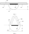
- FIG. 1 is a schematic structural diagram of a foldable mechanism in the related art in an unfolded state.
- the foldable mechanism mainly includes a shaft seat 310, a middle door plate 320, and two outer door plates 330.
- the two outer door plates 330 are respectively located at two sides of a central axis of the shaft seat 310 and are pivotally connected to the shaft seat 310 respectively, and the middle door plate 320 is located between the two outer door plates 330, and has a plate surface that is close to the shaft seat 310 and that is connected to the shaft seat 310.
- the outer support plate 211 and the bottom seat 11 there is a spacing between the outer support plate 211 and the bottom seat 11, which provides an enough space for the flipping of the outer support plate 211, thereby preventing the outer support plate 211 from interfering and colliding with the bottom seat 11 during the flipping.
- One portion of the support arm 212 is located between the outer support plate 211 and the bottom seat 11, to connect the support arm 212 and the outer support plate 211.
- Another portion of the support arm 212 is located between the inner plate member 22 and the bottom seat 11, so that the support arm 212 lifts the inner plate member 22, thereby stably supporting the flexible screen 200.
- a part between the two portions of the support arm 212 is pivotally connected to the hinge seat 12, so that support arm 212 rotates around its own pivotal axis.
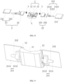
- FIG. 9 is a schematic structural diagram of a foldable mechanism. A viewing angle of FIG. 9 is opposite to that of FIG. 6 .
- FIG. 9 is a bottom view, while FIG. 6 is a top view.
- the outer support plate 211 includes an outer support plate body 2111 and a socket 2112.
- the socket 2112 is connected to a plate surface of the outer support plate body 2111 close to the bottom seat 11, and the support arm 212 is inserted into the socket 2112.
- the socket 2112 provides an insertion basis for the support arm 212, so that the support arm 212 can be inserted on the plate surface of the outer support plate body 2111 facing toward the bottom seat 11. In this way, a joint between the support arm 212 and the outer support plate 211 can be prevented from affecting support of the flexible screen 200 by the outer support plate 211, so that the flexible screen 200 can be stably supported.
- the outer support plate body 2111 and the socket 2112 are an integral structural member, which not only improves the manufacturing efficiency of the outer support plate 211, but also ensures the structural integrity of the outer support plate 211 and improves the structural strength.
- the socket 2112 includes a flange plate and a cylinder, one plate surface of the flange plate is connected to the outer support plate body 2111, an other, opposite plate surface of the flange plate is connected to an outer wall of the cylinder, and an axis of the cylinder is parallel to the outer support plate body 2111.
- the area of a connection between the socket 2112 and the outer support plate body 2111 is increased by using the flange plate, to improve the stability of the connection between the socket 2112 and the outer support plate body 2111.
- the flange plate and the outer support plate body 2111 are connected to each other by screws.
- the flange plate and the outer support plate body 2111 may alternatively be connected by bonding. This is not limited in this application.
- the first arm body 2121, the hinge cylinder 2122, and the second arm body 2123 are an integral structural member, which not only improves the manufacturing efficiency of the support arm 212, but also ensures the structural integrity of the support arm 212 and improves the structural strength.
- the hinge cylinder 2122 partially protrudes from the first arm body 2121 and the second arm body 2123, so that the hinge cylinder 2122 is located at a side of the first arm body 2121 facing toward the outer support plate body 2111 and a side of the second arm body 2123 facing toward the inner plate member 22.
- the first arm body 2121 can be conveniently located between the outer support plate body 2111 and the bottom seat 11
- the second arm body 2123 can be conveniently located between the inner plate member 22 and the bottom seat 11, so that the support arm 212 is more compactly arranged in the foldable mechanism.
- the outer plate member 21 and the inner plate member 22 are respectively described above, and it is learned that the outer plate member 21 and the inner plate member 22 can flip relative to the bottom seat 11 while always supporting the flexible screen 200 stably. It may be learned from the above that the outer plate member 21 is manually flipped by the user, and the inner plate member 22 is flipped by the driving assembly 3. Therefore, the driving assembly 3 is further described below.
- the driving assembly 3 includes an elastic member 31, and one portion of the elastic member 31 is connected to the bottom seat 11, and another portion is connected to a part of the inner plate member 22 close to the central axis L of the bottom seat 11.
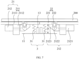
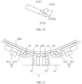
- a work process of the driving assembly 3 is described below with reference to FIG. 7 , FIG. 11 , and FIG. 12 .
- the elastic member 31 When the foldable mechanism is in the unfolded state (referring to FIG. 7 ), the elastic member 31 is in a stretched state and stores elastic potential energy by itself. Under the action of the elastic member 31, the inner plate member 22 has a tendency to flip toward the bottom seat 11.
- the middle portion of the support arm 212 is pivotally connected to the hinge seat 12, the first end of the support arm 212 is connected to the outer support plate 211, and the second end of the support arm 212 is in contact with the plate surface of the inner plate member 22 facing toward the bottom seat 11. Therefore, the support arm 212 is equivalent to a lever.
- the elastic members 31 are still in the stretched state, and the two inner plate members 22 remain tilted to each other under the action of the elastic members 31, to ensure continuous existence of a concave space A, thereby stably accommodating a bending part 210 of the flexible screen 200.
- the foldable mechanism When the flexible screen 200 is borne by the foldable mechanism provided in this implementation of this application, if the screen needs to be operated or viewed, the foldable mechanism remains in the unfolded state, and in this case, the two inner plate members 22 and the two outer plate members 21 are located in the same plane, to stably support the flexible screen 200 (referring to FIG. 7 ).
- the concave space A provides the space basis for accommodating the bending part 210 of the flexible screen 200
- the bending part 210 of the flexible screen 200 can be accommodated in the concave space A. In this way, the size of the flexible screen 200 located outside the concave space A is reduced, which is conducive to the miniaturized design.
- this implementation further provides another implementation of the driving assembly 3.
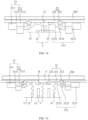
- FIG. 14 is a schematic structural diagram of a foldable mechanism in an unfolded state.
- the driving assembly 3 includes a first magnet 32 and a second magnet 33, and the first magnet 32 and the second magnet 33 are opposite to each other and are close to the central axis L of the bottom seat 11.
- the first magnet 32 is connected to the bottom seat 11.
- Second magnets 33 correspond to and are connected to the inner plate members 22 one to one. Portions of the first magnet 32 and the second magnet 33 opposite to each other have different magnetic poles.
- the inner plate member 22 can be pulled to move toward the bottom seat 11, to form the concave space A at the angle between the two inner plate members 22.
- the first magnet 32 and the second magnet 33 are attracted to each other, and the inner plate member 22 has a tendency to flip toward the bottom seat 11 under the action of the magnetic force.
- the inner plate member 22 remains stationary under the lifting action of the support arm 212, and is in the same plane as the outer plate member 21, to stably support the flexible screen 200.
- the two outer plate members 21 are flipped facing away from the bottom seat 11 around their own pivotal axes, to release the support arms 212 from lifting the inner plate members 22, and first magnet 32 and second magnet 33 are attracted to each other, to pull the corresponding inner plate member 22 to flip toward the bottom seat 11, so that the foldable mechanism is gradually transformed from the unfolded state to the folded state.
- both the first magnet 32 and the second magnet 33 are permanent magnets, to ensure that there is always a magnetic attraction force between the first magnet 32 and the second magnet 33.
- the two first magnets 32 are an integral structural member, to better achieve the miniaturized design.
- the driving assemblies 3 always apply acting forces to the inner plate members 22, so that the inner plate members 22 always have a tendency to flip toward the bottom seat 11.
- the base assembly 1 further includes two stop ribs 13.
- the stop ribs 13 correspond to the inner plate members 22 one to one, the stop rib 13 is located between the bottom seat 11 and the corresponding inner plate member 22, a first end of the stop rib 13 is connected to the bottom seat 11, and a second end of the stop rib 13 extends toward the corresponding inner plate member 22 and is configured to come into contact with the part of the inner plate member 22 close to the central axis L of the bottom seat 11.
- a maximum angle by which the inner plate member 22 flips can be limited by using the stop rib 13, thereby limiting the volume of the concave space A, so that the volume of the concave space A can match the flexible screen 200, thereby better achieving the miniaturized design.
- the stop rib 13 is a strip-shaped structural member, and the stop rib 13, the bottom seat 11, and the hinge seat 12 are an integral structural member, which not only improve the manufacturing efficiency of the base assembly 1, but also ensure the structural integrity of the base assembly 1 and improve the structural strength.
- the second end of the stop rib 13 is a slope, and a plate surface of the inner plate member 22 facing toward the bottom seat 11 is attached to the slope of the stop rib 13 when the inner plate member 22 abuts against the stop rib 13.
- a contact area between the stop rib 13 and the inner plate member 22 can be increased, so that the stop rib 13 supports the inner plate member 22 more stably.
- the bending part 210 of the flexible screen 200 is supported by the two inner plate members 22 when the foldable mechanism is in the folded state. Because the two inner plate members 22 are in a tilted state in this case, the two inner plate members 22 support two sides of the bending part 210 of the flexible screen 200 more.
- the inner plate member 22 further includes a tray 223, and the tray 223 is connected to a side edge of the inner support plate 221 close to the central axis L of the bottom seat 11.
- the foldable mechanism further includes a middle plate member 4 and a middle elastic member 5.
- the middle plate member 4 is located in the accommodation space B, one plate surface of the middle plate member 4 is in contact with the two trays 223, and an other, opposite plate surface of the middle plate member 4 is configured to come into contact with the bending part 210 of the flexible screen 200.
- the middle elastic member 5 is connected respectively to and between the middle plate member 4 and the bottom seat 11.
- the middle plate member 4 when the foldable mechanism is in the unfolded state, the middle plate member 4, the two inner plate members 22, and the two outer plate members 21 are located in the same plane, to support the flexible screen 200.
- the flexible screen 200 can remain flat for a user to operate, view, and so on.
- FIG. 16 is a schematic structural diagram of the foldable mechanism in a folding process.
- the two outer plate members 21 are flipped facing away from the bottom seat 11 around their own pivotal axes, so that the driving assemblies 3 can drive the corresponding inner plate members 22 to flip toward the bottom seat 11.
- the middle elastic member 5 can drive the middle plate member 4 to move toward the bottom seat 11, and the foldable mechanism is gradually transformed from the unfolded state to the folded state.
- FIG. 17 is a schematic structural diagram of the foldable mechanism in a folded state.
- the driving assemblies 3 respectively drive the corresponding inner plate members 22 to flip toward the bottom seat 11, to form the concave space A for accommodating the bending part 210 of the flexible screen 200 at the angle between the two inner plate members 22.
- the middle elastic member 5 drives the middle plate member 4 to move toward the bottom seat 11, so that the middle plate member 4 is located in the concave space A and is configured to come into contact with the bending part 210 of the flexible screen 200.
- the middle plate member 4 can be pulled toward the bottom seat 11 under the action of the middle elastic member 5, so that the middle plate member 4 is located in the concave space A and can come into contact with the bending part 210 of the flexible screen 200. In this way, a contact area between the foldable mechanism and the bending part 210 of the flexible screen 200 is increased, so that the bending part 210 of the flexible screen 200 is supported more stably.
- the middle elastic member 5 is a spiral spring.
Landscapes
- Engineering & Computer Science (AREA)
- Computer Hardware Design (AREA)
- Theoretical Computer Science (AREA)
- Physics & Mathematics (AREA)
- Signal Processing (AREA)
- Human Computer Interaction (AREA)
- General Engineering & Computer Science (AREA)
- General Physics & Mathematics (AREA)
- Mathematical Physics (AREA)
- Telephone Set Structure (AREA)
Claims (11)
- Zusammenklappbarer Mechanismus, umfassend eine Basisanordnung (1), zwei Stützanordnungen (2) und zwei Antriebsanordnungen (3), wobeidie Basisanordnung (1) einen unteren Sitz (11) und zwei Scharniersitze (12) umfasst, und die zwei Scharniersitze (12) jeweils an zwei Seiten des unteren Sitzes (11) befestigt sind;die zwei Stützanordnungen (2) sich jeweils an zwei Seiten einer Mittelachse (L) des unteren Sitzes (11) befinden, wobei jede Stützanordnung (2) ein äußeres Plattenelement (21) und ein inneres Plattenelement (22) umfasst, wobei sich die zwei inneren Plattenelemente (22) zwischen den zwei äußeren Plattenelementen (21) befinden, jedes äußere Plattenelement (21) und das entsprechende innere Plattenelement (22) mit dem entsprechenden Scharniersitz (12) schwenkbar verbunden sind, und Schwenkachsen der äußeren Plattenelemente (21) und der inneren Plattenelemente (22) parallel zu der Mittelachse (L) des unteren Sitzes (11) sind;die zwei Antriebsanordnungen (3) sich jeweils an den zwei Seiten der Mittelachse (L) des unteren Sitzes (11) befinden, und jede Antriebsanordnung (3) mit und zwischen dem unteren Sitz (11) und dem inneren Plattenelement (22) verbunden ist, das der Antriebsanordnung (3) entspricht; undin einem Fall, in dem der zusammenklappbare Mechanismus in einem zusammengeklappten Zustand ist, die Antriebsanordnungen (3) jeweils die entsprechenden inneren Plattenelemente (22) antreiben, um sich zu dem unteren Sitz (11) hin umzulegen, um einen konkaven Raum (A) zum Aufnehmen eines Biegeteils (210) eines flexiblen Bildschirms (200) in einem Winkel zwischen den zwei inneren Plattenelementen (22) auszubilden;wobei die Basisanordnung (1) ferner zwei Anschlagrippen (13) umfasst; unddie Anschlagrippen (13) den inneren Plattenelementen (22) eins zu eins entsprechen, wobei sich die Anschlagrippe (13) zwischen dem unteren Sitz (11) und dem entsprechenden inneren Plattenelement (22) befindet, ein erstes Ende der Anschlagrippe (13) mit dem unteren Sitz (11) verbunden ist, und ein zweites Ende der Anschlagrippe (13) konfiguriert ist, um mit dem Teil des inneren Plattenelements (22) nahe der Mittelachse (L) des unteren Sitzes (11) in Kontakt zu kommen.
- Zusammenklappbarer Mechanismus nach Anspruch 1, wobei die Antriebsanordnung (3) ein elastisches Element (31) umfasst; und
ein Abschnitt des elastischen Elements (31) mit dem unteren Sitz (11) verbunden ist, und ein anderer Abschnitt mit einem Teil des inneren Plattenelements (22) nahe der Mittelachse (L) des unteren Sitzes (11) verbunden ist. - Zusammenklappbarer Mechanismus nach Anspruch 1, wobei die Antriebsanordnung (3) einen ersten Magneten (32) und einen zweiten Magneten (33) umfasst, und der erste Magnet (32) und der zweite Magnet (33) einander gegenüberliegen liegen und nahe der Mittelachse (L) des unteren Sitzes (11) sind;der erste Magnet (32) mit dem unteren Sitz (11) verbunden ist; undder zweite Magnet (33) mit dem inneren Plattenelement (22) verbunden ist, und Abschnitte des ersten Magneten (32) und des zweiten Magneten (33), die einander gegenüberliegen, Magnetpole aufweisen.
- Zusammenklappbarer Mechanismus nach einem der Ansprüche 1 bis 3, wobei das innere Plattenelement (22) eine innere Stützplatte (221) und einen Scharnierzapfen (222) umfasst;es einen Abstand (D) zwischen der inneren Stützplatte (221) und dem unteren Sitz (11) gibt; undder Scharnierzapfen (222) mit einer Seitenkante der inneren Stützplatte (221) nahe dem äußeren Plattenelement (21) verbunden ist, und der Scharnierzapfen (222) mit dem Scharniersitz (12) schwenkbar verbunden ist.
- Zusammenklappbarer Mechanismus nach Anspruch 4, wobei das innere Plattenelement (22) ferner eine Ablage (223) umfasst;die Ablage (223) mit einer Seitenkante der inneren Stützplatte (221) nahe der Mittelachse (L) des unteren Sitzes (11) verbunden ist, und zwei Ablagen (223) einander gegenüberliegen und einen Aufnahmeraum (B) ausbilden;der zusammenklappbare Mechanismus ferner ein mittleres Plattenelement (4) und ein mittleres elastisches Element (5) umfasst;das mittlere Plattenelement (4) sich in dem Aufnahmeraum (B) befindet, eine Plattenoberfläche des mittleren Plattenelements (4) in Kontakt mit den zwei Ablagen (223) ist, und eine andere, gegenüberliegende Plattenoberfläche des mittleren Plattenelements (4) konfiguriert ist, um mit dem Biegeteil (210) des flexiblen Bildschirms (200) in Kontakt zu kommen; unddas mittlere elastische Element (5) jeweils mit und zwischen dem mittleren Plattenelement (4) und dem unteren Sitz (11) verbunden ist.
- Zusammenklappbarer Mechanismus nach einem der Ansprüche 1 bis 5, wobei das äußere Plattenelement (21) eine äußere Stützplatte (211) und einen Stützarm (212) umfasst; und
sich der Stützarm (212) zwischen der äußeren Stützplatte (211) und dem unteren Sitz (11) und zwischen dem inneren Plattenelement (22) und dem unteren Sitz (11) befindet, ein mittlerer Abschnitt des Stützarms (212) mit dem Scharniersitz (12) schwenkbar verbunden ist, ein erstes Ende des Stützarms (212) mit der äußeren Stützplatte (211) verbunden ist, und ein zweites Ende des Stützarms (212) mit einer Plattenoberfläche des inneren Plattenelements (22) in Kontakt ist, das dem unteren Sitz (11) zugewandt ist. - Zusammenklappbarer Mechanismus nach Anspruch 6, wobei die äußere Stützplatte (211) einen äußeren Stützplattenkörper (2111) und eine Buchse (2112) umfasst; und
die Buchse (2112) mit einer Plattenoberfläche des äußeren Stützplattenkörpers (2111) nahe dem unteren Sitz (11) verbunden ist, und der Stützarm (212) in die Buchse (2112) eingesetzt ist. - Zusammenklappbarer Mechanismus nach Anspruch 7, wobei der Stützarm (212) einen ersten Armkörper (2121), einen Scharnierzylinder (2122) und einen zweiten Armkörper (2123) umfasst, die der Reihe nach verbunden sind;der erste Armkörper (2121) in die Buchse (2112) eingeführt ist;der zweite Armkörper (2123) in Kontakt mit einer Plattenoberfläche des inneren Plattenelements (22) nahe dem Bodensitz (11) ist; undsich der Scharnierzylinder (2122) zwischen dem äußeren Stützplattenkörper (2111) und dem inneren Plattenelement (22) befindet, und mit dem Scharniersitz (12) schwenkbar verbunden ist.
- Zusammenklappbarer Mechanismus nach Anspruch 8, wobei ein Teil des zweiten Armkörpers (2123), der in Kontakt mit dem inneren Plattenelement (22) ist, eine trapezförmige Oberfläche (2123a) ist, eine obere Unterkante der trapezförmigen Oberfläche (2123a) mit dem Scharnierzylinder (2122) verbunden ist, und die trapezförmige Oberfläche (2123a) an dem inneren Plattenelement (22) angebracht ist.
- Zusammenklappbarer Mechanismus nach einem der Ansprüche 1 bis 9, wobei für dieselbe Stützanordnung (2) die Drehachse des äußeren Plattenelements (21) und die Drehachse des inneren Plattenelements (22) koaxial sind.
- Mobiles Endgerät, umfassend einen zusammenklappbaren Mechanismus (100) und einen flexiblen Bildschirm (200), wobeider zusammenklappbare Mechanismus (100) der zusammenklappbare Mechanismus nach einem der Ansprüche 1 bis 10 ist; undder flexible Bildschirm (200) an den zwei inneren Plattenelementen (22) beziehungsweise den zwei äußeren Plattenelementen (21) angebracht ist.
Applications Claiming Priority (2)
| Application Number | Priority Date | Filing Date | Title |
|---|---|---|---|
| CN202110286914.9A CN113890911B (zh) | 2021-03-17 | 2021-03-17 | 折叠机构和移动终端 |
| PCT/CN2022/075036 WO2022193864A1 (zh) | 2021-03-17 | 2022-01-29 | 折叠机构和移动终端 |
Publications (3)
| Publication Number | Publication Date |
|---|---|
| EP4089989A1 EP4089989A1 (de) | 2022-11-16 |
| EP4089989A4 EP4089989A4 (de) | 2023-08-02 |
| EP4089989B1 true EP4089989B1 (de) | 2024-07-03 |
Family
ID=79013124
Family Applications (1)
| Application Number | Title | Priority Date | Filing Date |
|---|---|---|---|
| EP22733500.7A Active EP4089989B1 (de) | 2021-03-17 | 2022-01-29 | Faltmechanismus und mobiles endgerät |
Country Status (4)
| Country | Link |
|---|---|
| US (1) | US12216500B2 (de) |
| EP (1) | EP4089989B1 (de) |
| CN (1) | CN113890911B (de) |
| WO (1) | WO2022193864A1 (de) |
Families Citing this family (4)
| Publication number | Priority date | Publication date | Assignee | Title |
|---|---|---|---|---|
| WO2022097525A1 (ja) * | 2020-11-09 | 2022-05-12 | 株式会社村田製作所 | 電子機器 |
| CN113890911B (zh) | 2021-03-17 | 2022-11-08 | 荣耀终端有限公司 | 折叠机构和移动终端 |
| CN117449715A (zh) * | 2022-07-18 | 2024-01-26 | 深圳富泰宏精密工业有限公司 | 铰链结构以及终端装置 |
| CN117456837A (zh) * | 2023-11-30 | 2024-01-26 | 联想(北京)有限公司 | 电子设备 |
Family Cites Families (12)
| Publication number | Priority date | Publication date | Assignee | Title |
|---|---|---|---|---|
| KR102322377B1 (ko) * | 2014-12-31 | 2021-11-05 | 엘지디스플레이 주식회사 | 접이식 디스플레이 장치 |
| CN108173995A (zh) * | 2018-01-08 | 2018-06-15 | 杭州安费诺飞凤通信部品有限公司 | 一种内折柔性屏移动终端铰链及内折柔性屏移动终端 |
| CN207977988U (zh) * | 2018-01-08 | 2018-10-16 | 杭州安费诺飞凤通信部品有限公司 | 一种内折柔性屏移动终端铰链及内折柔性屏移动终端 |
| CN208190691U (zh) | 2018-01-08 | 2018-12-04 | 杭州安费诺飞凤通信部品有限公司 | 半自动内折柔性屏移动终端铰链及内折柔性屏移动终端 |
| CN108322567B (zh) * | 2018-02-01 | 2019-11-08 | 杭州安费诺飞凤通信部品有限公司 | 一种内折柔性屏移动终端的铰链及内折柔性屏移动终端 |
| WO2019210766A1 (en) * | 2018-05-02 | 2019-11-07 | Guangdong Oppo Mobile Telecommunications Corp., Ltd. | Foldable screen assembly and electronic device |
| US10491725B1 (en) * | 2018-09-14 | 2019-11-26 | Motorola Mobility Llc | Hinged electronic device with moving support plates for a flexible display and corresponding systems |
| CN109780403B (zh) | 2019-01-29 | 2020-08-18 | 维沃移动通信有限公司 | 转动连接组件及折叠式终端设备 |
| CN110714979B (zh) | 2019-11-15 | 2024-05-24 | 东莞市宏联电子有限公司 | 一种转动装置和柔性屏装置 |
| CN113282136B (zh) * | 2020-02-20 | 2024-01-30 | 北京小米移动软件有限公司 | 铰链结构和折叠式电子设备 |
| CN212624631U (zh) | 2020-08-18 | 2021-02-26 | Oppo广东移动通信有限公司 | 折叠机构和具有其的电子设备 |
| CN113890911B (zh) | 2021-03-17 | 2022-11-08 | 荣耀终端有限公司 | 折叠机构和移动终端 |
-
2021
- 2021-03-17 CN CN202110286914.9A patent/CN113890911B/zh active Active
-
2022
- 2022-01-29 EP EP22733500.7A patent/EP4089989B1/de active Active
- 2022-01-29 US US17/790,717 patent/US12216500B2/en active Active
- 2022-01-29 WO PCT/CN2022/075036 patent/WO2022193864A1/zh not_active Ceased
Also Published As
| Publication number | Publication date |
|---|---|
| EP4089989A4 (de) | 2023-08-02 |
| CN113890911A (zh) | 2022-01-04 |
| US12216500B2 (en) | 2025-02-04 |
| WO2022193864A1 (zh) | 2022-09-22 |
| US20240201740A1 (en) | 2024-06-20 |
| EP4089989A1 (de) | 2022-11-16 |
| CN113890911B (zh) | 2022-11-08 |
Similar Documents
| Publication | Publication Date | Title |
|---|---|---|
| US12216500B2 (en) | Foldable mechanism and mobile terminal | |
| CN110661951B (zh) | 摄像模组及电子设备 | |
| EP4220001A1 (de) | Faltbare halterung und elektronische vorrichtung | |
| CN102347160B (zh) | 开关及电子设备 | |
| EP3239967A1 (de) | Flexible bildschirmkomponente und endgerät | |
| US20250048572A1 (en) | Hinge mechanism and electronic device | |
| US12556625B2 (en) | Rotating shaft mechanism and terminal device | |
| EP2285075A1 (de) | Elektronische Vorrichtung | |
| CN112991958A (zh) | 电子设备 | |
| KR102638435B1 (ko) | 힌지 및 인폴딩 플렉서블 스크린 이동 단말기 | |
| US20250275073A1 (en) | Hinge Mechanism and Electronic Device | |
| CN102386014B (zh) | 开关及电子设备 | |
| CN115764458A (zh) | 适配器及具有其的轨道式插座 | |
| EP4529146A1 (de) | Faltanordnung und elektronische vorrichtung | |
| CN101796737A (zh) | 用于移动电话的转动铰链 | |
| CN219696272U (zh) | 一种双电源自动转换开关 | |
| CN219755090U (zh) | 转轴机构、可折叠壳体及可折叠电子设备 | |
| WO2024169202A1 (zh) | 转轴机构及终端设备 | |
| WO2024140452A1 (zh) | 铰链组件及电子设备 | |
| CN114992434B (zh) | 电子设备支架 | |
| US20240427387A1 (en) | Hinge mechanism and electronic device | |
| CN114125092B (zh) | 移动终端 | |
| WO2025001204A1 (zh) | 一种转轴机构及电子设备 | |
| CN223414894U (zh) | 终端设备 | |
| CN115875916B (zh) | 双向开门制冷设备 |
Legal Events
| Date | Code | Title | Description |
|---|---|---|---|
| STAA | Information on the status of an ep patent application or granted ep patent |
Free format text: STATUS: UNKNOWN |
|
| STAA | Information on the status of an ep patent application or granted ep patent |
Free format text: STATUS: THE INTERNATIONAL PUBLICATION HAS BEEN MADE |
|
| PUAI | Public reference made under article 153(3) epc to a published international application that has entered the european phase |
Free format text: ORIGINAL CODE: 0009012 |
|
| STAA | Information on the status of an ep patent application or granted ep patent |
Free format text: STATUS: REQUEST FOR EXAMINATION WAS MADE |
|
| 17P | Request for examination filed |
Effective date: 20220705 |
|
| AK | Designated contracting states |
Kind code of ref document: A1 Designated state(s): AL AT BE BG CH CY CZ DE DK EE ES FI FR GB GR HR HU IE IS IT LI LT LU LV MC MK MT NL NO PL PT RO RS SE SI SK SM TR |
|
| A4 | Supplementary search report drawn up and despatched |
Effective date: 20230629 |
|
| RIC1 | Information provided on ipc code assigned before grant |
Ipc: G06F 1/16 20060101ALI20230623BHEP Ipc: H04M 1/02 20060101AFI20230623BHEP |
|
| GRAP | Despatch of communication of intention to grant a patent |
Free format text: ORIGINAL CODE: EPIDOSNIGR1 |
|
| STAA | Information on the status of an ep patent application or granted ep patent |
Free format text: STATUS: GRANT OF PATENT IS INTENDED |
|
| DAV | Request for validation of the european patent (deleted) | ||
| DAX | Request for extension of the european patent (deleted) | ||
| INTG | Intention to grant announced |
Effective date: 20240129 |
|
| GRAS | Grant fee paid |
Free format text: ORIGINAL CODE: EPIDOSNIGR3 |
|
| GRAA | (expected) grant |
Free format text: ORIGINAL CODE: 0009210 |
|
| STAA | Information on the status of an ep patent application or granted ep patent |
Free format text: STATUS: THE PATENT HAS BEEN GRANTED |
|
| AK | Designated contracting states |
Kind code of ref document: B1 Designated state(s): AL AT BE BG CH CY CZ DE DK EE ES FI FR GB GR HR HU IE IS IT LI LT LU LV MC MK MT NL NO PL PT RO RS SE SI SK SM TR |
|
| REG | Reference to a national code |
Ref country code: CH Ref legal event code: EP |
|
| REG | Reference to a national code |
Ref country code: DE Ref legal event code: R096 Ref document number: 602022004363 Country of ref document: DE |
|
| REG | Reference to a national code |
Ref country code: NL Ref legal event code: FP |
|
| REG | Reference to a national code |
Ref country code: LT Ref legal event code: MG9D |
|
| PG25 | Lapsed in a contracting state [announced via postgrant information from national office to epo] |
Ref country code: PT Free format text: LAPSE BECAUSE OF FAILURE TO SUBMIT A TRANSLATION OF THE DESCRIPTION OR TO PAY THE FEE WITHIN THE PRESCRIBED TIME-LIMIT Effective date: 20241104 |
|
| REG | Reference to a national code |
Ref country code: AT Ref legal event code: MK05 Ref document number: 1700969 Country of ref document: AT Kind code of ref document: T Effective date: 20240703 |
|
| PG25 | Lapsed in a contracting state [announced via postgrant information from national office to epo] |
Ref country code: PT Free format text: LAPSE BECAUSE OF FAILURE TO SUBMIT A TRANSLATION OF THE DESCRIPTION OR TO PAY THE FEE WITHIN THE PRESCRIBED TIME-LIMIT Effective date: 20241104 |
|
| PG25 | Lapsed in a contracting state [announced via postgrant information from national office to epo] |
Ref country code: NO Free format text: LAPSE BECAUSE OF FAILURE TO SUBMIT A TRANSLATION OF THE DESCRIPTION OR TO PAY THE FEE WITHIN THE PRESCRIBED TIME-LIMIT Effective date: 20241003 |
|
| PG25 | Lapsed in a contracting state [announced via postgrant information from national office to epo] |
Ref country code: GR Free format text: LAPSE BECAUSE OF FAILURE TO SUBMIT A TRANSLATION OF THE DESCRIPTION OR TO PAY THE FEE WITHIN THE PRESCRIBED TIME-LIMIT Effective date: 20241004 Ref country code: FI Free format text: LAPSE BECAUSE OF FAILURE TO SUBMIT A TRANSLATION OF THE DESCRIPTION OR TO PAY THE FEE WITHIN THE PRESCRIBED TIME-LIMIT Effective date: 20240703 Ref country code: PL Free format text: LAPSE BECAUSE OF FAILURE TO SUBMIT A TRANSLATION OF THE DESCRIPTION OR TO PAY THE FEE WITHIN THE PRESCRIBED TIME-LIMIT Effective date: 20240703 |
|
| PG25 | Lapsed in a contracting state [announced via postgrant information from national office to epo] |
Ref country code: BG Free format text: LAPSE BECAUSE OF FAILURE TO SUBMIT A TRANSLATION OF THE DESCRIPTION OR TO PAY THE FEE WITHIN THE PRESCRIBED TIME-LIMIT Effective date: 20240703 |
|
| PG25 | Lapsed in a contracting state [announced via postgrant information from national office to epo] |
Ref country code: LV Free format text: LAPSE BECAUSE OF FAILURE TO SUBMIT A TRANSLATION OF THE DESCRIPTION OR TO PAY THE FEE WITHIN THE PRESCRIBED TIME-LIMIT Effective date: 20240703 |
|
| PG25 | Lapsed in a contracting state [announced via postgrant information from national office to epo] |
Ref country code: IS Free format text: LAPSE BECAUSE OF FAILURE TO SUBMIT A TRANSLATION OF THE DESCRIPTION OR TO PAY THE FEE WITHIN THE PRESCRIBED TIME-LIMIT Effective date: 20241103 Ref country code: AT Free format text: LAPSE BECAUSE OF FAILURE TO SUBMIT A TRANSLATION OF THE DESCRIPTION OR TO PAY THE FEE WITHIN THE PRESCRIBED TIME-LIMIT Effective date: 20240703 |
|
| PG25 | Lapsed in a contracting state [announced via postgrant information from national office to epo] |
Ref country code: HR Free format text: LAPSE BECAUSE OF FAILURE TO SUBMIT A TRANSLATION OF THE DESCRIPTION OR TO PAY THE FEE WITHIN THE PRESCRIBED TIME-LIMIT Effective date: 20240703 Ref country code: CZ Free format text: LAPSE BECAUSE OF FAILURE TO SUBMIT A TRANSLATION OF THE DESCRIPTION OR TO PAY THE FEE WITHIN THE PRESCRIBED TIME-LIMIT Effective date: 20240703 |
|
| PG25 | Lapsed in a contracting state [announced via postgrant information from national office to epo] |
Ref country code: ES Free format text: LAPSE BECAUSE OF FAILURE TO SUBMIT A TRANSLATION OF THE DESCRIPTION OR TO PAY THE FEE WITHIN THE PRESCRIBED TIME-LIMIT Effective date: 20240703 Ref country code: RS Free format text: LAPSE BECAUSE OF FAILURE TO SUBMIT A TRANSLATION OF THE DESCRIPTION OR TO PAY THE FEE WITHIN THE PRESCRIBED TIME-LIMIT Effective date: 20241003 |
|
| PG25 | Lapsed in a contracting state [announced via postgrant information from national office to epo] |
Ref country code: RS Free format text: LAPSE BECAUSE OF FAILURE TO SUBMIT A TRANSLATION OF THE DESCRIPTION OR TO PAY THE FEE WITHIN THE PRESCRIBED TIME-LIMIT Effective date: 20241003 Ref country code: PL Free format text: LAPSE BECAUSE OF FAILURE TO SUBMIT A TRANSLATION OF THE DESCRIPTION OR TO PAY THE FEE WITHIN THE PRESCRIBED TIME-LIMIT Effective date: 20240703 Ref country code: NO Free format text: LAPSE BECAUSE OF FAILURE TO SUBMIT A TRANSLATION OF THE DESCRIPTION OR TO PAY THE FEE WITHIN THE PRESCRIBED TIME-LIMIT Effective date: 20241003 Ref country code: LV Free format text: LAPSE BECAUSE OF FAILURE TO SUBMIT A TRANSLATION OF THE DESCRIPTION OR TO PAY THE FEE WITHIN THE PRESCRIBED TIME-LIMIT Effective date: 20240703 Ref country code: IS Free format text: LAPSE BECAUSE OF FAILURE TO SUBMIT A TRANSLATION OF THE DESCRIPTION OR TO PAY THE FEE WITHIN THE PRESCRIBED TIME-LIMIT Effective date: 20241103 Ref country code: HR Free format text: LAPSE BECAUSE OF FAILURE TO SUBMIT A TRANSLATION OF THE DESCRIPTION OR TO PAY THE FEE WITHIN THE PRESCRIBED TIME-LIMIT Effective date: 20240703 Ref country code: GR Free format text: LAPSE BECAUSE OF FAILURE TO SUBMIT A TRANSLATION OF THE DESCRIPTION OR TO PAY THE FEE WITHIN THE PRESCRIBED TIME-LIMIT Effective date: 20241004 Ref country code: FI Free format text: LAPSE BECAUSE OF FAILURE TO SUBMIT A TRANSLATION OF THE DESCRIPTION OR TO PAY THE FEE WITHIN THE PRESCRIBED TIME-LIMIT Effective date: 20240703 Ref country code: ES Free format text: LAPSE BECAUSE OF FAILURE TO SUBMIT A TRANSLATION OF THE DESCRIPTION OR TO PAY THE FEE WITHIN THE PRESCRIBED TIME-LIMIT Effective date: 20240703 Ref country code: CZ Free format text: LAPSE BECAUSE OF FAILURE TO SUBMIT A TRANSLATION OF THE DESCRIPTION OR TO PAY THE FEE WITHIN THE PRESCRIBED TIME-LIMIT Effective date: 20240703 Ref country code: BG Free format text: LAPSE BECAUSE OF FAILURE TO SUBMIT A TRANSLATION OF THE DESCRIPTION OR TO PAY THE FEE WITHIN THE PRESCRIBED TIME-LIMIT Effective date: 20240703 Ref country code: AT Free format text: LAPSE BECAUSE OF FAILURE TO SUBMIT A TRANSLATION OF THE DESCRIPTION OR TO PAY THE FEE WITHIN THE PRESCRIBED TIME-LIMIT Effective date: 20240703 |
|
| REG | Reference to a national code |
Ref country code: DE Ref legal event code: R097 Ref document number: 602022004363 Country of ref document: DE |
|
| PG25 | Lapsed in a contracting state [announced via postgrant information from national office to epo] |
Ref country code: DK Free format text: LAPSE BECAUSE OF FAILURE TO SUBMIT A TRANSLATION OF THE DESCRIPTION OR TO PAY THE FEE WITHIN THE PRESCRIBED TIME-LIMIT Effective date: 20240703 Ref country code: SM Free format text: LAPSE BECAUSE OF FAILURE TO SUBMIT A TRANSLATION OF THE DESCRIPTION OR TO PAY THE FEE WITHIN THE PRESCRIBED TIME-LIMIT Effective date: 20240703 Ref country code: RO Free format text: LAPSE BECAUSE OF FAILURE TO SUBMIT A TRANSLATION OF THE DESCRIPTION OR TO PAY THE FEE WITHIN THE PRESCRIBED TIME-LIMIT Effective date: 20240703 |
|
| PG25 | Lapsed in a contracting state [announced via postgrant information from national office to epo] |
Ref country code: EE Free format text: LAPSE BECAUSE OF FAILURE TO SUBMIT A TRANSLATION OF THE DESCRIPTION OR TO PAY THE FEE WITHIN THE PRESCRIBED TIME-LIMIT Effective date: 20240703 |
|
| PG25 | Lapsed in a contracting state [announced via postgrant information from national office to epo] |
Ref country code: SK Free format text: LAPSE BECAUSE OF FAILURE TO SUBMIT A TRANSLATION OF THE DESCRIPTION OR TO PAY THE FEE WITHIN THE PRESCRIBED TIME-LIMIT Effective date: 20240703 Ref country code: IT Free format text: LAPSE BECAUSE OF FAILURE TO SUBMIT A TRANSLATION OF THE DESCRIPTION OR TO PAY THE FEE WITHIN THE PRESCRIBED TIME-LIMIT Effective date: 20240703 |
|
| PLBE | No opposition filed within time limit |
Free format text: ORIGINAL CODE: 0009261 |
|
| STAA | Information on the status of an ep patent application or granted ep patent |
Free format text: STATUS: NO OPPOSITION FILED WITHIN TIME LIMIT |
|
| 26N | No opposition filed |
Effective date: 20250404 |
|
| REG | Reference to a national code |
Ref country code: CH Ref legal event code: PL |
|
| PG25 | Lapsed in a contracting state [announced via postgrant information from national office to epo] |
Ref country code: SE Free format text: LAPSE BECAUSE OF FAILURE TO SUBMIT A TRANSLATION OF THE DESCRIPTION OR TO PAY THE FEE WITHIN THE PRESCRIBED TIME-LIMIT Effective date: 20240703 |
|
| PG25 | Lapsed in a contracting state [announced via postgrant information from national office to epo] |
Ref country code: LU Free format text: LAPSE BECAUSE OF NON-PAYMENT OF DUE FEES Effective date: 20250129 Ref country code: MC Free format text: LAPSE BECAUSE OF FAILURE TO SUBMIT A TRANSLATION OF THE DESCRIPTION OR TO PAY THE FEE WITHIN THE PRESCRIBED TIME-LIMIT Effective date: 20240703 |
|
| PG25 | Lapsed in a contracting state [announced via postgrant information from national office to epo] |
Ref country code: BE Free format text: LAPSE BECAUSE OF NON-PAYMENT OF DUE FEES Effective date: 20250131 |
|
| PG25 | Lapsed in a contracting state [announced via postgrant information from national office to epo] |
Ref country code: FR Free format text: LAPSE BECAUSE OF NON-PAYMENT OF DUE FEES Effective date: 20250131 |
|
| PG25 | Lapsed in a contracting state [announced via postgrant information from national office to epo] |
Ref country code: CH Free format text: LAPSE BECAUSE OF NON-PAYMENT OF DUE FEES Effective date: 20250131 |
|
| REG | Reference to a national code |
Ref country code: BE Ref legal event code: MM Effective date: 20250131 |
|
| PGFP | Annual fee paid to national office [announced via postgrant information from national office to epo] |
Ref country code: GB Payment date: 20251211 Year of fee payment: 5 |
|
| PGFP | Annual fee paid to national office [announced via postgrant information from national office to epo] |
Ref country code: NL Payment date: 20251215 Year of fee payment: 5 |
|
| PG25 | Lapsed in a contracting state [announced via postgrant information from national office to epo] |
Ref country code: IE Free format text: LAPSE BECAUSE OF NON-PAYMENT OF DUE FEES Effective date: 20250129 |
|
| PGFP | Annual fee paid to national office [announced via postgrant information from national office to epo] |
Ref country code: DE Payment date: 20251203 Year of fee payment: 5 |