EP4089378B1 - Piezoelektrischer ultraschallgasdetektor - Google Patents
Piezoelektrischer ultraschallgasdetektor Download PDFInfo
- Publication number
- EP4089378B1 EP4089378B1 EP22177659.4A EP22177659A EP4089378B1 EP 4089378 B1 EP4089378 B1 EP 4089378B1 EP 22177659 A EP22177659 A EP 22177659A EP 4089378 B1 EP4089378 B1 EP 4089378B1
- Authority
- EP
- European Patent Office
- Prior art keywords
- piezoelectric element
- perforated metal
- metal electrodes
- gas detector
- protective cover
- Prior art date
- Legal status (The legal status is an assumption and is not a legal conclusion. Google has not performed a legal analysis and makes no representation as to the accuracy of the status listed.)
- Active
Links
Images

Classifications
-
- G—PHYSICS
- G01—MEASURING; TESTING
- G01L—MEASURING FORCE, STRESS, TORQUE, WORK, MECHANICAL POWER, MECHANICAL EFFICIENCY, OR FLUID PRESSURE
- G01L9/00—Measuring steady of quasi-steady pressure of fluid or fluent solid material by electric or magnetic pressure-sensitive elements; Transmitting or indicating the displacement of mechanical pressure-sensitive elements, used to measure the steady or quasi-steady pressure of a fluid or fluent solid material, by electric or magnetic means
- G01L9/08—Measuring steady of quasi-steady pressure of fluid or fluent solid material by electric or magnetic pressure-sensitive elements; Transmitting or indicating the displacement of mechanical pressure-sensitive elements, used to measure the steady or quasi-steady pressure of a fluid or fluent solid material, by electric or magnetic means by making use of piezoelectric devices, i.e. electric circuits therefor
-
- G—PHYSICS
- G01—MEASURING; TESTING
- G01M—TESTING STATIC OR DYNAMIC BALANCE OF MACHINES OR STRUCTURES; TESTING OF STRUCTURES OR APPARATUS, NOT OTHERWISE PROVIDED FOR
- G01M3/00—Investigating fluid-tightness of structures
- G01M3/02—Investigating fluid-tightness of structures by using fluid or vacuum
- G01M3/04—Investigating fluid-tightness of structures by using fluid or vacuum by detecting the presence of fluid at the leakage point
- G01M3/24—Investigating fluid-tightness of structures by using fluid or vacuum by detecting the presence of fluid at the leakage point using infrasonic, sonic, or ultrasonic vibrations
- G01M3/243—Investigating fluid-tightness of structures by using fluid or vacuum by detecting the presence of fluid at the leakage point using infrasonic, sonic, or ultrasonic vibrations for pipes
-
- G—PHYSICS
- G01—MEASURING; TESTING
- G01M—TESTING STATIC OR DYNAMIC BALANCE OF MACHINES OR STRUCTURES; TESTING OF STRUCTURES OR APPARATUS, NOT OTHERWISE PROVIDED FOR
- G01M3/00—Investigating fluid-tightness of structures
- G01M3/02—Investigating fluid-tightness of structures by using fluid or vacuum
- G01M3/26—Investigating fluid-tightness of structures by using fluid or vacuum by measuring rate of loss or gain of fluid, e.g. by pressure-responsive devices, by flow detectors
-
- G—PHYSICS
- G01—MEASURING; TESTING
- G01H—MEASUREMENT OF MECHANICAL VIBRATIONS OR ULTRASONIC, SONIC OR INFRASONIC WAVES
- G01H11/00—Measuring mechanical vibrations or ultrasonic, sonic or infrasonic waves by detecting changes in electric or magnetic properties
- G01H11/06—Measuring mechanical vibrations or ultrasonic, sonic or infrasonic waves by detecting changes in electric or magnetic properties by electric means
- G01H11/08—Measuring mechanical vibrations or ultrasonic, sonic or infrasonic waves by detecting changes in electric or magnetic properties by electric means using piezoelectric devices
Definitions
- Gas detectors may be used in areas where this potential for gas leaks.
- WO 2014/125242 A2 which relates to a sound sensor in the form of a compression assembly for detecting airborne sound, and comprises a piezoelectric crystal transducer, an electrode and a low density environmental seal.
- the present invention relates to an ultrasonic gas detector according to claim 1 and to a method for forming an ultrasonic gas detector according to claim 11.
- Leakage of gas from gas installations, pipe lines and their components might be very dangerous for the environment, as well as human and animal health, especially if the gas is toxic, flammable or corrosive. If such a gas leak happens, for example as an accident, it needs to be detected as soon as possible, and quantitatively measured to determine if the leak of gas is above an alarm threshold value. If the gas is above the threshold, the alarm may sound, allowing for safe evacuation. Additionally, some part of the gas installation may need to be switched off and insulated in order to stop the gas leak.
- gas leakages from pressurized source produce sound, which typically have frequencies in audible and ultrasonic range.
- An ultrasonic detector may be capable of detecting this ultrasound (at ultrasonic frequency), and therefore detect the gas leak.
- An ultrasonic detector would signal the level of this ultrasound, thereby triggering an alarm if the ultrasound level is above certain, preset threshold.
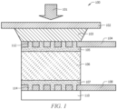
- the ultrasonic gas detector 100 comprises a piezoelectric element 106 operable to convert the pressure of sound waves from mechanical energy into electric signal.
- the ultrasonic sound waves coming from the environment are illustrated by the arrow 101.
- the ultrasonic detector 100 further comprises a protective cover 102, a hot melt adhesive 103 (which may be used as an acoustic filler), one or more perforated metal electrodes 104 and 108 with openings (holes and slots) 112 and 114 filled with solder, one or more layers of solder 105 and 107, the piezoelectric sensing element 106 comprising silver electrodes, and a support 110.
- the protective cover 102 comprises a low density material, such as Polytetrafluoroethylene (PTFE), polyethylene (PE), or another low density material.
- PTFE Polytetrafluoroethylene
- PE polyethylene
- One or more of the described elements may be attached to one another with adhesive.
- the piezoelectric element 106 is soldered to the perforated metal electrodes 104 and 108 that connect it to an electronic circuit. Perforation of the metal electrode(s) 104 and 108 allows the electrode(s) 104 and 108 to be attached to the piezoelectric element 106 in a way that provides stability for a broad range of temperatures, as these holes 112 and 114 are filled with solder material. Perforation also simplifies the soldering process, as the solder paste 105 and 107 penetrates easily through the perforated holes 112 and 114 and stops the silver electrode(s) of the piezoelectric element 106 from being dissolved in the solder during the soldering process.
- the hot melt adhesive 103 is used as acoustic filler for the space between the ultrasound exposed area of the piezoelectric element 106 and the protective cover 102.
- the molten hot melt material solidifies on contact with the piezoelectric element and casing, stopping leakage into the housing while maintaining excellent acoustic and waterproof sealing properties. Hot melt material cools in a matter of minutes allowing for a simpler manufacturing process.
- a piezoelectric element may be conductively connected to metal electrodes both with conductive glue and soldering. Applicants have discovered that perforated metal electrodes 104 and 108 soldered to the piezoelectric element 106 can survive multiple temperature shocks, which may relate to or demonstrate aging of device and the influence of the environment on it.
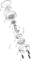
- the ultrasonic detector 200 may be similar to the ultrasonic detector 100 of FIG. 1 , wherein the ultrasonic detector 200 may comprise a piezoelectric element 206, a protective cover 202, a hot melt adhesive 203 (which may be used as an acoustic filler), one or more perforated metal electrodes 204 and 208 and a support 210, wherein these elements may be similar to the piezoelectric element 106, protective cover 102, hot melt adhesive 103, perforated metal electrodes 104 and 108, and support 110 described in FIG. 1 .
- the ultrasonic detector 200 comprises one or more casing elements 220 and 222 operable to enclose and house the other elements of the ultrasonic detector 200.
- the casing elements 220 and 222 may comprise a metal material and may be held together by one or more screws 224.
- the ultrasonic detector 200 may comprise a printed circuit board (PCB) 230 operable to receive ultrasonic data from the piezoelectric element 206 and electrodes 204 and 208, wherein the electrodes 204 and 208 may connect to, or contact, the PCB 230.
- the ultrasonic detector 200 comprises supporting elements and insulating elements for supporting and insulating the other elements of the ultrasonic detector 200.
- a foam support 226 may be located within the casing elements 200 and 222.
- an insulator 228 (which may be made of a plastic material) is located in proximity to the electrodes 204 and 208, and is operable to prevent shorting between the metal electrodes 204 and 208 and the metal casing elements 220 and 222.
- Soldering of the electrode(s) to the piezoelectric element may be done at temperature of +280 degrees Celsius (C) for up to 4 seconds. This temperature is beneath the Curie temperature of the piezoelectric material, which is +300 degrees C, and this protects the piezoelectric element from losing its sensitivity.
- Using of a low density material as front protective layer of the ultrasonic sensor allows stopping bimetallic corrosion between the metal body of ultrasonic sensor and the metal body of the instrument enclosure, as those two might be made from different metals.
- the protective cover with an O-ring above it seals the ultrasonic sensor inside the main instrument enclosure.
- Some embodiments of the disclosure may include one or more methods for forming an ultrasonic detector.
- the method may comprise providing a piezoelectric element operable to convert the pressure of sound waves from mechanical energy into electric signal; soldering the piezoelectric element to one or more perforated metal electrodes with holes and slots filled with the solder material; attaching a protective cover comprising a low density material operable to allow sound to pass through to the piezoelectric element; attaching the one or more electrodes to a printed circuit board; and assembling at least some of the above elements within a casing.
- Attaching the protective cover comprises attaching a hot melt adhesive between the protective cover and the piezoelectric element.
- the hot melt adhesive may be used as an acoustic filler.
- the method may further comprise providing one or more support elements within the casing for supporting the elements and preventing movement of the elements within the casing.
- the method further comprises providing one or more insulating elements to insulate the metal electrodes from contacting the casing.
- the ultrasonic detector may further comprise a printed circuit board (PCB) operable to receive ultrasonic data from the piezoelectric element and electrodes, wherein the electrodes connect to, or contact, the PCB.
- PCB printed circuit board
- the casing elements are held together by one or more screws.
- the piezoelectric element is soldered to the perforated metal electrodes, and the metal electrodes connect the piezoelectric element to an electronic circuit.
- the solder material fills the perforations, holes and slots, of the metal electrodes, allowing the electrodes to be attached to the piezoelectric element in a way that provides stability for a broad range of temperatures.
- the hot melt adhesive is used as acoustic filler for the space between the ultrasound exposed area of the piezoelectric element and the protective cover.
- the molten hot melt material freezes on contact with the piezoelectric element and casing stopping leakage into the housing while maintain excellent acoustic and waterproof sealing properties.
- the protective cover comprises one of Polytetrafluoroethylene (PTFE) and polyethylene (PE).
- PTFE Polytetrafluoroethylene
- PE polyethylene
- the low density material of the protective cover is resistant to many aggressive chemicals in a broad temperature range but allows the ultrasound waves to pass through to the piezoelectric element.
- soldering of the electrode(s) to the piezoelectric element is done at temperature of +280 degrees Celsius (C) for up to 4 seconds.
- the ultrasonic detector further comprises one or more layers of adhesive operable to attach one or more of the above elements.
Landscapes
- Physics & Mathematics (AREA)
- General Physics & Mathematics (AREA)
- Investigating Or Analyzing Materials By The Use Of Ultrasonic Waves (AREA)
- Transducers For Ultrasonic Waves (AREA)
Claims (13)
- Ultraschallgasdetektor (100), umfassend:ein piezoelektrisches Element (106), das dazu konfiguriert ist, den Druck von Schallwellen aus mechanischer Energie in ein elektrisches Signal umzuwandeln;eine oder mehrere perforierte Metallelektroden (104 und 108), die sich benachbart zu dem piezoelektrischen Element (106) befinden;eine oder mehrere Schichten von Lötzinn (105 und 107), die dazu konfiguriert sind, eine oder mehrere perforierte Metallelektroden (104 und 108) an dem piezoelektrischen Element (106) zu befestigen;eine Schutzhülle (102), die ein Material von geringer Dichte umfasst, wobei sich die Schutzhülle auf einer ersten Oberfläche des kombinierten piezoelektrischen Elements (106) und einer oder mehrerer perforierter Metallelektroden (104 und 108) befindet;einen Heißschmelzkleber (103), der dazu konfiguriert ist, die Schutzhülle (102) auf der ersten Oberfläche des kombinierten piezoelektrischen Elements (106) und einer oder mehrerer perforierter Metallelektroden (104 und 108) zu befestigen;ein oder mehrere Trägerelemente (110), die sich benachbart zu dem kombinierten piezoelektrischen Element (106) und einer oder mehrerer perforierter Metallelektroden (104 und 108) befinden; wobei der Ultraschallgasdetektor dazu konfiguriert ist, einen Ultraschall zu detektieren;ein oder mehrere Verkleidungselemente (220 und 222), die dazu betriebsfähig sind, die anderen Elemente des Ultraschalldetektors (100) zu umschließen und zu beherbergen; undeinen Isolator (228), der sich in der Nähe zu der einen oder den mehreren perforierten Metallelektroden (104 und 108) befindet, und dazu betriebsfähig ist, einen Kurzschluss zwischen der einen oder den mehreren perforierten Metallelektroden (104 und 108) und dem einen oder den mehreren Verkleidungselementen (220 und 222) zu verhindern.
- Ultraschallgasdetektor (100) nach Anspruch 1, ferner umfassend:
eine Leiterplatte (PCB) (230), die dazu betriebsfähig ist, Ultraschalldaten von dem piezoelektrischen Element (106) und der einen oder den mehreren perforierten Metallelektroden (104 und 108) zu empfangen, wobei die eine oder die mehreren perforierten Metallelektroden (104 und 108) mit der PCB (230) verbunden oder in Kontakt mit dieser sind. - Ultraschallgasdetektor (100) nach Anspruch 1, wobei das piezoelektrische Element (106) an die eine oder die mehreren perforierten Metallelektroden (104 und 108) gelötet ist, und wobei die eine oder die mehreren perforierten Metallelektroden (104 und 108) das piezoelektrische Element (106) mit einer elektronischen Schaltung verbinden.
- Ultraschallgasdetektor (100) nach Anspruch 1, wobei die eine oder die mehreren perforierten Metallelektroden (104 und 108) eine Vielzahl von Öffnungen (112 und 114) umfassen.
- Ultraschallgasdetektor (100) nach Anspruch 4, wobei das Lötmaterial die Öffnungen (112 und 114) der einen oder der mehreren perforierten Metallelektroden (104 und 108) füllt, was es erlaubt, dass die eine oder die mehreren perforierten Metallelektroden (104 und 108) an dem piezoelektrischen Element (106) auf eine Weise befestigt sind, die Stabilität über einen breiten Temperaturbereich bereitstellt.
- Ultraschallgasdetektor (100) nach Anspruch 1, wobei der Heißschmelzkleber (103) als Akustikfüllung für den Raum zwischen dem Bereich des piezoelektrischen Elements (106), der dem Ultraschall ausgesetzt ist, und der Schutzhülle (102) verwendet wird.
- Ultraschallgasdetektor (100) nach Anspruch 5, wobei sich der geschmolzene Heißschmelzkleber (103) bei Kontakt mit dem piezoelektrischen Element (106) und einem oder mehreren Verkleidungselementen (220 und 222) verfestigt, sodass ein Auslaufen in das Gehäuse gestoppt wird, während exzellente akustische und wasserfeste Dichtungseigenschaften aufrechterhalten werden.
- Ultraschallgasdetektor (100) nach Anspruch 1, wobei die Schutzhülle (102) eines aus Polytetrafluorethylen, PTFE, und Polyethylen, PE, umfasst.
- Ultraschallgasdetektor (100) nach Anspruch 1, wobei das Material von geringer Dichte der Schutzhülle (102) gegen viele aggressive Chemikalien in einem breiten Temperaturbereich beständig ist, aber es den Ultraschallwellen erlaubt, zu dem piezoelektrischen Element hindurch zu gelangen.
- Ultraschallgasdetektor (100) nach Anspruch 1, wobei das Löten des einen oder der mehreren perforierten Metallelektrode(n) (104 und 108) an das piezoelektrische Element (106) bei einer Temperatur von 280 Grad Celsius (°C) für bis zu 4 Sekunden durchgeführt wird.
- Verfahren zum Ausbilden eines Ultraschallgasdetektors (100), umfassend:Bereitstellen eines piezoelektrischen Elements (106), das dazu betriebsfähig ist, den Druck von Schallwellen aus mechanischer Energie in ein elektrisches Signal umzuwandeln;Löten des piezoelektrischen Elements (106) an eine oder mehrere perforierte Metallelektroden (104 und 108);Befestigen einer Schutzhülle (102) mit einem Heißschmelzkleber (103) an dem piezoelektrischen Element (106), wobei die Schutzhülle (102) ein Material von geringer Dichte umfasst und dazu betriebsfähig ist, Schall zu erlauben, zu dem piezoelektrischen Element (106) hindurch zu gelangen;Befestigen der einen oder der mehreren perforierten Metallelektroden (104 und 108) an einer Leiterplatte (230); und
Montieren mindestens einiger der vorstehenden Elemente innerhalb einer Verkleidung (220), wobei der Ultraschallgasdetektor dazu konfiguriert ist, einen Ultraschall zu detektieren,wobei das Verfahren ferner das Bereitstellen von einem oder mehreren Isolierelementen umfasst, um die eine oder die mehreren perforierten Metallelektroden (104 und 108) davor zu isolieren, mit der Verkleidung (220) in Kontakt zu sein. - Verfahren nach Anspruch 11, ferner umfassend das Bereitstellen eines oder mehrere Trägerelemente (110) innerhalb der Verkleidung (220) zum Tragen der Elemente und zum Verhindern einer Bewegung der Elemente innerhalb der Verkleidung (220).
- Verfahren nach Anspruch 11, wobei das Befestigen der Schutzhülle (102) das Befestigen eines Heißschmelzklebers (103) zwischen der Schutzhülle (102) und dem piezoelektrischen Element (106) umfasst, wobei der Heißschmelzkleber (103) als eine Akustikfüllung verwendet wird.
Applications Claiming Priority (3)
| Application Number | Priority Date | Filing Date | Title |
|---|---|---|---|
| US201562111407P | 2015-02-03 | 2015-02-03 | |
| PCT/US2016/015517 WO2016126533A1 (en) | 2015-02-03 | 2016-01-29 | Piezoelectric ultrasonic detector |
| EP16703702.7A EP3254071B1 (de) | 2015-02-03 | 2016-01-29 | Piezoelektrischer ultraschalldetektor |
Related Parent Applications (2)
| Application Number | Title | Priority Date | Filing Date |
|---|---|---|---|
| EP16703702.7A Division-Into EP3254071B1 (de) | 2015-02-03 | 2016-01-29 | Piezoelektrischer ultraschalldetektor |
| EP16703702.7A Division EP3254071B1 (de) | 2015-02-03 | 2016-01-29 | Piezoelektrischer ultraschalldetektor |
Publications (2)
| Publication Number | Publication Date |
|---|---|
| EP4089378A1 EP4089378A1 (de) | 2022-11-16 |
| EP4089378B1 true EP4089378B1 (de) | 2024-11-20 |
Family
ID=55315790
Family Applications (2)
| Application Number | Title | Priority Date | Filing Date |
|---|---|---|---|
| EP22177659.4A Active EP4089378B1 (de) | 2015-02-03 | 2016-01-29 | Piezoelektrischer ultraschallgasdetektor |
| EP16703702.7A Active EP3254071B1 (de) | 2015-02-03 | 2016-01-29 | Piezoelektrischer ultraschalldetektor |
Family Applications After (1)
| Application Number | Title | Priority Date | Filing Date |
|---|---|---|---|
| EP16703702.7A Active EP3254071B1 (de) | 2015-02-03 | 2016-01-29 | Piezoelektrischer ultraschalldetektor |
Country Status (6)
| Country | Link |
|---|---|
| US (1) | US10551264B2 (de) |
| EP (2) | EP4089378B1 (de) |
| CN (1) | CN107209053B (de) |
| AU (1) | AU2016215624B2 (de) |
| CA (1) | CA2975256C (de) |
| WO (1) | WO2016126533A1 (de) |
Families Citing this family (2)
| Publication number | Priority date | Publication date | Assignee | Title |
|---|---|---|---|---|
| EP4089378B1 (de) | 2015-02-03 | 2024-11-20 | Honeywell International Inc. | Piezoelektrischer ultraschallgasdetektor |
| EP3805753B1 (de) * | 2016-12-21 | 2022-04-27 | Honeywell International Inc. | Explosionsgeschützter piezoelektrischer ultraschalldetektor |
Family Cites Families (21)
| Publication number | Priority date | Publication date | Assignee | Title |
|---|---|---|---|---|
| US6669690B1 (en) * | 1995-04-06 | 2003-12-30 | Olympus Optical Co., Ltd. | Ultrasound treatment system |
| KR0165517B1 (ko) * | 1996-03-07 | 1999-05-01 | 김광호 | 진동 검출 센서 |
| DE59712365D1 (de) * | 1996-08-21 | 2005-08-25 | Volkswagen Ag | Vorrichtung zur Bestimmung des Abstandes von Objekten |
| JP2000176262A (ja) * | 1998-12-11 | 2000-06-27 | Daikin Ind Ltd | 多孔性材料、エアフィルター濾材、エアフィルターユニットおよびエアフィルター濾材用支持材料 |
| JP2002228742A (ja) * | 2001-01-31 | 2002-08-14 | Ngk Spark Plug Co Ltd | 超音波センサ |
| AU2003280172A1 (en) * | 2002-12-11 | 2004-06-30 | Koninklijke Philips Electronics N.V. | Miniaturized ultrasonic transducer |
| DE10259949A1 (de) * | 2002-12-20 | 2004-07-01 | Robert Bosch Gmbh | Piezoaktor |
| GB0813014D0 (en) * | 2008-07-16 | 2008-08-20 | Groveley Detection Ltd | Detector and methods of detecting |
| AU2013206304B2 (en) | 2008-07-16 | 2015-01-22 | Rosemount Measurement Limited | Detector and methods of detecting |
| JP2010048749A (ja) * | 2008-08-25 | 2010-03-04 | Kyocera Corp | 振動センサ装置 |
| US20120266690A1 (en) | 2009-11-19 | 2012-10-25 | Panasonic Corporation | Ultrasonic flow meter device |
| US8904881B2 (en) | 2010-05-12 | 2014-12-09 | Hydrometer Gmbh | Ultrasound transducer assembly and ultrasound flowmeter |
| CN202382752U (zh) | 2011-12-26 | 2012-08-15 | 上官明禹 | 一种防腐型超声波传感器 |
| JP6186696B2 (ja) * | 2012-10-25 | 2017-08-30 | セイコーエプソン株式会社 | 超音波測定装置、ヘッドユニット、プローブ及び診断装置 |
| US8982647B2 (en) * | 2012-11-14 | 2015-03-17 | Crossbar, Inc. | Resistive random access memory equalization and sensing |
| GB2515718B (en) * | 2013-02-14 | 2015-09-09 | Roger Thomas Hurrey | Piezoelectric Sensor Compression Assembly, Self-Test and Background Sensitivity |
| US20160008850A1 (en) * | 2013-02-28 | 2016-01-14 | Alpinion Medical Systems Co., Ltd. | Ultrasonic transducer and manufacturing method therefor |
| CN203568132U (zh) | 2013-10-14 | 2014-04-30 | 上海晶纯实业有限公司 | 一种耐腐蚀pe复合聚四氟乙烯垫片 |
| KR102184454B1 (ko) * | 2014-08-25 | 2020-11-30 | 삼성전자주식회사 | 초음파 변환기 모듈, 초음파 변환기 및 초음파 변환기의 제조 방법 |
| EP4089378B1 (de) | 2015-02-03 | 2024-11-20 | Honeywell International Inc. | Piezoelektrischer ultraschallgasdetektor |
| EP3805753B1 (de) | 2016-12-21 | 2022-04-27 | Honeywell International Inc. | Explosionsgeschützter piezoelektrischer ultraschalldetektor |
-
2016
- 2016-01-29 EP EP22177659.4A patent/EP4089378B1/de active Active
- 2016-01-29 AU AU2016215624A patent/AU2016215624B2/en active Active
- 2016-01-29 US US15/548,470 patent/US10551264B2/en active Active
- 2016-01-29 EP EP16703702.7A patent/EP3254071B1/de active Active
- 2016-01-29 CN CN201680008464.4A patent/CN107209053B/zh active Active
- 2016-01-29 CA CA2975256A patent/CA2975256C/en active Active
- 2016-01-29 WO PCT/US2016/015517 patent/WO2016126533A1/en not_active Ceased
Also Published As
| Publication number | Publication date |
|---|---|
| US20180017458A1 (en) | 2018-01-18 |
| CA2975256A1 (en) | 2016-08-11 |
| CN107209053A (zh) | 2017-09-26 |
| AU2016215624A1 (en) | 2017-08-10 |
| CN107209053B (zh) | 2021-01-08 |
| WO2016126533A1 (en) | 2016-08-11 |
| EP3254071B1 (de) | 2022-08-03 |
| EP3254071A1 (de) | 2017-12-13 |
| AU2016215624A2 (en) | 2017-09-28 |
| EP4089378A1 (de) | 2022-11-16 |
| CA2975256C (en) | 2024-02-20 |
| AU2016215624B2 (en) | 2020-11-12 |
| US10551264B2 (en) | 2020-02-04 |
Similar Documents
| Publication | Publication Date | Title |
|---|---|---|
| JP5973357B2 (ja) | 圧力検知ユニット及び圧力検知ユニットの製造方法 | |
| EP2414788B1 (de) | Durchflussmesser mit allgemeiner schutzmembran | |
| CA2939408C (en) | A sound sensor | |
| CN104240448A (zh) | 独立整装的、有浮力的且不透水的无线洪水探测器 | |
| EP3339854B1 (de) | Explosionsgeschützter piezoelektrischer ultraschalldetektor | |
| US20150288069A1 (en) | Protection apparatus for a hollow conductor and method for producing a protection apparatus | |
| EP4089378B1 (de) | Piezoelektrischer ultraschallgasdetektor | |
| CN111373234A (zh) | 压力传感器 | |
| US10818577B2 (en) | Microphone packaging for a portable communication device | |
| JP6634201B2 (ja) | 液面レベルセンサ | |
| AU2009212091B2 (en) | Degradation sensor | |
| KR102819072B1 (ko) | 방폭 수단 또는 방수 수단이 구비된 음향 카메라 | |
| CN109313097A (zh) | 压力传感器 | |
| JP2018091795A (ja) | 配管構造からの流体漏洩を検知する方法、配管構造、および施工方法 | |
| JP2009222460A (ja) | 圧力センサ | |
| CN116794225A (zh) | 气体检测装置及气体检测探头 | |
| KR20170075603A (ko) | 수분 감지 장치 및 이를 포함하는 휴대 단말기 |
Legal Events
| Date | Code | Title | Description |
|---|---|---|---|
| PUAI | Public reference made under article 153(3) epc to a published international application that has entered the european phase |
Free format text: ORIGINAL CODE: 0009012 |
|
| STAA | Information on the status of an ep patent application or granted ep patent |
Free format text: STATUS: THE APPLICATION HAS BEEN PUBLISHED |
|
| AC | Divisional application: reference to earlier application |
Ref document number: 3254071 Country of ref document: EP Kind code of ref document: P |
|
| AK | Designated contracting states |
Kind code of ref document: A1 Designated state(s): AL AT BE BG CH CY CZ DE DK EE ES FI FR GB GR HR HU IE IS IT LI LT LU LV MC MK MT NL NO PL PT RO RS SE SI SK SM TR |
|
| STAA | Information on the status of an ep patent application or granted ep patent |
Free format text: STATUS: REQUEST FOR EXAMINATION WAS MADE |
|
| 17P | Request for examination filed |
Effective date: 20230512 |
|
| RBV | Designated contracting states (corrected) |
Designated state(s): AL AT BE BG CH CY CZ DE DK EE ES FI FR GB GR HR HU IE IS IT LI LT LU LV MC MK MT NL NO PL PT RO RS SE SI SK SM TR |
|
| GRAP | Despatch of communication of intention to grant a patent |
Free format text: ORIGINAL CODE: EPIDOSNIGR1 |
|
| STAA | Information on the status of an ep patent application or granted ep patent |
Free format text: STATUS: GRANT OF PATENT IS INTENDED |
|
| RIC1 | Information provided on ipc code assigned before grant |
Ipc: G01M 3/24 20060101ALI20240530BHEP Ipc: G01L 9/08 20060101ALI20240530BHEP Ipc: G01H 11/08 20060101AFI20240530BHEP |
|
| INTG | Intention to grant announced |
Effective date: 20240618 |
|
| GRAS | Grant fee paid |
Free format text: ORIGINAL CODE: EPIDOSNIGR3 |
|
| GRAA | (expected) grant |
Free format text: ORIGINAL CODE: 0009210 |
|
| STAA | Information on the status of an ep patent application or granted ep patent |
Free format text: STATUS: THE PATENT HAS BEEN GRANTED |
|
| AC | Divisional application: reference to earlier application |
Ref document number: 3254071 Country of ref document: EP Kind code of ref document: P |
|
| AK | Designated contracting states |
Kind code of ref document: B1 Designated state(s): AL AT BE BG CH CY CZ DE DK EE ES FI FR GB GR HR HU IE IS IT LI LT LU LV MC MK MT NL NO PL PT RO RS SE SI SK SM TR |
|
| REG | Reference to a national code |
Ref country code: GB Ref legal event code: FG4D |
|
| REG | Reference to a national code |
Ref country code: CH Ref legal event code: EP |
|
| REG | Reference to a national code |
Ref country code: DE Ref legal event code: R096 Ref document number: 602016090371 Country of ref document: DE |
|
| REG | Reference to a national code |
Ref country code: IE Ref legal event code: FG4D |
|
| REG | Reference to a national code |
Ref country code: LT Ref legal event code: MG9D |
|
| REG | Reference to a national code |
Ref country code: NL Ref legal event code: MP Effective date: 20241120 |
|
| PG25 | Lapsed in a contracting state [announced via postgrant information from national office to epo] |
Ref country code: HR Free format text: LAPSE BECAUSE OF FAILURE TO SUBMIT A TRANSLATION OF THE DESCRIPTION OR TO PAY THE FEE WITHIN THE PRESCRIBED TIME-LIMIT Effective date: 20241120 Ref country code: IS Free format text: LAPSE BECAUSE OF FAILURE TO SUBMIT A TRANSLATION OF THE DESCRIPTION OR TO PAY THE FEE WITHIN THE PRESCRIBED TIME-LIMIT Effective date: 20250320 Ref country code: PT Free format text: LAPSE BECAUSE OF FAILURE TO SUBMIT A TRANSLATION OF THE DESCRIPTION OR TO PAY THE FEE WITHIN THE PRESCRIBED TIME-LIMIT Effective date: 20250320 |
|
| PGFP | Annual fee paid to national office [announced via postgrant information from national office to epo] |
Ref country code: DE Payment date: 20250129 Year of fee payment: 10 |
|
| PG25 | Lapsed in a contracting state [announced via postgrant information from national office to epo] |
Ref country code: NL Free format text: LAPSE BECAUSE OF FAILURE TO SUBMIT A TRANSLATION OF THE DESCRIPTION OR TO PAY THE FEE WITHIN THE PRESCRIBED TIME-LIMIT Effective date: 20241120 Ref country code: FI Free format text: LAPSE BECAUSE OF FAILURE TO SUBMIT A TRANSLATION OF THE DESCRIPTION OR TO PAY THE FEE WITHIN THE PRESCRIBED TIME-LIMIT Effective date: 20241120 |
|
| REG | Reference to a national code |
Ref country code: AT Ref legal event code: MK05 Ref document number: 1743943 Country of ref document: AT Kind code of ref document: T Effective date: 20241120 |
|
| PG25 | Lapsed in a contracting state [announced via postgrant information from national office to epo] |
Ref country code: BG Free format text: LAPSE BECAUSE OF FAILURE TO SUBMIT A TRANSLATION OF THE DESCRIPTION OR TO PAY THE FEE WITHIN THE PRESCRIBED TIME-LIMIT Effective date: 20241120 |
|
| PG25 | Lapsed in a contracting state [announced via postgrant information from national office to epo] |
Ref country code: ES Free format text: LAPSE BECAUSE OF FAILURE TO SUBMIT A TRANSLATION OF THE DESCRIPTION OR TO PAY THE FEE WITHIN THE PRESCRIBED TIME-LIMIT Effective date: 20241120 |
|
| PG25 | Lapsed in a contracting state [announced via postgrant information from national office to epo] |
Ref country code: NO Free format text: LAPSE BECAUSE OF FAILURE TO SUBMIT A TRANSLATION OF THE DESCRIPTION OR TO PAY THE FEE WITHIN THE PRESCRIBED TIME-LIMIT Effective date: 20250220 |
|
| PG25 | Lapsed in a contracting state [announced via postgrant information from national office to epo] |
Ref country code: AT Free format text: LAPSE BECAUSE OF FAILURE TO SUBMIT A TRANSLATION OF THE DESCRIPTION OR TO PAY THE FEE WITHIN THE PRESCRIBED TIME-LIMIT Effective date: 20241120 Ref country code: GR Free format text: LAPSE BECAUSE OF FAILURE TO SUBMIT A TRANSLATION OF THE DESCRIPTION OR TO PAY THE FEE WITHIN THE PRESCRIBED TIME-LIMIT Effective date: 20250221 Ref country code: LV Free format text: LAPSE BECAUSE OF FAILURE TO SUBMIT A TRANSLATION OF THE DESCRIPTION OR TO PAY THE FEE WITHIN THE PRESCRIBED TIME-LIMIT Effective date: 20241120 |
|
| PG25 | Lapsed in a contracting state [announced via postgrant information from national office to epo] |
Ref country code: PL Free format text: LAPSE BECAUSE OF FAILURE TO SUBMIT A TRANSLATION OF THE DESCRIPTION OR TO PAY THE FEE WITHIN THE PRESCRIBED TIME-LIMIT Effective date: 20241120 |
|
| PGFP | Annual fee paid to national office [announced via postgrant information from national office to epo] |
Ref country code: GB Payment date: 20250121 Year of fee payment: 10 |
|
| PG25 | Lapsed in a contracting state [announced via postgrant information from national office to epo] |
Ref country code: RS Free format text: LAPSE BECAUSE OF FAILURE TO SUBMIT A TRANSLATION OF THE DESCRIPTION OR TO PAY THE FEE WITHIN THE PRESCRIBED TIME-LIMIT Effective date: 20250220 |
|
| PG25 | Lapsed in a contracting state [announced via postgrant information from national office to epo] |
Ref country code: SM Free format text: LAPSE BECAUSE OF FAILURE TO SUBMIT A TRANSLATION OF THE DESCRIPTION OR TO PAY THE FEE WITHIN THE PRESCRIBED TIME-LIMIT Effective date: 20241120 |
|
| PG25 | Lapsed in a contracting state [announced via postgrant information from national office to epo] |
Ref country code: DK Free format text: LAPSE BECAUSE OF FAILURE TO SUBMIT A TRANSLATION OF THE DESCRIPTION OR TO PAY THE FEE WITHIN THE PRESCRIBED TIME-LIMIT Effective date: 20241120 |
|
| PG25 | Lapsed in a contracting state [announced via postgrant information from national office to epo] |
Ref country code: EE Free format text: LAPSE BECAUSE OF FAILURE TO SUBMIT A TRANSLATION OF THE DESCRIPTION OR TO PAY THE FEE WITHIN THE PRESCRIBED TIME-LIMIT Effective date: 20241120 |
|
| PG25 | Lapsed in a contracting state [announced via postgrant information from national office to epo] |
Ref country code: RO Free format text: LAPSE BECAUSE OF FAILURE TO SUBMIT A TRANSLATION OF THE DESCRIPTION OR TO PAY THE FEE WITHIN THE PRESCRIBED TIME-LIMIT Effective date: 20241120 |
|
| PG25 | Lapsed in a contracting state [announced via postgrant information from national office to epo] |
Ref country code: SK Free format text: LAPSE BECAUSE OF FAILURE TO SUBMIT A TRANSLATION OF THE DESCRIPTION OR TO PAY THE FEE WITHIN THE PRESCRIBED TIME-LIMIT Effective date: 20241120 |
|
| PG25 | Lapsed in a contracting state [announced via postgrant information from national office to epo] |
Ref country code: CZ Free format text: LAPSE BECAUSE OF FAILURE TO SUBMIT A TRANSLATION OF THE DESCRIPTION OR TO PAY THE FEE WITHIN THE PRESCRIBED TIME-LIMIT Effective date: 20241120 |
|
| PG25 | Lapsed in a contracting state [announced via postgrant information from national office to epo] |
Ref country code: IT Free format text: LAPSE BECAUSE OF FAILURE TO SUBMIT A TRANSLATION OF THE DESCRIPTION OR TO PAY THE FEE WITHIN THE PRESCRIBED TIME-LIMIT Effective date: 20241120 |
|
| REG | Reference to a national code |
Ref country code: DE Ref legal event code: R097 Ref document number: 602016090371 Country of ref document: DE |
|
| REG | Reference to a national code |
Ref country code: CH Ref legal event code: PL |
|
| PG25 | Lapsed in a contracting state [announced via postgrant information from national office to epo] |
Ref country code: SE Free format text: LAPSE BECAUSE OF FAILURE TO SUBMIT A TRANSLATION OF THE DESCRIPTION OR TO PAY THE FEE WITHIN THE PRESCRIBED TIME-LIMIT Effective date: 20241120 |
|
| PG25 | Lapsed in a contracting state [announced via postgrant information from national office to epo] |
Ref country code: LU Free format text: LAPSE BECAUSE OF NON-PAYMENT OF DUE FEES Effective date: 20250129 Ref country code: MC Free format text: LAPSE BECAUSE OF FAILURE TO SUBMIT A TRANSLATION OF THE DESCRIPTION OR TO PAY THE FEE WITHIN THE PRESCRIBED TIME-LIMIT Effective date: 20241120 |
|
| PLBE | No opposition filed within time limit |
Free format text: ORIGINAL CODE: 0009261 |
|
| STAA | Information on the status of an ep patent application or granted ep patent |
Free format text: STATUS: NO OPPOSITION FILED WITHIN TIME LIMIT |
|
| PG25 | Lapsed in a contracting state [announced via postgrant information from national office to epo] |
Ref country code: BE Free format text: LAPSE BECAUSE OF NON-PAYMENT OF DUE FEES Effective date: 20250131 |
|
| PG25 | Lapsed in a contracting state [announced via postgrant information from national office to epo] |
Ref country code: FR Free format text: LAPSE BECAUSE OF NON-PAYMENT OF DUE FEES Effective date: 20250131 |
|
| PG25 | Lapsed in a contracting state [announced via postgrant information from national office to epo] |
Ref country code: CH Free format text: LAPSE BECAUSE OF NON-PAYMENT OF DUE FEES Effective date: 20250131 |
|
| 26N | No opposition filed |
Effective date: 20250821 |
|
| REG | Reference to a national code |
Ref country code: BE Ref legal event code: MM Effective date: 20250131 |
|
| PG25 | Lapsed in a contracting state [announced via postgrant information from national office to epo] |
Ref country code: IE Free format text: LAPSE BECAUSE OF NON-PAYMENT OF DUE FEES Effective date: 20250129 |