EP4088949B1 - Methods for manufacturing a decorative panel - Google Patents
Methods for manufacturing a decorative panel Download PDFInfo
- Publication number
- EP4088949B1 EP4088949B1 EP21190114.5A EP21190114A EP4088949B1 EP 4088949 B1 EP4088949 B1 EP 4088949B1 EP 21190114 A EP21190114 A EP 21190114A EP 4088949 B1 EP4088949 B1 EP 4088949B1
- Authority
- EP
- European Patent Office
- Prior art keywords
- substrate
- layer
- decorative
- lower edge
- larger material
- Prior art date
- Legal status (The legal status is an assumption and is not a legal conclusion. Google has not performed a legal analysis and makes no representation as to the accuracy of the status listed.)
- Active
Links
Images


Classifications
-
- B—PERFORMING OPERATIONS; TRANSPORTING
- B44—DECORATIVE ARTS
- B44C—PRODUCING DECORATIVE EFFECTS; MOSAICS; TARSIA WORK; PAPERHANGING
- B44C5/00—Processes for producing special ornamental bodies
- B44C5/04—Ornamental plaques, e.g. decorative panels, decorative veneers
-
- B—PERFORMING OPERATIONS; TRANSPORTING
- B44—DECORATIVE ARTS
- B44C—PRODUCING DECORATIVE EFFECTS; MOSAICS; TARSIA WORK; PAPERHANGING
- B44C1/00—Processes, not specifically provided for elsewhere, for producing decorative surface effects
- B44C1/24—Pressing or stamping ornamental designs on surfaces
-
- E—FIXED CONSTRUCTIONS
- E04—BUILDING
- E04F—FINISHING WORK ON BUILDINGS, e.g. STAIRS, FLOORS
- E04F15/00—Flooring
- E04F15/02—Flooring or floor layers composed of a number of similar elements
- E04F15/02005—Construction of joints, e.g. dividing strips
- E04F15/02033—Joints with beveled or recessed upper edges
-
- E—FIXED CONSTRUCTIONS
- E04—BUILDING
- E04F—FINISHING WORK ON BUILDINGS, e.g. STAIRS, FLOORS
- E04F15/00—Flooring
- E04F15/02—Flooring or floor layers composed of a number of similar elements
- E04F15/10—Flooring or floor layers composed of a number of similar elements of other materials, e.g. fibrous or chipped materials, organic plastics, magnesite tiles, hardboard, or with a top layer of other materials
- E04F15/102—Flooring or floor layers composed of a number of similar elements of other materials, e.g. fibrous or chipped materials, organic plastics, magnesite tiles, hardboard, or with a top layer of other materials of fibrous or chipped materials, e.g. bonded with synthetic resins
-
- E—FIXED CONSTRUCTIONS
- E04—BUILDING
- E04F—FINISHING WORK ON BUILDINGS, e.g. STAIRS, FLOORS
- E04F15/00—Flooring
- E04F15/02—Flooring or floor layers composed of a number of similar elements
- E04F15/10—Flooring or floor layers composed of a number of similar elements of other materials, e.g. fibrous or chipped materials, organic plastics, magnesite tiles, hardboard, or with a top layer of other materials
- E04F15/105—Flooring or floor layers composed of a number of similar elements of other materials, e.g. fibrous or chipped materials, organic plastics, magnesite tiles, hardboard, or with a top layer of other materials of organic plastics with or without reinforcements or filling materials
-
- E—FIXED CONSTRUCTIONS
- E04—BUILDING
- E04F—FINISHING WORK ON BUILDINGS, e.g. STAIRS, FLOORS
- E04F15/00—Flooring
- E04F15/02—Flooring or floor layers composed of a number of similar elements
- E04F15/10—Flooring or floor layers composed of a number of similar elements of other materials, e.g. fibrous or chipped materials, organic plastics, magnesite tiles, hardboard, or with a top layer of other materials
- E04F15/107—Flooring or floor layers composed of a number of similar elements of other materials, e.g. fibrous or chipped materials, organic plastics, magnesite tiles, hardboard, or with a top layer of other materials composed of several layers, e.g. sandwich panels
Definitions
- This invention relates to methods for manufacturing decorative panels.
- the invention is in the first place aiming at floor panels, but may be put to practice with wall panels, ceiling panels or furniture panels as well.
- the invention relates to the manufacture of floor panels of the type which is at least composed of a substrate and a decorative top layer forming a decorative surface, wherein said top layer comprises a motif.
- a transparent or translucent synthetic material layer may be provided, which layer then forms part of said top layer.
- the present invention relates to the manufacture of floor panels of the type which, at two or more opposite edges, comprises coupling means or coupling parts, with which two of such floor panels can be coupled at the respective edges, such that they are locked together in a horizontal direction perpendicular to the respective edge and in the plane of the floor panels, as well as in a vertical direction perpendicular to the plane of the floor panels.
- Such floor panels can be applied for composing a so-called floating floor covering, wherein the floor panels are interconnected at their edges, however, are lying freely on the underlying floor.
- vinyl-based floor panels are known for forming such floating floor covering. Such vinyl-based floor panels mostly have a thickness of 3 to 5 millimeters and have a high material density.
- WO 2011/141,849 and WO 2014/117,887 disclose decorative panels having a foamed core.
- WO 2012/004701 discloses that vinyl-based floor panels may be provided with a bevelled edge portion as well, either by machining away a material portion and exposing a layer underlaying the motif, or by deforming the surface of the panel such that the motif extends also over the bevelled edge portion.
- US 2011/041989 A1 teaches a method of making a resilient floor tile, comprising: conveying a continuous sheet of a base layer into a press; actuating the press die from an open position to a closed position; cutting the continuous sheet with a blade of a cutting tool of the press die to form side surfaces of the resilient floor tile when the press die is in the closed position; and forming a shaped edge on at least a portion of a perimeter of an upper surface of the resilient floor tile with a forming tool of the press die when the press die is in the closed position.
- EP 2 905 135 A2 teaches a method for producing a panel, having a carrier plate on the one hand, which has a first surface and a second surface as well as two opposite longitudinal side surfaces and two opposite transverse side surfaces, and with a layer applied to the first surface on the other hand, wherein the edge regions of the panel to be produced are rounded or beveled, wherein the carrier plate is provided with grooves for obtaining the rounded or beveled edge regions, simultaneously with the application of the layer on the carrier plate.
- the present invention relates to an alternative method of manufacturing a decorative panel, which in particular is intended as a floor panel for forming a floating floor covering. According to various preferred embodiments of the invention, also a solution is offered for one or more problems with the floor panels and their method of manufacture of the state of the art.
- the invention is a method for manufacturing a decorative panel, as defined in claim 1, wherein said panel comprises a substrate and a decorative top layer, wherein said substrate is a mineral containing substrate and/or a thermoplastic material containing substrate, wherein said substrate is obtained from a larger material by means of a dividing operation, with as a characteristic that said panel comprises at at least one and preferably at both upper edges of a pair of opposite side edges a lower edge area, wherein said lower edge area is obtained during said dividing operation. Obtaining the lower edge area while the decorative panel material still forms part of a larger material allows for a more fluent production process.
- any bulging out or unwanted deformation of the larger material due to the forming of the lowered edge area can be concentrated in a part of the larger material which is destined to be removed in subsequent steps, for example in said dividing operation or afterwards.
- the method of the invention allows to position the dividing operation with respect to said upper edges having said lower edge area, e.g. such that opposite side edges have a lower edge area of predetermined size or shape.
- lower edge areas at two or more upper edges of said two or more decorative panels can be formed in the same operation. In such case the lower edge areas can be made to resemble closely with limited effort.
- Said dividing operation comprises performing a cutting operation releasing at least said substrate from said larger material at at least two opposite side edges.
- Said cutting operation forms opposite cut edges for releasing said at least two opposite side edges, wherein said opposite cut edges are positioned at a mutually different distance from said upper edges of said panel.
- the different distances allow for formation of profiled edges horizontally extending differently beyond the respective upper edge, with a minimized material loss.
- Said dividing operation comprises a cutting operation, more particularly a punching operation, namely an operation in which a stationary, i.e. non-rotating, knife is pressed down to, into and through the material to be cut.
- said mold or mold portions are substantially at standstill during the cutting operation, i.e. while the knife is moved into and through said substrate and optionally said decorative layer.
- said lower edge area is formed in line with said cutting operation releasing at least said substrate from said larger material at at least two opposite edges.
- the inline operation allows for an accurate positioning of the cutting operation with relation to the lower edge areas or the final upper edges of the decorative panels to be obtained.
- the formation of the lower edge area is preferably formed using a continuous forming or deforming operation.
- said lower edge area is formed by means of one or more structured rollers and/or by means of one or more moving belts indenting said larger material.
- Such operation can fluently be arranged in-line with a continuous operation, for example with an extrusion and lamination operation for forming the larger material.
- the rollers and/or belts may form the lower edge area while the larger material is fed passed the respective equipment.
- said cutting operation is preferably performed by means of a plurality of, preferably rotating, cutting tools.
- the cutting tools are rotating knives.
- said cutting tools are positioned to form opposite cut edges at predefined distances from said upper edges of said decorative panel.
- the position of said cutting tools maybe controllable and/or controlled on the basis of an upstream portion of said larger material.
- the cutting tools may for example be controlled to attain said predefined distances between a cut edge and a respective upper edge.
- the upstream portion of said larger material may be recorded by means of optical or tactile sensors, such as by means of one or more camera's or feeling gauges.
- the upstream portion preferably comprises a portion within or at a fixed distance of an available lower edge area and/or upper edge to be obtained.
- the upstream portion may be detectable because of its relief, in the case of a lower edge area for example because it extends beneath the global surface of the larger material, or because of its decoration or marking.
- the method in accordance with the invention or said second possibility, further comprises a step of providing a larger material comprising said substrate and/or decorative top layer by means of a continuous operation preferably including one or more extrusion operations, scattering operations, pressing operations and/or lamination operations.
- said lowered edge area and said cutting operation is performed in line with said step of providing said larger material.
- said lowered edge area is formed by indenting material at an edge of a pre-machined portion of said larger material.
- a portion of material can be taken away at the location where the lower edge area is to be formed. In this manner less material must be displaced to form the lower edge area, and a more accurate result may be obtained with less power needed for the deformation.
- said pre-machined portion is performed from the top of said larger material at least into said substrate.
- said pre-machined portion comprises an undercut, i.e. a portion available vertically beneath a remaining top surface portion of said larger material.
- said method may further comprise a step of providing a larger material comprising at least said substrate, wherein said substrate is provided with lowered substrate areas at the location of said lower edge area, prior to application of said decorative top layer to said substrate.
- said method may further comprise a step of providing a larger material comprising at least said substrate, wherein a decorative top layer is applied to said substrate, wherein said decorative top layer or a portion thereof comprises a structure prior to application thereof to said substrate.
- said structure of said top layer or the respective portion thereof includes said lowered edge area.
- said decorative top layer comprises a plurality of layers and comprises a motif.
- a layer underlaying said motif may comprise thinned portions or openings basically corresponding to the structure of said lowered edge area. Such thinned portions or openings may limit the needed deformation and power to obtained the lowered edge area or areas.
- at least two, and preferably all of said plurality of layers are laminated to each other, prior to their application to said substrate.
- said method further comprises a step of providing a larger material comprising said substrate and/or decorative top layer by means of a continuous or discontinuous pressing operation wherein a plurality of prefabricated layers are adhered to each other.
- said lower edge area is formed simultaneously with said pressing operation.
- said pressing operation is a discontinuous pressing operation, for example by means of a single daylight or multiple daylight press.
- Such press may comprise at least one pressing element associated to each larger material to be pressed, in the case of a single daylight press, at least a pressing element for coming into contact with the decorative top layer, and potentially a pressing element for coming into contact with the bottom of the larger material to be pressed.
- Such press element especially the press elements coming into contact with the decorative top layer, may be structured, for example it may concern a structured press plate or a structured foil.
- the pressing operation may be a heated press operation, potentially followed by a cooling operation under pressure, preferably in the same or in a separate, but similar press.
- At least one of said prefabricated layers may comprise thinned sections and/or removed sections, preferably at least at the location where said lower edge area is obtained or to be obtained. Such thinned portions or removed sections may limit the needed deformation and power to obtained the lowered edge area or areas.
- said at least one of said prefabricated layers is a thermoplastic layers from which sections have been removed by means of a cutting operation, more particularly a punching operation.
- said at least one of said prefabricated layers is a one-piece layer.
- said larger material is preferably provided with a reference portion prior to said dividing operation.
- Such reference portion may aid in positioning the larger material with respect to further operations.
- said reference portion is used to align the larger material to the dividing operation or part thereof, more particularly to one or more cuts performed therein, or vice-versa, namely wherein said reference portion is used to align one or more cutting tools performing said cuts to the larger material, or both.
- said aligning may be such that the lower edge area is parallel to one or more of the cuts performed in said dividing operation.
- Said reference portion may comprises an indentation or excavation provided in the bottom of said larger material.
- said reference portion may comprise an edge of said larger material.
- said reference portion comprises a visual or tactile marking available at the side of said larger material that comprises said lower edge area.
- said reference portion cooperates with a stop or guiding tool in said dividing operation.
- the reference portion may therefore be performed as an excavation for engagement with a portion of a stop or guiding tool, be it in said dividing operation or in another operation.
- the larger material has a practically endless web-shape or a limited length slab-shape, wherein at least in one direction, for example the width direction of the web or slab, four or more rectangular panels can be obtained, wherein the width of the panels is preferably oriented in the same direction as the width of the web or slab.
- said substrate at the location of said lower edge area is compressed or deformed.
- the substrate and/or decorative top layer of the decorative panel of the invention preferably show one or a combination of two or more of the following properties:
- Said substrate may comprise at least one of an Magnesiumoxychloride or Magnesiumoxysulphate containing board or layer.
- said substrate may comprise at least a thermoplastic material containing board or layer, preferably a filled synthetic composite comprising thermoplastic material and filler material, preferably mineral filler materials, such as sand, talcum, chalk or other forms of CaCO3.
- thermoplastic material containing board or layer preferably a filled synthetic composite comprising thermoplastic material and filler material, preferably mineral filler materials, such as sand, talcum, chalk or other forms of CaCO3.
- said decorative top layer comprises a motif preferably formed by a printed pattern or a wood veneer.
- Said decorative top layer may comprise a carrier layer upon which said printed pattern is provided and a transparent wear layer applied on top of said printed pattern.
- Said carrier layer may be a thermoplastic foil, preferably a PVC foil, a paper layer or a wood veneer.
- said wear layer is a thermoplastic foil.
- said decorative top layer comprises from bottom to top at least a backing layer, a printed carrier layer and a transparent wear layer.
- said backing layer forms the majority of the thickness T of said decorative top layer, or at least 45 percent thereof.
- Said decorative top layer is preferably assembled from said backing layer, printed carrier layer and wear layer by means of thermal lamination, i.e. preferably in the absence of separate glue layers in between said layers.
- said decorative top layer, or at least the bottom layer thereof is connected to said substrate by means of thermal lamination as well, i.e. in the absence of a separate glue layer.
- said decorative top layer, or at least the bottom layer thereof is glued to said substrate.
- said backing layer is preferably a thermoplastic layer, preferably of soft PVC, namely PVC with more than 10 phr plasticizer, and/or of a thermoplastic foamed material, e.g. foamed PVC.
- said lower edge area is preferably formed by means of one or more structured rollers and/or by means of one or more belts indenting said larger material.
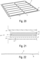
- the methods of the invention comprise a step of providing a larger material comprising said substrate and/or decorative top layer by means of a continuous operation preferably including one or more extrusion operations, scattering operations, pressing operations and/or lamination operations.
- the step of providing a larger material at least comprises one or more extrusion operations and a lamination operation, or at least one or more scattering operations and a lamination operation.
- multiple layers may be laminated, at once, subsequently or in any other sequence.
- the larger material comprises a printed pattern of adjacent rectangular and oblong panels or tiles.
- a printed pattern applied to a carrier layer such as a thermoplastic foil.
- said lower edge areas are at least available in between adjacent longitudinal edges of said panels or tiles.
- the longitudinal edges of said panels or tiles may be directed in the feed direction of said continuous operation.
- the longitudinal edges of said panels are directed transversely to said feed direction. In the latter case the possible stretching of the printed pattern can be controlled in an enhanced manner and the forming operation for said lower edge areas can be executed more accurately, as well as the dividing operation.
- a printed thermoplastic foil for example a printed PVC foil may be used.
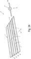
- Figure 1 illustrates some steps in a method for manufacturing a decorative panel 1.
- said panel 1 comprises a substrate 2 and a decorative top layer 3, wherein said substrate is a thermoplastic material containing substrate, wherein said substrate and decorative top layer is obtained from a larger material 4 by means of a dividing operation S1, with as a characteristic that said panel 1 comprises at both upper edges 5 of a pair of opposite side edges a lower edge area 6, wherein said lower edge area 6 is obtained during said dividing operation S1.
- the tongue 10 and groove 9 form part of coupling means with which two of such panels can be coupled at the respective edges, such that they are locked together in a horizontal direction H perpendicular to the respective edge and in the plane of the panels 1, as well as in a vertical direction V perpendicular to the plane of the panels.
- the decorative top layer 3, preferably at least the printed pattern 8 thereof, continues uninterruptedly from on the global upper surface of said panel 1 to and over said lower edge area 6.
- Said lower edge areas 6 at opposite upper edges 5 mutually extend to a same or substantially same depth and/or over a same or substantially a same horizontal distance, as measured perpendicularly to said upper edge 5.
- Said lower edge areas 6 are formed as chamfers, in this case somewhat bent chamfers.
- Said substrate 2 at the location of said lower edge area 6 is compressed or deformed.
- the bottom of the substrate 2 remains undeformed.
- the bottom of the substrate 2 is supported by supporting means 11 to this aim.
- Said substrate 2 and/or decorative top layer 3 show the following properties:
- said lower edge areas 6 are formed simultaneously with, i.e. during said dividing operation S1, such in accordance with the present invention.
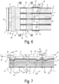
- said dividing operation S1 comprises:
- said mold or mold portions 16 are substantially at standstill during the cutting operation, i.e. while the cutting tool 15 is moved into and through said substrate 2 and decorative layer 3.
- said dividing operation comprises a cutting operation, more particularly a punching operation, namely an operation in which a stationary, i.e. nonrotating, knife is pressed down to, into and through the larger material 4 to be cut.
- the wear layer 18 comprises a relief 19 applied thereto or realized prior to said dividing operation S1.
- Said relief 19 preferably remains available in the lower edge areas 6, after the molding portions 16 are disengaged.
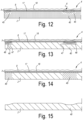
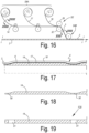
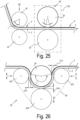
- Figure 16 illustrates a method, not in accordance with the present invention.
- the illustrated method is a further example of said second possibility mentioned in the introduction.
- the lower edge areas 6 are formed prior to said cutting operation S1.
- the printed carrier layer 17, the transparent wear layer 18 and/or the backing layer 14 are laminated to form a decorative top layer 3 in a lamination operation S4A prior to laminating the obtained decorative top layer 3 to said substrate 2 in a subsequent lamination operation S4B.
- a decorative top layer 3 as shown in figure 17 is obtained, namely comprising lower edge areas 6 at the surface thereof having the transparent wear layer 18, while the opposite surface is maintained substantially flat or flat to allow for fluent lamination in said lamination operation S4A.
- this is obtained through a forming operation S2 by means of a structured roller 26 indenting said decorative top layer 3 prior to said lamination operation S4B.
Landscapes
- Engineering & Computer Science (AREA)
- Architecture (AREA)
- Civil Engineering (AREA)
- Structural Engineering (AREA)
- Laminated Bodies (AREA)
Priority Applications (11)
| Application Number | Priority Date | Filing Date | Title |
|---|---|---|---|
| EP21216546.8A EP4088950B1 (en) | 2021-05-12 | 2021-12-21 | Methods for manufacturing a decorative panel |
| PL21216546.8T PL4088950T3 (pl) | 2021-05-12 | 2021-12-21 | Sposoby wytwarzania panelu dekoracyjnego |
| US18/559,177 US20240239132A1 (en) | 2021-05-12 | 2022-05-09 | Methods for manufacturing a decorative panel, and decorative panels |
| PCT/IB2022/054267 WO2022238858A1 (en) | 2021-05-12 | 2022-05-09 | Methods for manufacturing a decorative panel, and decorative panels |
| PL22724261.7T PL4337474T3 (pl) | 2021-05-12 | 2022-05-09 | Sposób wytwarzania panelu dekoracyjnego |
| PT227242617T PT4337474T (pt) | 2021-05-12 | 2022-05-09 | Método para fabricar um painel decorativo |
| MX2023013380A MX2023013380A (es) | 2021-05-12 | 2022-05-09 | Metodos para la fabricacion de un panel decorativo y paneles decorativos. |
| CA3214109A CA3214109A1 (en) | 2021-05-12 | 2022-05-09 | Methods for manufacturing a decorative panel, and decorative panels |
| EP25184029.4A EP4596808A3 (en) | 2021-05-12 | 2022-05-09 | Decorative panel and method for manufacturing thereof |
| ES22724261T ES3048384T3 (en) | 2021-05-12 | 2022-05-09 | Method for manufacturing a decorative panel |
| EP22724261.7A EP4337474B1 (en) | 2021-05-12 | 2022-05-09 | Method for manufacturing a decorative panel |
Applications Claiming Priority (2)
| Application Number | Priority Date | Filing Date | Title |
|---|---|---|---|
| US202163187510P | 2021-05-12 | 2021-05-12 | |
| US202163221596P | 2021-07-14 | 2021-07-14 |
Publications (2)
| Publication Number | Publication Date |
|---|---|
| EP4088949A1 EP4088949A1 (en) | 2022-11-16 |
| EP4088949B1 true EP4088949B1 (en) | 2025-06-25 |
Family
ID=77626907
Family Applications (1)
| Application Number | Title | Priority Date | Filing Date |
|---|---|---|---|
| EP21190114.5A Active EP4088949B1 (en) | 2021-05-12 | 2021-08-06 | Methods for manufacturing a decorative panel |
Country Status (2)
| Country | Link |
|---|---|
| EP (1) | EP4088949B1 (pl) |
| PL (1) | PL4088949T3 (pl) |
Families Citing this family (1)
| Publication number | Priority date | Publication date | Assignee | Title |
|---|---|---|---|---|
| WO2024054149A1 (en) * | 2022-09-07 | 2024-03-14 | Välinge Innovation AB | Method to manufacture a bevel on a building panel and such a building panel |
Family Cites Families (12)
| Publication number | Priority date | Publication date | Assignee | Title |
|---|---|---|---|---|
| IT1183846B (it) * | 1985-05-20 | 1987-10-22 | Mondo Rubber Spa | Rivestimento di materiale sintetico in forma di piastrelle e relativo procedimento di fabbricazione |
| BE1010487A6 (nl) | 1996-06-11 | 1998-10-06 | Unilin Beheer Bv | Vloerbekleding bestaande uit harde vloerpanelen en werkwijze voor het vervaardigen van dergelijke vloerpanelen. |
| PT1676720E (pt) | 2000-06-13 | 2011-02-28 | Flooring Ind Ltd | Revestimento de pavimentos |
| JP4610953B2 (ja) | 2004-07-14 | 2011-01-12 | 株式会社タカラトミー | 絵本型投影玩具 |
| ES2337166T3 (es) | 2004-12-23 | 2010-04-21 | Flooring Industries Ltd. | Panel laminado para suelo. |
| DE102006058655B4 (de) | 2006-12-11 | 2010-01-21 | Ulrich Windmöller Consulting GmbH | Bodenpaneel |
| US8741085B2 (en) * | 2009-08-21 | 2014-06-03 | Awi Licensing Company | Method of making a resilient floor tile |
| BE1019331A5 (nl) | 2010-05-10 | 2012-06-05 | Flooring Ind Ltd Sarl | Vloerpaneel en werkwijzen voor het vervaardigen van vloerpanelen. |
| CN105178555B (zh) | 2010-07-09 | 2018-07-03 | 地板工业有限公司 | 地板镶板 |
| US20120240502A1 (en) * | 2011-03-21 | 2012-09-27 | Steven Wilson | Floating, groutable vinyl floor tile |
| EP2759394A1 (de) | 2013-01-29 | 2014-07-30 | Akzenta Paneele + Profile GmbH | Trägerplatte für Dekorpaneel |
| EP2905135A3 (de) * | 2014-02-05 | 2015-12-02 | Dirk Dammers | Verfahren zur Herstellung eines Paneels |
-
2021
- 2021-08-06 PL PL21190114.5T patent/PL4088949T3/pl unknown
- 2021-08-06 EP EP21190114.5A patent/EP4088949B1/en active Active
Also Published As
| Publication number | Publication date |
|---|---|
| PL4088949T3 (pl) | 2025-09-01 |
| EP4088949A1 (en) | 2022-11-16 |
Similar Documents
| Publication | Publication Date | Title |
|---|---|---|
| EP4337474B1 (en) | Method for manufacturing a decorative panel | |
| EP4088950B1 (en) | Methods for manufacturing a decorative panel | |
| US11396166B2 (en) | Method for manufacturing a plate shaped product and plate shaped product manufactured thereby | |
| EP3808562B1 (en) | Method for manufacturing a floor covering product | |
| US9163414B2 (en) | Floor panel | |
| US12466161B2 (en) | On-line synchronous registering co-extrusion SPC floor and production process therefor | |
| EP4088949B1 (en) | Methods for manufacturing a decorative panel | |
| PL181892B1 (en) | Welding rod for welding together edges of elastic floor covering materials | |
| EA050597B1 (ru) | Способы получения декоративной панели и декоративные панели | |
| CN117337240A (zh) | 用于制造装饰面板的方法和装饰面板 | |
| US20260035936A1 (en) | Decorative panel and method for manufacturing decorative panels | |
| US20240383190A1 (en) | Process for manufacturing a board element comprising cavities | |
| US20240253295A1 (en) | Process for manufacturing a board element comprising cavities | |
| TH2301007337A (th) | วิธีการสำหรับผลิตแผงวัสดุตกแต่งและแผงวัสดุตกแต่ง | |
| WO2025141053A1 (en) | Method for applying a surface structure and panel comprising a surface structure | |
| CN121368532A (zh) | 用于制造装饰镶板的方法以及由此获得的装饰镶板 |
Legal Events
| Date | Code | Title | Description |
|---|---|---|---|
| PUAI | Public reference made under article 153(3) epc to a published international application that has entered the european phase |
Free format text: ORIGINAL CODE: 0009012 |
|
| STAA | Information on the status of an ep patent application or granted ep patent |
Free format text: STATUS: THE APPLICATION HAS BEEN PUBLISHED |
|
| AK | Designated contracting states |
Kind code of ref document: A1 Designated state(s): AL AT BE BG CH CY CZ DE DK EE ES FI FR GB GR HR HU IE IS IT LI LT LU LV MC MK MT NL NO PL PT RO RS SE SI SK SM TR |
|
| STAA | Information on the status of an ep patent application or granted ep patent |
Free format text: STATUS: REQUEST FOR EXAMINATION WAS MADE |
|
| 17P | Request for examination filed |
Effective date: 20230503 |
|
| RBV | Designated contracting states (corrected) |
Designated state(s): AL AT BE BG CH CY CZ DE DK EE ES FI FR GB GR HR HU IE IS IT LI LT LU LV MC MK MT NL NO PL PT RO RS SE SI SK SM TR |
|
| RAP1 | Party data changed (applicant data changed or rights of an application transferred) |
Owner name: UNILIN, BV |
|
| STAA | Information on the status of an ep patent application or granted ep patent |
Free format text: STATUS: EXAMINATION IS IN PROGRESS |
|
| 17Q | First examination report despatched |
Effective date: 20241018 |
|
| GRAP | Despatch of communication of intention to grant a patent |
Free format text: ORIGINAL CODE: EPIDOSNIGR1 |
|
| STAA | Information on the status of an ep patent application or granted ep patent |
Free format text: STATUS: GRANT OF PATENT IS INTENDED |
|
| INTG | Intention to grant announced |
Effective date: 20250319 |
|
| P01 | Opt-out of the competence of the unified patent court (upc) registered |
Free format text: CASE NUMBER: APP_15386/2025 Effective date: 20250328 |
|
| GRAS | Grant fee paid |
Free format text: ORIGINAL CODE: EPIDOSNIGR3 |
|
| GRAA | (expected) grant |
Free format text: ORIGINAL CODE: 0009210 |
|
| STAA | Information on the status of an ep patent application or granted ep patent |
Free format text: STATUS: THE PATENT HAS BEEN GRANTED |
|
| AK | Designated contracting states |
Kind code of ref document: B1 Designated state(s): AL AT BE BG CH CY CZ DE DK EE ES FI FR GB GR HR HU IE IS IT LI LT LU LV MC MK MT NL NO PL PT RO RS SE SI SK SM TR |
|
| REG | Reference to a national code |
Ref country code: GB Ref legal event code: FG4D |
|
| REG | Reference to a national code |
Ref country code: CH Ref legal event code: EP |
|
| REG | Reference to a national code |
Ref country code: DE Ref legal event code: R096 Ref document number: 602021032723 Country of ref document: DE |
|
| REG | Reference to a national code |
Ref country code: CH Ref legal event code: EP |
|
| REG | Reference to a national code |
Ref country code: IE Ref legal event code: FG4D |
|
| PG25 | Lapsed in a contracting state [announced via postgrant information from national office to epo] |
Ref country code: FI Free format text: LAPSE BECAUSE OF FAILURE TO SUBMIT A TRANSLATION OF THE DESCRIPTION OR TO PAY THE FEE WITHIN THE PRESCRIBED TIME-LIMIT Effective date: 20250625 |
|
| PGFP | Annual fee paid to national office [announced via postgrant information from national office to epo] |
Ref country code: DE Payment date: 20250827 Year of fee payment: 5 |
|
| REG | Reference to a national code |
Ref country code: LT Ref legal event code: MG9D |
|
| PG25 | Lapsed in a contracting state [announced via postgrant information from national office to epo] |
Ref country code: NO Free format text: LAPSE BECAUSE OF FAILURE TO SUBMIT A TRANSLATION OF THE DESCRIPTION OR TO PAY THE FEE WITHIN THE PRESCRIBED TIME-LIMIT Effective date: 20250925 Ref country code: GR Free format text: LAPSE BECAUSE OF FAILURE TO SUBMIT A TRANSLATION OF THE DESCRIPTION OR TO PAY THE FEE WITHIN THE PRESCRIBED TIME-LIMIT Effective date: 20250926 |
|
| PGFP | Annual fee paid to national office [announced via postgrant information from national office to epo] |
Ref country code: TR Payment date: 20250803 Year of fee payment: 5 Ref country code: PL Payment date: 20250721 Year of fee payment: 5 |
|
| PG25 | Lapsed in a contracting state [announced via postgrant information from national office to epo] |
Ref country code: BG Free format text: LAPSE BECAUSE OF FAILURE TO SUBMIT A TRANSLATION OF THE DESCRIPTION OR TO PAY THE FEE WITHIN THE PRESCRIBED TIME-LIMIT Effective date: 20250625 |
|
| PG25 | Lapsed in a contracting state [announced via postgrant information from national office to epo] |
Ref country code: HR Free format text: LAPSE BECAUSE OF FAILURE TO SUBMIT A TRANSLATION OF THE DESCRIPTION OR TO PAY THE FEE WITHIN THE PRESCRIBED TIME-LIMIT Effective date: 20250625 |
|
| PGFP | Annual fee paid to national office [announced via postgrant information from national office to epo] |
Ref country code: AT Payment date: 20251020 Year of fee payment: 5 Ref country code: FR Payment date: 20250825 Year of fee payment: 5 |
|
| PG25 | Lapsed in a contracting state [announced via postgrant information from national office to epo] |
Ref country code: RS Free format text: LAPSE BECAUSE OF FAILURE TO SUBMIT A TRANSLATION OF THE DESCRIPTION OR TO PAY THE FEE WITHIN THE PRESCRIBED TIME-LIMIT Effective date: 20250925 |
|
| PG25 | Lapsed in a contracting state [announced via postgrant information from national office to epo] |
Ref country code: LV Free format text: LAPSE BECAUSE OF FAILURE TO SUBMIT A TRANSLATION OF THE DESCRIPTION OR TO PAY THE FEE WITHIN THE PRESCRIBED TIME-LIMIT Effective date: 20250625 |
|
| REG | Reference to a national code |
Ref country code: NL Ref legal event code: MP Effective date: 20250625 |
|
| PG25 | Lapsed in a contracting state [announced via postgrant information from national office to epo] |
Ref country code: NL Free format text: LAPSE BECAUSE OF FAILURE TO SUBMIT A TRANSLATION OF THE DESCRIPTION OR TO PAY THE FEE WITHIN THE PRESCRIBED TIME-LIMIT Effective date: 20250625 |
|
| PG25 | Lapsed in a contracting state [announced via postgrant information from national office to epo] |
Ref country code: PT Free format text: LAPSE BECAUSE OF FAILURE TO SUBMIT A TRANSLATION OF THE DESCRIPTION OR TO PAY THE FEE WITHIN THE PRESCRIBED TIME-LIMIT Effective date: 20251027 |
|
| REG | Reference to a national code |
Ref country code: AT Ref legal event code: MK05 Ref document number: 1806108 Country of ref document: AT Kind code of ref document: T Effective date: 20250625 |
|
| PG25 | Lapsed in a contracting state [announced via postgrant information from national office to epo] |
Ref country code: IS Free format text: LAPSE BECAUSE OF FAILURE TO SUBMIT A TRANSLATION OF THE DESCRIPTION OR TO PAY THE FEE WITHIN THE PRESCRIBED TIME-LIMIT Effective date: 20251025 |
|
| PG25 | Lapsed in a contracting state [announced via postgrant information from national office to epo] |
Ref country code: AT Free format text: LAPSE BECAUSE OF FAILURE TO SUBMIT A TRANSLATION OF THE DESCRIPTION OR TO PAY THE FEE WITHIN THE PRESCRIBED TIME-LIMIT Effective date: 20250625 Ref country code: SM Free format text: LAPSE BECAUSE OF FAILURE TO SUBMIT A TRANSLATION OF THE DESCRIPTION OR TO PAY THE FEE WITHIN THE PRESCRIBED TIME-LIMIT Effective date: 20250625 |
|
| PG25 | Lapsed in a contracting state [announced via postgrant information from national office to epo] |
Ref country code: CZ Free format text: LAPSE BECAUSE OF FAILURE TO SUBMIT A TRANSLATION OF THE DESCRIPTION OR TO PAY THE FEE WITHIN THE PRESCRIBED TIME-LIMIT Effective date: 20250625 |
|
| PG25 | Lapsed in a contracting state [announced via postgrant information from national office to epo] |
Ref country code: EE Free format text: LAPSE BECAUSE OF FAILURE TO SUBMIT A TRANSLATION OF THE DESCRIPTION OR TO PAY THE FEE WITHIN THE PRESCRIBED TIME-LIMIT Effective date: 20250625 |
|
| PG25 | Lapsed in a contracting state [announced via postgrant information from national office to epo] |
Ref country code: SK Free format text: LAPSE BECAUSE OF FAILURE TO SUBMIT A TRANSLATION OF THE DESCRIPTION OR TO PAY THE FEE WITHIN THE PRESCRIBED TIME-LIMIT Effective date: 20250625 |
|
| PG25 | Lapsed in a contracting state [announced via postgrant information from national office to epo] |
Ref country code: ES Free format text: LAPSE BECAUSE OF FAILURE TO SUBMIT A TRANSLATION OF THE DESCRIPTION OR TO PAY THE FEE WITHIN THE PRESCRIBED TIME-LIMIT Effective date: 20250625 |
|
| PG25 | Lapsed in a contracting state [announced via postgrant information from national office to epo] |
Ref country code: RO Free format text: LAPSE BECAUSE OF FAILURE TO SUBMIT A TRANSLATION OF THE DESCRIPTION OR TO PAY THE FEE WITHIN THE PRESCRIBED TIME-LIMIT Effective date: 20250625 |
|
| REG | Reference to a national code |
Ref country code: CH Ref legal event code: H13 Free format text: ST27 STATUS EVENT CODE: U-0-0-H10-H13 (AS PROVIDED BY THE NATIONAL OFFICE) Effective date: 20260324 |
|
| PG25 | Lapsed in a contracting state [announced via postgrant information from national office to epo] |
Ref country code: MC Free format text: LAPSE BECAUSE OF FAILURE TO SUBMIT A TRANSLATION OF THE DESCRIPTION OR TO PAY THE FEE WITHIN THE PRESCRIBED TIME-LIMIT Effective date: 20250625 |
|
| PG25 | Lapsed in a contracting state [announced via postgrant information from national office to epo] |
Ref country code: DK Free format text: LAPSE BECAUSE OF FAILURE TO SUBMIT A TRANSLATION OF THE DESCRIPTION OR TO PAY THE FEE WITHIN THE PRESCRIBED TIME-LIMIT Effective date: 20250625 |
|
| PG25 | Lapsed in a contracting state [announced via postgrant information from national office to epo] |
Ref country code: LU Free format text: LAPSE BECAUSE OF NON-PAYMENT OF DUE FEES Effective date: 20250806 Ref country code: IT Free format text: LAPSE BECAUSE OF FAILURE TO SUBMIT A TRANSLATION OF THE DESCRIPTION OR TO PAY THE FEE WITHIN THE PRESCRIBED TIME-LIMIT Effective date: 20250625 |