EP4088940A1 - Medium holding device - Google Patents
Medium holding device Download PDFInfo
- Publication number
- EP4088940A1 EP4088940A1 EP20912051.8A EP20912051A EP4088940A1 EP 4088940 A1 EP4088940 A1 EP 4088940A1 EP 20912051 A EP20912051 A EP 20912051A EP 4088940 A1 EP4088940 A1 EP 4088940A1
- Authority
- EP
- European Patent Office
- Prior art keywords
- suction force
- medium
- suction
- output level
- blower
- Prior art date
- Legal status (The legal status is an assumption and is not a legal conclusion. Google has not performed a legal analysis and makes no representation as to the accuracy of the status listed.)
- Withdrawn
Links
Images



Classifications
-
- B—PERFORMING OPERATIONS; TRANSPORTING
- B41—PRINTING; LINING MACHINES; TYPEWRITERS; STAMPS
- B41J—TYPEWRITERS; SELECTIVE PRINTING MECHANISMS, i.e. MECHANISMS PRINTING OTHERWISE THAN FROM A FORME; CORRECTION OF TYPOGRAPHICAL ERRORS
- B41J11/00—Devices or arrangements of selective printing mechanisms, e.g. ink-jet printers or thermal printers, for supporting or handling copy material in sheet or web form
- B41J11/0085—Using suction for maintaining printing material flat
-
- B—PERFORMING OPERATIONS; TRANSPORTING
- B41—PRINTING; LINING MACHINES; TYPEWRITERS; STAMPS
- B41J—TYPEWRITERS; SELECTIVE PRINTING MECHANISMS, i.e. MECHANISMS PRINTING OTHERWISE THAN FROM A FORME; CORRECTION OF TYPOGRAPHICAL ERRORS
- B41J11/00—Devices or arrangements of selective printing mechanisms, e.g. ink-jet printers or thermal printers, for supporting or handling copy material in sheet or web form
- B41J11/02—Platens
-
- B—PERFORMING OPERATIONS; TRANSPORTING
- B41—PRINTING; LINING MACHINES; TYPEWRITERS; STAMPS
- B41J—TYPEWRITERS; SELECTIVE PRINTING MECHANISMS, i.e. MECHANISMS PRINTING OTHERWISE THAN FROM A FORME; CORRECTION OF TYPOGRAPHICAL ERRORS
- B41J2/00—Typewriters or selective printing mechanisms characterised by the printing or marking process for which they are designed
- B41J2/005—Typewriters or selective printing mechanisms characterised by the printing or marking process for which they are designed characterised by bringing liquid or particles selectively into contact with a printing material
- B41J2/01—Ink jet
-
- B—PERFORMING OPERATIONS; TRANSPORTING
- B41—PRINTING; LINING MACHINES; TYPEWRITERS; STAMPS
- B41J—TYPEWRITERS; SELECTIVE PRINTING MECHANISMS, i.e. MECHANISMS PRINTING OTHERWISE THAN FROM A FORME; CORRECTION OF TYPOGRAPHICAL ERRORS
- B41J3/00—Typewriters or selective printing or marking mechanisms characterised by the purpose for which they are constructed
- B41J3/28—Typewriters or selective printing or marking mechanisms characterised by the purpose for which they are constructed for printing downwardly on flat surfaces, e.g. of books, drawings, boxes, envelopes, e.g. flat-bed ink-jet printers
Definitions
- the present invention relates to a medium holding device.
- an adsorption unit using a fan is provided on a suction table (printing table) on which a medium is placed.
- Patent Literature 1 Japanese Unexamined Patent Publication No. 2007-175948
- the medium is fixed to the upper surface of the suction table by the adsorption force (suction force) generated by the adsorption unit (suction force generating unit) at the time of printing on the medium.
- the suction force generated by the suction force generating unit is changed according to the thickness of the medium to print.
- the suction force is changed by changing the rotation speed of the fan.
- the suction force is generated by rotating a fan at a constant speed determined according to a required suction force.
- the suction force generated by the suction force generating unit is affected not only by the thickness of the medium but also by the area, temperature, humidity, and the like of the medium.
- a first invention relates to a medium holding device including:
- the suction force can be optimized while maintaining the suction force with which the medium can be held on the table.
- the suction force can be adjusted at an appropriate timing while maintaining the suction force with which the medium can be held on the table.
- the suction force can be adjusted at an appropriate timing while maintaining the suction force with which the medium can be held on the table.
- the suction force can be adjusted at an appropriate timing while maintaining the suction force with which the medium can be held on the table.
- the suction force is weakened in a step-wise manner while maintaining the suction force with which the medium can be held on the table.
- occurrence of a situation where the suction force becomes too weak while the suction force is being weakened and the medium cannot be appropriately held on the table can be suitably prevented.
- control unit is configured not to weaken the suction force even if the confirmed actual suction force is confirmed to be within the first threshold value range when the confirmed actual suction force has reached a lower limit suction force.
- the suction force when the suction force is weaker than the lower limit suction force, it may become difficult to hold the medium on the table. Therefore, when weakening the suction force in a step-wise manner, the suction force is weakened with the lower limit suction force as the limit, so that the occurrence of a situation where the suction force becomes weaker than the lower limit suction force and the medium cannot be appropriately held on the suction table can be suitably prevented.
- control unit is configured to strengthen the suction force when the confirmed actual suction force is confirmed to be outside a second threshold value range in which the first threshold value range is enlarged toward a side the suction force becomes weaker.
- the weakened suction force when the suction force generated on the suction table is weakened, the weakened suction force can be quickly returned to the original suction force.
- control unit is configured to, after weakening the suction force, maintain the suction force without changing while the confirmed actual suction force is within the second threshold value range and outside the first threshold value range.
- the medium can be appropriately held by maintaining the suction force without changing while the support of the medium is not impaired even if the suction force is weakened.
- the suction force can be optimized.
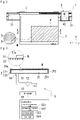
- Fig. 1 is a perspective view of an inkjet printing apparatus 1.
- Fig. 2 is a plan view of the inkjet printing apparatus 1 as viewed from above.
- Fig. 3 is a diagram schematically illustrating a connection relationship between a suction table 2 and a suction force generating mechanism 5.
- a portion involved in generation of suction force in the suction table 2 is schematically illustrated in a cross section, which cross section corresponds to a cross section taken along line A-A in Fig. 2 .
- a vertical direction based on an installation state of the inkjet printing apparatus 1 is the Z direction.
- a main scanning direction of a carriage 4 (inkjet head 41) is the Y direction.
- a sub scanning direction of the carriage 4 (inkjet head 41) is the X direction.
- the inkjet printing apparatus 1 has a suction table 2 (table) on which a medium M, which is a printing target object, is placed.
- a guide rail 3 (Y bar) disposed in an orientation along the Y direction is provided above the suction table 2.
- One end and the other end in the longitudinal direction of the guide rail 3 are supported by support members 31 and 32 disposed on both sides in the width direction (Y direction) of the suction table 2.
- the support members 31 and 32 are provided to be movable in the longitudinal direction (X direction) of the suction table 2 by a drive mechanism (not illustrated).
- the guide rail 3 supported by the support members 31 and 32 is also moved in the longitudinal direction (X direction) of the suction table 2.
- the guide rail 3 is provided in an orientation crossing the suction table 2 in the width direction (Y direction) and is provided horizontally above the suction table 2.
- the guide rail 3 supports the carriage 4 that holds the inkjet head 41 (see hidden lines in Fig. 2 ).
- the carriage 4 is provided to be movable forward and backward in the longitudinal direction (Y direction) of the guide rail 3.
- the support members 31, 32 are moved in the sub scanning direction (X direction) by a drive mechanism (not shown), and the carriage 4 is moved in the main scanning direction (Y direction) by a drive mechanism (not shown).
- ink droplets are ejected from the inkjet head 41 located above the medium M toward the upper surface of the medium M, and information such as characters and images is printed on the medium M.
- the ink droplets ejected onto the medium M are solidified by the ultraviolet light irradiated from a UV irradiation device 42 on both sides of the inkjet head 41, and are fixed on the medium M.
- the UV irradiation devices 42 are located on both sides of the inkjet head 41 in the Y direction.
- the suction table 2 of the inkjet printing apparatus 1 includes a table base 20 having an opening 20a on the upper surface, and a table top 21 internally fitted into the opening 20a of the table base 20.
- the table base 20 includes a bottom wall portion 201 and a peripheral wall portion 202 surrounding the outer periphery of the bottom wall portion 201.
- the table base 20 has a rectangular shape in plan view as viewed from the upper side in the vertical direction (Z direction).
- the opening 20a of the table base 20 has a rectangular shape in plan view of the suction table 2 as viewed from above.
- the table top 21 also has a rectangular shape in plan view. When the table top 21 is internally fitted into the opening 20a, an internal space 23 is formed between the table base 20 and the table top 21.
- the upper surface of the table top 21 serves as a placement surface 21a for the medium M, and the placement surface 21a is provided with a plurality of suction holes 22 (through holes) over substantially the entire surface.
- the internal space 23 of the suction table 2 communicates with the outside via the suction holes 22 provided in the table top 21.
- a piping 51 of the suction force generating mechanism 5 is connected to the table base 20 of the suction table 2.
- the piping 51 is communicated to the internal space 23 of the suction table 2.
- the piping 51 is provided with a blower 52 of the suction force generating mechanism 5.
- the blower 52 is driven by an inverter 53 controlled by the controller 55.
- the output level of the blower 52 changes according to the output level of the inverter 53.
- the blower 52 operates at the maximum output level, and the blown air volume of the blower 52 becomes a maximum.
- the output level of the blower 52 increases or decreases in conjunction with the increase or decrease of the output level of the inverter 53.
- the blower 52 forms a flow of air from one side to the other side of the blower 52 by rotation of an impeller (not illustrated).
- the operation/stop of the blower 52 is controlled by the controller 55.
- the blower 52 forms a flow of air from the internal space 23 of the suction table 2 toward the blower 52 in the piping 51, and generates a pressure state (negative pressure state) lower than the atmospheric pressure in the internal space 23.
- a pressure sensor 54 is provided in the vicinity of a communication opening with the internal space 23. An output signal of the pressure sensor 54 is input to the controller 55.
- the controller 55 includes a pressure calculation unit 551, a suction force control unit 552, a switching unit 553, and a counter 554 as functional blocks.
- the pressure calculation unit 551 calculates a pressure value Pin inside the internal space 23 from the output signal of the pressure sensor 54.
- the pressure value Pin of the internal space 23 is handled as an index indicating the suction force generated on the placement surface 21a of the suction table 2.
- the magnitude of the calculated pressure value Pin inside the internal space 23 means the magnitude of the suction force generated in the suction table 2.
- the suction force control unit 552 controls the output level of the inverter 53 to control the operation/stop of the blower 52 and the blown air volume of the blower 52.
- the switching unit 553 switches the output level of the inverter 53 to change the suction force generated in the suction table 2. Specifically, the output level of the inverter 53 is switched based on the pressure value Pin of the internal space 23 calculated by the pressure calculation unit 551.
- the counter 554 counts an elapsed time from the start of operation of the blower 52.
- the blower 52 is not particularly limited as long as a flow of air can be formed in the piping 51.
- a fan having a compression ratio of less than or equal to 1.1, a blower having a compression ratio of about 1.1 to 2.0, or the like can be appropriately selected.
- the medium M placed on the suction table 2 is suctioned to the placement surface 21a of the suction table 2 by the suction force generated by the operation of the blower 52, and is held in a state where the movement in the horizontal direction (X direction, Y direction) is restricted.
- information such as an image or a character is printed on the medium M whose movement in the horizontal direction is restricted.
- the size of the suction table 2 is set according to the medium having the largest size to be printed by the inkjet printing apparatus 1.
- the negative pressure generated in the internal space 23 is reduced by the air flowing into the internal space 23 from the region of the suction hole 22 not covered with the medium M.
- the suction force generated in the region of the suction hole 22 covered with the medium M is weakened, and the holding of the medium M on the placement surface 21a may be affected.
- the pressure value Pin of the internal space 23 is regarded as an index of the suction force generated by the suction table 2, and is used for the control of the blower 52 by the controller 55.
- the controller 55 optimizes the blown air volume of the blower 52 by adjusting the blown air volume of the blower 52 within a range not impairing the negative pressure (suction force) of the internal space 23.
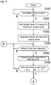
- Figs. 4 and 5 are flowcharts of suction force adjusting process performed by the controller 55.
- the pressure value Pin of the internal space 23 measured by the pressure sensor 54 is used as an index of the suction force generated on the suction table 2.
- the target value of the pressure in the internal space 23 is set when carrying out printing on the medium M.
- a target pressure value Pt is a target value of the pressure of the internal space 23 that generates the target suction force (first suction force) on the suction table 2.
- the target pressure value Pt may be manually and arbitrarily set by the user, or may be uniformly set to a predetermined value determined according to the size of the medium M.
- Step S101 When the target pressure value Pt is set (Step S101, Yes), the controller 55 (suction force control unit 552) sets the output level of the inverter 53 to the maximum output level (step S102).
- the output level of the inverter 53 is not necessarily set to the maximum output level, and may be any output level as long as the pressure of the internal space 23 can be reduced toward the target pressure value Pt.
- the target pressure value Pt is set within this range.
- the output level of the inverter 53 is divided into 21 stages from “0" to "20” by way of an example. For example, when the output level is set to "20", the blown air volume of the blower 52 is maximized, and when the output level is set to "0", the blowing by the blower 52 is stopped.
- the output level of the inverter 53 increases, the output level of the blower 52 also increases, and the air quantity drawn from the internal space 23 toward the blower 52 increases, so that the pressure value Pin of the internal space 23 of the suction table 2 can be reduced. That is, the suction force to generate can be strengthened.
- the controller 55 operates the blower 52 by controlling the inverter 53 at the set output level (step S103).
- step S104 When elapse of a preset weight time (e.g., one second) is confirmed by the counter 554 (step S104, Yes), the controller 55 (pressure calculation unit 551) acquires the pressure value Pin (suction force at current time point) of the internal space 23 from the output value of the pressure sensor 54 (step S105).
- a preset weight time e.g., one second
- the controller 55 (switching unit 553) confirms whether or not the pressure value Pin of the internal space 23 has reached within a first threshold value range and the decompression of the internal space 23 has been completed (step S106).
- Pin is the pressure value of the internal space 23 at the current time point
- Pt is the target pressure value of the internal space set in step S101.
- the first threshold value range is a predetermined range on the side where the suction force based on the target pressure value Pt is weak (the pressure value Pin is low).
- the range of -4 kPa ⁇ Pin ⁇ -5 kPa is set as the first threshold value range.
- step S106 is negative, and the processes from steps S 104 to S106 are repeated.
- step S106 determines whether the pressure value Pin of the internal space 23 reduced toward the target pressure value Pt falls within the first threshold value range. If the pressure value Pin of the internal space 23 reduced toward the target pressure value Pt falls within the first threshold value range (step S106, Yes), determination is made that the decompression of the internal space 23 is completed, and the process proceeds to step S107 (see Fig. 5 ).
- step S107 is the process for adjusting the output level of the inverter 53 to optimize the operation of the blower 52.
- step S107 the controller 55 (switching unit 553) confirms whether or not the output level of the inverter 53 is higher than the lower limit output level.
- the lower limit output level of the inverter 53 is the output level "2".
- the blown air volume of the blower 52 is the minimum air quantity at which the inside of the internal space 23 can be maintained in a negative pressure state.
- the negative pressure state of the internal space 23 when the output level is "2" means the minimum pressure that can regulate the movement of the medium M on the suction table 2 and hold the medium M on the suction table 2.
- the suction force generated on the suction table 2 at the minimum pressure that can hold the medium M on the suction table 2 corresponds to the lower limit suction force.
- step S107 After the process of step S106, the output level of the inverter 53 remains at the maximum output level set in step S102. Therefore, the determination in step S107 is positive (step S107, Yes), and the process proceeds to step S108.
- Step S107 is provided to confirm whether the output level has reached the lower limit when the output level of the inverter 53 is reduced by the process to be described later.
- step S108 the controller 55 (switching unit 553) lowers the output level of the inverter 53 by one stage. As a result, when the output level of the inverter 53 is "20", the output level of the inverter 53 is changed to "19".
- step S110, Yes When elapse of a preset weight time (e.g., one second) is confirmed by the counter 554 (step S110, Yes), the controller 55 (pressure calculation unit 551) acquires the pressure value Pin of the internal space 23 from the output value of the pressure sensor 54 (step S111).
- a preset weight time e.g., one second
- the controller 55 (switching unit 553) confirms whether or not the pressure value Pin of the internal space 23 is remained within a second threshold value range and the decompression level of the internal space 23 is within an allowable range (step S112).
- Pin is the pressure value of the internal space 23 at the current time point
- Pt is the target pressure value set in step S101.
- step S112 when the pressure value Pin of the internal space 23 is within the range of -2 kPa ⁇ Pin ⁇ -5 kPa, the condition of the above formula (2) is satisfied and determination is made that the decompression level of the internal space 23 is within the allowable range (step S112, Yes).
- the second threshold value range is a predetermined range in which the first threshold value range is enlarged toward the side the pressure value reduces (the suction force reduces) with the target pressure value Pt as a reference. For example, when the target pressure value Pt is -5 kPa, the range of -2 kPa ⁇ Pin ⁇ -5 kPa is set as the second threshold value range.
- step S112 When the pressure value Pin of the internal space 23 is within the second threshold value range (step S112, Yes), the influence on the decompression level of the internal space 23 by the reduction of the blown air volume of the blower 52 is within the allowable range that does not affect the holding of the medium M.
- step S113 the controller 55 (switching unit 553) confirms whether or not the pressure value Pin of the internal space 23 is within the first threshold value range and the output level of the inverter 53 can be further reduced (step S113).
- Pin is the pressure value of the internal space 23 at the current time point
- Pt is the target pressure value set in step S101.
- the blown air volume of the blower 52 reduces, and the pressure value Pin of the internal space 23 of the suction table 2 may possibly reduce in a direction away from the target pressure value Pt (direction in which the suction force weakens).
- step S113 determination is made that the output level of the inverter 53 can be further reduced (step S113, Yes), and the process proceeds to step S107.
- step S108 to be newly performed the output level of the inverter 53 is further lowered by one stage.
- the output level of the inverter 53 is changed from “19" to "18".
- step S112 When the pressure value Pin of the internal space 23 is within the second threshold value range (step S112, Yes) but outside the first threshold value range (step S113, No), the reduction in the blown air volume of the blower 52 is within the allowable range that does not affect the holding of the medium M, but the output level of the inverter 53 cannot be further lowered by one stage.
- step S110 to step S113 are repeated, and the output level of the inverter 53 remains maintained.
- step S113 When the pressure value Pin of the internal space 23 reaches within the first threshold value range (step S113, Yes) while the processes from step S110 to step S113 are repeated, the process proceeds to step S107.
- step S107 to step S113 the processes from step S107 to step S113 are repeated, and the output level of the inverter 53 is reduced in a step-wise manner one stage at a time.
- step S107, No when the output level of the inverter 53 reaches the lower limit output level (step S107, No), the output level of the inverter 53 is thereafter maintained at the lower limit output level (step S109).
- the blown air volume of the blower 52 is held at a blown air volume at which the pressure value Pin of the internal space 23 can maintain the internal space 23 in the negative pressure state.
- step S112 when the pressure value Pin of the internal space 23 deviates from the second threshold value range (step S112, No) after the output level of the inverter 53 is lowered by one stage, the controller 55 (switching unit 553) confirms whether or not the output level of the inverter 53 at the current time point is less than the maximum output level (step S114).
- step S114 when the output level of the inverter 53 at the current time point is less than the maximum output level (step S114, Yes), the controller 55 (switching unit 553) increases the output level of the inverter 53 by one stage (step S115).
- the controller 55 (switching unit 553) confirms whether or not the pressure value Pin of the internal space 23 after the output level of the inverter 53 is increased by one stage is within the second threshold value range (step S112).
- step S112, No When the pressure value Pin of the internal space 23 is outside the second threshold value range (step S112, No) even after the output level of the inverter 53 is increased by one stage, steps S110, S111, S112, S114, and S115 are repeated.
- step S112, S114, and S115 the output level of the inverter 53 is raised by one stage (steps S112, S114, and S115).
- step S114 when the output level of the inverter 53 is raised to the maximum output level (step S114, No), the output level cannot be raised any more, and thus the process proceeds to step S104 described above (see Fig. 4 ).
- steps S110, S111, S112, and S113 are repeated until the pressure value Pin of the internal space 23 reaches within the first threshold value range (step S113, No).
- the output level of the inverter 53 is held without being changed.
- step S113 When the pressure value Pin of the internal space 23 falls within the first threshold value range (step S113, Yes) while steps S110, S111, S112 and S113 are being repeated, the process proceeds to step S107.
- step S107 to step S113 the processes from step S107 to step S113 are repeated, and the output level of the inverter 53 is reduced in a step-wise manner one stage at a time.
- the controller 55 (switching unit 553) optimizes the air blown air volume of the blower 52 by increasing or decreasing the output level of the inverter 53 while holding the pressure value Pin of the internal space 23 within at least the second threshold value range.
- the controller 55 lowers the output level of the blower 52 in a step-wise manner while maintaining the suction force.
- the controller 55 switching unit 553 lowers the output level of the blower 52 in a step-wise manner while maintaining the suction force.
- the second suction force in the invention is a suction force weaker than the first suction force, and is a suction force between the first suction force and the lower limit suction force (first suction force > second suction force ⁇ lower limit suction force).
- the second suction force changes according to the type and size of the medium M placed on the suction table 2, the machine body difference of the inkjet printing apparatus 1 and the blower 52, the usage environment, and the like.
- the controller 55 switches from the first suction force to the second suction force based on the pressure value Pin of the internal space 23.
- the timing of switching from the first suction force to the second suction force may be as follows.
- the inkjet printing apparatus 1 has the following configuration.
- the controller 55 includes a switching unit 553 that switches the suction force to be generated.
- the switching unit 553 drives the blower 52 at the first output level to generate the first suction force, and suctions the medium M placed on the placement surface 21a. Thereafter, the blower 52 is driven at the second output level lower than the first output level to generate the second suction force weaker than the first suction force, thereby suctioning the medium M placed on the placement surface 21a.
- the suction force can be optimized while maintaining the suction force with which the medium M can be held on the suction table 2.
- the inkjet printing apparatus 1 has the following configuration.
- the controller 55 switches from the first suction force to the second suction force according to (a) the suction time of the medium M with the first suction force, (b) the actual suction force (pressure value Pin of the internal space 23 of the suction table 2) realized by the suction of the medium M with the first suction force, or (c) the processing mode of the processing unit (operation mode of the inkjet printing apparatus 1) that processes the medium M placed on the placement surface 21a.
- the suction force can be optimized at an appropriate timing while maintaining the suction force with which the medium M can be held on the suction table 2.
- the inkjet printing apparatus 1 has the following configuration.
- the controller 55 includes:
- the suction force can be optimized at an appropriate timing while maintaining the suction force with which the medium M can be held on the suction table 2.
- the inkjet printing apparatus 1 has the following configuration.
- the controller 55 includes a counter 554.
- the switching unit 553 switches the suction force to the second suction force when the elapsed time from the start of suction of the medium M with the first suction force reaches a specified time defined in advance by the counter 554.
- the specified time is a time from the start of suction of the medium M with the first suction force until the change amount of the actual suction force realized by the suction of the medium M with the first suction force converges.
- the suction force can be optimized at an appropriate timing while maintaining the suction force with which the medium M can be held on the suction table 2.
- the inkjet printing apparatus 1 has the following configuration.
- the controller 55 reduces, in a step-wise manner, the output level of the blower 52 when switching the suction force from the first suction force to the second suction force, to weaken the suction force in a step-wise manner.
- the controller 55 switching unit 553:
- the output level of the blower 52 can be lowered in a step-wise manner while maintaining the suction force with which the medium M can be held on the suction table 2.
- occurrence of a situation where the suction force becomes too weak while the output level of the blower 52 is being lowered and the medium M cannot be appropriately held on the suction table 2 can be suitably prevented.
- the inkjet printing apparatus 1 has the following configuration.
- the controller 55 confirms the pressure value Pin (actual suction force) of the internal space 23, which is an index of the suction force, and when the confirmed actual suction force has reached the lower limit suction force, does not change the output level of the blower 52 even if it is confirmed that the confirmed pressure value Pin is within the first threshold value range.
- the output level of the blower 52 When the output level of the blower 52 is lowered below the lower limit output level, it may become difficult to maintain the suction force. Therefore, with the above configuration, the output level can be reduced with the lower limit suction force as the limit when the output level of the blower 52 is reduced in a step-wise manner. Thus, occurrence of a situation where the suction force becomes weaker than the lower limit suction force and the medium M cannot be appropriately held on the suction table 2 can be suitably prevented.
- the inkjet printing apparatus 1 has the following configuration.
- the controller 55 increases the output level of the blower 52 to strengthen the suction force when confirmed that the confirmed pressure value Pin is outside the second threshold value range in which the first threshold value range is enlarged toward the side the suction force becomes weak.
- the weakened suction force can be quickly returned to the original suction force.
- the inkjet printing apparatus 1 has the following configuration.
- the controller 55 (switching unit 553) maintains the output level of the blower 52 without changing while the confirmed pressure value Pin is within the second threshold value range and outside the first threshold value range to maintain the suction force without changing.
- the medium M can be appropriately held by maintaining the output level of the blower 52 without changing while the support of the medium M is not impaired even if the suction force is weakened.
- the inkjet printing apparatus 1 has the following configuration.
- the controller 55 lowers the output level of the blower 52 to a minimum output level at which the pressure value Pin can be held within the first threshold value range up until the printing operation on the medium M placed on the placement surface 21a is started.
- the printing operation on the medium M can be performed while reliably holding the medium M on the placement surface 21a. If the holding of the medium M is insufficient, wrinkles and floating may occur on the surface of the medium M, in which case, printing at a portion where wrinkles and floating occurred may be hindered, but the occurrence of such a situation can be suitably prevented.
- Adjustment of the output level of the blower 52 is not limited only to this aspect.
- the output level of the blower 52 may be reduced to the minimum output level at which the pressure value Pin in the internal space 23 can be held within the first threshold value range after the change rate per unit time of the pressure value Pin becomes less than the change rate of the threshold value.
- Fig. 6 is a flowchart of suction force adjusting process according to a modified example.
- Fig. 7(a) is a time chart for explaining a change in the pressure value Pin (suction force) in the internal space 23 when the suction force adjusting process according to the modified example is performed.
- Fig. 7(b) is a time chart for explaining a change in the air quantity of the blower 52 when the suction force adjusting process according to the modified example is performed.
- the controller 55 determines the initial output level of the output level of the inverter 53 (step S202).
- the initial output level is a fixed value determined according to the target pressure value Pt, the size of the medium M, and the like. It is a value determined through experiments and simulations.
- the initial output level may be set as the maximum output level.
- the controller 55 operates the blower 52 by controlling the inverter 53 at the set output level (step S203).
- the controller 55 acquires the pressure value Pin (suction force at current time point) of the internal space 23 from the output value of the pressure sensor 54 (step S205).
- the controller 55 confirms the presence or absence of data (past data) of the pressure value Pin of the internal space 23 that has already been measured (step S206).
- step S206 Since there is no past data immediately after the operation of the stopped blower 52 (step S206, No), the process proceeds to step S204 in such a case.
- the controller 55 calculates a change rate ⁇ P/min per unit time ⁇ t from a difference between the pressure value Pin (PI) of the internal space 23 measured the previous time and the pressure value Pin (P2) of the internal space 23 measured this time (step S207).
- step S208 whether or not the calculated change rate ⁇ P/min is smaller than a third threshold value Th3 is confirmed.
- the pressure value Pin of the internal space 23 reduces from the atmospheric pressure toward the target pressure value Pt (see Fig. 7(a) ).
- the change rate ⁇ P/min of the pressure value Pin is large immediately after the start of the operation of the blower 52 (time t0), when the elapsed time from the start of the operation becomes long, the change rate ⁇ P/min becomes small, and the pressure value Pin becomes difficult to decrease.
- the suction force on the suction table 2 stabilizes as a result of the change rate ⁇ P/min of the pressure value Pin in the internal space 23 converging and the pressure value stabilizing.
- step S208, Yes determination is made that the decompression of the internal space 23 is completed (step S208, Yes) at a time point the change rate ⁇ P/min of the pressure value Pin in the internal space 23 becomes less than the third threshold value Th3.
- step S209, No the controller 55 (switching unit 553) changes the output level of the inverter 53 to the adjusted output level.
- the adjusted output level is the output level at which the blown air volume of the blower 52 can be suppressed while maintaining the pressure value Pin of the internal space 23 within the pressure range that can regulate the movement of the medium M.
- the adjusted output level is a value determined in advance through experiments and simulations.
- the air blown air volume of the blower 52 increases to the blown air volume determined according to the initial output level and then is maintained at a constant blown air volume, as indicated by a solid line a in the figure.
- the blown air volume of the blower 52 is decreased to the blown air volume determined according to the adjusted output level, and then is maintained at the decreased blown air volume, as indicated by a solid line b in the figure.
- the blown air volume determined according to the adjusted output level is a blown air volume that can hold the pressure value Pin of the internal space 23 within a pressure range that can regulate the movement of the medium M, the movement of the medium M placed on the suction table 2 can be reliably regulated.
- step S209 Yes
- the process proceeds to step S107 of the embodiment described above (see Fig. 5 ).
- the blown air volume of the blower 52 is reduced in a step-wise manner in a state where the pressure value Pin of the internal space 23 is held in a pressure range that can regulate the movement of the medium M.
- the movement of the medium M placed on the suction table 2 can be reliably regulated in both a case where the stepwise control of the blower is performed and a case where the stepwise control of the blower is not performed.
- the inkjet printing apparatus 1 has the following configuration.
- the controller 55 lowers the output level of the blower 52 to a minimum output level (adjusted output level) at which the suction force that can hold the medium M on the suction table 2 can be held after a change rate ⁇ P/min of the suction force per unit time becomes less than a third threshold value Th3 (change rate of the threshold value) in a process of strengthening the suction force by driving the blower 52 (suction force generating unit) at the set initial output level.
- a minimum output level at which the suction force that can hold the medium M on the suction table 2 can be held after a change rate ⁇ P/min of the suction force per unit time becomes less than a third threshold value Th3 (change rate of the threshold value) in a process of strengthening the suction force by driving the blower 52 (suction force generating unit) at the set initial output level.
- the output level of the blower 52 can be appropriately adjusted since the blown air volume of the blower 52 can be adjusted while maintaining the suction force generated on the suction table 2.
- the output level may be lowered to the adjusted output level when the change rate ⁇ P/min of the suction force per unit time becomes less than the third threshold value Th3 (change rate of the threshold value), or may be lowered to the adjusted output level in a step-wise manner.
- the inkjet printing apparatus 1 according to the modified example has the following configuration.
- the controller 55 (switching unit 553) lowers the output level of the blower 52 to a minimum output level at which the suction force can be held up until the printing operation on the medium M placed on the placement surface 21a is started.
- the printing operation on the medium M can be performed while reliably holding the medium M on the placement surface 21a. If the holding of the medium M is insufficient, wrinkles and floating may occur on the surface of the medium M, in which case, printing at a portion where wrinkles and floating occurred may be hindered, but the occurrence of such a situation can be suitably prevented.
- suction force generating unit is the blower 52
- the suction force generating unit according to the present invention is not limited only to the blower 52 as long as it can generate suction force on the placement surface 21a of the suction table 2.
- a compressor may be employed instead of the blower 52.
- the inverter 53 controls the rotation speed of the impeller of the blower 52 to control the air quantity of the blower 52
- an AC motor capable of controlling the rotation speed of the impeller for example, a stepping motor may be adopted, and the air quantity of the blower 52 may be controlled by the pulse control of the stepping motor.
- the medium holding device according to the present invention is the suction table 2 of the inkjet printing apparatus 1
- the medium holding device according to the present invention is not limited only to this aspect.
- the medium holding device according to the present invention may be, for example, a suction table used in a cutting device that cuts a medium wound in a roll shape at a predetermined length.
- the output level of the blower 52 is lowered to a minimum output level at which the suction force can be held up until the cutting operation on the medium M placed on the placement surface 21a is started.
- the medium M can be cut while reliably holding the medium M on the placement surface 21a, so that the cutting accuracy of the medium M is improved.
Landscapes
- Handling Of Sheets (AREA)
- Ink Jet (AREA)
Abstract
Description
- The present invention relates to a medium holding device.
- In the inkjet printer disclosed in
Patent Literature 1, an adsorption unit using a fan is provided on a suction table (printing table) on which a medium is placed. - Patent Literature 1:
Japanese Unexamined Patent Publication No. 2007-175948 - In the inkjet printer of
Patent Literature 1, the medium is fixed to the upper surface of the suction table by the adsorption force (suction force) generated by the adsorption unit (suction force generating unit) at the time of printing on the medium. - In the inkjet printer of
Patent Literature 1, the suction force generated by the suction force generating unit is changed according to the thickness of the medium to print. The suction force is changed by changing the rotation speed of the fan. - In
Patent Literature 1, the suction force is generated by rotating a fan at a constant speed determined according to a required suction force. - The suction force generated by the suction force generating unit is affected not only by the thickness of the medium but also by the area, temperature, humidity, and the like of the medium.
- Therefore, it cannot be said that the suction force is being appropriately generated only by rotating the fan at a constant speed.
- Therefore, it is required to optimize the suction force.
- According to the present invention, a first invention relates to a medium holding device including:
- a table having a placement surface for a medium;
- a suction force generating unit that generates a suction force through a through hole formed in the placement surface; and
- a control unit that controls the suction force generated by the suction force generating unit; where
- the control unit is configured to include,
- a switching unit that generates, when the medium is placed on the placement surface, a first suction force on the placement surface by the suction force generating unit to suction the medium, and thereafter, switches the suction force to a second suction force weaker than the first suction force to suction the medium.
- According to the present invention, the suction force can be optimized while maintaining the suction force with which the medium can be held on the table.
- According to the present invention, in the second invention,
- the switching unit,
- switches from the first suction force to the second suction force according to,
- a suction time of the medium with the first suction force,
- an actual suction force realized by suction of the medium with the first suction force, or
- processing mode of a processing unit that processes the medium placed on the placement surface.
- According to the present invention, the suction force can be adjusted at an appropriate timing while maintaining the suction force with which the medium can be held on the table.
- According to the present invention, in the third invention,
- the control unit includes,
- a suction force detection unit that detects an actual suction force realized by suction of the medium with the first suction force; and
- the switching unit switches from the first suction force to the second suction force when a change amount of the actual suction force detected by the suction force detection unit converges and the actual suction force stabilizes.
- According to the present invention, the suction force can be adjusted at an appropriate timing while maintaining the suction force with which the medium can be held on the table.
- According to the present invention, in the fourth invention,
- the control unit includes a counter, and
- the switching unit switches the suction force to the second suction force when an elapsed time from a start of suction of the medium with the first suction force reaches a specified time defined in advance by the counter, and
- the specified time is a time from the start of suction of the medium with the first suction force until the change amount of the actual suction force realized by the suction of the medium with the first suction force converges.
- According to the present invention, the suction force can be adjusted at an appropriate timing while maintaining the suction force with which the medium can be held on the table.
- According to the present invention, in a fifth invention,
- the control unit
- when the switch from the first suction force to the second suction force is performed, weakens the suction force in a step-wise manner, and confirms the actual suction force every time the suction force is weakened, and
- when confirmed that the confirmed actual suction force is within a first threshold value range having a target suction force as a reference, further weakens the suction force.
- According to the present invention, the suction force is weakened in a step-wise manner while maintaining the suction force with which the medium can be held on the table. Thus, occurrence of a situation where the suction force becomes too weak while the suction force is being weakened and the medium cannot be appropriately held on the table can be suitably prevented.
- According to the present invention, in a sixth invention,
the control unit is configured not to weaken the suction force even if the confirmed actual suction force is confirmed to be within the first threshold value range when the confirmed actual suction force has reached a lower limit suction force. - According to the present invention, when the suction force is weaker than the lower limit suction force, it may become difficult to hold the medium on the table. Therefore, when weakening the suction force in a step-wise manner, the suction force is weakened with the lower limit suction force as the limit, so that the occurrence of a situation where the suction force becomes weaker than the lower limit suction force and the medium cannot be appropriately held on the suction table can be suitably prevented.
- According to the present invention, in a seventh invention,
the control unit is configured to strengthen the suction force when the confirmed actual suction force is confirmed to be outside a second threshold value range in which the first threshold value range is enlarged toward a side the suction force becomes weaker. - According to the present invention, when the suction force generated on the suction table is weakened, the weakened suction force can be quickly returned to the original suction force.
- According to the present invention, in an eighth invention,
the control unit is configured to, after weakening the suction force, maintain the suction force without changing while the confirmed actual suction force is within the second threshold value range and outside the first threshold value range. - According to the present invention, the medium can be appropriately held by maintaining the suction force without changing while the support of the medium is not impaired even if the suction force is weakened.
- According to the present invention, the suction force can be optimized.
-
-
Fig. 1 is a perspective view of an inkjet printing apparatus. -
Fig. 2 is a plan view of the inkjet printing apparatus. -
Fig. 3 is a diagram schematically illustrating a connection relationship between a suction table and a suction force generating mechanism. -
Fig. 4 is a flowchart of suction force adjusting process performed by a controller. -
Fig. 5 is a flowchart of suction force adjusting process performed by the controller. -
Fig. 6 is a flowchart of suction force adjusting process according to a modified example. -
Fig. 7 is a time chart of when the suction force adjusting process according to a modified example is being performed. - Hereinafter, an embodiment according to the present invention will be described by taking a case in which an
inkjet printing apparatus 1 is applied to a suction table 2 as an example. -
Fig. 1 is a perspective view of aninkjet printing apparatus 1. -
Fig. 2 is a plan view of theinkjet printing apparatus 1 as viewed from above. -
Fig. 3 is a diagram schematically illustrating a connection relationship between a suction table 2 and a suctionforce generating mechanism 5. - In
Fig. 3 , a portion involved in generation of suction force in the suction table 2 is schematically illustrated in a cross section, which cross section corresponds to a cross section taken along line A-A inFig. 2 . - In the following description, the arrangement of each constituent element of the
inkjet printing apparatus 1 will be described with the X direction, the Y direction, and the Z direction as the reference, as necessary. - Here, a vertical direction based on an installation state of the
inkjet printing apparatus 1 is the Z direction. A main scanning direction of a carriage 4 (inkjet head 41) is the Y direction. A sub scanning direction of the carriage 4 (inkjet head 41) is the X direction. - As shown in
Fig. 1 , theinkjet printing apparatus 1 has a suction table 2 (table) on which a medium M, which is a printing target object, is placed. - A guide rail 3 (Y bar) disposed in an orientation along the Y direction is provided above the suction table 2.
- One end and the other end in the longitudinal direction of the
guide rail 3 are supported bysupport members - The
support members - In the
inkjet printing apparatus 1, when thesupport members guide rail 3 supported by thesupport members - The
guide rail 3 is provided in an orientation crossing the suction table 2 in the width direction (Y direction) and is provided horizontally above the suction table 2. - The
guide rail 3 supports thecarriage 4 that holds the inkjet head 41 (see hidden lines inFig. 2 ). Thecarriage 4 is provided to be movable forward and backward in the longitudinal direction (Y direction) of theguide rail 3. - As shown in
Fig. 2 , in theinkjet printing apparatus 1, when performing printing on the medium M on the suction table 2, thesupport members carriage 4 is moved in the main scanning direction (Y direction) by a drive mechanism (not shown). - At this time, ink droplets are ejected from the
inkjet head 41 located above the medium M toward the upper surface of the medium M, and information such as characters and images is printed on the medium M. The ink droplets ejected onto the medium M are solidified by the ultraviolet light irradiated from aUV irradiation device 42 on both sides of theinkjet head 41, and are fixed on the medium M. TheUV irradiation devices 42 are located on both sides of theinkjet head 41 in the Y direction. - As shown in
Fig. 3 , the suction table 2 of theinkjet printing apparatus 1 includes atable base 20 having anopening 20a on the upper surface, and atable top 21 internally fitted into theopening 20a of thetable base 20. - The
table base 20 includes abottom wall portion 201 and aperipheral wall portion 202 surrounding the outer periphery of thebottom wall portion 201. Thetable base 20 has a rectangular shape in plan view as viewed from the upper side in the vertical direction (Z direction). - The
opening 20a of thetable base 20 has a rectangular shape in plan view of the suction table 2 as viewed from above. Thetable top 21 also has a rectangular shape in plan view. When thetable top 21 is internally fitted into theopening 20a, aninternal space 23 is formed between thetable base 20 and thetable top 21. - The upper surface of the
table top 21 serves as aplacement surface 21a for the medium M, and theplacement surface 21a is provided with a plurality of suction holes 22 (through holes) over substantially the entire surface. - The
internal space 23 of the suction table 2 communicates with the outside via the suction holes 22 provided in thetable top 21. - A piping 51 of the suction
force generating mechanism 5 is connected to thetable base 20 of the suction table 2. The piping 51 is communicated to theinternal space 23 of the suction table 2. - The piping 51 is provided with a
blower 52 of the suctionforce generating mechanism 5. Theblower 52 is driven by aninverter 53 controlled by thecontroller 55. - The output level of the
blower 52 changes according to the output level of theinverter 53. When theinverter 53 is driven at the maximum output level, theblower 52 operates at the maximum output level, and the blown air volume of theblower 52 becomes a maximum. The output level of theblower 52 increases or decreases in conjunction with the increase or decrease of the output level of theinverter 53. - The
blower 52 forms a flow of air from one side to the other side of theblower 52 by rotation of an impeller (not illustrated). The operation/stop of theblower 52 is controlled by thecontroller 55. - In the present embodiment, the
blower 52 forms a flow of air from theinternal space 23 of the suction table 2 toward theblower 52 in thepiping 51, and generates a pressure state (negative pressure state) lower than the atmospheric pressure in theinternal space 23. - In the
piping 51, apressure sensor 54 is provided in the vicinity of a communication opening with theinternal space 23. An output signal of thepressure sensor 54 is input to thecontroller 55. - The
controller 55 includes apressure calculation unit 551, a suctionforce control unit 552, aswitching unit 553, and acounter 554 as functional blocks. - The
pressure calculation unit 551 calculates a pressure value Pin inside theinternal space 23 from the output signal of thepressure sensor 54. In the present embodiment, the pressure value Pin of theinternal space 23 is handled as an index indicating the suction force generated on theplacement surface 21a of the suction table 2. - Therefore, the magnitude of the calculated pressure value Pin inside the
internal space 23 means the magnitude of the suction force generated in the suction table 2. - The suction
force control unit 552 controls the output level of theinverter 53 to control the operation/stop of theblower 52 and the blown air volume of theblower 52. - The
switching unit 553 switches the output level of theinverter 53 to change the suction force generated in the suction table 2. Specifically, the output level of theinverter 53 is switched based on the pressure value Pin of theinternal space 23 calculated by thepressure calculation unit 551. - The
counter 554 counts an elapsed time from the start of operation of theblower 52. - Here, the
blower 52 is not particularly limited as long as a flow of air can be formed in thepiping 51. A fan having a compression ratio of less than or equal to 1.1, a blower having a compression ratio of about 1.1 to 2.0, or the like can be appropriately selected. - When the
blower 52 is driven, the air in theinternal space 23 is suctioned toward theblower 52 side and discharged to the outside from the outlet of thepiping 51. - Then, a negative pressure is generated in the
internal space 23 of the suction table 2, and air is drawn into theinternal space 23 from thesuction hole 22 opened in theplacement surface 21a of the suction table 2. - Due to this flow of air, a suction force (negative pressure) is generated at the
suction hole 22 in theplacement surface 21a of the suction table 2. - The medium M placed on the suction table 2 is suctioned to the
placement surface 21a of the suction table 2 by the suction force generated by the operation of theblower 52, and is held in a state where the movement in the horizontal direction (X direction, Y direction) is restricted. - In the
inkjet printing apparatus 1, information such as an image or a character is printed on the medium M whose movement in the horizontal direction is restricted. - Here, the size of the suction table 2 is set according to the medium having the largest size to be printed by the
inkjet printing apparatus 1. - Therefore, in a case of the medium M having an area smaller than the
placement surface 21a, a part of thesuction hole 22 opened in theplacement surface 21a is not covered with the medium M and is in a released state. - When the
blower 52 is driven to generate the suction force, more air flows into theinternal space 23 from the region of thesuction hole 22 not covered with the medium M. - Then, the negative pressure generated in the
internal space 23 is reduced by the air flowing into theinternal space 23 from the region of thesuction hole 22 not covered with the medium M. In such a case, the suction force generated in the region of thesuction hole 22 covered with the medium M is weakened, and the holding of the medium M on theplacement surface 21a may be affected. - Therefore, in order to hold the medium M on the
placement surface 21a, it is necessary to increase the negative pressure generated in theinternal space 23 to strengthen the suction force generated in the region of thesuction hole 22 not covered with the medium M. - However, when the negative pressure generated in the
internal space 23 is increased, the flow speed of the air flowing into theinternal space 23 through thesuction hole 22 increases in the region of thesuction hole 22 not covered with the medium M. Then, the sound generated when the air passes through thesuction hole 22 increases with the increase in the negative pressure, and the noise level of theinkjet printing apparatus 1 increases. - Furthermore, when the negative pressure generated in the
internal space 23 becomes large, the suction force generated in the region of thesuction hole 22 becomes strong, and thus a pattern following the shape of thesuction hole 22 occurs on the medium M depending on the thickness of the medium M. - In the present embodiment, the pressure value Pin of the
internal space 23 is regarded as an index of the suction force generated by the suction table 2, and is used for the control of theblower 52 by thecontroller 55. - Specifically, the
controller 55 optimizes the blown air volume of theblower 52 by adjusting the blown air volume of theblower 52 within a range not impairing the negative pressure (suction force) of theinternal space 23. - When the blown air volume of the
blower 52 is optimized and reduced, the force of air flowing into theinternal space 23 is suppressed, so that the sound generated when the air passes through thesuction hole 22 is suppressed, and the pattern following the shape of thesuction hole 22 is suppressed from occurring on the medium M. - Hereinafter, an example of a process performed by the
controller 55 of theinkjet printing apparatus 1 will be described. -
Figs. 4 and5 are flowcharts of suction force adjusting process performed by thecontroller 55. - In the
inkjet printing apparatus 1, the pressure value Pin of theinternal space 23 measured by thepressure sensor 54 is used as an index of the suction force generated on the suction table 2. - Thus, in the
inkjet printing apparatus 1, the target value of the pressure in theinternal space 23 is set when carrying out printing on the medium M. - A target pressure value Pt is a target value of the pressure of the
internal space 23 that generates the target suction force (first suction force) on the suction table 2. - The target pressure value Pt may be manually and arbitrarily set by the user, or may be uniformly set to a predetermined value determined according to the size of the medium M.
- When the target pressure value Pt is set (Step S101, Yes), the controller 55 (suction force control unit 552) sets the output level of the
inverter 53 to the maximum output level (step S102). - Note that the output level of the
inverter 53 is not necessarily set to the maximum output level, and may be any output level as long as the pressure of theinternal space 23 can be reduced toward the target pressure value Pt. - Here, when the settable range of the target pressure value Pt is -4 kPa to -13 kPa, the target pressure value Pt is set within this range.
- In the present embodiment, the output level of the
inverter 53 is divided into 21 stages from "0" to "20" by way of an example. For example, when the output level is set to "20", the blown air volume of theblower 52 is maximized, and when the output level is set to "0", the blowing by theblower 52 is stopped. - Therefore, as the output level of the
inverter 53 increases, the output level of theblower 52 also increases, and the air quantity drawn from theinternal space 23 toward theblower 52 increases, so that the pressure value Pin of theinternal space 23 of the suction table 2 can be reduced. That is, the suction force to generate can be strengthened. - The controller 55 (suction force control unit 552) operates the
blower 52 by controlling theinverter 53 at the set output level (step S103). - When elapse of a preset weight time (e.g., one second) is confirmed by the counter 554 (step S104, Yes), the controller 55 (pressure calculation unit 551) acquires the pressure value Pin (suction force at current time point) of the
internal space 23 from the output value of the pressure sensor 54 (step S105). - The controller 55 (switching unit 553) confirms whether or not the pressure value Pin of the
internal space 23 has reached within a first threshold value range and the decompression of theinternal space 23 has been completed (step S106). - Specifically, when the condition of the following formula (1) is satisfied, determination is made that the decompression of the
internal space 23 is completed.
- Here, Pin is the pressure value of the
internal space 23 at the current time point, and Pt is the target pressure value of the internal space set in step S101. - When the stopped
blower 52 is operated, the pressure value Pin of theinternal space 23 reduces from the atmospheric pressure toward the target pressure value Pt. - For example, in a case where the target pressure value Pt is -5 kPa, when the pressure value Pin of the
internal space 23 falls within the range of -4 kPa < Pin ≤ -5 kPa, the condition of the above formula (1) is satisfied and determination is made that the decompression of theinternal space 23 is completed (step S106, Yes). - The first threshold value range is a predetermined range on the side where the suction force based on the target pressure value Pt is weak (the pressure value Pin is low). In the present embodiment, when the target pressure value Pt is -5 kPa, the range of -4 kPa < Pin ≤ -5 kPa is set as the first threshold value range.
- Therefore, until the pressure value Pin of the
internal space 23 falls within the first threshold value range, the determination in step S106 is negative, and the processes from steps S 104 to S106 are repeated. - Then, when the pressure value Pin of the
internal space 23 reduced toward the target pressure value Pt falls within the first threshold value range (step S106, Yes), determination is made that the decompression of theinternal space 23 is completed, and the process proceeds to step S107 (seeFig. 5 ). - The process after step S107 is the process for adjusting the output level of the
inverter 53 to optimize the operation of theblower 52. - Specifically, it is the process of optimizing the operation of the
blower 52 by suppressing the air blown air volume of theblower 52 while maintaining the pressure value Pin of theinternal space 23 within the pressure range that can regulate the movement of the medium M. - In step S107, the controller 55 (switching unit 553) confirms whether or not the output level of the
inverter 53 is higher than the lower limit output level. - As an example, when the output level of the
inverter 53 is divided into 21 stages from "0" to "20", the lower limit output level of theinverter 53 is the output level "2". - At this output level, the blown air volume of the
blower 52 is the minimum air quantity at which the inside of theinternal space 23 can be maintained in a negative pressure state. - The negative pressure state of the
internal space 23 when the output level is "2" means the minimum pressure that can regulate the movement of the medium M on the suction table 2 and hold the medium M on the suction table 2. - The suction force generated on the suction table 2 at the minimum pressure that can hold the medium M on the suction table 2 corresponds to the lower limit suction force.
- In the first step S107 after the process of step S106, the output level of the
inverter 53 remains at the maximum output level set in step S102. Therefore, the determination in step S107 is positive (step S107, Yes), and the process proceeds to step S108. - Step S107 is provided to confirm whether the output level has reached the lower limit when the output level of the
inverter 53 is reduced by the process to be described later. - In step S108, the controller 55 (switching unit 553) lowers the output level of the
inverter 53 by one stage. As a result, when the output level of theinverter 53 is "20", the output level of theinverter 53 is changed to "19". - When elapse of a preset weight time (e.g., one second) is confirmed by the counter 554 (step S110, Yes), the controller 55 (pressure calculation unit 551) acquires the pressure value Pin of the
internal space 23 from the output value of the pressure sensor 54 (step S111). - The controller 55 (switching unit 553) confirms whether or not the pressure value Pin of the
internal space 23 is remained within a second threshold value range and the decompression level of theinternal space 23 is within an allowable range (step S112). - Specifically, when the condition of the following formula (2) is satisfied, determination is made that the decompression level of the
internal space 23 is within the allowable range.
- Here, Pin is the pressure value of the
internal space 23 at the current time point, and Pt is the target pressure value set in step S101. - When the output level of the
inverter 53 is lowered by one stage, the blown air volume of theblower 52 reduces, and as a result, the suction force becomes weak, and the pressure value Pin of theinternal space 23 may move away from the target pressure value Pt. - For example, in a case where the target pressure value Pt is -5 kPa, when the pressure value Pin of the
internal space 23 is within the range of -2 kPa < Pin ≤ -5 kPa, the condition of the above formula (2) is satisfied and determination is made that the decompression level of theinternal space 23 is within the allowable range (step S112, Yes). - The second threshold value range is a predetermined range in which the first threshold value range is enlarged toward the side the pressure value reduces (the suction force reduces) with the target pressure value Pt as a reference. For example, when the target pressure value Pt is -5 kPa, the range of -2 kPa < Pin ≤ -5 kPa is set as the second threshold value range.
- When the pressure value Pin of the
internal space 23 is within the second threshold value range (step S112, Yes), the influence on the decompression level of theinternal space 23 by the reduction of the blown air volume of theblower 52 is within the allowable range that does not affect the holding of the medium M. - In such a case, in step S113, the controller 55 (switching unit 553) confirms whether or not the pressure value Pin of the
internal space 23 is within the first threshold value range and the output level of theinverter 53 can be further reduced (step S113). - Specifically, when the condition of the following formula (3) is satisfied, determination is made that the output level of the
inverter 53 can be further reduced.
- Here, Pin is the pressure value of the
internal space 23 at the current time point, and Pt is the target pressure value set in step S101. - When the output level of the
inverter 53 is lowered by one stage in step S108, the blown air volume of theblower 52 reduces, and the pressure value Pin of theinternal space 23 of the suction table 2 may possibly reduce in a direction away from the target pressure value Pt (direction in which the suction force weakens). - However, even if the output level of the
inverter 53 is lowered by one stage, there is room to further reduce the output level of theinverter 53 by one stage in a case where the requirement of the above formula (1) is satisfied. - In such a case, determination is made that the output level of the
inverter 53 can be further reduced (step S113, Yes), and the process proceeds to step S107. - As a result, in step S108 to be newly performed, the output level of the
inverter 53 is further lowered by one stage. For example, the output level of theinverter 53 is changed from "19" to "18". - When the pressure value Pin of the
internal space 23 is within the second threshold value range (step S112, Yes) but outside the first threshold value range (step S113, No), the reduction in the blown air volume of theblower 52 is within the allowable range that does not affect the holding of the medium M, but the output level of theinverter 53 cannot be further lowered by one stage. - In this case, the processes from step S110 to step S113 are repeated, and the output level of the
inverter 53 remains maintained. - When the pressure value Pin of the
internal space 23 reaches within the first threshold value range (step S113, Yes) while the processes from step S110 to step S113 are repeated, the process proceeds to step S107. - In such a case, the pressure value Pin of the
internal space 23 has reached the pressure value at which the output level of theinverter 53 can be further reduced, and hence the output level of theinverter 53 is further lowered by one stage in the new step S108 following step S107. - Then, while the conditions of the above formulas (2) and (3) are satisfied and the output level of the
inverter 53 can be further reduced, the processes from step S107 to step S113 are repeated, and the output level of theinverter 53 is reduced in a step-wise manner one stage at a time. - Then, when the output level of the
inverter 53 reaches the lower limit output level (step S107, No), the output level of theinverter 53 is thereafter maintained at the lower limit output level (step S109). As a result, the blown air volume of theblower 52 is held at a blown air volume at which the pressure value Pin of theinternal space 23 can maintain theinternal space 23 in the negative pressure state. - On the other hand, when the pressure value Pin of the
internal space 23 deviates from the second threshold value range (step S112, No) after the output level of theinverter 53 is lowered by one stage, the controller 55 (switching unit 553) confirms whether or not the output level of theinverter 53 at the current time point is less than the maximum output level (step S114). - This is because when the output level of the
inverter 53 is the maximum output level, the pressure value Pin of theinternal space 23 cannot be lowered by increasing the output level of theinverter 53 to increase the blown air volume of theblower 52. - On the other hand, when the output level of the
inverter 53 at the current time point is less than the maximum output level (step S114, Yes), the controller 55 (switching unit 553) increases the output level of theinverter 53 by one stage (step S115). - The controller 55 (switching unit 553) confirms whether or not the pressure value Pin of the
internal space 23 after the output level of theinverter 53 is increased by one stage is within the second threshold value range (step S112). - When the pressure value Pin of the
internal space 23 is outside the second threshold value range (step S112, No) even after the output level of theinverter 53 is increased by one stage, steps S110, S111, S112, S114, and S115 are repeated. - As a result, while the pressure value Pin of the
internal space 23 is outside the second threshold value range, the output level of theinverter 53 is raised by one stage (steps S112, S114, and S115). - Then, when the output level of the
inverter 53 is raised to the maximum output level (step S114, No), the output level cannot be raised any more, and thus the process proceeds to step S104 described above (seeFig. 4 ). - Furthermore, when the pressure value Pin of the
internal space 23 falls within the second threshold value range while the output level of theinverter 53 is being raised by one stage (step S112, Yes), steps S110, S111, S112, and S113 are repeated until the pressure value Pin of theinternal space 23 reaches within the first threshold value range (step S113, No). - For example, when the target pressure value Pt is -5 kPa, if the pressure value Pin of the
internal space 23 is within the range of -2 kPa < Pin ≤ -5 kPa (within the second threshold value range), the output level of theinverter 53 is held without being changed. - When the pressure value Pin of the
internal space 23 falls within the first threshold value range (step S113, Yes) while steps S110, S111, S112 and S113 are being repeated, the process proceeds to step S107. - In such a case, the pressure value Pin of the
internal space 23 has reached the pressure value at which the output level of theinverter 53 can be further reduced, and hence the output level of theinverter 53 is further lowered by one stage in the new step S108 following step S107. - Then, while the conditions of the above formulas (2) and (3) are satisfied and the output level of the
inverter 53 can be further reduced, the processes from step S107 to step S113 are repeated, and the output level of theinverter 53 is reduced in a step-wise manner one stage at a time. - As described above, the controller 55 (switching unit 553) optimizes the air blown air volume of the
blower 52 by increasing or decreasing the output level of theinverter 53 while holding the pressure value Pin of theinternal space 23 within at least the second threshold value range. - That is, the controller 55 (switching unit 553) lowers the output level of the
blower 52 in a step-wise manner while maintaining the suction force. Thus, occurrence of a situation where the suction force becomes too weak while the output level of theblower 52 is being lowered and the medium M cannot be appropriately held on the suction table 2 can be suitably prevented. - Here, the second suction force in the invention is a suction force weaker than the first suction force, and is a suction force between the first suction force and the lower limit suction force (first suction force > second suction force ≥ lower limit suction force).
- In a case where the output level of the
blower 52 is lowered in a step-wise manner, the second suction force changes according to the type and size of the medium M placed on the suction table 2, the machine body difference of theinkjet printing apparatus 1 and theblower 52, the usage environment, and the like. - In the present embodiment, a case has been exemplified where the controller 55 (switching unit 553) switches from the first suction force to the second suction force based on the pressure value Pin of the
internal space 23. The timing of switching from the first suction force to the second suction force may be as follows. - (a) Time point when a predetermined time has elapsed from the start of driving of the
blower 52 by the placement of the medium M on theplacement surface 21a. In this case, thecounter 554 included in thecontroller 55 counts the elapsed time from the start of driving of theblower 52. - (b) Time point when the operation mode of the
inkjet printing apparatus 1 is switched from a placement mode of the medium M onto theplacement surface 21a to a printing mode of performing printing on the placed medium M. That is, it may be until the printing operation on the medium M is started. - As described above, the
inkjet printing apparatus 1 according to the present embodiment has the following configuration. - (1) An inkjet printing apparatus 1 (medium holding device) includes:
- a suction table 2 (table) having a
placement surface 21a for the medium M; - a blower 52 (suction force generating unit) that generates a suction force on the
placement surface 21a; and - a controller 55 (control unit) that controls a suction force generated by the
blower 52.
- a suction table 2 (table) having a
- The
controller 55 includes aswitching unit 553 that switches the suction force to be generated. - When the medium M is placed on the
placement surface 21a, theswitching unit 553 drives theblower 52 at the first output level to generate the first suction force, and suctions the medium M placed on theplacement surface 21a. Thereafter, theblower 52 is driven at the second output level lower than the first output level to generate the second suction force weaker than the first suction force, thereby suctioning the medium M placed on theplacement surface 21a. - According to such a configuration, the suction force can be optimized while maintaining the suction force with which the medium M can be held on the suction table 2.
- The
inkjet printing apparatus 1 according to the present embodiment has the following configuration. - (2) The controller 55 (switching unit 553) switches from the first suction force to the second suction force according to (a) the suction time of the medium M with the first suction force, (b) the actual suction force (pressure value Pin of the
internal space 23 of the suction table 2) realized by the suction of the medium M with the first suction force, or (c) the processing mode of the processing unit (operation mode of the inkjet printing apparatus 1) that processes the medium M placed on theplacement surface 21a. - According to such a configuration, the suction force can be optimized at an appropriate timing while maintaining the suction force with which the medium M can be held on the suction table 2.
- The
inkjet printing apparatus 1 according to the present embodiment has the following configuration. - (3) The
controller 55 includes: - a pressure sensor 54 (suction force detection unit) that detects an actual suction force realized by the suction of the medium M with the first suction force.
- The
switching unit 553 switches from the first suction force to the second suction force when the change amount of the actual suction force detected by thepressure sensor 54 converges and the actual suction force stabilizes. - According to such a configuration, the suction force can be optimized at an appropriate timing while maintaining the suction force with which the medium M can be held on the suction table 2.
- The
inkjet printing apparatus 1 according to the present embodiment has the following configuration. - (4) The
controller 55 includes acounter 554. - The
switching unit 553 switches the suction force to the second suction force when the elapsed time from the start of suction of the medium M with the first suction force reaches a specified time defined in advance by thecounter 554. - The specified time is a time from the start of suction of the medium M with the first suction force until the change amount of the actual suction force realized by the suction of the medium M with the first suction force converges.
- According to such a configuration, the suction force can be optimized at an appropriate timing while maintaining the suction force with which the medium M can be held on the suction table 2.
- The
inkjet printing apparatus 1 according to the present embodiment has the following configuration. - (5) The controller 55 (switching unit 553) reduces, in a step-wise manner, the output level of the
blower 52 when switching the suction force from the first suction force to the second suction force, to weaken the suction force in a step-wise manner. - The controller 55 (switching unit 553):
- confirms a pressure value Pin (actual suction force) of the
internal space 23, which is an index of the suction force, every time the output level of theblower 52 is reduced to weaken the suction force, and - when confirmed that the confirmed pressure value Pin is within the first threshold value range based on the target pressure value Pt (target suction force), further lowers the output level of the
blower 52 to weaken the suction force. - According to such a configuration, the output level of the
blower 52 can be lowered in a step-wise manner while maintaining the suction force with which the medium M can be held on the suction table 2. Thus, occurrence of a situation where the suction force becomes too weak while the output level of theblower 52 is being lowered and the medium M cannot be appropriately held on the suction table 2 can be suitably prevented. - The
inkjet printing apparatus 1 according to the present embodiment has the following configuration. - (6) The controller 55 (switching unit 553) confirms the pressure value Pin (actual suction force) of the
internal space 23, which is an index of the suction force, and when the confirmed actual suction force has reached the lower limit suction force, does not change the output level of theblower 52 even if it is confirmed that the confirmed pressure value Pin is within the first threshold value range. - When the output level of the
blower 52 is lowered below the lower limit output level, it may become difficult to maintain the suction force. Therefore, with the above configuration, the output level can be reduced with the lower limit suction force as the limit when the output level of theblower 52 is reduced in a step-wise manner. Thus, occurrence of a situation where the suction force becomes weaker than the lower limit suction force and the medium M cannot be appropriately held on the suction table 2 can be suitably prevented. - The
inkjet printing apparatus 1 according to the present embodiment has the following configuration. - (7) The controller 55 (switching unit 553),
increases the output level of theblower 52 to strengthen the suction force when confirmed that the confirmed pressure value Pin is outside the second threshold value range in which the first threshold value range is enlarged toward the side the suction force becomes weak. - According to such a configuration, when the suction force generated on the suction table 2 is weakened and the pressure value Pin is deviated to the side the suction force becomes weaker than the second threshold value range, the weakened suction force can be quickly returned to the original suction force.
- The
inkjet printing apparatus 1 according to the present embodiment has the following configuration. - (8) After lowering the output level of the
blower 52 to weaken the suction force, the controller 55 (switching unit 553) maintains the output level of theblower 52 without changing while the confirmed pressure value Pin is within the second threshold value range and outside the first threshold value range to maintain the suction force without changing. - According to such a configuration, the medium M can be appropriately held by maintaining the output level of the
blower 52 without changing while the support of the medium M is not impaired even if the suction force is weakened. - The
inkjet printing apparatus 1 according to the present embodiment has the following configuration. - (9) The controller 55 (switching unit 553) lowers the output level of the
blower 52 to a minimum output level at which the pressure value Pin can be held within the first threshold value range up until the printing operation on the medium M placed on theplacement surface 21a is started. - According to such a configuration, the printing operation on the medium M can be performed while reliably holding the medium M on the
placement surface 21a. If the holding of the medium M is insufficient, wrinkles and floating may occur on the surface of the medium M, in which case, printing at a portion where wrinkles and floating occurred may be hindered, but the occurrence of such a situation can be suitably prevented. - In the embodiment described above, a case has been exemplified in which the
blower 52 is driven at the maximum output level to cause the pressure value Pin of theinternal space 23, which is an index of the suction force, to reach the pressure value Pin within the first threshold value range based on the target pressure value Pt, and then output level of theinverter 53 that drives theblower 52 is lowered in a step-wise manner while maintaining the pressure value Pin in theinternal space 23. - Adjustment of the output level of the
blower 52 is not limited only to this aspect. - For example, in the process of driving the
blower 52 at the maximum output level to strengthen the suction force, the output level of theblower 52 may be reduced to the minimum output level at which the pressure value Pin in theinternal space 23 can be held within the first threshold value range after the change rate per unit time of the pressure value Pin becomes less than the change rate of the threshold value. -
Fig. 6 is a flowchart of suction force adjusting process according to a modified example. -
Fig. 7(a) is a time chart for explaining a change in the pressure value Pin (suction force) in theinternal space 23 when the suction force adjusting process according to the modified example is performed. -
Fig. 7(b) is a time chart for explaining a change in the air quantity of theblower 52 when the suction force adjusting process according to the modified example is performed. - In the suction force adjusting process according to the modified example, when the target value for realizing the target suction force, that is, the target value (target pressure value Pt) of the pressure value Pi of the
internal space 23 is set in the suction table 2 (step S201, Yes), the controller 55 (suction force control unit 552) determines the initial output level of the output level of the inverter 53 (step S202). - The initial output level is a fixed value determined according to the target pressure value Pt, the size of the medium M, and the like. It is a value determined through experiments and simulations. The initial output level may be set as the maximum output level.
- The controller 55 (suction force control unit 552) operates the
blower 52 by controlling theinverter 53 at the set output level (step S203). - When elapse of a preset weight time (e.g., one second) is confirmed by the counter 554 (step S204, Yes), the controller 55 (pressure calculation unit 551) acquires the pressure value Pin (suction force at current time point) of the
internal space 23 from the output value of the pressure sensor 54 (step S205). - The controller 55 (switching unit 553) confirms the presence or absence of data (past data) of the pressure value Pin of the
internal space 23 that has already been measured (step S206). - Since there is no past data immediately after the operation of the stopped blower 52 (step S206, No), the process proceeds to step S204 in such a case.
- As illustrated in
Fig. 7(a) , if there is past data of the pressure value Pin, the controller 55 (switching unit 553) calculates a change rate ΔP/min per unit time Δt from a difference between the pressure value Pin (PI) of theinternal space 23 measured the previous time and the pressure value Pin (P2) of theinternal space 23 measured this time (step S207). - Then, whether or not the calculated change rate ΔP/min is smaller than a third threshold value Th3 is confirmed (step S208).
- When the stopped
blower 52 is operated, the pressure value Pin of theinternal space 23 reduces from the atmospheric pressure toward the target pressure value Pt (seeFig. 7(a) ). Although the change rate ΔP/min of the pressure value Pin is large immediately after the start of the operation of the blower 52 (time t0), when the elapsed time from the start of the operation becomes long, the change rate ΔP/min becomes small, and the pressure value Pin becomes difficult to decrease. - That is, the suction force on the suction table 2 stabilizes as a result of the change rate ΔP/min of the pressure value Pin in the
internal space 23 converging and the pressure value stabilizing. - In the modified example, determination is made that the decompression of the
internal space 23 is completed (step S208, Yes) at a time point the change rate ΔP/min of the pressure value Pin in theinternal space 23 becomes less than the third threshold value Th3. - When the stepwise control of the
blower 52 is not performed (step S209, No), the controller 55 (switching unit 553) changes the output level of theinverter 53 to the adjusted output level. - Specifically, the adjusted output level is the output level at which the blown air volume of the
blower 52 can be suppressed while maintaining the pressure value Pin of theinternal space 23 within the pressure range that can regulate the movement of the medium M. The adjusted output level is a value determined in advance through experiments and simulations. - For example, as illustrated in
Fig. 7(b) , when theblower 52 is driven at time t0, the air blown air volume of theblower 52 increases to the blown air volume determined according to the initial output level and then is maintained at a constant blown air volume, as indicated by a solid line a in the figure. - When determined that decompression of the
internal space 23 is completed at time t1, the blown air volume of theblower 52 is decreased to the blown air volume determined according to the adjusted output level, and then is maintained at the decreased blown air volume, as indicated by a solid line b in the figure. - Since the blown air volume determined according to the adjusted output level is a blown air volume that can hold the pressure value Pin of the
internal space 23 within a pressure range that can regulate the movement of the medium M, the movement of the medium M placed on the suction table 2 can be reliably regulated. - When the stepwise control of the
blower 52 is performed (step S209, Yes), the process proceeds to step S107 of the embodiment described above (seeFig. 5 ). - As a result, as indicated by a solid line c in the figure, the blown air volume of the
blower 52 is reduced in a step-wise manner in a state where the pressure value Pin of theinternal space 23 is held in a pressure range that can regulate the movement of the medium M. - The movement of the medium M placed on the suction table 2 can be reliably regulated in both a case where the stepwise control of the blower is performed and a case where the stepwise control of the blower is not performed.
- As a result, in the
inkjet printing apparatus 1, when printing is performed on the medium M placed on the suction table 2, wrinkles and floating of the medium M can be reliably prevented, so that improvement in printing accuracy can be expected. - As described above, the
inkjet printing apparatus 1 according to the modified example has the following configuration. - (10) The controller 55 (switching unit 553),
lowers the output level of theblower 52 to a minimum output level (adjusted output level) at which the suction force that can hold the medium M on the suction table 2 can be held after a change rate ΔP/min of the suction force per unit time becomes less than a third threshold value Th3 (change rate of the threshold value) in a process of strengthening the suction force by driving the blower 52 (suction force generating unit) at the set initial output level. - According to such a configuration, the output level of the
blower 52 can be appropriately adjusted since the blown air volume of theblower 52 can be adjusted while maintaining the suction force generated on the suction table 2. - In the lowering of the output level of the
blower 52 to the adjusted output level, the output level may be lowered to the adjusted output level when the change rate ΔP/min of the suction force per unit time becomes less than the third threshold value Th3 (change rate of the threshold value), or may be lowered to the adjusted output level in a step-wise manner. - The
inkjet printing apparatus 1 according to the modified example has the following configuration. - (11) The controller 55 (switching unit 553) lowers the output level of the
blower 52 to a minimum output level at which the suction force can be held up until the printing operation on the medium M placed on theplacement surface 21a is started. - According to such a configuration, the printing operation on the medium M can be performed while reliably holding the medium M on the
placement surface 21a. If the holding of the medium M is insufficient, wrinkles and floating may occur on the surface of the medium M, in which case, printing at a portion where wrinkles and floating occurred may be hindered, but the occurrence of such a situation can be suitably prevented. - In the embodiment and the modified example described above, the case where the suction force generating unit is the
blower 52 has been exemplified. The suction force generating unit according to the present invention is not limited only to theblower 52 as long as it can generate suction force on theplacement surface 21a of the suction table 2. - For example, a compressor may be employed instead of the
blower 52. - In the embodiment and the modified example described above, the case where the
inverter 53 controls the rotation speed of the impeller of theblower 52 to control the air quantity of theblower 52 has been described. Instead of theinverter 53, an AC motor capable of controlling the rotation speed of the impeller, for example, a stepping motor may be adopted, and the air quantity of theblower 52 may be controlled by the pulse control of the stepping motor. - In the embodiment and the modified example described above, the case where the medium holding device according to the present invention is the suction table 2 of the
inkjet printing apparatus 1 has been exemplified. The medium holding device according to the present invention is not limited only to this aspect. - The medium holding device according to the present invention may be, for example, a suction table used in a cutting device that cuts a medium wound in a roll shape at a predetermined length.
- In this case, the output level of the
blower 52 is lowered to a minimum output level at which the suction force can be held up until the cutting operation on the medium M placed on theplacement surface 21a is started. - As a result, the medium M can be cut while reliably holding the medium M on the
placement surface 21a, so that the cutting accuracy of the medium M is improved. - Although the embodiments of the present invention have been described above, the present invention is not limited only to the aspects described in these embodiments. Modifications can be made as appropriate within the scope of the technical idea of the invention.
-
- 1
- Inkjet printing apparatus
- 2
- Suction table
- 3
- Guide rail
- 4
- Carriage
- 5
- Suction force generating mechanism
- 20
- Table base
- 21
- Table top
- 21a
- Placement surface
- 22
- Suction hole
- 23
- Internal space
- 41
- Inkjet head
- 42
- UV irradiation device
- 51
- Piping
- 52
- Blower
- 53
- Inverter
- 54
- Pressure sensor
- 55
- Controller
- 551
- Pressure calculation unit
- 552
- Suction force control unit
- 553
- Switching unit
- 554
- Counter
- M
- Medium
- Pin
- Pressure value
- Pt
- Target pressure value
Claims (8)
- A medium holding device comprising:a table having a placement surface for a medium;a suction force generating unit that generates a suction force through a through hole formed in the placement surface; anda control unit that controls the suction force generated by the suction force generating unit; whereinthe control unit is configured to include,a switching unit that generates, when the medium is placed on the placement surface, a first suction force on the placement surface by the suction force generating unit to suction the medium, and thereafter, switches the suction force to a second suction force weaker than the first suction force to suction the medium.
- The medium holding device as set forth in claim 1, whereinthe switching unit,switches from the first suction force to the second suction force according to,a suction time of the medium with the first suction force,an actual suction force realized by suction of the medium with the first suction force, orprocessing mode of a processing unit that processes the medium placed on the placement surface.
- The medium holding device as set forth in claim 2, whereinthe control unit includes,a suction force detection unit that detects an actual suction force realized by suction of the medium with the first suction force; andthe switching unit switches from the first suction force to the second suction force when a change amount of the actual suction force detected by the suction force detection unit converges and the actual suction force stabilizes.
- The medium holding device as set forth in claim 2, whereinthe control unit includes a counter, andthe switching unit switches the suction force to the second suction force when an elapsed time from a start of suction of the medium with the first suction force reaches a specified time defined in advance by the counter, andthe specified time is a time from the start of suction of the medium with the first suction force until the change amount of the actual suction force realized by the suction of the medium with the first suction force converges.
- The medium holding device as set forth in claim 2, whereinthe control unit,when a switch from the first suction force to the second suction force is performed, weakens the suction force in a step-wise manner, and confirms the actual suction force every time the suction force is weakened, andwhen confirmed that the confirmed actual suction force is within a first threshold value range having a target suction force as a reference, further weakens the suction force.
- The medium holding device as set forth in claim 5, wherein the control unit is configured not to weaken the suction force even if the confirmed actual suction force is confirmed to be within the first threshold value range when the confirmed actual suction force has reached a lower limit suction force.
- The medium holding device as set forth in claim 5 or 6, wherein the control unit is configured to strengthen the suction force when the confirmed actual suction force is confirmed to be outside a second threshold value range in which the first threshold value range is enlarged toward a side the suction force becomes weaker.
- The medium holding device as set forth in claim 7, wherein the control unit is configured to, after weakening the suction force, maintain the suction force without changing while the confirmed actual suction force is within the second threshold value range and outside the first threshold value range.
Applications Claiming Priority (2)
| Application Number | Priority Date | Filing Date | Title |
|---|---|---|---|
| JP2020001095A JP7367278B2 (en) | 2020-01-07 | 2020-01-07 | media holding device |
| PCT/JP2020/049137 WO2021140990A1 (en) | 2020-01-07 | 2020-12-28 | Medium holding device |
Publications (2)
| Publication Number | Publication Date |
|---|---|
| EP4088940A1 true EP4088940A1 (en) | 2022-11-16 |
| EP4088940A4 EP4088940A4 (en) | 2023-06-14 |
Family
ID=76787988
Family Applications (1)
| Application Number | Title | Priority Date | Filing Date |
|---|---|---|---|
| EP20912051.8A Withdrawn EP4088940A4 (en) | 2020-01-07 | 2020-12-28 | SUPPORT HOLDING DEVICE |
Country Status (5)
| Country | Link |
|---|---|
| US (1) | US12122149B2 (en) |
| EP (1) | EP4088940A4 (en) |
| JP (1) | JP7367278B2 (en) |
| CN (1) | CN114929483B (en) |
| WO (1) | WO2021140990A1 (en) |
Families Citing this family (1)
| Publication number | Priority date | Publication date | Assignee | Title |
|---|---|---|---|---|
| CN117565570B (en) * | 2024-01-16 | 2024-04-19 | 广东晶速数码科技有限公司 | Adsorption device and adsorption method of flat-panel printer and flat-panel printer |
Family Cites Families (13)
| Publication number | Priority date | Publication date | Assignee | Title |
|---|---|---|---|---|
| US6604820B1 (en) * | 1998-12-07 | 2003-08-12 | Canon Finetech Inc. | Ink-jet type image forming device |
| JP2007175948A (en) | 2005-12-27 | 2007-07-12 | Fujifilm Corp | Inkjet printer |
| JP5125644B2 (en) * | 2007-03-29 | 2013-01-23 | ブラザー工業株式会社 | Image recording device |
| JP2009057207A (en) * | 2007-08-07 | 2009-03-19 | Seiko Epson Corp | Sheet adsorbing device, conveying device, and image forming apparatus |
| CN101556444A (en) * | 2008-04-10 | 2009-10-14 | 致伸科技股份有限公司 | Printing device |
| JP5659593B2 (en) * | 2010-07-16 | 2015-01-28 | セイコーエプソン株式会社 | Recording apparatus and recording apparatus control method |
| JP5549452B2 (en) * | 2010-07-21 | 2014-07-16 | セイコーエプソン株式会社 | Recording device |
| JP5644292B2 (en) | 2010-09-10 | 2014-12-24 | セイコーエプソン株式会社 | Image recording apparatus and image recording method |
| JP5707800B2 (en) * | 2010-09-10 | 2015-04-30 | セイコーエプソン株式会社 | Image recording apparatus and image recording method |
| JP6808307B2 (en) * | 2015-05-27 | 2021-01-06 | キヤノン株式会社 | Printing method and printing equipment |
| JP6545578B2 (en) * | 2015-09-01 | 2019-07-17 | ローランドディー.ジー.株式会社 | Media transport apparatus and media transport method |
| US11094568B2 (en) * | 2017-04-24 | 2021-08-17 | Tokyo Electron Limited | Processing apparatus, abnormality detection method, and storage medium |
| JP7051387B2 (en) * | 2017-11-20 | 2022-04-11 | Ykk株式会社 | Conveyor device and printing device equipped with it |
-
2020
- 2020-01-07 JP JP2020001095A patent/JP7367278B2/en active Active
- 2020-12-28 CN CN202080092272.2A patent/CN114929483B/en active Active
- 2020-12-28 US US17/790,739 patent/US12122149B2/en active Active
- 2020-12-28 EP EP20912051.8A patent/EP4088940A4/en not_active Withdrawn
- 2020-12-28 WO PCT/JP2020/049137 patent/WO2021140990A1/en not_active Ceased
Also Published As
| Publication number | Publication date |
|---|---|
| CN114929483A (en) | 2022-08-19 |
| CN114929483B (en) | 2024-04-05 |
| EP4088940A4 (en) | 2023-06-14 |
| US20230046349A1 (en) | 2023-02-16 |
| US12122149B2 (en) | 2024-10-22 |
| JP7367278B2 (en) | 2023-10-24 |
| WO2021140990A1 (en) | 2021-07-15 |
| JP2021109332A (en) | 2021-08-02 |
Similar Documents
| Publication | Publication Date | Title |
|---|---|---|
| EP2354060B1 (en) | Sheet feeding device and image forming apparatus | |
| JP4466896B2 (en) | Inkjet image forming apparatus | |
| US12122149B2 (en) | Medium holding device | |
| DE60035145D1 (en) | An ink jet recording apparatus and control method for cleaning the built-in recording head | |
| JP2009083480A (en) | Inkjet recording apparatus, image forming method, and recording apparatus | |
| CN106965552A (en) | Printing method and printing device | |
| JP7039329B2 (en) | Recording device | |
| US6802584B2 (en) | Ink jet recording apparatus and ink jet recording method | |
| US8960830B2 (en) | Inkjet printing apparatus and inkjet printing method | |
| JP2010036418A (en) | Ink supply device | |
| JP2003159841A (en) | Inkjet printer | |
| KR101445820B1 (en) | Apparatus and method for setting printing position of printer head | |
| JP7580960B2 (en) | Sheet Feeding Device | |
| KR0132809B1 (en) | How to Adjust Ink Suction Volume in Ink-Jet Printers | |
| JP2011126045A (en) | Recorder corresponding to change in acceleration of carriage | |
| JP2002316424A (en) | Ink jet recording apparatus and recording control method thereof | |
| JP7043443B2 (en) | Cap unit status determination method for inkjet printers and inkjet printers | |
| JP2005125612A (en) | Printer | |
| JP2006001100A (en) | Ink jet recorder and ink supply system | |
| JP4734524B2 (en) | Image recording device | |
| JP2009119752A (en) | Recording apparatus and control method used in the apparatus | |
| JP7591414B2 (en) | Printer | |
| JP2009137237A (en) | Inkjet recorder | |
| JP2012106462A (en) | Inkjet recording device and cleaning method thereof | |
| JP2009166303A (en) | Inkjet head, inkjet recording device, and ejected ink-droplet amount control method |
Legal Events
| Date | Code | Title | Description |
|---|---|---|---|
| STAA | Information on the status of an ep patent application or granted ep patent |
Free format text: STATUS: THE INTERNATIONAL PUBLICATION HAS BEEN MADE |
|
| PUAI | Public reference made under article 153(3) epc to a published international application that has entered the european phase |
Free format text: ORIGINAL CODE: 0009012 |
|
| STAA | Information on the status of an ep patent application or granted ep patent |
Free format text: STATUS: REQUEST FOR EXAMINATION WAS MADE |
|
| 17P | Request for examination filed |
Effective date: 20220808 |
|
| AK | Designated contracting states |
Kind code of ref document: A1 Designated state(s): AL AT BE BG CH CY CZ DE DK EE ES FI FR GB GR HR HU IE IS IT LI LT LU LV MC MK MT NL NO PL PT RO RS SE SI SK SM TR |
|
| DAV | Request for validation of the european patent (deleted) | ||
| DAX | Request for extension of the european patent (deleted) | ||
| A4 | Supplementary search report drawn up and despatched |
Effective date: 20230516 |
|
| RIC1 | Information provided on ipc code assigned before grant |
Ipc: B41J 2/01 20060101ALI20230510BHEP Ipc: B41J 11/02 20060101AFI20230510BHEP |
|
| STAA | Information on the status of an ep patent application or granted ep patent |
Free format text: STATUS: EXAMINATION IS IN PROGRESS |
|
| 17Q | First examination report despatched |
Effective date: 20250123 |
|
| STAA | Information on the status of an ep patent application or granted ep patent |
Free format text: STATUS: THE APPLICATION HAS BEEN WITHDRAWN |
|
| 18W | Application withdrawn |
Effective date: 20250516 |