EP4087743B1 - Fahrzeug mit einem chassis mit geregelter vertikaler lage, um in eine auf dem boden abgestützte niedrige position abgesenkt zu werden - Google Patents
Fahrzeug mit einem chassis mit geregelter vertikaler lage, um in eine auf dem boden abgestützte niedrige position abgesenkt zu werden Download PDFInfo
- Publication number
- EP4087743B1 EP4087743B1 EP21705232.3A EP21705232A EP4087743B1 EP 4087743 B1 EP4087743 B1 EP 4087743B1 EP 21705232 A EP21705232 A EP 21705232A EP 4087743 B1 EP4087743 B1 EP 4087743B1
- Authority
- EP
- European Patent Office
- Prior art keywords
- chassis
- wheel
- vehicle
- suspension arm
- rotation
- Prior art date
- Legal status (The legal status is an assumption and is not a legal conclusion. Google has not performed a legal analysis and makes no representation as to the accuracy of the status listed.)
- Active
Links
- 239000000725 suspension Substances 0.000 claims description 95
- 239000012530 fluid Substances 0.000 claims description 56
- 230000000903 blocking effect Effects 0.000 claims description 22
- 238000000034 method Methods 0.000 claims description 13
- 230000006835 compression Effects 0.000 claims description 12
- 238000007906 compression Methods 0.000 claims description 12
- 230000005484 gravity Effects 0.000 claims description 8
- 230000002787 reinforcement Effects 0.000 claims description 6
- 230000000712 assembly Effects 0.000 claims 1
- 238000000429 assembly Methods 0.000 claims 1
- 238000005096 rolling process Methods 0.000 description 20
- 239000006096 absorbing agent Substances 0.000 description 18
- 230000035939 shock Effects 0.000 description 18
- 238000013461 design Methods 0.000 description 11
- 238000013016 damping Methods 0.000 description 9
- 230000000284 resting effect Effects 0.000 description 6
- 230000003071 parasitic effect Effects 0.000 description 5
- 230000008569 process Effects 0.000 description 4
- 230000004913 activation Effects 0.000 description 2
- 230000001276 controlling effect Effects 0.000 description 2
- 238000005516 engineering process Methods 0.000 description 2
- 238000012546 transfer Methods 0.000 description 2
- 238000011144 upstream manufacturing Methods 0.000 description 2
- 238000009825 accumulation Methods 0.000 description 1
- 230000003213 activating effect Effects 0.000 description 1
- 230000008859 change Effects 0.000 description 1
- 238000004891 communication Methods 0.000 description 1
- 238000006073 displacement reaction Methods 0.000 description 1
- 230000010354 integration Effects 0.000 description 1
- 230000003993 interaction Effects 0.000 description 1
- 238000007726 management method Methods 0.000 description 1
- 238000012986 modification Methods 0.000 description 1
- 230000004048 modification Effects 0.000 description 1
- 230000021715 photosynthesis, light harvesting Effects 0.000 description 1
- 230000001105 regulatory effect Effects 0.000 description 1
- 238000007665 sagging Methods 0.000 description 1
- 238000013519 translation Methods 0.000 description 1
- 230000001960 triggered effect Effects 0.000 description 1
Images


Classifications
-
- B—PERFORMING OPERATIONS; TRANSPORTING
- B60—VEHICLES IN GENERAL
- B60G—VEHICLE SUSPENSION ARRANGEMENTS
- B60G17/00—Resilient suspensions having means for adjusting the spring or vibration-damper characteristics, for regulating the distance between a supporting surface and a sprung part of vehicle or for locking suspension during use to meet varying vehicular or surface conditions, e.g. due to speed or load
- B60G17/015—Resilient suspensions having means for adjusting the spring or vibration-damper characteristics, for regulating the distance between a supporting surface and a sprung part of vehicle or for locking suspension during use to meet varying vehicular or surface conditions, e.g. due to speed or load the regulating means comprising electric or electronic elements
- B60G17/017—Resilient suspensions having means for adjusting the spring or vibration-damper characteristics, for regulating the distance between a supporting surface and a sprung part of vehicle or for locking suspension during use to meet varying vehicular or surface conditions, e.g. due to speed or load the regulating means comprising electric or electronic elements characterised by their use when the vehicle is stationary, e.g. during loading, engine start-up or switch-off
-
- B—PERFORMING OPERATIONS; TRANSPORTING
- B60—VEHICLES IN GENERAL
- B60G—VEHICLE SUSPENSION ARRANGEMENTS
- B60G17/00—Resilient suspensions having means for adjusting the spring or vibration-damper characteristics, for regulating the distance between a supporting surface and a sprung part of vehicle or for locking suspension during use to meet varying vehicular or surface conditions, e.g. due to speed or load
- B60G17/005—Suspension locking arrangements
-
- B—PERFORMING OPERATIONS; TRANSPORTING
- B60—VEHICLES IN GENERAL
- B60P—VEHICLES ADAPTED FOR LOAD TRANSPORTATION OR TO TRANSPORT, TO CARRY, OR TO COMPRISE SPECIAL LOADS OR OBJECTS
- B60P1/00—Vehicles predominantly for transporting loads and modified to facilitate loading, consolidating the load, or unloading
- B60P1/02—Vehicles predominantly for transporting loads and modified to facilitate loading, consolidating the load, or unloading with parallel up-and-down movement of load supporting or containing element
- B60P1/027—Vehicles predominantly for transporting loads and modified to facilitate loading, consolidating the load, or unloading with parallel up-and-down movement of load supporting or containing element with relative displacement of the wheel axles
-
- B—PERFORMING OPERATIONS; TRANSPORTING
- B60—VEHICLES IN GENERAL
- B60G—VEHICLE SUSPENSION ARRANGEMENTS
- B60G2204/00—Indexing codes related to suspensions per se or to auxiliary parts
- B60G2204/40—Auxiliary suspension parts; Adjustment of suspensions
- B60G2204/46—Means for locking the suspension
- B60G2204/4605—Means for locking the suspension hydraulically, e.g. interrupting communication between the chambers of a hydraulic cylinder
-
- B—PERFORMING OPERATIONS; TRANSPORTING
- B60—VEHICLES IN GENERAL
- B60G—VEHICLE SUSPENSION ARRANGEMENTS
- B60G2300/00—Indexing codes relating to the type of vehicle
- B60G2300/02—Trucks; Load vehicles
-
- B—PERFORMING OPERATIONS; TRANSPORTING
- B60—VEHICLES IN GENERAL
- B60G—VEHICLE SUSPENSION ARRANGEMENTS
- B60G2300/00—Indexing codes relating to the type of vehicle
- B60G2300/38—Low or lowerable bed vehicles
-
- B—PERFORMING OPERATIONS; TRANSPORTING
- B60—VEHICLES IN GENERAL
- B60G—VEHICLE SUSPENSION ARRANGEMENTS
- B60G2500/00—Indexing codes relating to the regulated action or device
- B60G2500/30—Height or ground clearance
-
- B—PERFORMING OPERATIONS; TRANSPORTING
- B60—VEHICLES IN GENERAL
- B60G—VEHICLE SUSPENSION ARRANGEMENTS
- B60G2800/00—Indexing codes relating to the type of movement or to the condition of the vehicle and to the end result to be achieved by the control action
- B60G2800/20—Stationary vehicle
- B60G2800/203—Stationary vehicle lowering the floor for loading/unloading
-
- B—PERFORMING OPERATIONS; TRANSPORTING
- B60—VEHICLES IN GENERAL
- B60G—VEHICLE SUSPENSION ARRANGEMENTS
- B60G2800/00—Indexing codes relating to the type of movement or to the condition of the vehicle and to the end result to be achieved by the control action
- B60G2800/20—Stationary vehicle
- B60G2800/204—Stationary vehicle adjusting floor height to the loading ramp level
- B60G2800/2042—Stationary vehicle adjusting floor height to the loading ramp level using an anticreep mechanism to lock the height
-
- B—PERFORMING OPERATIONS; TRANSPORTING
- B60—VEHICLES IN GENERAL
- B60T—VEHICLE BRAKE CONTROL SYSTEMS OR PARTS THEREOF; BRAKE CONTROL SYSTEMS OR PARTS THEREOF, IN GENERAL; ARRANGEMENT OF BRAKING ELEMENTS ON VEHICLES IN GENERAL; PORTABLE DEVICES FOR PREVENTING UNWANTED MOVEMENT OF VEHICLES; VEHICLE MODIFICATIONS TO FACILITATE COOLING OF BRAKES
- B60T7/00—Brake-action initiating means
Definitions
- the invention relates to the field of vehicles whose chassis can be controlled so as to be able to be moved between a high rolling position, and a low support position of this chassis on the ground.
- the invention preferably relates to delivery vehicles having a space for loading goods, and even more preferably to urban delivery trucks.
- the lowerable nature of the chassis makes loading and unloading of goods easier. Indeed, when the chassis adopts its low support position on the ground, the loading space for goods is located as close as possible to the ground.
- the handling of goods, in particular the handling necessary for their delivery, is advantageously simplified.
- Such a vehicle comprises several wheels, and, associated with each wheel, a pivoting wheel suspension arm on the chassis. There is also provided, associated with each wheel, a suspension arm actuator arranged between the suspension arm and the chassis. The actuator makes it possible to control an angular position of the arm relative to the chassis, in order to vary the vertical position of this chassis.
- the invention thus offers a simple, reliable and space-saving solution, making it possible to avoid the accidental lowering of the chassis to the ground. Indeed, in the event of failure of an actuator associated with one of the wheels, the weight of the chassis and the load of the vehicle cause a rotation of the suspension arm in the first direction. The unwanted rotation of the suspension arm causes the piston of the safety device to move towards the bottom of the first chamber of the cylinder. When the piston head reaches the first fluid passage made through the cylinder, the fluid can no longer escape from the first chamber of the cylinder, because the safety valve associated with the second fluid passage is in a closed position, reflecting an active state of the security system. This leads to the piston blocking in the safety position at a distance from the bottom of the first chamber, blocking causing the accidental rotation of the suspension arm to stop. The latter then remains advantageously maintained in its safety position preventing contact between the chassis and the ground, thanks to the pressurization of the fluid between the piston head of the safety device, and the safety valve in the closed position.
- the specific design of the invention also proves advantageous in that the safety device can be controlled remotely, for example from the driving position to facilitate the chassis lowering procedure.
- the invention preferably provides at least one of the following optional characteristics, taken individually or in combination.
- the vehicle Associated with each wheel, the vehicle includes a shock absorber arranged between the chassis and the suspension arm of the wheel.
- the shock absorber is formed by an element distinct from the safety device.
- the security device is integrated into the shock absorber, the latter comprising a cylinder formed by the cylinder of the security device.
- the cylinder defines a second chamber separated from the first chamber by the piston head, the second chamber communicating with a third fluid passage through the cylinder, and downstream of the safety valve in the direction of flow going from the second passage to this safety valve, the first fluid pipe communicates on the one hand with a second fluid pipe connected to the first passage, and on the other hand with a fluid circuit.
- the fluid circuit communicates with the third fluid passage through the cylinder.
- the fluid circuit communicates with the third fluid passage of the cylinder belonging to the safety device associated with the wheel of the vehicle located oppositely in a transverse direction of the vehicle.
- the fluid circuit comprises a first non-return valve associated with a fluid passage orifice in compression, as well as a conduit for bypassing the fluid passage orifice in compression, the bypass conduit being equipped with a second non-return valve associated with an expansion fluid passage orifice, the second non-return valve authorizing a flow of fluid in a direction opposite to that of the first non-return valve, and the fluid passage orifice in compression having a passage section different from that of the fluid passage orifice in expansion. Thanks to this design in which the shock absorber function is integrated into the safety device, differentiated damping in compression and rebound is advantageously obtained.
- the fluid circuit comprises a fluid reservoir with an air reserve.
- the suspension arm actuator is an air cushion with a longitudinal axis coinciding with an axis of the cylinder of the safety device, a longitudinal end of the air cushion being secured to one of the two elements of the cylinder among the cylinder and the piston, the other of the two elements of the cylinder being mounted on one of the two entities among the suspension arm and the chassis, and the opposite longitudinal end of the air cushion being mounted on the other of the two entities among the suspension arm and the chassis.
- This arrangement advantageously makes it possible to maintain an adequate orientation of the air cushion for the transfer of mechanical forces between the chassis and the suspension arm, whatever the angular position of the latter.
- the cylinder is a hydraulic cylinder, but other cylinder technologies remain possible, without departing from the scope of the invention.
- each wheel comprises a rim and a tire, as well as a reinforcement arranged around the rim and intended to be contacted by a tread of the tire in the event of loss of pressure.
- This reinforcement advantageously constitutes safety to avoid the risk of accidental lowering of the chassis to the ground, in the event of loss of tire pressure.
- the vehicle further comprises, associated with each wheel, a device for blocking rotation of its suspension arm, the blocking device being configured to prevent rotation of the suspension arm relative to to the chassis in both directions of rotation, when the chassis is in the low resting position on the ground. Consequently, when the ground is not flat and only part of the chassis is supported on this ground, the risks of unwanted movements of the chassis in the low support position are advantageously prevented by the blocking devices. .
- Such parasitic movements of the chassis are for example possible during loading or unloading of the vehicle, due to a change in position of the center of gravity.
- the part of the chassis not in contact with the ground is then likely to come closer to the ground following these parasitic movements, with a risk for people located near the vehicle, such as for example a risk of crushing a foot between the ground and the part of the chassis approaching the ground. Thanks to the blocking devices specific to this embodiment, such risks are avoided.
- the device for blocking rotation of the suspension arm is a stop valve forming an integral part of the fluid circuit of the safety device, this valve preventing, in a stopped position, the movement of the piston in the cylinder, in the two directions of its sliding direction.
- This design allows the safety device to fulfill another function of blocking rotation of the suspension arm in the low support position of the chassis, this function being combinable with the previous ones.
- this function of blocking rotation of the suspension arm can be implemented differently, for example by providing a similar stop valve on a shock absorber separate from the safety device.
- a brake can be fixed on the axis of rotation of the suspension arm relative to the chassis. In this case, a drum brake can be used, for example activated by an electric actuator.
- the invention also relates to a method of lowering a vehicle chassis to the ground as described above, comprising a step of tilting the safety valve of each wheel from its closed position to its open position , then a step of controlling the actuators to cause the lowering of the chassis towards the ground.
- This process also makes it possible to lower the chassis towards its low support position on the ground, without generating stress in the running gear thanks to the sequenced management of the parking brake on the wheels.
- the lowering of the chassis can thus be carried out without constraint, whatever the kinematics associated with each of the suspension arms, and this with the guarantee that the vehicle remains stationary thanks to the parking brake applied to the wheels of one of the two running gears during this lowering.
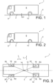
- a vehicle 1 according to the invention, of the type comprising a chassis 2 with controlled vertical position.
- They may nevertheless be other types of vehicles, preferably road transport vehicles.
- the chassis 2 also called “body”, carries or delimits a loading space 6 for the goods.
- this space 6 is delimited downwards by the chassis 2, to be as close as possible to the ground in the low support position of the chassis.
- this G1 ground clearance is less than 500 mm, and preferably between 150 and 500 mm.
- the vehicle 1 comprises only two running gear, namely a front running gear 8, and a rear running gear 10.
- Each of the two trains is equipped only with two single wheels, each of these wheels being individually articulated on the chassis 2 by a suspension arm, as will be described below.
- the design can be more complex. Indeed, it can for example be provided with a front axle where the two wheels are on the same axle, itself articulated by “pushed” or “pulled” suspension arms, generally two in number per wheel and mounted in up and down the axle to create a parallelogram kinematics.
- each of the wheels can be individually, or in pairs, articulated on the chassis 2 by at least one suspension arm in a “push” or “pull” configuration.
- the front axle 8 thus comprises a left front wheel R1 and a right front wheel R2, while the rear axle 10 comprises a left rear wheel R3 and a right rear wheel R4.
- Loadspace 6 features an extended rear overhang area. In practice, this leads to observing, in view from below as shown on the Figure 3 , that the vertical projection of the center of gravity 12 of the loaded vehicle is located at the rear of a crossing 14 between the two diagonals connecting the centers 16 of the treads 20 of the front and rear wheels R1-R4. In other words, the center of gravity 12 of the loaded vehicle is located behind relative to a mid-wheelbase between the two running gears 8, 10.
- loaded vehicle it is understood here that its loading space 6 is entirely occupied by goods all having the same surface mass.
- the longitudinal distance from the center of gravity 12, relative to the middle of the wheelbase corresponding to the intersection 14 between the diagonals, can be of the order of 50 cm to 1 m, and extend up to 2 m.
- the vehicle 1 has a longitudinal direction referenced "L” in the figures, as well as a transverse direction referenced "T".
- FIG. 4 an assembly is shown between one of the wheels of the vehicle, and the chassis 2. Here, it is the left rear wheel R3, but it is understood that the assembly is identical or similar for each of the four wheels R1-R4. Also, only the assembly of the R3 wheel will be described below.
- the wheel R3 comprises a rim 22, as well as a tire 24 arranged around the rim. It is the tire 24 which defines the tread 20.
- the rim 22 is articulated along an axis of wheel rotation 26 on a suspension arm 28, of generally rectangular shape.
- the articulation of the wheel R3 takes place at one of the vertices of the arm 28.
- the latter is pivotally mounted at another of its vertices on the chassis 2, along a parallel arm rotation axis 30. or substantially parallel to the axis of wheel rotation 26.
- an actuator 32 of the suspension arm is articulated. This articulation takes place along an actuator rotation axis 34, parallel to the axes 26, 30.
- the actuator 32 rests on the chassis 2, or also articulated thereon.
- This actuator 32 makes it possible to control the angular position of the suspension arm 28 relative to the chassis 2, in order to vary the vertical position of this chassis in the desired manner.
- the actuator 32 here is of the air cushion type. It is the control of its internal pressure which makes it possible to adjust its longitudinal extent between the arm 28 and the chassis 2, an extent which determines the angular position of this arm 28. This pressure is regulated by a control unit 33 of the vehicle, unit which can be common to all four wheels, while being capable of delivering different control signals depending on the wheels.
- the angular position of the suspension arm 28 is such that it forms an angle A1 relative to the chassis 2, this angle A1 being determined in side view between the normal to the chassis or the vertical, and a fictitious straight line connecting the two axes 26 , 30.
- the angle A1 adopted while the vehicle is rolling is for example of the order of 90°, but it can obviously be lower or higher.
- the suspension arm 28 being preferentially damped, the value of the angle A1 varies during the damping phases encountered during rolling.
- a shock absorber 36 is provided, of any design known to those skilled in the art. The opposite ends of the shock absorber 36 are articulated on the arm 28 and the chassis 2, along axes also parallel to the axes 26, 30, 34.
- This safety device is capable of limiting the accidental lowering of the chassis 2 on the ground 4, by adopting an active state in which it limits the rotation of the suspension arm around the axis 30, according to a first direction of rotation S1 corresponding to the clockwise direction on the Figure 4 . It is actually in this direction of rotation that the arm 28 leads to the lowering of the chassis 2 towards the ground 4.
- the security device 40 represented only schematically on the Figure 4 , is also articulated at its two opposite ends on the chassis 2 and on the suspension arm 28, along axes of rotation 42, 44 parallel to the axes 26, 30, 34.
- the safety device 40 is distinct from the shock absorber 36, but these two pieces of equipment can advantageously be merged, as will be described later.
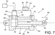
- the safety device 40 is shown in more detail, still in its active state preventing the accidental lowering of the chassis to the ground. It comprises a hydraulic cylinder 46, a cylinder 48 of which is hingedly mounted on the suspension arm 28 along the axis of rotation 42, and a piston 50 of which is hingedly mounted on the chassis 2 along the axis 44, or vice versa.
- the piston head 52 delimits on either side of it a first oil chamber 54, and a second oil chamber 56.
- the first chamber 54 is also defined by a bottom of the first chamber 58, while the second chamber 56 is also defined by a bottom of the second chamber 60 crossed by the rod of the piston 50.
- the first chamber 54 communicates with a first oil passage 62 made laterally through the cylinder 48. It also communicates with a second oil passage 64 made through the cylinder 48, this second passage being located close to the bottom of the first chamber 58, and in any case closer to this bottom 58 than is the first passage 62.
- the two passages 62, 64 are in fact spaced from one another in a sliding direction 66 of the piston in the cylinder.
- the second passage 64 communicates with a first oil pipe 68, while the first passage 62 communicates with a second oil pipe 70 connected to the end of the first pipe 68. Upstream of this connection, the first pipe 68 is equipped with a safety valve 72, this valve being able to be manual, but preferably being a solenoid valve controlled by the control unit 33.
- the second chamber 56 communicates with a third oil passage 74 produced laterally through the cylinder 48, this third passage being preferably arranged near the bottom of the second chamber 60.
- the third passage 74 communicates with the end a third oil pipe 76, belonging to a fluid circuit 78, which will be described below.
- the first fluid pipe communicates not only with the second pipe 70 connected to the first passage 62, but also with the other end of the third oil pipe 76 belonging to the fluidic circuit 78.
- the latter is completed by a tap on the third pipe 76, between its two ends, connection which leads to an oil tank 80 providing in its upper part an air reserve 82.
- the valve 72 In the active state of the security device 40 as shown on the Figure 5 , the valve 72 is held in the closed position. In this state, the oil cannot pass through the second passage 64, due to the closing of the valve 72. On the other hand, the oil can freely circulate between the two chambers 54, 56 via the first orifice 62, the second line 70, the third line 76, and the third passage 74. Consequently, the piston 50 can accompany the movements of the shock absorber during rolling, by moving its piston head 52 between the first and third passages 62, 74 Above all, in this active state of the safety device 40, the piston 50 is capable of stopping its travel in direction 66 to avoid excessive lowering of the chassis, and thus avoid its unwanted impact on the ground during rolling.
- the weight of the chassis 2 and the load of the vehicle cause a rotation of the suspension arm 28 along the axis 30 in the first direction S1, shown schematically by the arrow on the Figure 6 .
- the unwanted rotation of the suspension arm 28 causes a movement of the piston head 52 towards the bottom 58, driving the oil from the first chamber 54 via the first passage 62, towards the second chamber 56 via the pipes 70, 76 and the third passage 74.
- This blocking of the piston 50 in the safety position advantageously causes the accidental rotation of the suspension arm 28 to stop relative to the chassis 2, in the direction S1.
- This arm 28 then remains maintained in its safety position shown on the Figure 6 , which locally provides non-zero G2 ground clearance in order to avoid accidental contact with the ground.
- the latter forms an angle A2 with the normal to the chassis 2, this angle A2 being obviously less than the angle A1 described previously with reference to the Figure 4 .
- G2 can, for example, be increased by 10, 40 or 60%, and this increase is thus taken into account in the design of the safety devices associated with the wheels. Similar reasoning is carried out to avoid the risk of contact of the overhanging front part of the vehicle with the ground, during a failure of an actuator associated with a front wheel.
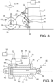
- the security device 40 can alternatively adopt an inactive state as represented on the figures 8 and 9 , in which the valve 72 is in the open position.
- this state adopted to voluntarily lower the chassis 2 to the ground the oil can be extracted from the first chamber 54 even after the passage of the piston head through the first passage 62, via the second passage 64 located near the bottom 58. This allows an additional stroke of the piston 50 beyond the first passage 62, to accompany an additional rotation of the arm 28 making it possible to bring the chassis 2 to the ground 4.
- the arm 28 When the chassis 2 reaches the ground, the arm 28 is in an angular position such that it forms an angle A3 with the normal to the chassis 2, this angle A3 shown on the figure 8 being obviously less than the angle A2 described previously with reference to the Figure 6 .
- a second preferred embodiment is shown in which the safety device 40 is integrated into the shock absorber 36, or vice versa.
- a single assembly fulfills the two safety and damping functions, this assembly being articulated at its ends at two points respectively on the suspension arm 28 and the chassis 2, along the axes 42, 44. result in this assembly fulfilling both functions, the shock absorber cylinder is formed by the cylinder 46 of the safety device 40, or vice versa.
- the second embodiment has the same characteristics as those of the first mode, to which equipment is added within the fluidic circuit 78.
- the third pipe 76 of this circuit is in fact equipped with a loop 84 arranged between the tap of the tank 80 , and his connection to the third passage 74.
- This loop 84 integrates elements to fulfill the shock absorber function. For this purpose, it integrates within a main conduit 90a a first non-return valve 86a, associated with a compression fluid passage orifice 88a.
- the loop also includes a conduit 90b for bypassing the compression fluid passage orifice 88a, this conduit 90b being equipped with a second non-return valve 86b associated with an expansion fluid passage orifice 88b.
- the second check valve 86b allows oil flow in a direction opposite to that of the first check valve 86a. Consequently, during the damping phase, the oil takes the main conduit 90a, while during the rebound phase, the oil takes the bypass conduit 90b.
- the oil passes through the compression fluid passage orifice 88a, which is calibrated so as to ensure energy dissipation and damping by rolling of the oil. Analogously, in expansion, the damping is determined by the passage of the oil into the other passage orifice 88b. Consequently, by providing that the two orifices 88a, 88b have different passage sections, differentiated damping in compression and rebound is advantageously obtained.
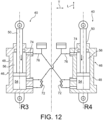
- the safety devices 40 of the different wheels of the vehicle can cooperate in pairs to provide an anti-roll function.
- FIG 12 shows the cooperation of the devices 40 for the two wheels R3, R4 of the rear running gear, but identical or similar cooperation can be adopted for the two wheels of the front running gear.
- the end of the third pipe 76 of the safety device 40 associated with the left rear wheel R3 no longer communicates with the third passage 74 of the cylinder 46 of this device 40, but it communicates with the third passage 74 of the cylinder 46 belonging to the safety device 40 associated with the right rear wheel R4, opposite transversely to the left rear wheel R3. Consequently, when the piston 50 of the right rear wheel R4 descends into its cylinder 48 following a rotation of the suspension arm of this wheel R4, the oil from the first chamber of the cylinder 54 associated with the wheel R4 is expelled in the direction of the second chamber 56 of the cylinder associated with the other wheel R3.
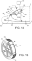
- the actuator 32 in the form of an air cushion is integrated into an assembly incorporating the safety device 40, with the latter being able to also incorporate the damping function in the sense described in reference to figures 10 and 11 .
- the longitudinal axis 92 of the air cushion coincides with an axis of the cylinder 46 of the safety device 40.
- a longitudinal end of the air cushion 32 is integral with the cylinder 48, while its longitudinal end opposite is pivotally mounted on the chassis 2, along the axis of rotation 44.
- the piston 50 has its rod pivotally mounted on the suspension arm 28, along the axis of rotation 42.
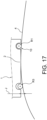
- This R3 wheel comprises, in addition to the rim 22 and the tire 24 defining the tread 20, a reinforcement 96 arranged radially around the rim.
- the reinforcement 96 is intended to be contacted by an interior part of the tread 20 of the tire, in the event of loss of pressure, thus avoiding direct contact between the tire 24 and the rim 22. It is designed rigid so as not to sag under the weight of the vehicle, thus helping to avoid the risk of accidental lowering of the chassis to the ground, in the event of loss of tire pressure, for example following a puncture.
- the ground clearance G2 provided locally at the level of the wheel by its safety device is preferentially greater than the maximum amplitude of sag of the wheel, following a loss of pressure in its tire which can result from deflation or of a burst.
- the principles set out above with reference to the figure 6' are also applicable to a situation of accumulation of a failure of an actuator associated with one of the wheels, and a loss of pressure in this wheel leading to rolling on the reinforcement 96.
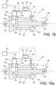
- each wheel is associated with a device for blocking rotation of the wheel suspension arm, this blocking device being here integrated into the safety device 40.
- a stop valve 98 preferably a solenoid valve controlled by the control unit.
- a manually operated shut-off valve is also possible, without departing from the scope of the invention.
- the stop valve 98 is arranged within the fluid circuit 78, on the third pipe 76 near the connection with the first and second pipes 68, 70.
- stop valves 98 preferably equipping the safety device 40 of each of the wheels, such risks are avoided for people located near the vehicle.
- the stop valve 98 can be arranged at another location on the third pipe 76, for example near the third oil passage 74 through the cylinder 48, as follows was represented on the figure 16a .
- this principle of installing the stop valve 98 for blocking the rotation of the suspension arm also applies to cases where the safety device 40 integrates the shock absorber function described with reference to the Figure 11 .
- the stop valve 98 can be installed upstream or downstream of the loop 84, without departing from the scope of the invention.
- the invention provides at least one embodiment in which the safety device associated with each wheel integrates several of the additional functions described previously, or even all of them, namely the shock absorber function, the anti-roll function, the integration function of the actuator, and the function of blocking rotation of the suspension arm by blocking translation of the piston.
- the vehicle 1 is shown in driving configuration, that is to say with its chassis 2 in the high driving position defining the ground clearance G1.
- the particularity of the vehicle lies in the fact that the kinematics associated with each of the four wheels are identical. More precisely, these identical kinematics make it possible to generate an identical or substantially identical longitudinal offset of the chassis 2 relative to the ground 4, when this chassis is lowered. Thanks to this design, the lowering of the chassis towards its low support position on the ground does not generate stress in the running gears 8, 10, even when all the wheels are blocked by a parking brake during this lowering .
- the tolerated deviations are such that when they are combined, the difference in longitudinal offset induced on the chassis between the lowest offset among the four wheels, and the highest offset, n does not exceed 5 cm, or even 2 or 3 cm.
- This small offset difference can in fact be absorbed by moderate sliding of the tires on the ground during lowering, without causing harmful stresses on the running gear, even with all four wheels blocked by the parking brake.
- the method begins with a step E1 of waiting for receipt of an order to lower the chassis.
- This order can be triggered by an operator, for example via a dedicated button on the dashboard, or any other button connected to the control unit 33 of the vehicle.
- step E2 consists of checking that the wheels of the front axle do not have too high a steering angle, because otherwise, this could lead to the vehicle rotating during lowering the chassis. Thus, if the steering angle is greater than a safe value, a step E'2 is implemented to restore the steering until a suitable steering angle is obtained.
- This step E'2 can be carried out automatically using a motorized steering system, or manually by the operator, by acting directly on the steering wheel of the vehicle.
- step E3 can be implemented, consisting of actuation of the parking brake only for the wheels R3, R4 of the rear running gear.
- step E4 consists of switching all the safety valves 72 from their closed position to their open position, so as to place the security devices 40 in the inactive state.
- Step E5 then consists of lowering the chassis 2, by controlling the actuators 32, still via the unit 33 of the vehicle. Moreover, this unit 33 can be programmed to successively implement all of the steps of this process, automatically, that is to say without operator intervention. The lowering step E5 is continued until the chassis 2 rests on the ground 4, in its low support position.
- a step E6 of safely loading the tires of the wheels can be carried out.
- This optional step aims to ensure that the tires are not completely unloaded following the support of the chassis on the ground. It is for example implemented by operating a lifting control of the chassis 2 via the actuators 32, so as to cause a small vertical relative movement between this chassis and the axis of rotation of each wheel. This vertical movement normally does not exceed more than a few millimeters, in order to avoid a loss of contact between the chassis 2 and the ground 4.
- loading the tires on the ground reinforces the overall grip of the vehicle in position. lower support of its chassis. The risk of the vehicle sliding is reduced, which remains particularly advantageous when the vehicle is lowered on sloping ground.
- step E7 can be implemented, consisting of actuation of the parking brake for the wheels R1, R2 of the front running gear, with the parking brake kept activated for the wheels of the rear axle. .
- step E8 lies in the activation of the devices 98 for blocking the rotation of the wheel suspension arms 28, in order to avoid the risk of parasitic movements of the chassis during unloading/loading of goods operations.
- step E7 of actuating the parking brake for the wheels R1, R2 of the front running gear could be carried out after step E8 of activating the devices 98 for blocking the rotation of the wheel suspension arms 28 , without departing from the scope of the invention. It is the same for stages E3 and E4, or even for stages E2-E'2 and E3.
Landscapes
- Engineering & Computer Science (AREA)
- Mechanical Engineering (AREA)
- Transportation (AREA)
- Vehicle Body Suspensions (AREA)
Claims (18)
- Fahrzeug (1), umfassend ein Fahrgestell (2) mit gesteuerter vertikaler Position, so dass es zwischen einer hohen Fahrposition und einer niedrigen Abstützposition des Fahrgestells auf dem Boden (4) bewegt werden kann, wobei das Fahrzeug ebenfalls eine Vielzahl von Rädern (R1-R4) umfasst und jedem Rad Folgendes zugeordnet ist:- ein Aufhängungsarm (28), der das Rad trägt, wobei der Arm schwenkbar am Fahrgestell (2) montiert ist;- ein Aufhängungsarm-Stellglied (32), das zwischen dem Aufhängungsarm (28) und dem Fahrgestell (2) angeordnet ist, wobei das Stellglied es ermöglicht, eine Winkelposition des Arms im Verhältnis zum Fahrgestell zu steuern, um die vertikale Position des Fahrgestells zu variieren;dadurch gekennzeichnet, dass es Folgendes umfasst:- eine Sicherheitsvorrichtung (40), die das unbeabsichtigte Absenken des Fahrgestells (2) begrenzen kann, wobei die Vorrichtung einerseits einen aktiven Zustand, in dem sie es ermöglicht, die Drehung des Aufhängungsarms (28) in einer ersten Richtung (S1) zu begrenzen, die zum Absenken des Fahrgestells bis zu einer Sicherheitsposition des Arms führt, und andererseits einen inaktiven Zustand annehmen kann, in dem sie die Drehung des Arms (28) in der ersten Richtung (S1) über die Sicherheitsposition hinaus gestattet,
wobei die Sicherheitsvorrichtung (40) einen Stellantrieb (46) aufweist, von dem ein Zylinder (48) am Fahrgestell (2) montiert ist und ein Kolben (50) am Aufhängungsarm (28) montiert ist oder umgekehrt, wobei der Stellantrieb eine erste Kammer (54) definiert, die mit einem ersten (62) und einem zweiten Fluiddurchgang (64) durch den Zylinder (48) in Verbindung steht, die in einer Gleitrichtung (66) des Kolbens im Zylinder voneinander beabstandet ist, so dass sich der zweite Durchgang (64) am nächsten an einer Unterseite (58) der durch den Zylinder definierten ersten Kammer befindet, wobei der zweite Durchgang (64) mit einer ersten Fluidleitung (68) in Verbindung steht, die mit einem Sicherheitsventil (72) ausgestattet ist, das Folgendes einnimmt:- eine offene Position im inaktiven Zustand der Sicherheitsvorrichtung (40), um das Abfließen des Fluids aus der ersten Kammer (54) durch den zweiten Durchgang (64) während einer Bewegung des Kolbens (50) in Richtung der Unterseite (58) der ersten Kammer zu ermöglichen, die durch die Drehung des Aufhängungsarms (28) in der ersten Richtung (S1) verursacht wird; und- eine geschlossene Position im aktiven Zustand der Sicherheitsvorrichtung (40), so dass bei einer Bewegung des Kolbens (50) in Richtung der Unterseite (58) der ersten Kammer, die durch die Drehung des Aufhängungsarms (28) in der ersten Richtung (S1) verursacht wird, der Kolben (50) in einer Sicherheitsposition im Abstand von der Unterseite (58) der ersten Kammer blockiert, eine Position, in der das Fluid zwischen dem Kolbenkopf (52) und dem Sicherheitsventil (72) komprimiert wird. - Fahrzeug nach Anspruch 1, dadurch gekennzeichnet, dass das Fahrzeug jedem Rad (R1-R4) zugeordnet einen Stoßdämpfer (36) aufweist, der zwischen dem Fahrgestell (2) und dem Aufhängungsarm (28) des Rades angeordnet ist.
- Fahrzeug nach Anspruch 2, dadurch gekennzeichnet, dass der Stoßdämpfer (36) durch ein von der Sicherheitsvorrichtung (40) verschiedenes Element gebildet wird.
- Fahrzeug nach Anspruch 2, dadurch gekennzeichnet, dass die Sicherheitsvorrichtung (40) in den Stoßdämpfer (36) integriert ist, wobei letzterer einen durch den Stellantrieb (46) der Sicherheitsvorrichtung gebildeten Stellantrieb aufweist.
- Fahrzeug nach einem der vorhergehenden Ansprüche, dadurch gekennzeichnet, dass der Stellantrieb (46) eine zweite Kammer (56) definiert, die von der ersten Kammer (54) durch den Kolbenkopf (52) getrennt ist, wobei die zweite Kammer (56) über den Zylinder (48) mit einem dritten Fluiddurchgang (74) in Verbindung steht, und dadurch, dass die erste Fluidleitung (68) stromabwärts des Sicherheitsventils (72) in Strömungsrichtung vom zweiten Durchgang (64) zu dem Sicherheitsventil (72) hin einerseits mit einer zweiten Fluidleitung (70), die mit dem ersten Durchgang (62) verbunden ist, und andererseits mit einem Fluidkreislauf (78) in Verbindung steht.
- Fahrzeug nach Anspruch 5, dadurch gekennzeichnet, dass der Fluidkreislauf (78) über den Zylinder (48) mit dem dritten Fluiddurchgang (74) in Verbindung steht.
- Fahrzeug nach Anspruch 5, dadurch gekennzeichnet, dass der Fluidkreislauf (78) mit dem dritten Fluiddurchgang (74) des Stellantriebs (46) in Verbindung steht, der zu der Sicherheitsvorrichtung (40) gehört, die dem Rad des Fahrzeugs zugeordnet ist, das sich in einer Querrichtung (T) des Fahrzeugs gegenüberliegend befindet.
- Fahrzeug nach einem der Ansprüche 5 bis 7, dadurch gekennzeichnet, dass der Fluidkreislauf (78) eine erste Rückschlagklappe (86a), die einer Durchgangsöffnung für Fluid unter Druck (88a) zugeordnet ist, sowie eine Leitung (90b) zum Umgehen der Durchgangsöffnung für Fluid unter Druck (88a) umfasst, wobei die Umgehungsleitung (90b) mit einer zweiten Rückschlagklappe (86b) ausgestattet ist, die einer Durchgangsöffnung für Fluid in Ausdehnung (88b) zugeordnet ist, wobei die zweite Rückschlagklappe (86b) eine Fluidströmung in einer Richtung ermöglicht, die entgegengesetzt zu der der ersten Rückschlagklappe (86a) ist, und die Durchgangsöffnung für Fluid unter Druck (88a) einen Durchgangsabschnitt aufweist, der sich von dem der Durchgangsöffnung für Fluid in Ausdehnung (88b) unterscheidet.
- Fahrzeug nach einem der Ansprüche 5 bis 8, dadurch gekennzeichnet, dass der Fluidkreislauf (78) ein Fluidreservoir (80) mit einem Luftvorrat (82) aufweist.
- Fahrzeug nach einem der vorhergehenden Ansprüche, dadurch gekennzeichnet, dass das Aufhängungsarm-Stellglied (32) ein Luftkissen mit Längsachse (92) ist, welche mit einer Achse des Stellantriebs (46) der Sicherheitsvorrichtung (40) zusammenfällt, wobei ein Längsende des Luftkissens (32) fest mit einem der beiden Elemente des Stellantriebs aus Zylinder (48) und Kolben (50) verbunden ist, während das andere der beiden Elemente des Stellantriebs an einer der beiden Einheiten aus Aufhängungsarm (28) und Fahrgestell (2) montiert ist, und das gegenüberliegende Längsende des Luftkissens (32) an der anderen der beiden Einheiten aus Aufhängungsarm (28) und Fahrgestell (2) montiert ist.
- Fahrzeug nach einem der vorhergehenden Ansprüche, dadurch gekennzeichnet, dass der Stellantrieb (46) ein Hydraulikzylinder ist.
- Fahrzeug nach einem der vorhergehenden Ansprüche, dadurch gekennzeichnet, dass jedes Rad (R1-R4) eine Felge (22) und einen Reifen (24) sowie eine um die Felge (22) angeordnete Verstärkung (96) aufweist und dazu bestimmt ist, von einer Lauffläche (20) des Reifens bei Druckverlust berührt zu werden.
- Fahrzeug nach einem der vorhergehenden Ansprüche, dadurch gekennzeichnet, dass es mindestens eines der folgenden Merkmale umfasst:- das Fahrzeug umfasst nur zwei Radaufhängungen, nämlich eine vordere Radaufhängung (8) und eine hintere Radaufhängung (10), von denen jede vorzugsweise nur mit zwei Rädern in Einfachbereifung ausgestattet ist, wobei jedes dieser Räder (R1-R4) einzeln über seinen Aufhängungsarm (28) am Fahrgestell angelenkt ist;- das Fahrzeug weist in Transportkonfiguration eine Bodenfreiheit (G1) von weniger als 500 mm;- der Schwerpunkt (12) des beladenen Fahrzeugs befindet sich, von unten gesehen, bezogen auf eine Mitte des Radstands (14) hinten zwischen einer vorderen Radaufhängung (8) und einer hinteren Radaufhängung (10);- das Fahrzeug weist einen Güterladeraum (6) auf und bildet vorzugsweise einen städtischen Lieferwagen.
- Fahrzeug nach einem der vorhergehenden Ansprüche, dadurch gekennzeichnet, dass es außerdem jedem Rad (R1-R4) zugeordnet eine Drehblockierungsvorrichtung (98) für seinen Aufhängungsarm (28) aufweist, wobei die Blockierungsvorrichtung dazu konfiguriert ist, die Drehung des Aufhängungsarms (28) im Verhältnis zum Fahrgestell (2) in beide Drehrichtungen zu verhindern, wenn das Fahrgestell (2) sich in einer niedrigen Abstützposition auf dem Boden befindet.
- Fahrzeug nach Anspruch 14 in Kombination mit Anspruch 5, dadurch gekennzeichnet, dass die Drehblockierungsvorrichtung für den Aufhängungsarm ein Absperrventil (98) ist, das einen integralen Bestandteil des Fluidkreislaufs (78) der Sicherheitsvorrichtung (40) darstellt, wobei das Ventil in der Absperrposition die Bewegung des Kolbens (50) im Zylinder (48) in beide Richtungen seiner Gleitrichtung (66) unterbindet.
- Fahrzeug nach einem der vorhergehenden Ansprüche, dadurch gekennzeichnet, dass für jedes Rad (R1-R4) des Fahrzeugs in der hohen Fahrposition des Fahrgestells (2):- sein Aufhängungsarm (28) eine Armdrehachse (30) im Verhältnis zum Fahrgestell (2) aufweist;- das Rad eine Raddrehachse (26) in Bezug auf den Aufhängungsarm (28) aufweist, wobei die Armdrehachse und die Raddrehachse (30, 26) parallel oder im Wesentlichen parallel sind;- sein Aufhängungsarm (28) eine Armlänge (LB) aufweist, die zwischen der Armdrehachse und der Raddrehachse (30, 26) definiert ist;- die Armdrehachse (30) einen ersten vertikalen Abstand zum Boden (DV1) aufweist;- die Raddrehachse (26) einen zweiten vertikalen Abstand zum Boden (DV2) aufweist; und- das Rad eine Lauffläche (20) mit einem Raddurchmesser (D) umfasst,und dadurch, dass für alle Räder (R1-R4):- die Armdrehachse (30) in Längsrichtung von der Raddrehachse (26) in derselben Richtung versetzt ist;- die Armlänge (LB) gleich oder im Wesentlichen gleich ist;- der erste vertikale Abstand zum Boden (DV1) gleich oder im Wesentlichen gleich ist;- der zweite vertikale Abstand zum Boden (DV2) gleich oder im Wesentlichen gleich ist; und- der Raddurchmesser (D) gleich oder im Wesentlichen gleich ist.
- Verfahren zum Absenken eines Fahrgestells (2) des Fahrzeugs auf den Boden nach einem der vorhergehenden Ansprüche, dadurch gekennzeichnet, dass es einen Schritt des Kippens des Sicherheitsventils (72) jedes Rads von seiner geschlossenen Position in seine offene Position und anschließend einen Schritt des Steuerns der Stellglieder (32) umfasst, um das Absenken des Fahrgestells (2) in Richtung des Bodens (4) anzutreiben.
- Verfahren nach dem vorhergehenden Anspruch, das mit einem Fahrzeug durchgeführt wird, das nur zwei Radaufhängungen umfasst, nämlich eine vordere Radaufhängung (8) und eine hintere Radaufhängung (10), wobei jedes Rad (R1-R4) der Radaufhängungen (8, 10) einer Feststellbremse zugeordnet ist, dadurch gekennzeichnet, dass es die folgenden aufeinanderfolgenden Schritte umfasst:- wenn sich das Fahrgestell (2) in der hohen Fahrposition befindet, Aktivieren der Feststellbremse nur für alle Räder (R3, R4) einer der beiden Radaufhängungen (10);- Absenken des Fahrgestells (2) bis in seine niedrige Abstützposition auf dem Boden (4); und- Betätigen der Feststellbremse für alle Räder (R1, R2) der anderen der beiden Radaufhängungen (8).
Applications Claiming Priority (2)
| Application Number | Priority Date | Filing Date | Title |
|---|---|---|---|
| FR2000123A FR3105953B1 (fr) | 2020-01-08 | 2020-01-08 | Vehicule comprenant un chassis a position verticale commandee, pour pouvoir etre abaisse dans une position basse d’appui sur le sol |
| PCT/FR2021/050002 WO2021140290A1 (fr) | 2020-01-08 | 2021-01-04 | Vehicule comprenant un chassis a position verticale commandee, pour pouvoir etre abaisse dans une position basse d'appui sur le sol |
Publications (2)
| Publication Number | Publication Date |
|---|---|
| EP4087743A1 EP4087743A1 (de) | 2022-11-16 |
| EP4087743B1 true EP4087743B1 (de) | 2024-03-06 |
Family
ID=69903622
Family Applications (1)
| Application Number | Title | Priority Date | Filing Date |
|---|---|---|---|
| EP21705232.3A Active EP4087743B1 (de) | 2020-01-08 | 2021-01-04 | Fahrzeug mit einem chassis mit geregelter vertikaler lage, um in eine auf dem boden abgestützte niedrige position abgesenkt zu werden |
Country Status (5)
| Country | Link |
|---|---|
| US (1) | US11780284B2 (de) |
| EP (1) | EP4087743B1 (de) |
| JP (1) | JP2023509199A (de) |
| FR (1) | FR3105953B1 (de) |
| WO (1) | WO2021140290A1 (de) |
Families Citing this family (4)
| Publication number | Priority date | Publication date | Assignee | Title |
|---|---|---|---|---|
| IT202000011707A1 (it) * | 2020-05-20 | 2021-11-20 | Ferrari Spa | Automobile sportiva ad alte prestazioni e relativo metodo di controllo |
| IT202100003494A1 (it) * | 2021-02-16 | 2022-08-16 | Italcarrelli S P A | Veicolo semovente per la movimentazione di cavalletti porta-lastre |
| EP4079613A1 (de) * | 2021-04-22 | 2022-10-26 | Volvo Truck Corporation | Fahrzeug und verfahren zur begrenzung des wankens eines fahrzeugs |
| US20230150331A1 (en) * | 2021-11-15 | 2023-05-18 | Sony Group Corporation | Vehicle with suspension-controlled motion resistance members |
Family Cites Families (7)
| Publication number | Priority date | Publication date | Assignee | Title |
|---|---|---|---|---|
| US4145073A (en) * | 1977-04-07 | 1979-03-20 | Caterpillar Tractor Co. | Lockup system for a vehicle suspension mechanism |
| GB0007625D0 (en) * | 2000-03-30 | 2000-05-17 | Gibbs Tech Ltd | Improved suspension strut |
| WO2004106110A1 (en) * | 2003-06-03 | 2004-12-09 | Gemco Mobile Systems B.V. | Wheel suspension and vehicle |
| JP7397850B2 (ja) * | 2018-07-25 | 2023-12-13 | タダノ デマグ ゲーエムベーハー | ハイドロニューマチックサスペンションおよび少なくとも2つのブレーキ回路を備えるブレーキシステムを有する車載クレーン |
| US20210061040A1 (en) * | 2019-08-30 | 2021-03-04 | Aktv8, Llc | Height adjustment system |
| US20220402482A1 (en) * | 2019-11-22 | 2022-12-22 | Volvo Truck Corporation | Methods and systems for monitoring vehicle load distribution |
| WO2022140657A1 (en) * | 2020-12-23 | 2022-06-30 | Clearmotion,Inc. | Systems and methods for vehicle control using terrain-based localization |
-
2020
- 2020-01-08 FR FR2000123A patent/FR3105953B1/fr active Active
-
2021
- 2021-01-04 WO PCT/FR2021/050002 patent/WO2021140290A1/fr unknown
- 2021-01-04 US US17/791,431 patent/US11780284B2/en active Active
- 2021-01-04 JP JP2022542016A patent/JP2023509199A/ja active Pending
- 2021-01-04 EP EP21705232.3A patent/EP4087743B1/de active Active
Also Published As
| Publication number | Publication date |
|---|---|
| FR3105953B1 (fr) | 2022-01-21 |
| JP2023509199A (ja) | 2023-03-07 |
| US11780284B2 (en) | 2023-10-10 |
| FR3105953A1 (fr) | 2021-07-09 |
| WO2021140290A1 (fr) | 2021-07-15 |
| EP4087743A1 (de) | 2022-11-16 |
| US20230038742A1 (en) | 2023-02-09 |
Similar Documents
| Publication | Publication Date | Title |
|---|---|---|
| EP4087743B1 (de) | Fahrzeug mit einem chassis mit geregelter vertikaler lage, um in eine auf dem boden abgestützte niedrige position abgesenkt zu werden | |
| EP1773609B1 (de) | Kraftfahrzeug mit begrenztem neigewinkel | |
| EP0960045B1 (de) | Führungssystem entlang mindestens einer bodenschiene für eine achse eines strassenfahrzeugs | |
| EP0176442A1 (de) | Verlängerbare Anhängerkupplung für Strassenfahrzeuge und Schienenfahrzeuge | |
| EP2098387B1 (de) | Reinigungsfahrzeug | |
| EP3638521A1 (de) | Kupplungsvorrichtung, vier freiheitsgraden umfassend | |
| FR3105954A1 (fr) | Vehicule comprenant un chassis a position verticale commandee, et des dispositifs de blocage en rotation des bras de suspension lorsque le chassis se trouve en position basse d’appui sur le sol | |
| EP4118019B1 (de) | Vorrichtung zum blockieren eines strassenfahrzeugs vor einer be-/entladestelle | |
| EP1137568B1 (de) | Einspuhrfahrzeug mit von der geschwindigkeit abhängigen, ausschwenkbaren stabilisierungsrädern | |
| WO2021140293A1 (fr) | Procede ameliore d'abaissement d'un chassis de vehicule a position verticale commandee | |
| FR3105952A1 (fr) | Véhicule comprenant un châssis à position verticale commandée, présentant une conception limitant l’introduction de contraintes dans les trains roulants au cours de l’abaissement du châssis | |
| CA2545784C (fr) | Vehicule lourd | |
| EP0440083B1 (de) | Vorrichtung zur Regulierung der Starrheit eines Reifens und Fahrzeug ausgerüstet mit solch einer Vorrichtung | |
| WO2018078232A1 (fr) | Procédé de contrôle de l'inclinaison d'un véhicule inclinable par action sur un dispositif de suspension hydropneumatique | |
| EP1996415B1 (de) | Fahrzeug mit einer aufhängungsvorrichtung mit variablem radsturz | |
| EP2152562B1 (de) | Bidirektionales führungssystem mit seitlicher schwingungsbegrenzung für eine durch eine schiene in der erde geführte strassenachse | |
| EP0935538B1 (de) | Niveauregeleinrichtung | |
| FR2694730A1 (fr) | Dispositif de commande de sécurité pour véhicule industriel ayant une partie mobile, notamment pour véhicule à benne basculante. | |
| EP3642059B1 (de) | Koppelbares kraftfahrzeug-strassenfahrzeug | |
| WO2022248627A1 (fr) | Atterrisseur d'aeronef dote d'au moins une roue motorisee | |
| EP3922487A1 (de) | Verbesserte ankupplungsvorrichtung mit vier freiheitsgraden | |
| FR3080819A1 (fr) | Vehicule pendulaire avec freins de parking sur un essieu a deux roues maintenant son inclinaison | |
| FR2894553A1 (fr) | Train roulant auto-vireur pour remorque | |
| FR2894552A1 (fr) | Train roulant auto-vireur pour remorque | |
| FR2486003A1 (fr) | Procede de freinage de securite pour vehicules motorises ou remorques |
Legal Events
| Date | Code | Title | Description |
|---|---|---|---|
| STAA | Information on the status of an ep patent application or granted ep patent |
Free format text: STATUS: UNKNOWN |
|
| STAA | Information on the status of an ep patent application or granted ep patent |
Free format text: STATUS: THE INTERNATIONAL PUBLICATION HAS BEEN MADE |
|
| PUAI | Public reference made under article 153(3) epc to a published international application that has entered the european phase |
Free format text: ORIGINAL CODE: 0009012 |
|
| STAA | Information on the status of an ep patent application or granted ep patent |
Free format text: STATUS: REQUEST FOR EXAMINATION WAS MADE |
|
| 17P | Request for examination filed |
Effective date: 20220805 |
|
| AK | Designated contracting states |
Kind code of ref document: A1 Designated state(s): AL AT BE BG CH CY CZ DE DK EE ES FI FR GB GR HR HU IE IS IT LI LT LU LV MC MK MT NL NO PL PT RO RS SE SI SK SM TR |
|
| DAV | Request for validation of the european patent (deleted) | ||
| DAX | Request for extension of the european patent (deleted) | ||
| GRAP | Despatch of communication of intention to grant a patent |
Free format text: ORIGINAL CODE: EPIDOSNIGR1 |
|
| STAA | Information on the status of an ep patent application or granted ep patent |
Free format text: STATUS: GRANT OF PATENT IS INTENDED |
|
| INTG | Intention to grant announced |
Effective date: 20230914 |
|
| GRAS | Grant fee paid |
Free format text: ORIGINAL CODE: EPIDOSNIGR3 |
|
| GRAA | (expected) grant |
Free format text: ORIGINAL CODE: 0009210 |
|
| STAA | Information on the status of an ep patent application or granted ep patent |
Free format text: STATUS: THE PATENT HAS BEEN GRANTED |
|
| AK | Designated contracting states |
Kind code of ref document: B1 Designated state(s): AL AT BE BG CH CY CZ DE DK EE ES FI FR GB GR HR HU IE IS IT LI LT LU LV MC MK MT NL NO PL PT RO RS SE SI SK SM TR |
|
| REG | Reference to a national code |
Ref country code: CH Ref legal event code: EP |
|
| REG | Reference to a national code |
Ref country code: DE Ref legal event code: R096 Ref document number: 602021010115 Country of ref document: DE |
|
| REG | Reference to a national code |
Ref country code: IE Ref legal event code: FG4D Free format text: LANGUAGE OF EP DOCUMENT: FRENCH |
|
| REG | Reference to a national code |
Ref country code: NL Ref legal event code: FP |