EP4087033A1 - Batterie secondaire du type bouton - Google Patents
Batterie secondaire du type bouton Download PDFInfo
- Publication number
- EP4087033A1 EP4087033A1 EP21842476.0A EP21842476A EP4087033A1 EP 4087033 A1 EP4087033 A1 EP 4087033A1 EP 21842476 A EP21842476 A EP 21842476A EP 4087033 A1 EP4087033 A1 EP 4087033A1
- Authority
- EP
- European Patent Office
- Prior art keywords
- distal end
- sidewall
- button
- secondary battery
- flat portion
- Prior art date
- Legal status (The legal status is an assumption and is not a legal conclusion. Google has not performed a legal analysis and makes no representation as to the accuracy of the status listed.)
- Pending
Links
- 238000010168 coupling process Methods 0.000 description 3
- 239000003792 electrolyte Substances 0.000 description 3
- 230000008878 coupling Effects 0.000 description 2
- 238000005859 coupling reaction Methods 0.000 description 2
- 239000002184 metal Substances 0.000 description 2
- 238000005452 bending Methods 0.000 description 1
- 238000007599 discharging Methods 0.000 description 1
- 230000000694 effects Effects 0.000 description 1
- 230000005611 electricity Effects 0.000 description 1
- 238000012986 modification Methods 0.000 description 1
- 230000004048 modification Effects 0.000 description 1
- 238000007789 sealing Methods 0.000 description 1
- 238000000926 separation method Methods 0.000 description 1
- 238000009751 slip forming Methods 0.000 description 1
Images

Classifications
-
- H—ELECTRICITY
- H01—ELECTRIC ELEMENTS
- H01M—PROCESSES OR MEANS, e.g. BATTERIES, FOR THE DIRECT CONVERSION OF CHEMICAL ENERGY INTO ELECTRICAL ENERGY
- H01M50/00—Constructional details or processes of manufacture of the non-active parts of electrochemical cells other than fuel cells, e.g. hybrid cells
- H01M50/10—Primary casings; Jackets or wrappings
- H01M50/147—Lids or covers
- H01M50/166—Lids or covers characterised by the methods of assembling casings with lids
-
- H—ELECTRICITY
- H01—ELECTRIC ELEMENTS
- H01M—PROCESSES OR MEANS, e.g. BATTERIES, FOR THE DIRECT CONVERSION OF CHEMICAL ENERGY INTO ELECTRICAL ENERGY
- H01M10/00—Secondary cells; Manufacture thereof
- H01M10/04—Construction or manufacture in general
-
- H—ELECTRICITY
- H01—ELECTRIC ELEMENTS
- H01M—PROCESSES OR MEANS, e.g. BATTERIES, FOR THE DIRECT CONVERSION OF CHEMICAL ENERGY INTO ELECTRICAL ENERGY
- H01M10/00—Secondary cells; Manufacture thereof
- H01M10/04—Construction or manufacture in general
- H01M10/0422—Cells or battery with cylindrical casing
- H01M10/0427—Button cells
-
- H—ELECTRICITY
- H01—ELECTRIC ELEMENTS
- H01M—PROCESSES OR MEANS, e.g. BATTERIES, FOR THE DIRECT CONVERSION OF CHEMICAL ENERGY INTO ELECTRICAL ENERGY
- H01M10/00—Secondary cells; Manufacture thereof
- H01M10/04—Construction or manufacture in general
- H01M10/0431—Cells with wound or folded electrodes
-
- H—ELECTRICITY
- H01—ELECTRIC ELEMENTS
- H01M—PROCESSES OR MEANS, e.g. BATTERIES, FOR THE DIRECT CONVERSION OF CHEMICAL ENERGY INTO ELECTRICAL ENERGY
- H01M50/00—Constructional details or processes of manufacture of the non-active parts of electrochemical cells other than fuel cells, e.g. hybrid cells
- H01M50/10—Primary casings; Jackets or wrappings
- H01M50/102—Primary casings; Jackets or wrappings characterised by their shape or physical structure
- H01M50/109—Primary casings; Jackets or wrappings characterised by their shape or physical structure of button or coin shape
-
- H—ELECTRICITY
- H01—ELECTRIC ELEMENTS
- H01M—PROCESSES OR MEANS, e.g. BATTERIES, FOR THE DIRECT CONVERSION OF CHEMICAL ENERGY INTO ELECTRICAL ENERGY
- H01M50/00—Constructional details or processes of manufacture of the non-active parts of electrochemical cells other than fuel cells, e.g. hybrid cells
- H01M50/10—Primary casings; Jackets or wrappings
- H01M50/147—Lids or covers
- H01M50/148—Lids or covers characterised by their shape
- H01M50/153—Lids or covers characterised by their shape for button or coin cells
-
- H—ELECTRICITY
- H01—ELECTRIC ELEMENTS
- H01M—PROCESSES OR MEANS, e.g. BATTERIES, FOR THE DIRECT CONVERSION OF CHEMICAL ENERGY INTO ELECTRICAL ENERGY
- H01M50/00—Constructional details or processes of manufacture of the non-active parts of electrochemical cells other than fuel cells, e.g. hybrid cells
- H01M50/10—Primary casings; Jackets or wrappings
- H01M50/183—Sealing members
-
- H—ELECTRICITY
- H01—ELECTRIC ELEMENTS
- H01M—PROCESSES OR MEANS, e.g. BATTERIES, FOR THE DIRECT CONVERSION OF CHEMICAL ENERGY INTO ELECTRICAL ENERGY
- H01M50/00—Constructional details or processes of manufacture of the non-active parts of electrochemical cells other than fuel cells, e.g. hybrid cells
- H01M50/40—Separators; Membranes; Diaphragms; Spacing elements inside cells
- H01M50/46—Separators, membranes or diaphragms characterised by their combination with electrodes
-
- H—ELECTRICITY
- H01—ELECTRIC ELEMENTS
- H01M—PROCESSES OR MEANS, e.g. BATTERIES, FOR THE DIRECT CONVERSION OF CHEMICAL ENERGY INTO ELECTRICAL ENERGY
- H01M50/00—Constructional details or processes of manufacture of the non-active parts of electrochemical cells other than fuel cells, e.g. hybrid cells
- H01M50/40—Separators; Membranes; Diaphragms; Spacing elements inside cells
- H01M50/471—Spacing elements inside cells other than separators, membranes or diaphragms; Manufacturing processes thereof
- H01M50/474—Spacing elements inside cells other than separators, membranes or diaphragms; Manufacturing processes thereof characterised by their position inside the cells
-
- H—ELECTRICITY
- H01—ELECTRIC ELEMENTS
- H01M—PROCESSES OR MEANS, e.g. BATTERIES, FOR THE DIRECT CONVERSION OF CHEMICAL ENERGY INTO ELECTRICAL ENERGY
- H01M2220/00—Batteries for particular applications
- H01M2220/30—Batteries in portable systems, e.g. mobile phone, laptop
-
- Y—GENERAL TAGGING OF NEW TECHNOLOGICAL DEVELOPMENTS; GENERAL TAGGING OF CROSS-SECTIONAL TECHNOLOGIES SPANNING OVER SEVERAL SECTIONS OF THE IPC; TECHNICAL SUBJECTS COVERED BY FORMER USPC CROSS-REFERENCE ART COLLECTIONS [XRACs] AND DIGESTS
- Y02—TECHNOLOGIES OR APPLICATIONS FOR MITIGATION OR ADAPTATION AGAINST CLIMATE CHANGE
- Y02E—REDUCTION OF GREENHOUSE GAS [GHG] EMISSIONS, RELATED TO ENERGY GENERATION, TRANSMISSION OR DISTRIBUTION
- Y02E60/00—Enabling technologies; Technologies with a potential or indirect contribution to GHG emissions mitigation
- Y02E60/10—Energy storage using batteries
-
- Y—GENERAL TAGGING OF NEW TECHNOLOGICAL DEVELOPMENTS; GENERAL TAGGING OF CROSS-SECTIONAL TECHNOLOGIES SPANNING OVER SEVERAL SECTIONS OF THE IPC; TECHNICAL SUBJECTS COVERED BY FORMER USPC CROSS-REFERENCE ART COLLECTIONS [XRACs] AND DIGESTS
- Y02—TECHNOLOGIES OR APPLICATIONS FOR MITIGATION OR ADAPTATION AGAINST CLIMATE CHANGE
- Y02P—CLIMATE CHANGE MITIGATION TECHNOLOGIES IN THE PRODUCTION OR PROCESSING OF GOODS
- Y02P70/00—Climate change mitigation technologies in the production process for final industrial or consumer products
- Y02P70/50—Manufacturing or production processes characterised by the final manufactured product
Definitions
- the present invention relates to a button-type secondary battery having a shape having a diameter greater than a height thereof, and more particularly, to a button-type secondary battery in which an upper can and a lower can are more strongly coupled to each other by bending an end of the upper can to be fixed to a bottom surface of the lower can.
- a button-type battery commonly used as a coin-type battery or a button-type battery has a thin button shape of which a diameter is greater than a height and is widely used in various devices such as remote controllers, clocks, toys, computer parts, and the like.
- Such a button-type battery is mainly manufactured as a non-rechargeable primary battery, but is also widely manufactured as a secondary battery that is chargeable and dischargeable as miniaturized devices are developed. Also, the button-type secondary battery also has a structure in which an electrode assembly and an electrolyte are embedded in a case to repeatedly perform charging and discharging, like the button-type secondary battery or the cylindrical or pouch-type secondary battery.
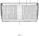
- FIG. 1 is a cross-sectional view of a button-type secondary battery according to a related art.
- a button-type secondary battery has a structure, in which an upper can 4 and a lower can 3 are coupled to each other.
- each of the upper can 4 and the lower can 3 has a flat cylindrical shape having a diameter greater than a height thereof, and the upper can 4 has a diameter slightly greater than that of the lower can 3.
- An electrode assembly 1 in which a positive electrode, a separator, and a negative electrode are stacked, and an electrolyte (not shown) are mounted in the lower can 3.
- the electrode assembly 1 has a structure in which the separator, the negative electrode, the separator, and the positive electrode are put in and wound on a rotating core in order, and a center pin 2 is inserted into a center hole from which the core is removed. Also, a negative electrode tab (not shown) extending from the negative electrode and a positive electrode tab (not shown) extending from the positive electrode protrude, and the negative electrode tab and the positive electrode tab are bonded to the lower can 3 and the upper can 4, respectively.
- an end of the upper can 4 may be coupled to the lower can 3 while being bent to press a gasket 5 in a state in which the gasket 5 having no conductivity is disposed at a contact point at which the upper can 4 and the lower can 3 are in contact with each other.
- a main object of the present invention for solving the above problems is to provide a button-type secondary battery having a structure that is more robust to an external impact.
- An exposed portion protruding to the outside through the distal end may be formed on an end of the gasket, and the exposed portion may be disposed below the first flat portion.
- the second sidewall may comprise: a body portion bent from the second flat portion; and an expansion portion configured to connect the body portion to the distal end having a diameter that is expanded rather than the body portion.
- An inclined portion having an inclined cross-sectional shape to be gradually expanded in diameter may be formed between the body portion and the expansion portion.
- a connection point between the expansion portion and the distal end may be curved at a predetermined curvature.
- the exposed portion exposed at the distal end may have a thickness that is capable of forming a flat surface together with the distal end.
- a protrusion protruding downward to have the same height as the distal end may be disposed on the first flat portion.
- the exposed portion exposed at the distal end may have a thickness that is capable of forming a flat surface together with the distal end, and a protrusion protruding downward to have the same height as the distal end may be disposed on the first flat portion so that the protrusion, the exposed portion, and the distal end form a flat surface.
- the exposed portion may be expanded downward from the distal and is bent to cover a portion of a bottom surface of the distal end.
- the present invention may provide a secondary battery module in which the plurality of button-type secondary batteries, each of which has the above configuration, are electrically connected to each other.
- the distal end formed on the end of the second sidewall of the upper can may surround the edge connecting the first flat portion to the first sidewall and be bent to be parallel to the first flat portion to increase in coupling force between the upper can and the lower can compared to the structure according to the related art.
- the exposed portion disposed below the first flat portion by passing through the distal end to protrude to the outside may be formed on the end of the gasket to more reliably prevent the electrical short between the upper can and the lower can from occurring.
- the exposed portion forms a flat surface together with the distal end, the possibility of occurrence of the unintentional short circuit by the metal object may be more reduced.
- the exposed portion is expanded downward from the distal end and is bent to cover a portion of the bottom surface of the distal end, the possibility of occurrence of the short circuit may be more reduced, and thus, the distal end may be protected against the physical impact.
- the present invention relates to a button-type secondary battery having a shape of which a diameter is greater than a height thereof and provides a button-type secondary battery having a structure in which a lower can 10 and an upper can 20 are more strongly coupled to each other.
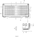
- FIG. 2 is a longitudinal cross-sectional view illustrating a state in which a distal end 26 of an upper can 20 is bent downward from a first flat portion 11 of a lower can 10 to couple the upper can 20 to the lower can 10 according to a first embodiment of the present invention.
- an electrode assembly 1 has a structure in which a separator, a negative electrode, a separator, and a positive electrode are sequentially put to be wound around a rotating core, and then a center pin 2 is inserted when the core is removed and also has a structure in which a positive electrode tab (not shown) extending from the positive electrode protrudes from one surface (a top surface in the drawing), and a negative electrode tab (not shown) extending from the negative electrode protrudes from the other surface (a bottom surface in the drawing). Also, before being completely inserted into the lower can 10, the negative electrode tab is bonded to the lower can 10, and the positive electrode tab is bonded to the upper can 20.
- the lower can 10 has a structure in which a first sidewall 11 is formed vertically upward along a circumference of the first flat portion 11 having a circular plate shape.
- the upper can 20 has a second sidewall 22 formed in a vertical direction along a circumference of the second flat portion 21 having a circular plate shape.
- a diameter of the second flat portion 21 is slightly larger than that of the first flat portion 11, and thus, the first sidewall 12 may be inserted into the second sidewall 22.
- the second flat portion 21 may face the first flat portion 11, and the second sidewall portion 22 may be coupled in a state of being placed outside the first sidewall portion 12.
- the upper can 20 and the lower can 10 may be coupled to each other in a state in which a gasket 30 is inserted between the first sidewall 12 and the second sidewall 22, which corresponds to a point at which the upper can 20 and the lower can 10 are in contact with each other, so as to prevent short circuit from occurring.
- the gasket 30 has a sufficient length so that an end of the first sidewall 12 and the second flat portion 21 do not come into contact with each other, and one end of the gasket 30 is placed inside the first sidewall 12.
- the second sidewall 22 has a distal end 26 that is bent to surround an edge, at which the first flat portion 11 and the first sidewall 12 are connected, and is placed below the first flat portion 11.
- the gasket 30 extends to be disposed between the distal end 26 and the first flat portion 11. Furthermore, the other end of the gasket 30 forms an exposed portion 31 protruding to the outside through the distal end 26.
- the separation of the lower can 10 may be strongly prevented compared to the conventional structure in which the upper can 20 and the lower can 10 are coupled to each other by press-fitting force therebetween.
- the second sidewall 22 comprises a body portion 23 bent from the second flat portion 21 and an expansion portion 25 connecting the body portion 23 to the distal end 26 and expanded in diameter rather than the body portion 23.
- an inclined portion 24 having an inclined cross-sectional shape is formed between the body portion 23 and the expansion portion 25 so as to be gradually expanded in diameter.
- the lower can 10 when the lower can 10 is inserted into the upper can 20 before the distal end 26 is bent, the lower can 10 may be easily inserted, and also, since the gasket 30 is more pressed at an end-side (an upper side in the drawing) of the first sidewall 12, which is close to the inside of the lower can 10, sealing force may increase.
- connection point between the expansion portion 25 and the distal end 26 may be curved at a predetermined curvature to prevent damage from occurring due to sharpness or a device, on which the secondary battery is mounted, from being scratched.
- FIG. 3 is a longitudinal cross-sectional view illustrating a state in which an exposed portion 31 increases in thickness to form a flat surface together with a distal end 26 according to a second embodiment of the present invention
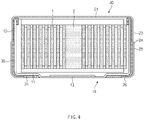
- FIG. 4 is a longitudinal cross-sectional view illustrating a state in which the exposed portion 31 increases in thickness and length to form a continuous flat surface between a protrusion 13 and the distal end 26.
- the exposed portion 31 of the gasket 30 protruding from the distal end 26 has a thickness D capable of forming a flat surface extending from the distal end 26.
- a protrusion 13 convexly protruding downward to have the same height as the distal end 26 protrudes from the first flat portion 11 of the lower can 10.
- the protrusion 13 is provided as a structure that protrudes to be in contact with a negative terminal of an external device to offset the portion protruding as described above.
- the exposed portion 31 has a thickness capable of forming the flat surface even with the protrusion 13, the protrusion 13, the exposed portion 31, and the distal end 26 may form a flat bottom surface in the button-type secondary battery.
- the flat surface may be discontinuously formed as illustrated in FIG. 3 or may be continuously formed as illustrated in FIG. 4 according to the length of the exposed portion 31.
- short circuit between the distal end 26 and the lower can 10 may be more effectively suppressed.
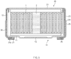
- FIG. 5 is a longitudinal cross-sectional view illustrating a state in which an exposed portion 31 is expanded downward from a distal end 26 to have a bent shape so as to cover a portion of a bottom surface of the distal end 26 according to a third embodiment of the present invention.
- the exposed portion 31 has a bent structure so that an end 31a of the exposed portion 31 is expanded downward from a distal end 26 to cover a portion of a bottom surface of the distal portion 26.
- the distal end 26 and a lower can 10 may be more reliably disconnected to fundamentally prevent short circuit from occurring.
- a gasket 30 having elasticity and insulating electricity is disposed at the uppermost end, when the secondary battery is stacked and seated, a surface of the secondary battery may be more efficiently prevented from being scratched, and when a plurality of secondary batteries are stacked in a longitudinal direction, electrical connection therebetween may be blocked.
- the distal end 26 formed on an end of the second sidewall 22 of the upper can 20 may be bent to surround an edge connecting a first flat portion 11 to a first sidewall 12 and be disposed below the first flat portion 11 to increase in coupling force between the upper can 20 and the lower can 10 compared to the conventional structure.
- the exposed portion 31 disposed below the first flat portion 11 through the distal end 26 to protrude to the outside may be formed on an end of the gasket 30 to more reliably prevent the electric short circuit from occurring between the upper can 20 and the lower can 10.
- the exposed portion 31 forms a flat surface together with the distal end 26, the possibility of occurrence of the unintentional short circuit by the metal object may be more reduced.
- the exposed portion 31 is expanded downward from the distal end 26 and is bent to cover a portion of the bottom surface of the distal end 26, the possibility of occurrence of the short circuit may be more reduced, and thus, the distal end 26 may be protected against a physical impact.
Landscapes
- Chemical & Material Sciences (AREA)
- Chemical Kinetics & Catalysis (AREA)
- Electrochemistry (AREA)
- General Chemical & Material Sciences (AREA)
- Engineering & Computer Science (AREA)
- Manufacturing & Machinery (AREA)
- Sealing Battery Cases Or Jackets (AREA)
- Connection Of Batteries Or Terminals (AREA)
- Secondary Cells (AREA)
Applications Claiming Priority (2)
| Application Number | Priority Date | Filing Date | Title |
|---|---|---|---|
| KR1020200087139A KR20220008685A (ko) | 2020-07-14 | 2020-07-14 | 버튼형 이차전지 |
| PCT/KR2021/009060 WO2022015058A1 (fr) | 2020-07-14 | 2021-07-14 | Batterie secondaire du type bouton |
Publications (2)
| Publication Number | Publication Date |
|---|---|
| EP4087033A1 true EP4087033A1 (fr) | 2022-11-09 |
| EP4087033A4 EP4087033A4 (fr) | 2024-01-17 |
Family
ID=79555678
Family Applications (1)
| Application Number | Title | Priority Date | Filing Date |
|---|---|---|---|
| EP21842476.0A Pending EP4087033A4 (fr) | 2020-07-14 | 2021-07-14 | Batterie secondaire du type bouton |
Country Status (6)
| Country | Link |
|---|---|
| US (1) | US20230065592A1 (fr) |
| EP (1) | EP4087033A4 (fr) |
| JP (1) | JP2023510836A (fr) |
| KR (1) | KR20220008685A (fr) |
| CN (1) | CN115053385A (fr) |
| WO (1) | WO2022015058A1 (fr) |
Family Cites Families (12)
| Publication number | Priority date | Publication date | Assignee | Title |
|---|---|---|---|---|
| JP2003242941A (ja) * | 2002-02-19 | 2003-08-29 | Matsushita Electric Ind Co Ltd | コイン形電池 |
| US9153835B2 (en) * | 2009-02-09 | 2015-10-06 | Varta Microbattery Gmbh | Button cells and method for producing same |
| WO2014042417A1 (fr) * | 2012-09-11 | 2014-03-20 | 주식회사 루트제이드 | Logement de batterie secondaire pourvu d'une unité de renfort de fixation |
| JP6811003B2 (ja) * | 2014-11-19 | 2021-01-13 | セイコーインスツル株式会社 | 電気化学セル及び電気化学セルの製造方法 |
| EP3255714B1 (fr) * | 2016-06-07 | 2019-07-31 | VARTA Microbattery GmbH | Cellules electrochimiques a depot de lithium, procede de preparation de telles cellules et batterie les comprenant |
| CN107425145B (zh) * | 2017-06-20 | 2023-06-20 | 惠州亿纬锂能股份有限公司 | 一种钮扣式锂电芯密封结构及密封方法 |
| FI128151B (fi) | 2017-10-11 | 2019-11-15 | Build Care Oy | Polymeeridispersio ja menetelmä sen valmistamiseksi |
| CN207587785U (zh) * | 2017-11-10 | 2018-07-06 | 松栢投资有限公司 | 可充电电池 |
| KR102512119B1 (ko) * | 2018-08-16 | 2023-03-22 | 주식회사 엘지에너지솔루션 | 이차 전지 |
| WO2020053790A1 (fr) * | 2018-09-11 | 2020-03-19 | Energizer Brands, Llc | Batterie d'aide auditive à passe-fil fendu |
| CN111009625A (zh) * | 2019-12-30 | 2020-04-14 | 广东微电新能源有限公司 | 储能装置 |
| CN111370636A (zh) * | 2020-05-11 | 2020-07-03 | 福建南平延平区南孚新能源科技有限公司 | 一种无焊接痕迹纽扣电池的生产方法及所制得的纽扣电池 |
-
2020
- 2020-07-14 KR KR1020200087139A patent/KR20220008685A/ko active Search and Examination
-
2021
- 2021-07-14 JP JP2022542660A patent/JP2023510836A/ja active Pending
- 2021-07-14 EP EP21842476.0A patent/EP4087033A4/fr active Pending
- 2021-07-14 CN CN202180012614.XA patent/CN115053385A/zh active Pending
- 2021-07-14 US US17/799,096 patent/US20230065592A1/en active Pending
- 2021-07-14 WO PCT/KR2021/009060 patent/WO2022015058A1/fr unknown
Also Published As
| Publication number | Publication date |
|---|---|
| KR20220008685A (ko) | 2022-01-21 |
| EP4087033A4 (fr) | 2024-01-17 |
| WO2022015058A1 (fr) | 2022-01-20 |
| US20230065592A1 (en) | 2023-03-02 |
| CN115053385A (zh) | 2022-09-13 |
| JP2023510836A (ja) | 2023-03-15 |
Similar Documents
| Publication | Publication Date | Title |
|---|---|---|
| US8697272B2 (en) | Secondary battery having an insulating member | |
| KR100965684B1 (ko) | 전지 팩 | |
| US8765283B2 (en) | Conductive tab and battery pack having the same | |
| JP4537361B2 (ja) | 円筒型リチウムイオン二次電池 | |
| CN105609862B (zh) | 可再充电电池 | |
| JP2004146362A (ja) | キャップ組立体、これを具備した2次電池及び、キャップ組立体の製造方法 | |
| CN105938881B (zh) | 具有盖的可再充电电池 | |
| US8475950B2 (en) | Secondary battery | |
| CN102237545B (zh) | 可再充电电池 | |
| KR101040887B1 (ko) | 금속탭 및 이를 이용하는 이차전지 | |
| EP4087033A1 (fr) | Batterie secondaire du type bouton | |
| EP2860796A2 (fr) | Batterie rechargeable présentant une protrusion de court-circuit | |
| US20230223625A1 (en) | Button-type secondary battery | |
| CN104810485B (zh) | 电池组 | |
| KR101582953B1 (ko) | 홀더에 탈부착이 가능한 배터리 보호회로 패키지 및 배터리 보호회로 패키지가 탈부착이 가능할 수 있는 홀더, 이를 포함하는 배터리 팩 | |
| KR102164002B1 (ko) | 밴드 조립체 | |
| EP4195376A1 (fr) | Batterie secondaire de type bouton | |
| US20230079224A1 (en) | Secondary battery | |
| US20100330412A1 (en) | Secondary battery | |
| JP4829432B2 (ja) | 密閉型電池 | |
| US8663838B2 (en) | Cylindrical secondary battery including center pin having improved structure | |
| EP4084196A1 (fr) | Batterie secondaire de type bouton | |
| EP4071899A1 (fr) | Batterie secondaire de type bouton | |
| US9559342B2 (en) | Battery terminal cover | |
| JP2011009006A (ja) | 電池パック |
Legal Events
| Date | Code | Title | Description |
|---|---|---|---|
| STAA | Information on the status of an ep patent application or granted ep patent |
Free format text: STATUS: THE INTERNATIONAL PUBLICATION HAS BEEN MADE |
|
| PUAI | Public reference made under article 153(3) epc to a published international application that has entered the european phase |
Free format text: ORIGINAL CODE: 0009012 |
|
| STAA | Information on the status of an ep patent application or granted ep patent |
Free format text: STATUS: REQUEST FOR EXAMINATION WAS MADE |
|
| 17P | Request for examination filed |
Effective date: 20220805 |
|
| AK | Designated contracting states |
Kind code of ref document: A1 Designated state(s): AL AT BE BG CH CY CZ DE DK EE ES FI FR GB GR HR HU IE IS IT LI LT LU LV MC MK MT NL NO PL PT RO RS SE SI SK SM TR |
|
| DAV | Request for validation of the european patent (deleted) | ||
| DAX | Request for extension of the european patent (deleted) | ||
| A4 | Supplementary search report drawn up and despatched |
Effective date: 20231218 |
|
| RIC1 | Information provided on ipc code assigned before grant |
Ipc: H01M 10/04 20060101ALI20231212BHEP Ipc: H01M 50/109 20210101ALI20231212BHEP Ipc: H01M 50/153 20210101ALI20231212BHEP Ipc: H01M 50/183 20210101ALI20231212BHEP Ipc: H01M 50/166 20210101AFI20231212BHEP |