EP4086735A1 - Appareil de présentation haptique, appareil de reconnaissance, appareil de commande et procédé de présentation haptique - Google Patents
Appareil de présentation haptique, appareil de reconnaissance, appareil de commande et procédé de présentation haptique Download PDFInfo
- Publication number
- EP4086735A1 EP4086735A1 EP22174261.2A EP22174261A EP4086735A1 EP 4086735 A1 EP4086735 A1 EP 4086735A1 EP 22174261 A EP22174261 A EP 22174261A EP 4086735 A1 EP4086735 A1 EP 4086735A1
- Authority
- EP
- European Patent Office
- Prior art keywords
- actuator
- contact state
- user
- haptic
- presentation apparatus
- Prior art date
- Legal status (The legal status is an assumption and is not a legal conclusion. Google has not performed a legal analysis and makes no representation as to the accuracy of the status listed.)
- Withdrawn
Links
Images


Classifications
-
- G—PHYSICS
- G08—SIGNALLING
- G08B—SIGNALLING OR CALLING SYSTEMS; ORDER TELEGRAPHS; ALARM SYSTEMS
- G08B6/00—Tactile signalling systems, e.g. personal calling systems
-
- G—PHYSICS
- G01—MEASURING; TESTING
- G01C—MEASURING DISTANCES, LEVELS OR BEARINGS; SURVEYING; NAVIGATION; GYROSCOPIC INSTRUMENTS; PHOTOGRAMMETRY OR VIDEOGRAMMETRY
- G01C21/00—Navigation; Navigational instruments not provided for in groups G01C1/00 - G01C19/00
- G01C21/26—Navigation; Navigational instruments not provided for in groups G01C1/00 - G01C19/00 specially adapted for navigation in a road network
- G01C21/34—Route searching; Route guidance
- G01C21/36—Input/output arrangements for on-board computers
- G01C21/3626—Details of the output of route guidance instructions
- G01C21/3652—Guidance using non-audiovisual output, e.g. tactile, haptic or electric stimuli
-
- G—PHYSICS
- G06—COMPUTING; CALCULATING OR COUNTING
- G06F—ELECTRIC DIGITAL DATA PROCESSING
- G06F1/00—Details not covered by groups G06F3/00 - G06F13/00 and G06F21/00
- G06F1/26—Power supply means, e.g. regulation thereof
- G06F1/32—Means for saving power
- G06F1/3203—Power management, i.e. event-based initiation of a power-saving mode
- G06F1/3206—Monitoring of events, devices or parameters that trigger a change in power modality
- G06F1/3231—Monitoring the presence, absence or movement of users
-
- G—PHYSICS
- G06—COMPUTING; CALCULATING OR COUNTING
- G06F—ELECTRIC DIGITAL DATA PROCESSING
- G06F1/00—Details not covered by groups G06F3/00 - G06F13/00 and G06F21/00
- G06F1/26—Power supply means, e.g. regulation thereof
- G06F1/32—Means for saving power
- G06F1/3203—Power management, i.e. event-based initiation of a power-saving mode
- G06F1/3234—Power saving characterised by the action undertaken
- G06F1/325—Power saving in peripheral device
-
- G—PHYSICS
- G06—COMPUTING; CALCULATING OR COUNTING
- G06F—ELECTRIC DIGITAL DATA PROCESSING
- G06F3/00—Input arrangements for transferring data to be processed into a form capable of being handled by the computer; Output arrangements for transferring data from processing unit to output unit, e.g. interface arrangements
- G06F3/01—Input arrangements or combined input and output arrangements for interaction between user and computer
- G06F3/016—Input arrangements with force or tactile feedback as computer generated output to the user
Definitions
- the present technology relates to a technology of a haptic presentation apparatus that presents a force including a tactile sense to a user.
- Patent Literature 1 discloses a device that provides a realistic feeling of an object by transmitting a reaction force from a virtual object to a user in games or virtual reality experiences. For example, this device uses a pressure sensor and a myoelectric sensor to detect a strength with which the user grips the device and how fingers are tightened. This device improves reproducibility of a tactile haptic sense by using correction data indicating individual differences, that is generated from a comparison between an illusionary tactile haptic sense induction function and characteristics of the illusionary tactile haptic sense of each user (see, for example, paragraphs [0043] and [0071] in specification of Patent Literature 1).
- Patent Literature 2 discloses a technology of a cellular phone to which a game function that allows a user to swing a cellular phone like a maracas in accordance with a rhythm of a musical piece reproduced by the cellular phone, is added.
- a counter electromotive force is generated in the vibration motor.
- a CPU of the cellular phone detects the vibration given by the user by detecting that counter electromotive force (see, for example, paragraphs [0015] and [0019] in specification of Patent Literature 2).
- haptic presentation apparatus for example, in order to surely transmit haptic information to the user, there are situations where it is necessary to accurately detect a contact state of the user with respect to the apparatus.
- An object of the present disclosure is to provide a technology of a haptic presentation apparatus and the like with which a contact state of a user with respect to the apparatus can be detected accurately.
- a haptic presentation apparatus includes an actuator mechanism, a transmission mechanism, a detection unit, and a recognition unit.
- the transmission mechanism is configured to transmit haptic information to a user using a driving force caused by the actuator mechanism.
- the detection unit is configured to detect a load amount applied to the actuator mechanism.
- the recognition unit is configured to recognize a contact state of the user with respect to the transmission mechanism on a basis of the load amount detected by the detection unit.
- the contact state of the user with respect to the transmission mechanism is recognized on the basis of the load amount of the actuator mechanism that generates a driving force for presenting a force to the user, the contact state can be recognized accurately.
- the haptic presentation apparatus may further include a control unit configured to control drive of the actuator mechanism on a basis of the contact state recognized by the recognition unit.
- the haptic presentation apparatus can present different haptic information to the user in accordance with the contact state of the user.
- the actuator mechanism may include a plurality of actuators, and the control unit may be configured to selectively switch drive of the plurality of actuators in accordance with the contact state.
- the transmission mechanism may include a plurality of transmission units that function as movable portions respectively configuring a part of the plurality of actuators.
- At least one of the plurality of actuators may output a vibration having a frequency of 50 Hz or more and 400 Hz or less.
- the actuator mechanism may include one actuator, and the control unit may be configured to generate different driving states of the actuator in accordance with the contact state.
- the transmission mechanism may include a plurality of transmission units that are configured to respectively transmit haptic information corresponding to the different driving states.
- the control unit may be configured to control the drive of the actuator mechanism while as least one of the different driving states is a vibration having a frequency of 50 Hz or more and 400 Hz or less.
- the recognition unit may be configured to measure, as the load amount, a counter electromotive voltage, driving current, rotation speed, or temperature of the actuator mechanism.
- the contact state can be recognized accurately.
- the haptic presentation apparatus may further include a casing that accommodates the actuator mechanism, and the transmission mechanism may form at least a part of the casing.
- the actuator mechanism may include at least one of an eccentric motor, a linear resonant actuator, a piezoelectric actuator, and a magnetostrictive actuator.
- a recognition apparatus is a recognition apparatus for a haptic presentation apparatus including an actuator mechanism.
- the recognition apparatus includes a recognition unit configured to detect a load amount applied to the actuator mechanism and recognize, on a basis of the load amount, a contact state of a user with respect to a transmission mechanism configured to transmit haptic information to the user using a driving force caused by the actuator mechanism.
- a haptic presentation method executed by the haptic presentation apparatus includes transmitting, by the transmission mechanism, haptic information to a user using a driving force caused by the actuator mechanism.
- the detection unit By the detection unit, a load amount applied to the actuator mechanism is detected.
- the recognition unit a contact state of the user with respect to the transmission mechanism is recognized on a basis of the load amount detected by the detection unit.
- a haptic presentation apparatus includes a plurality of actuators and a control unit.
- the plurality of actuators are configured to respectively generate driving forces corresponding to different driving states.
- the control unit is configured to recognize a contact state of a user with respect to the haptic presentation apparatus and selectively switch drive of the plurality of actuators in accordance with the recognized contact state.
- control unit selectively switching the actuator to be driven in accordance with the contact state of the user with respect to the haptic presentation apparatus, various types of haptic information based on a plurality of different driving states can be presented to the user.
- a control apparatus includes a control unit configured to recognize a contact state of a user with respect to a haptic presentation apparatus and selectively switch drive of a plurality of actuators that respectively generate driving forces corresponding to different driving states in accordance with the recognized contact state.
- a haptic presentation method for a haptic presentation apparatus includes recognizing, by a control unit of the haptic presentation apparatus including a plurality of actuators that respectively generate driving forces corresponding to different driving states, a contact state of a user with respect to the haptic presentation apparatus.
- control unit By the control unit, drive of the plurality of actuators is selectively switched in accordance with the recognized contact state.
- a contact state of a user with respect to an apparatus can be detected accurately.
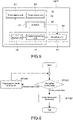
- FIG. 1 is a block diagram showing a configuration of a haptic presentation apparatus according to Configuration Example 1 of the present technology.
- a haptic presentation apparatus 100A is mainly applicable to portable electronic apparatuses such as a smartphone, a tablet terminal, an electronic book, and an electronic notebook, though is not necessarily limited to the portable type.
- the haptic presentation apparatus 100A can be used as a dedicated apparatus that presents haptic information.
- the haptic presentation apparatus 100A includes a haptic information output unit 10 and a detection unit 20.
- the haptic information output unit 10 mainly includes a central processing unit 12, a storage unit 14, an actuator mechanism 30, and a transmission mechanism 40.
- Hardware of the central processing unit 12 is constituted of a CPU (Central Processing Unit), an MPU (Micro Processing Unit), a PLD (Programmable Logic Device), or the like.
- the hardware of the central processing unit 12 may include a DSP (Digital Signal Processor) or the like.
- a program requisite for realizing the present technology is stored in the storage unit 14.
- the central processing unit 12 is configured to execute processing in cooperation with the program stored in the storage unit 14.
- the storage unit 14 is constituted of a well-known storage device such as a volatile and/or nonvolatile device.
- the central processing unit 12 and the storage unit 14 may be physically integrated.
- the actuator mechanism 30 includes, for example, one actuator 31.
- a driving state of the actuator 31 is controlled by the central processing unit 12.
- the driving state mainly refers to a driving force and its generation direction and corresponds to haptic information that is generated by the central processing unit 12 and output from the actuator mechanism 30.
- the driving state may include a driving time, a driving cycle, or the like in addition to the elements described above.
- the driving state refers to states of an amplitude, cycle, phase, and combination pattern of these for realizing the driving force and its generation direction.
- the "haptic sense” is mainly a force that a person receives from an object when touching the object (herein, haptic presentation apparatus 100A).
- the "haptic sense” also conceptually includes a “tactile sense” and also a concept of perceiving an illusional force as in a virtual haptic sense, an illusional haptic sense, and the like.
- a biased acceleration vibration to be described later can be used as means for realizing the illusional haptic sense.
- an electromagnetic actuator or a non-electromagnetic actuator can be used as the actuator mechanism 30 (actuator 31).
- the electromagnetic actuator is an actuator that uses an electromagnetic force as a driving force.
- Examples of the electromagnetic actuator include a rotary motor and a linear motor.
- the rotary motor includes, for example, an eccentric motor (ERM: Eccentric Rotating Motor).
- the linear motor includes, for example, a voice coil motor (VCM: Voice Coil Motor), a linear resonant actuator (LRA: Linear Resonant Actuator), and a magnetostrictive actuator.
- the non-electromagnetic actuator is an actuator other than the electromagnetic actuator.
- Examples of the non-electromagnetic actuator include a piezoelectric actuator, an actuator that uses a shape-memory alloy, and a polymer actuator.
- the transmission mechanism 40 includes, for example, one transmission unit 41.
- the transmission unit 41 is configured to transmit, using a driving force generated by the actuator 31, haptic information corresponding to that driving force (driving state) to the user.
- the transmission unit 41 is configured as a movable portion (mover) forming a part of the actuator 31.
- the movable portion is a weight.
- the transmission unit 41 may be constituted of at least a part of a casing of the haptic presentation apparatus 100A. In this case, elements of the actuator 31 other than the movable portion drive the transmission unit which is at least a part of the casing, by a movement of a center of gravity, an inertia force, and the like.
- the detection unit 20 is configured such that the central processing unit 12 detects information for recognizing a contact state of the user with respect to the haptic presentation apparatus 100A (e.g., casing).
- the haptic presentation apparatus 100A e.g., casing
- Examples of a detection amount to be detected by the detection unit 20 include a voltage, a current, a rotation speed, a pressure, a shear stress, an acceleration, an angular velocity, a position, a contact (contact position, contact force, or contact area), a magnetic field, an electric field, a humidity, a temperature, a light absorption amount, a light reflection amount, an image, and a sound pressure level (environmental sound etc.).
- the detection unit 20 only needs to include a sensor capable of detecting these parameters.
- the detection amount to be obtained by the detection unit 20 there is biological information of a user, for example.
- the biological information of the user include a magnetoencephalography, an electroencephalogram, a myoelectric voltage (or current), an electrocardiographic voltage (or current), a heart rate, and the like.
- a pulse wave, body temperature, and the like of the user may also be used as the biological information of the user.
- a casing (not shown) accommodates the central processing unit 12, the storage unit 14, and the actuator mechanism 30.
- the detection unit 20 may be accommodated in the casing, may be provided outside the casing, or both.
- the casing may be configured as a part of the actuator mechanism 30.
- the central processing unit 12 recognizes a contact state of the user with respect to the haptic presentation apparatus 100A (e.g., casing) on the basis of the information detected by the detection unit 20.
- the central processing unit 12, the storage unit 14, and the detection unit 20 function as a recognition unit 50 (recognition apparatus).
- the central processing unit 12 is configured to control drive of the actuator mechanism 30 on the basis of the recognized contact state of the user.
- the central processing unit 12 mainly functions as a control unit (control apparatus).
- Haptic presentation apparatuses 100B, 100C, 100D, and 100E according to Configuration Examples 2 to 5 to be described later also basically perform the operations described above.
- the central processing unit 12 can judge that the user is in contact with the haptic presentation apparatus 100A.
- the central processing unit 12 executes processing as follows.
- the central processing unit 12 judges that the user is in contact with the haptic presentation apparatus 100A in a case where a magnetoencephalography, electroencephalogram, myoelectric voltage (or current), electrocardiographic voltage (or current), heart rate, pulse wave, and/or body temperature are/is equal to or larger than a threshold value (or equal to or smaller than threshold value), are/is within a predetermined range, or have/has a predetermined cyclic pattern.
- Fig. 2 is a block diagram showing a configuration of a haptic presentation apparatus according to Configuration Example 2 of the present technology.
- elements including members, functions, and the like substantially similar to those of the haptic presentation apparatus 100A according to Configuration Example 1 above are denoted by the same symbols, descriptions thereof will be simplified or omitted, and different points will mainly be described.
- the detection unit 20 is configured to detect a load amount applied to the actuator mechanism 30.
- the detection unit 20 detects a counter electromotive voltage as a voltage or a driving current (in a case of constant voltage drive) as a current, to thus detect that load amount.
- the detection unit 20 can detect a rotation speed of the rotary motor using, for example, a Hall element or a rotary encoder.
- the detection unit 20 may detect a temperature of the actuator 31.
- the central processing unit 12 can calculate (convert) these counter electromotive voltage, driving current, rotation speed, or temperature as the load amount applied to the actuator mechanism 30.
- the detection unit 20 detects the load amount applied to the actuator 31 at this time, and the central processing unit 12 recognizes the contact state of the user with respect to the transmission unit 41 on the basis of the load amount detected by the detection unit 20.
- the central processing unit 12 can judge that the user is in contact with the haptic presentation apparatus 100B.
- an eccentric motor Eccentric Rotating Motor
- the eccentric motor causes the transmission unit 41 to vibrate, to thus present (transmit) a haptic sense
- a mass of an object connected to the movable portion of the actuator 31 increases, so a displacement amount of the center of gravity of the object is suppressed, and a vibration thereof is suppressed, with the result that the load is reduced, and a current value is lowered.
- a rotary motor is used as the actuator 31, and the rotary motor rotates the transmission unit 41 as a rotating body, to thus present (transmit) a haptic sense will be assumed.
- the load increases when the user touches the transmission unit 41, and the current value increases.
- the load amount increases or decreases even when objects other than the user come into contact, but in such a case, since the transmission unit 41 pushes that object away, the load fluctuates temporally irregularly. In contrast, in a case where the user intentionally touches the transmission unit 41, a hand or fingers follows/follow the transmission unit 41, so the load amount shows a regular pattern. Therefore, the contact state can be recognized by using an appropriate algorithm, machine learning, and the like.
- the haptic presentation apparatus 100B can adopt a driving method for the actuator 31 suited for recognizing a contact state.
- this is a dedicated actuator driving method for recognizing the contact state of the user. For example, by using a method of repeating drive and a measurement of a driving current (or counter electromotive voltage) for each vibration cycle, or the like, highly-accurate recognition can be made in a short time.
- the central processing unit 12 can detect a pushing degree of the user with respect to the transmission unit 41. Therefore, the contact state of the user can be recognized accurately. Further, in addition to this, by detecting pressure distribution information and the biological information of the user, the recognition accuracy is further improved.
- Fig. 3 is a block diagram showing a configuration of a haptic presentation apparatus according to Configuration Example 3 of the present technology.
- the actuator mechanism 30 of this haptic presentation apparatus 100C includes a plurality of actuators.
- the actuator mechanism 30 includes two actuators 31 and 32 that are connected to one transmission unit 41. There may be 3 or more actuators.
- the central processing unit 12 selectively switches drive by the plurality of actuators 31 and 32 in accordance with the recognized contact state of the user with respect to the haptic presentation apparatus 100C (e.g., casing). Specifically, the central processing unit 12 selects the actuator to be driven in accordance with the recognized contact state out of the actuators 31 and 32, and controls a driving state of the selected actuator. Accordingly, various types of haptic information based on a plurality of different driving states can be presented to the user.
- the central processing unit 12 can also control the driving states of the plurality of actuators 31 and 32 to be the same driving state simultaneously or non-simultaneously.
- the detection unit 20 may detect the load amount applied to the actuator mechanism 30 (at least one of plurality of actuators 31 and 32) as described in Configuration Example 2.
- a flow of information fed back from the actuator mechanism 30 to the detection unit 20 is indicated by an arrow in a broken line. The same holds true for Configuration Example 4 and subsequent embodiments below.
- the storage unit 14 only needs to store a relationship between the detection value obtained by the detection unit 20 and the load amount applied to the actuator mechanism 30 as a lookup table, for example. Alternatively, the storage unit 14 only needs to store an arithmetic expression that expresses the relationship between the detection value and the load amount.
- Fig. 4 is a block diagram showing a configuration of a haptic presentation apparatus according to Configuration Example 4 of the present technology.
- the transmission mechanism 40 of this haptic presentation apparatus 100D includes a plurality of transmission units 41 and 42, and the transmission units (41, 42) are respectively provided for the actuators (31, 32).
- the transmission unit 41 is connected to the actuator 31, and the transmission unit 42 is connected to the actuator 32.
- the actuator 31 transmits a driving force to the transmission unit 41, and the actuator 32 transmits a driving force to the transmission unit 42.
- 3 or more actuators and 3 or more transmission units may be provided.
- the central processing unit 12 selectively switches the drive by the plurality of actuators 31 and 32 in accordance with the contact state of the user with respect to the haptic presentation apparatus 100D (transmission unit 41 or casing). Specifically, the central processing unit 12 selects the actuator to be driven in accordance with the recognized contact state out of the plurality of actuators 31 and 32, and controls a driving state of the selected actuator. As a result, haptic information corresponding to that driving state is presented from the transmission unit connected to the selected actuator out of the transmission units 41 and 42. In Configuration Example 4, various types of haptic information based on a plurality of different driving states can be presented to the user as in Configuration Example 3.
- Fig. 5 is a block diagram showing a configuration of a haptic presentation apparatus according to Configuration Example 5 of the present technology.
- the actuator mechanism 30 of this haptic presentation apparatus 100E includes one actuator 31 that is connected to the plurality of (e.g., two) transmission units 41 and 42.
- the central processing unit 12 controls drive of the actuator 31 such that one actuator 31 transmits different haptic information to the transmission units 41 and 42 at different timings. Specifically, the central processing unit 12 controls the drive of the actuator 31 such that one actuator 31 generates different driving states in accordance with the contact state of the user with respect to the haptic presentation apparatus 100E (transmission unit 41 or casing).
- the haptic presentation apparatus 100E transmission unit 41 or casing.
- Configuration Example 5 various types of haptic information based on the driving states having different numbers can be presented to the user as in Configuration Examples 3 and 4.
- Fig. 6 is a flowchart showing, as Application Example 1, basic operations carried out by the haptic presentation apparatus 100C, 100D, or 100E according to Configuration Example 3, 4, or 5 out of Configuration Examples 1 to 5 described above.
- the central processing unit 12 detects the contact state of the user with respect to the haptic presentation apparatus (transmission unit 41 or casing) by the detection unit 20 (Step 101).
- the central processing unit 12 judges which of a first contact state and a second contact state the contact state is, and outputs first haptic information (Step 102) or outputs second haptic information different from the first haptic information (Step 103) in accordance with the judgment result.
- the central processing unit 12 presents haptic information corresponding to one of the different driving states using one or more actuators 31 in accordance with the contact state.
- the first contact state and the second contact state for example, there are a normal contact state (favorable contact state) and an abnormal contact state (unfavorable contact state).
- the abnormal contact state conceptually includes a non-contact state.
- the first haptic information is output in the first contact state
- the second haptic information is output in the second contact state.
- the distinction between the first contact state and the second contact state whether the user is gripping the haptic presentation apparatus in a predetermined way may be used.
- the central processing unit 12 may preset 3 or more contact states and output haptic information corresponding to 3 or more driving states in accordance with those 3 or more contact states. For example, the central processing unit 12 can judge the 3 contact states in a case where the detection values of the detection unit 20 are sorted to 3 or more ranges or patterns.
- the central processing unit 12 outputs haptic information that prompts the user to make a normal contact.
- the central processing unit 12 can cause the user to come into contact with the haptic presentation apparatus in a normal contact state, and accurately present haptic information to be output after that, to the user.
- the abnormal contact state there may be a case where the user is carrying the haptic presentation apparatus in a pocket of his/her clothes or in a bag. In this case, even if a driving force is generated in the transmission unit 41, the user may not be able to perceive it. Therefore, outputting the second haptic information accordingly is a typical purpose of the processing shown in Fig. 6 .
- a human perception sensitivity to vibrations of 50 Hz or more and 400 Hz or less is high.
- the actuator 31 is a vibration motor (e.g., eccentric motor, piezoelectric actuator, etc.)
- a driving state of the actuator 31 that causes a vibration of 50 Hz to 400 Hz can be used as the second haptic information.
- the central processing unit 12 may output third haptic information different from the first or second haptic information at a stage before recognizing the contact state of the user.
- this third haptic information is haptic information for executing the processing of recognizing the contact state of the user in Step 101.
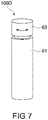
- Fig. 7 is a perspective view showing, as Application Example 2, a specific application example of the haptic presentation apparatus 100D according to Configuration Example 4 shown in Fig. 4 .
- the haptic presentation apparatus 100D includes a casing 61 and a rotating body 63.
- the casing 61 and the rotating body 63 each function as the transmission mechanism 40, that is, the transmission unit 41.
- the actuator mechanism 30 includes the actuator 31 that rotates the rotating body 63 and the actuator 32 that causes a grip portion to vibrate.
- a rotary motor is used as the actuator 31, for example.
- an ERM is used as the actuator 32.
- the user can grip the grip portion by his/her hand and touch the rotating body 63 with a finger (e.g., thumb).
- a finger e.g., thumb
- the finger moves in a right-hand direction along with a rightward rotation of the rotating body 63
- the finger moves in a left-hand direction along with a leftward rotation. Accordingly, the user can intuitively perceive the direction by making the rotation direction correspond to a guidance direction.
- Fig. 8 is a flowchart showing processing carried out by the haptic presentation apparatus 100D according to the Application Example 2. This flowchart shows processing of a walking navigation of the user using this haptic presentation apparatus 100D.
- the haptic presentation apparatus 100D or a portable apparatus (not shown) connectable to this haptic presentation apparatus 100D in a wired or wireless manner includes a global position sensor. Examples of a global position measurement system include a GPS (Global Positioning System), GLONASS (Global Navigation Satellite System), GNSS (Global Navigation Satellite System), and the like.
- the central processing unit 12 measures a distance between the current position of the haptic presentation apparatus 100D and the next guide point (Step 201). In a case where the user arrives at the destination, the central processing unit 12 presents information indicating the arrival (Step 202).
- the information indicating the arrival may be haptic information or information that uses images and audio.
- Step 203 the central processing unit 12 rotates the rotating body 63 by the actuator 31 and presents direction information by a haptic sense (Step 203).
- Step 203 the central processing unit 12 measures a driving current of the actuator 31 by the detection unit 20 (detects load amount) during the process of the rotation operation by the rotating body 63, and recognizes the contact state between the user and the rotating body 63 (Step 204).
- a driving current of the actuator 31 by the detection unit 20 (detects load amount) during the process of the rotation operation by the rotating body 63, and recognizes the contact state between the user and the rotating body 63 (Step 204).
- a counter electromotive voltage, a rotation speed of the rotating body 63, or a temperature of the actuator 31 may be used as the amount to be measured (amount to be detected).
- the central processing unit 12 stops the output of the actuator 31 after an elapse of a predetermined time (Step 207), and returns to the processing of Step 201.
- the central processing unit 12 judges that the contact state of the user is normal. In this normal contact state, a palm-side of the thumb of the user is in contact with the rotating body 63.
- Step 205 the central processing unit 12 stops the output of the actuator 31 and drives the actuator 32, to thus output vibrations for a certain period of time via the casing 61. In this way, the central processing unit 12 selectively switches the drive by the actuators 31 and 32 in accordance with the contact state of the user.
- Step 206 for example, a vibration of 50 Hz or more and 400 Hz or less, for example, a vibration of about 200 Hz, is output by the actuator 32 as described above.
- the central processing unit 12 repeats the processing of Steps 203 to 206 until a normal contact state of the user is obtained.
- the central processing unit 12 repeats the processing of Steps 203 to 206 until a normal contact state of the user is obtained.
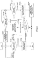
- Fig. 9 is a flowchart showing processing carried out by a haptic presentation apparatus according to Application Example 3. This processing mainly shows processing of a walking navigation of the user using the haptic presentation apparatus 100E according to Configuration Example 5 shown in Fig. 5 .
- a compact apparatus that can be grabbed by the user with a hand or pinched by fingers is used.
- Steps 301 and 302 are the same processing as Steps 201 and 202 shown in Fig. 8 .
- Step 303 in a case where the distance between the current position and the next guide point is smaller than the setting value, the central processing unit 12 outputs a biased acceleration vibration from the actuator 31 as haptic information.
- a biased acceleration vibration occurs in a translational movement of an inertial load (m).
- a difference is set between a maximum acceleration (a1) on an outward path and a maximum acceleration (a2) on a return path.
- a weak force e.g., m*a1
- a strong force e.g., m*a2
- Such a biased acceleration vibration is realized by one or a plurality of piezoelectric actuators, one or a plurality of LRAs, or a plurality of ERMs.
- Configuration Example 3 shown in Fig. 3 is used as the haptic presentation apparatus.
- a dedicated special actuator such as a pseudo haptic generation apparatus disclosed in WO 07/086426 may be used.
- a piezoelectric actuator or an LRA is favorable for miniaturizing the haptic presentation apparatus, raising energy use efficiency, and obtaining a desired vibration frequency.
- a biased acceleration vibration is caused in the entire casing (not shown) of the haptic presentation apparatus 100E.
- the haptic presentation apparatus 100E can present haptic information in a specific direction to the user as navigation information (Step 303).
- Step 304 the detection unit 20 measures a driving current (may be counter electromotive voltage etc.) of the actuator 31.
- the central processing unit 12 recognizes a contact state of the user on the basis of the measured driving current.
- Step 304 the central processing unit 12 judges whether a predetermined input from the user has been detected by the detection unit 20 (Step 309). In a case where it is judged that a predetermined input from the user has been detected, the central processing unit 12 stops the output of that biased acceleration vibration (Step 310).
- the processing of Steps 309 and 310 is carried out for the purpose of saving energy consumption of the haptic presentation apparatus or preventing the user from feeling uncomfortable in a case where the user notices the output of the haptic sense due to the biased acceleration vibration in Step 303, for example.
- an input of hard keys such as buttons, a touch on a touch panel, a pressure distribution change due to the user gripping the haptic presentation apparatus 100E, a load fluctuation or a fluctuation of an acceleration or the like due to a shake of the haptic presentation apparatus 100E, an audio input, or the like only needs to be used.
- the predetermined input from the user becomes a condition for stopping the biased acceleration vibration (Step 310).
- the following conditions may also be added as the condition for stopping the biased acceleration vibration.
- Examples of the conditions include an elapse of a certain time since a normal contact is judged in Step 304 (or after predetermined input of user is detected in Step 309), detecting a fact that a current path is a correct path, detecting that a guide point has passed, and the like.
- the central processing unit 12 stops the output of the biased acceleration vibration by the actuator 31 (Step 305). Then, the central processing unit 12 outputs a vibration by the actuator 31 (Step 306). Similar to Step 206 of Fig. 8 , the vibration herein is a vibration of 50 Hz or more and 400 Hz or less, which can be easily perceived by a person. The vibration of 200 Hz is more desirable.
- Step 307 the central processing unit 12 executes processing that is similar to that of Step 304 again (Step 307).
- the central processing unit 12 stops the output of the vibration by the actuator 31 (Step 308) and returns to the processing of Step 303.
- the central processing unit 12 generates different driving states of the actuator 31 in accordance with the contact state of the user.
- the processing carried out by the haptic presentation apparatus 100E according to Configuration Example 5 has been described in this Application Example 2.
- the haptic presentation apparatus 100C including, as the transmission mechanism 40, one transmission unit 41 instead of the plurality of transmission units 41, as in Configuration Example 3, may be used.
- the haptic presentation apparatus 100D including the plurality of actuators 31 and 32 as in Configuration Example 4 may be used.
- the haptic presentation apparatus can accurately recognize the contact state of the user, accurate haptic information based on that contact state can be presented to the user.
- the contact state can be recognized accurately, information can be surely transmitted by prompting the user to make a correct contact by vibrations or audio in a non-contact state (abnormal contact state).
- a non-contact state abnormal contact state
- the contact state can be recognized accurately, it is possible to reduce information transmission errors in which the user has not receive information while recognizing that the haptic presentation apparatus has transmitted the information.
- the contact state can be recognized accurately, it is possible to minimize a time for presenting a haptic sense, which requires large energy consumption.
- a vibration of 50 Hz or more and 400 Hz or less which is easy to be perceived, in the abnormal contact state, highly-efficient haptic information transmission becomes possible.
- power consumption can be additionally suppressed by switching to the actuator 31 that uses an LRA or the like having excellent energy efficiency.
- the haptic information is not limited to the periodic vibration and the biased acceleration vibration described above.
- an aperiodic impact an angular momentum change of a rotating body, a rotational movement, a translational movement, expansion and compression/contraction, a bending deformation movement, and the like may be used.
- the target of haptic information is not limited to the direction of the walking navigation described above.
- an alarm a time, a speed, a position, a shop, sightseeing, a sign, a language, an emotion, a status, information in a game, an eyesight, an auditory sense, and the like may be used.
- a gaming machine Besides the navigation apparatus described above, a gaming machine, a virtual reality environment generation apparatus, and the like may be used as the haptic presentation apparatus.
- At least two of the feature portions according to the present technology described above can be combined.
Applications Claiming Priority (3)
| Application Number | Priority Date | Filing Date | Title |
|---|---|---|---|
| JP2015237114 | 2015-12-04 | ||
| PCT/JP2016/004279 WO2017094211A1 (fr) | 2015-12-04 | 2016-09-20 | Dispositif de présentation de sentiment de force, dispositif de reconnaissance, dispositif de commande et procédé de présentation de sentiment de force |
| EP16870154.8A EP3385816A4 (fr) | 2015-12-04 | 2016-09-20 | Dispositif de présentation de sentiment de force, dispositif de reconnaissance, dispositif de commande et procédé de présentation de sentiment de force |
Related Parent Applications (1)
| Application Number | Title | Priority Date | Filing Date |
|---|---|---|---|
| EP16870154.8A Division EP3385816A4 (fr) | 2015-12-04 | 2016-09-20 | Dispositif de présentation de sentiment de force, dispositif de reconnaissance, dispositif de commande et procédé de présentation de sentiment de force |
Publications (1)
| Publication Number | Publication Date |
|---|---|
| EP4086735A1 true EP4086735A1 (fr) | 2022-11-09 |
Family
ID=58796679
Family Applications (2)
| Application Number | Title | Priority Date | Filing Date |
|---|---|---|---|
| EP16870154.8A Ceased EP3385816A4 (fr) | 2015-12-04 | 2016-09-20 | Dispositif de présentation de sentiment de force, dispositif de reconnaissance, dispositif de commande et procédé de présentation de sentiment de force |
| EP22174261.2A Withdrawn EP4086735A1 (fr) | 2015-12-04 | 2016-09-20 | Appareil de présentation haptique, appareil de reconnaissance, appareil de commande et procédé de présentation haptique |
Family Applications Before (1)
| Application Number | Title | Priority Date | Filing Date |
|---|---|---|---|
| EP16870154.8A Ceased EP3385816A4 (fr) | 2015-12-04 | 2016-09-20 | Dispositif de présentation de sentiment de force, dispositif de reconnaissance, dispositif de commande et procédé de présentation de sentiment de force |
Country Status (5)
| Country | Link |
|---|---|
| US (2) | US10395487B2 (fr) |
| EP (2) | EP3385816A4 (fr) |
| JP (1) | JP6787338B2 (fr) |
| CN (1) | CN108292169B (fr) |
| WO (1) | WO2017094211A1 (fr) |
Families Citing this family (6)
| Publication number | Priority date | Publication date | Assignee | Title |
|---|---|---|---|---|
| JP6969271B2 (ja) * | 2017-10-13 | 2021-11-24 | 富士通株式会社 | 触感提供装置、及び、触感提供方法 |
| US11175739B2 (en) * | 2018-01-26 | 2021-11-16 | Immersion Corporation | Method and device for performing actuator control based on an actuator model |
| JP7146425B2 (ja) * | 2018-03-19 | 2022-10-04 | ソニーグループ株式会社 | 情報処理装置、情報処理方法及び記録媒体 |
| CN109901066A (zh) * | 2018-12-31 | 2019-06-18 | 瑞声科技(新加坡)有限公司 | 马达系统辨识方法 |
| JP7286364B2 (ja) * | 2019-03-22 | 2023-06-05 | キヤノン株式会社 | 駆動制御装置、電子機器、駆動制御方法、およびプログラム |
| WO2022230330A1 (fr) * | 2021-04-26 | 2022-11-03 | ソニーグループ株式会社 | Dispositif de traitement d'informations, procédé de traitement d'informations, et programme |
Citations (6)
| Publication number | Priority date | Publication date | Assignee | Title |
|---|---|---|---|---|
| US6262712B1 (en) * | 1997-04-24 | 2001-07-17 | Microsoft Corporation | Handle sensor with fade-in |
| JP2001211239A (ja) | 2000-01-25 | 2001-08-03 | Yamaha Corp | 携帯電話機 |
| WO2007086426A1 (fr) | 2006-01-24 | 2007-08-02 | Nippon Telegraph And Telephone Corporation | Appareil generateur d’acceleration et appareil generateur de force pseudo tactile |
| US20090076723A1 (en) * | 2007-09-14 | 2009-03-19 | Palm, Inc. | Targeting Location Through Haptic Feedback Signals |
| US20120151339A1 (en) * | 2010-12-10 | 2012-06-14 | Microsoft Corporation | Accessing and interacting with information |
| JP2013145589A (ja) | 2007-09-14 | 2013-07-25 | National Institute Of Advanced Industrial & Technology | バーチャルリアリティ環境生成装置及びコントローラ装置 |
Family Cites Families (17)
| Publication number | Priority date | Publication date | Assignee | Title |
|---|---|---|---|---|
| US8020095B2 (en) * | 1997-11-14 | 2011-09-13 | Immersion Corporation | Force feedback system including multi-tasking graphical host environment |
| JP3987182B2 (ja) * | 1998-01-26 | 2007-10-03 | Idec株式会社 | 情報表示装置および操作入力装置 |
| JP2010257051A (ja) * | 2009-04-22 | 2010-11-11 | Funai Electric Co Ltd | 回転式入力装置及び電子機器 |
| CN102460935B (zh) * | 2009-06-05 | 2015-01-07 | 株式会社尼康 | 压电促动器、透镜镜筒及照相机 |
| KR20120042879A (ko) * | 2009-07-29 | 2012-05-03 | 교세라 가부시키가이샤 | 입력장치, 입력장치의 제어방법, 촉감제공장치 및 촉감제공장치의 제어방법 |
| JP5847407B2 (ja) * | 2010-03-16 | 2016-01-20 | イマージョン コーポレーションImmersion Corporation | プレタッチ及びトゥルータッチのためのシステム及び方法 |
| US8698766B2 (en) * | 2010-04-22 | 2014-04-15 | Maxim Integrated Products, Inc. | System integration of tactile feedback and touchscreen controller for near-zero latency haptics playout |
| JP5529663B2 (ja) * | 2010-07-28 | 2014-06-25 | 京セラ株式会社 | 入力装置 |
| WO2012067370A2 (fr) * | 2010-11-19 | 2012-05-24 | (주)하이소닉 | Module haptique utilisant un élément piézoélectrique |
| FR2978846B1 (fr) * | 2011-08-03 | 2013-09-13 | Dav | Module d'interface tactile |
| US8723824B2 (en) * | 2011-09-27 | 2014-05-13 | Apple Inc. | Electronic devices with sidewall displays |
| JP2013164771A (ja) * | 2012-02-13 | 2013-08-22 | Tokai Rika Co Ltd | 触覚呈示装置 |
| CN104395866B (zh) * | 2012-11-30 | 2018-02-23 | 松下知识产权经营株式会社 | 触觉提示装置及触觉提示方法 |
| JP2015128367A (ja) * | 2013-11-27 | 2015-07-09 | キヤノン株式会社 | 振動型アクチュエータの駆動装置、フォーカスレンズ駆動装置、及び撮像装置 |
| JP6190751B2 (ja) | 2014-04-11 | 2017-08-30 | 株式会社Soken | タッチパネル式入力装置 |
| US10379222B2 (en) * | 2014-07-04 | 2019-08-13 | Z-Senz Llc | Systems, devices, and/or methods for resonant light ranging and distance sensing |
| WO2016052582A1 (fr) * | 2014-09-30 | 2016-04-07 | 太陽誘電株式会社 | Dispositif électronique |
-
2016
- 2016-09-20 EP EP16870154.8A patent/EP3385816A4/fr not_active Ceased
- 2016-09-20 EP EP22174261.2A patent/EP4086735A1/fr not_active Withdrawn
- 2016-09-20 US US15/778,660 patent/US10395487B2/en active Active
- 2016-09-20 CN CN201680069518.8A patent/CN108292169B/zh active Active
- 2016-09-20 WO PCT/JP2016/004279 patent/WO2017094211A1/fr active Application Filing
- 2016-09-20 JP JP2017553602A patent/JP6787338B2/ja active Active
-
2019
- 2019-07-16 US US16/513,308 patent/US10614679B2/en active Active
Patent Citations (6)
| Publication number | Priority date | Publication date | Assignee | Title |
|---|---|---|---|---|
| US6262712B1 (en) * | 1997-04-24 | 2001-07-17 | Microsoft Corporation | Handle sensor with fade-in |
| JP2001211239A (ja) | 2000-01-25 | 2001-08-03 | Yamaha Corp | 携帯電話機 |
| WO2007086426A1 (fr) | 2006-01-24 | 2007-08-02 | Nippon Telegraph And Telephone Corporation | Appareil generateur d’acceleration et appareil generateur de force pseudo tactile |
| US20090076723A1 (en) * | 2007-09-14 | 2009-03-19 | Palm, Inc. | Targeting Location Through Haptic Feedback Signals |
| JP2013145589A (ja) | 2007-09-14 | 2013-07-25 | National Institute Of Advanced Industrial & Technology | バーチャルリアリティ環境生成装置及びコントローラ装置 |
| US20120151339A1 (en) * | 2010-12-10 | 2012-06-14 | Microsoft Corporation | Accessing and interacting with information |
Also Published As
| Publication number | Publication date |
|---|---|
| WO2017094211A1 (fr) | 2017-06-08 |
| JP6787338B2 (ja) | 2020-11-18 |
| EP3385816A4 (fr) | 2018-12-12 |
| CN108292169B (zh) | 2022-04-05 |
| US20190005781A1 (en) | 2019-01-03 |
| CN108292169A (zh) | 2018-07-17 |
| US10614679B2 (en) | 2020-04-07 |
| US10395487B2 (en) | 2019-08-27 |
| EP3385816A1 (fr) | 2018-10-10 |
| JPWO2017094211A1 (ja) | 2018-09-20 |
| US20190340898A1 (en) | 2019-11-07 |
Similar Documents
| Publication | Publication Date | Title |
|---|---|---|
| US10614679B2 (en) | Haptic presentation apparatus, recognition apparatus, control apparatus, and haptic presentation method | |
| US10007344B2 (en) | Electronic device including closed-loop controller for haptic actuator and related methods | |
| EP2502215B1 (fr) | Systèmes et procédés pour accroître la largeur de bande haptique dans un dispositif électronique | |
| CN103324305B (zh) | 偏心旋转质量致动器的触觉效应优化 | |
| KR101478936B1 (ko) | 디스플레이 수단들의 연속적인 움직임을 획득하는 방법 및 디바이스 | |
| KR101665144B1 (ko) | 공진 검출 시스템 및 방법 | |
| JP4379214B2 (ja) | 携帯端末装置 | |
| EP2975497A1 (fr) | Dispositif terminal, procédé de commande de dispositif terminal, et programme | |
| KR102366769B1 (ko) | 텍스처 시뮬레이션을 위한 햅틱 피드백을 갖는 스타일러스 | |
| US11150731B2 (en) | Multi-modal haptic feedback for an electronic device using a single haptic actuator | |
| EP3096206A1 (fr) | Effets haptiques basés sur un contact prédit | |
| CN107797659B (zh) | 含基于感测位置驱动的触觉致动器的电子设备和相关方法 | |
| JP2020013549A (ja) | 動的システム識別に基づく適応触覚効果レンダリング | |
| JP2003015810A (ja) | 手袋型入力装置 | |
| JP2007336513A (ja) | 叩きコマンド処理システム、及び、携帯機器の操作システム、並びに、携帯機器 | |
| KR101458192B1 (ko) | 햅틱 피드백 생성 장치, 방법 및 컴퓨터 판독 가능한 기록 매체 | |
| CN103631374A (zh) | 输入装置、输入系统、电子装置和感觉呈现方法 | |
| JP2008246179A (ja) | 活動量計 | |
| US11645896B2 (en) | Systems, devices, and methods for providing actuator braking | |
| WO2019043787A1 (fr) | Dispositif de commande de vibration | |
| KR20120130471A (ko) | 잔여 진동 제어 장치 |
Legal Events
| Date | Code | Title | Description |
|---|---|---|---|
| PUAI | Public reference made under article 153(3) epc to a published international application that has entered the european phase |
Free format text: ORIGINAL CODE: 0009012 |
|
| STAA | Information on the status of an ep patent application or granted ep patent |
Free format text: STATUS: REQUEST FOR EXAMINATION WAS MADE |
|
| 17P | Request for examination filed |
Effective date: 20220609 |
|
| AC | Divisional application: reference to earlier application |
Ref document number: 3385816 Country of ref document: EP Kind code of ref document: P |
|
| AK | Designated contracting states |
Kind code of ref document: A1 Designated state(s): AL AT BE BG CH CY CZ DE DK EE ES FI FR GB GR HR HU IE IS IT LI LT LU LV MC MK MT NL NO PL PT RO RS SE SI SK SM TR |
|
| STAA | Information on the status of an ep patent application or granted ep patent |
Free format text: STATUS: THE APPLICATION IS DEEMED TO BE WITHDRAWN |
|
| 18D | Application deemed to be withdrawn |
Effective date: 20230510 |