EP4086589A1 - Sensorgehäuse - Google Patents
Sensorgehäuse Download PDFInfo
- Publication number
- EP4086589A1 EP4086589A1 EP22000117.6A EP22000117A EP4086589A1 EP 4086589 A1 EP4086589 A1 EP 4086589A1 EP 22000117 A EP22000117 A EP 22000117A EP 4086589 A1 EP4086589 A1 EP 4086589A1
- Authority
- EP
- European Patent Office
- Prior art keywords
- plug
- sensor
- contact
- connection
- space
- Prior art date
- Legal status (The legal status is an assumption and is not a legal conclusion. Google has not performed a legal analysis and makes no representation as to the accuracy of the status listed.)
- Granted
Links
Images
Classifications
-
- G—PHYSICS
- G01—MEASURING; TESTING
- G01D—MEASURING NOT SPECIALLY ADAPTED FOR A SPECIFIC VARIABLE; ARRANGEMENTS FOR MEASURING TWO OR MORE VARIABLES NOT COVERED IN A SINGLE OTHER SUBCLASS; TARIFF METERING APPARATUS; MEASURING OR TESTING NOT OTHERWISE PROVIDED FOR
- G01D11/00—Component parts of measuring arrangements not specially adapted for a specific variable
- G01D11/24—Housings ; Casings for instruments
- G01D11/245—Housings for sensors
-
- H—ELECTRICITY
- H03—ELECTRONIC CIRCUITRY
- H03K—PULSE TECHNIQUE
- H03K17/00—Electronic switching or gating, i.e. not by contact-making and –breaking
- H03K17/94—Electronic switching or gating, i.e. not by contact-making and –breaking characterised by the way in which the control signals are generated
- H03K17/945—Proximity switches
- H03K17/95—Proximity switches using a magnetic detector
- H03K17/9505—Constructional details
-
- H—ELECTRICITY
- H03—ELECTRONIC CIRCUITRY
- H03K—PULSE TECHNIQUE
- H03K17/00—Electronic switching or gating, i.e. not by contact-making and –breaking
- H03K17/94—Electronic switching or gating, i.e. not by contact-making and –breaking characterised by the way in which the control signals are generated
- H03K17/945—Proximity switches
- H03K2017/9455—Proximity switches constructional details
Definitions
- the invention relates to a sensor housing according to the preamble of patent claim 1.
- a generic sensor housing with a measuring head part and a connection part constructed from a lower part and an upper part is from DE 28 19 782 A1 known.
- a socket part with sockets is arranged in the lower part as a terminal connection block.
- This socket part has cable entry channels on its underside, via which a connecting cable routed through the cable opening is electrically connected to the sockets.
- the upper part has an evaluation device part, which is connected to the socket part via plugs inserted into the sockets.
- the measuring head part is electrically connected to contact pins 21 via connecting lines, as a result of which an electrical contact is made with the evaluation device part.
- a typical design of sensors such as inductive or capacitive proximity sensors, includes a two-part housing.
- the sensor is arranged in a head part and a contacting device, e.g. a terminal block, for connecting a cable coming from the outside is arranged in a connection part.
- a contacting device e.g. a terminal block
- the connection part or the space enclosed by the connection part is therefore often also referred to as a terminal space.
- the sensor in the head part is connected to the contacting device by electrical lines, for which purpose the head part and the connection part have corresponding through-openings.
- connection part of the inductive proximity sensor NBB20-U1-UU or the capacitive sensor CJ15+U1+A2 from Pepperl + Fuchs GmbH is made up of two parts, for example a cover and a base, wherein the cover is connected to the head part, electrical lines are routed from a sensor in the head part into the cover and are in electrical operative connection with contact pins arranged in the cover.
- the terminal connection block is arranged in the lower part and has, on the one hand, sockets for the contact pins and, on the other hand, terminals for lines coming from the outside.
- the standard design of the IQ40 series from SICK AG e.g. the inductive proximity sensor IQ40-NPPKKOS, has a similar structure.
- contact pins in particular a plurality of contact pins, greatly restrict the direction from which the cover and base can be joined together.
- a balance must be struck between the reliability of the contact and the smooth running of the connection between the cover and base.
- the object of the invention is to specify a device that develops the prior art.
- a sensor housing is to be provided with a simple, intuitively accessible mechanism that can be operated without tools for the connection between the cover and the lower part of the connection part.
- a sensor housing comprising a head part with a sensor space for accommodating a sensor and a connection part adjoining the head part with a terminal space for accommodating a terminal connection block.
- the head part In a rear wall adjoining the connection part, the head part has a through-opening for the cable and/or connector to be fed through into the sensor space.
- connection part is connected to the head part by means of a connecting means.
- the connecting part has a first side wall adjoining the rear wall of the head part with a through opening at least overlapping the through opening of the head part for cable and/or plug feedthrough from the sensor space into the terminal space.
- connection part has a second side wall with an entry opening for the cable and/or plug feedthrough into the clamping space.
- a plug-in connection part is arranged in the terminal space, with which an electrical connection can be established between the sensor arranged in the head part and the terminal connection block.
- the connector part has a base body made of an electrically insulating material, at least two contact means made of an electrically conductive material for making electrical contact with the sensor, and at least two contact surfaces made of an electrically conductive material for connection to the terminal block.
- the contact means are designed as contact pins or as contact sockets of a plug-in connection for establishing an active electrical connection with a plug-in connection counterpart of the sensor.
- At least two contact means are each electrically connected to a contact surface, the contact surfaces being arranged spaced apart from one another on a first side surface of the base body and the first side surface of the base body being designed as a flat surface.
- the plug-in connection part represents an electrical connection part with two interfaces in order to create an electrical connection between a sensor arranged in the head part and a terminal block arranged in the connection part.
- the contact means form an interface for making electrical contact with the sensor, and the contact surfaces form an interface for connection to a terminal block.
- the base body is designed in one piece or in several pieces and consists of a single material or several different materials, e.g. one or several plastics.
- the design of the first side surface of the base body as a flat or planar surface enables a particularly high degree of freedom with regard to a direction of movement for approaching a counterpart for establishing a contact/an active electrical connection.
- the terminal connection block is introduced or arranged as a separate component in the terminal space, or the terminal connection block is formed in one piece with the connection part or a part of the connection part.
- the two interfaces are adapted or can be adapted to the respective requirements.
- the interfaces can be designed in accordance with known norms and/or standards.
- the contact means form, for example, together with the base body, a standardized male or female connector, e.g. a female, four-pin M 12 circular connector.
- the sensor can thus be connected to the plug-in connection part in a simple manner by means of a corresponding plug-in connection counterpart, for example a male circular plug-in connector, for which purpose the plug-in connection counterpart at least protrudes through the through-openings in the head part and the connection part into the clamping space.
- a corresponding plug-in connection counterpart for example a male circular plug-in connector, for which purpose the plug-in connection counterpart at least protrudes through the through-openings in the head part and the connection part into the clamping space.
- the second interface is formed by the contact surfaces arranged on a side surface of the base body. This provides a particularly simple interface whose tolerance with regard to alignment/positioning can be designed in a simple manner by the dimensions and the arrangement of the contact surfaces.
- the contact surfaces allow a great deal of freedom with regard to the direction from which the mating contacts are brought up.
- connection part In a two-part configuration of the connection part, in which contact between the contact surfaces and a terminal block is only achieved by joining the two parts together, the movement for the assembly is not further restricted by the contacting by means of contact surfaces.
- part of the base body with the contact means forms a female plug or a male plug.
- a male plug comprising the contact means or a female plug comprising the contact means is arranged on the base body.
- the contact areas each have a width of at least 1 mm or at least 2 mm.
- a length of the contact surfaces is preferably at least 1 mm or at least 2 mm or at least 5 mm or at least 1 cm.
- the size can be adapted to the available space and the type and arrangement of mating contacts.
- each contact means forms a one-piece molded part, e.g. a sheet metal molded part, with a contact surface and a connecting piece.
- the contact surfaces are thus positioned and held by joining the contact means to the base body. A particularly simple assembly of the plug connection part is made possible.
- the sensor housing has a holding device, arranged in the clamping space, for the plug-in connection part.
- the plug-in connection part is arranged with the contact means in the direction of the through-opening for cable and/or plug feedthrough into the sensor space and with the side surface comprising the contact surfaces in the direction of the input opening in the terminal space.
- the contact means of the connector part are arranged concentrically to the through-opening of the head part.
- the connecting part comprises a terminal space base and a terminal space cover, the terminal space base and the terminal space cover being assembled in a closing direction.
- terminal space cover and terminal space base merely designate two partial areas of the connection part that are matched to one another, without specifying a specific absolute position or alignment.
- the clamping space base includes the second side wall with the input opening.
- the clamping space cover includes the first side wall with the through-opening and is connected to the head part by means of the connecting means.
- the plug connection part is arranged in the clamping space cover.
- connection part A two-part configuration of the connection part is usual in order to allow access to the clamping space and, if necessary, to be able to change the orientation of the head part relative to the connection part.
- the lower part typically includes the terminal connection block, to which electrical lines routed from the outside through the input opening into the terminal space can be connected.
- terminal connection block can be arranged as a separate component in the lower part or can be designed in one piece with the lower part.
- the plug-in connection part By closing the connection part, i.e. placing the terminal space cover on the terminal space base, the plug-in connection part according to the invention creates an active electrical connection between the terminal block and an electrical connection part of the sensor, e.g. a plug.
- the sensor housing corresponds to the IP 68 standard or the IP 69K standard.
- an inductive or capacitive proximity sensor is provided, with the proximity sensor having a sensor housing of the type described above.
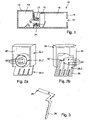
- FIG. 1 shows a cross section of a sensor housing 10 according to a first embodiment, comprising a head part 12 (hatched) with a sensor space 14 for receiving a sensor (not shown) and a connecting part 16 with a terminal space 18 for receiving a terminal block (not shown).
- a plug connection part 20 is arranged in the clamping space.
- the head part 12 is connected to the connection part 16 by means of a connection part 22 , the connection part 22 protruding through a through opening in a first side wall of the connection part 16 .
- the connecting part 22 has a through-opening 24 for cable and/or connector passage between the sensor space 14 and the terminal space 18 .
- the connecting part 16 has an entry opening 34 in a second side wall for the cable and/or connector to be fed through from the outside into the clamping space 18 .
- the plug connection part 20 is arranged in front of the through opening 24 of the connection part 22 .
- FIG. 2 a perspective view of the connector part 20 according to a first embodiment is shown from two viewing directions.
- the connector part 20 consists of a base body 26, four socket-shaped contact means 28 and four contact surfaces 30.
- the base body has a holding frame 26.1, a plug connection section 26.2 and a first side face 26.3.
- the holding frame 26.1 is designed in such a way that it can be positioned in a position in front of the through-opening 24 of the connecting part 22 of the head part 12 in a form-fitting manner in the clamping space 18 of the connecting part 16.
- the contact means 28 are arranged in the plug connection section 26.2.
- the first side surface 26.3 is arranged on a side of the plug-in connection part 20 facing away from the plug-in connection section 26.2 and is flat.
- the contact means 28 penetrate the plug-in connection section 26.2 and are connected on a rear side in each case by means of an electrically conductive connecting piece 32 to a contact surface 30 arranged on the first side surface 26.3.
- the contact means 28, the connecting pieces 32 and the contact surfaces 30 together form a one-piece molded part, as shown in FIG figure 3 is shown schematically.
Landscapes
- Physics & Mathematics (AREA)
- General Physics & Mathematics (AREA)
- Connector Housings Or Holding Contact Members (AREA)
- Details Of Connecting Devices For Male And Female Coupling (AREA)
Abstract
Description
- Die Erfindung betrifft ein Sensorgehäuse gemäß dem Oberbegriff des Patentanspruchs 1.
- Ein gattungsgemäßes Sensorgehäuse mit einem Messkopfteil und einem aus einem Unterteil und einem Oberteil aufgebauten Anschlussteil ist aus der
DE 28 19 782 A1 bekannt. In dem Unterteil ist als Klemmenanschlussblock ein Buchsenteil mit Buchsen angeordnet. Dieses Buchsenteil weist auf einer Unterseite Kabeleinführungskanäle auf, über die ein durch die Kabelöffnung geführtes Anschlusskabel mit den Buchsen elektrisch verbunden wird. Das Oberteil weist ein Auswertegeräteteil auf, welches über in die Buchsen eingeführte Stecker mit dem Buchsenteil verbunden wird. Das Messkopfteil wird über Anschlussleitungen mit Kontaktstiften 21 elektrisch verbunden, wodurch ein elektrischer Kontakt mit dem Auswertegeräteteil hergestellt wird. - Eine typische Bauform von Sensoren, wie induktiven oder kapazitativen Näherungssensoren, umfasst ein zweiteiliges Gehäuse. Der Sensor ist in einem Kopfteil angeordnet und in einem Anschlussteil wird eine Kontaktiervorrichtung, z.B. ein Klemmanschlussblock, zum Anschließen eines von außen kommenden Kabels angeordnet. Das Anschlussteil bzw. der von dem Anschlussteil umfasste Raum wird daher häufig auch als Klemmraum bezeichnet.
- Der Sensor in dem Kopfteil ist durch elektrische Leitungen mit der Kontaktiervorrichtung verbunden, wofür das Kopfteil und das Anschlussteil entsprechende Durchgangsöffnungen umfassen.
- Das Anschlussteil des induktiven Näherungssensors NBB20-U1-UU oder des kapazitiven Sensors CJ15+U1+A2 der Fa. Pepperl + Fuchs GmbH ist beispielsweise zweiteilig aus einem Deckel und einem Unterteil zusammengesetzt, wobei der Deckel mit dem Kopfteil verbunden ist, elektrische Leitungen von einem Sensor in dem Kopfteil in den Deckel geführt werden und in elektrischer Wirkverbindung mit in dem Deckel angeordneten Kontaktstiften stehen. Der Klemmanschlussblock ist in dem Unterteil angeordnet und weist einerseits Buchsen für die Kontaktstifte und andererseits Klemmen für von außen kommende Leitungen auf.
- Auch die Standardbauform der Baureihe IQ40 der Fa. SICK AG, z.B. der induktive Näherungssensor IQ40-NPPKKOS weist einen ähnlichen Aufbau auf.
- Nachteilig ist, dass durch Kontaktstifte, insbesondere mehrere Kontaktstifte, die Richtung sehr eingeschränkt wird, aus der Deckel und Unterteil zusammen gefügt werden können. Außerdem muss zwischen der Zuverlässigkeit der Kontaktierung und der Leichtgängigkeit der Verbindung von Deckel und Unterteil abgewogen werden.
- Je passgenauer und länger die Kontaktstifte sind, umso schwergängiger ist das Trennen oder Verbinden von Deckel und Unterteil.
- Vor diesem Hintergrund besteht die Aufgabe der Erfindung darin, eine Vorrichtung anzugeben, die den Stand der Technik weiterbildet. Insbesondere soll ein Sensorgehäuse mit einem einfachen, intuitiv zugänglichen und werkzeuglos bedienbaren Mechanismus für die Verbindung zwischen dem Deckel und Unterteil des Anschlussteils bereitgestellt werden.
- Die Aufgabe wird durch eine Vorrichtung mit den Merkmalen des Patentanspruchs 1 gelöst. Vorteilhafte Ausgestaltungen der Erfindung sind Gegenstand von Unteransprüchen.
- Gemäß dem Gegenstand der Erfindung wird ein Sensorgehäuse bereitgestellt, umfassend ein Kopfteil mit einem Sensorraum zur Aufnahme eines Sensors und ein an das Kopfteil angrenzendes Anschlussteil mit einem Klemmraum zur Aufnahme eines Klemmenanschlussblocks.
- Das Kopfteil weist in einer an das Anschlussteil angrenzenden Rückwand eine Durchgangsöffnung zur Kabel- und/oder Steckerdurchführung in den Sensorraum auf.
- Das Anschlussteil ist mittels eines Verbindungsmittels mit dem Kopfteil verbunden.
- Das Anschlussteil weist eine an die Rückwand des Kopfteils angrenzende erste Seitenwand mit einer mit der Durchgangsöffnung des Kopfteils zumindest überlappenden Durchgangsöffnung zur Kabel- und/oder Steckerdurchführung von dem Sensorraum in den Klemmraum auf.
- Außerdem weist das Anschlussteil eine zweite Seitenwand mit einer Eingangsöffnung zur Kabel- und/oder Steckerdurchführung in den Klemmraum auf.
- In dem Klemmraum ist ein Steckverbindungsteil angeordnet, mit welchem eine elektrische Verbindung zwischen dem in dem Kopfteil angeordneten Sensor und dem Klemmenanschlussblock herstellbar ist.
- Das Steckverbindungsteil weist einen aus einem elektrisch isolierenden Material bestehenden Grundkörper, mindestens zwei aus einem elektrisch leitfähigen Material bestehende Kontaktmittel zur elektrischen Kontaktierung des Sensors und mindestens zwei aus einem elektrisch leitfähigen Material bestehende Kontaktflächen zur Verbindung mit dem Klemmenanschlussblock auf.
- Die Kontaktmittel sind als Kontaktstifte oder als Kontaktbuchsen einer Steckverbindung zur Herstellung einer elektrischen Wirkverbindung mit einem Steckverbindungsgegenstück des Sensors ausgebildet.
- Mindestens zwei Kontaktmittel stehen jeweils mit einer Kontaktfläche in elektrischer Wirkverbindung, wobei die Kontaktflächen auf einer ersten Seitenfläche des Grundkörpers jeweils zueinander beabstandet angeordnet sind und die erste Seitenfläche des Grundkörpers als ebene Fläche ausgebildet ist. Das Steckverbindungsteil stellt ein elektrisches Verbindungteil mit zwei Schnittstellen dar, um eine elektrische Verbindung zwischen einem in dem Kopfteil angeordneten Sensor und einem in dem Anschlussteil angeordneten Klemmanschlussblock zu gestalten.
- Die Kontaktmittel bilden eine Schnittstelle zur elektrischen Kontaktierung des Sensors und die Kontaktflächen eine Schnittstelle zur Verbindung mit einem Klemmanschlussblock.
- Es versteht sich, dass der Grundkörper einstückig oder mehrstückig ausgebildet ist und aus einem einzigen oder mehreren unterschiedlichen Materialien, z.B. einem oder mehreren Kunststoffen, besteht. Die Ausbildung der ersten Seitenfläche des Grundkörpers als ebene bzw. plane Fläche ermöglicht eine besonders hohe Freiheit hinsichtlich einer Bewegungsrichtung zum Annähern eines Gegenstücks zum Herstellen eines Kontakts/einer elektrischen Wirkverbindung.
- Der Klemmenanschlussblock wird als separates Bauteil in den Klemmraum eingebracht bzw. angeordnet oder der Klemmenanschlussblock wird mit dem Anschlussteil oder einem Teil des Anschlussteils einstückig ausgebildet.
- Es versteht sich, auch, dass die beiden Schnittstellen an die jeweiligen Anforderungen angepasst sind bzw. angepasst werden können. Insbesondere können die Schnittstellen entsprechend bekannter Normen und/oder Standards ausgebildet sein.
- Die Kontaktmittel bilden beispielsweise zusammen mit dem Grundkörper einen standardisierten männlichen oder weiblichen Stecker, z.B. einen weiblichen, vier-poligen M 12 Rundsteckverbinder aus.
- Der Sensor kann so auf einfache Weise mittels eines entsprechenden Steckverbindungsgegenstücks, z.B. männlichen Rundsteckverbinders mit dem Steckverbindungsteil verbunden werden, wozu das Steckverbindungsgegenstück durch die Durchgangsöffnungen in dem Kopfteil und dem Anschlussteil in den Klemmraum zumindest hineinragt.
- Die zweite Schnittstelle wird durch die auf einer Seitenfläche des Grundkörpers angeordneten Kontaktflächen ausgebildet. Hierdurch wird eine besonders einfache Schnittstelle bereitgestellt, deren Toleranz hinsichtlich Ausrichtung/Positionierung auf einfache Weise durch die Dimensionen und die Anordnung der Kontaktflächen gestaltet werden kann.
- Darüber hinaus ermöglichen die Kontaktflächen eine große Freiheit hinsichtlich der Richtung aus der die Gegenkontakte herangeführt werden.
- Bei einer zweiteiligen Ausgestaltung des Anschlussteils, bei der ein Kontakt zwischen den Kontaktflächen und einem Klemmanschlussblock erst durch das Zusammenfügen der beiden Teile erreicht wird, wird die Bewegung für das Zusammenfügen durch die Kontaktierung mittels Kontaktflächen nicht weiter eingeschränkt.
- Gemäß einer ersten alternativen Ausführungsform bildet ein Teil des Grundkörpers mit den Kontaktmitteln einen weiblichen Stecker oder einen männlichen Stecker.
- In einer alternativen Ausführungsform ist an dem Grundkörper ein die Kontaktmittel umfassender männlicher Stecker oder eine die Kontaktmittel umfassender weiblicher Stecker angeordnet.
- In einer anderen Ausführungsform weisen die Kontaktflächen jeweils eine Breite von mindestens 1 mm oder mindestens 2 mm auf. Eine Länge der Kontaktflächen ist bevorzugt mindestens 1mm oder mindestens 2 mm oder mindestens 5 mm oder mindestens 1 cm.
- Die Größe kann insbesondere an den vorhandenen Platz und die Art und Anordnung von Gegenkontakten angepasst werden. Je größer die Kontaktflächen und die Abstände zwischen den Kontaktflächen gewählt werden, umso mehr Freiheiten ergeben sich hinsichtlich der Positionierung von Gegenkontakten.
- In einer weiteren Weiterbildung bildet jeweils ein Kontaktmittel mit einer Kontaktfläche und einem Verbindungsstück ein einstückiges Formteil, z.B. ein Blechformteil, aus. So werden die Kontaktflächen durch Fügen der Kontaktmittel mit dem Grundkörper positioniert und gehalten. Es wird eine besonders einfache Montage des Steckverbindungsteils ermöglicht.
- Gemäß einer anderen Weiterbildung weist das Sensorgehäuse eine in dem Klemmraum angeordnete Haltevorrichtung für das Steckverbindungsteil auf.
- In einer weiteren Ausführungsform ist das Steckverbindungsteil mit den Kontaktmitteln in Richtung der Durchgangsöffnung zur Kabel- und/oder Steckerdurchführung in den Sensorraum und mit der die Kontaktflächen umfassenden Seitenfläche in Richtung der Eingangsöffnung in dem Klemmraum angeordnet.
- Gemäß einer anderen Ausführungsform sind die Kontaktmittel des Steckverbindungsteils konzentrisch zu der Durchgangsöffnung des Kopfteils angeordnet.
- In einer weiteren Weiterbildung umfasst das Anschlussteil ein Klemmraumunterteil und einen Klemmraumdeckel, wobei das Klemmraumunterteil und der Klemmraumdeckel in einer Schließrichtung zusammengesetzt sind.
- Es versteht sich, dass die Begriffe Klemmraumdeckel und Klemmraumunterteil lediglich zwei aufeinander abgestimmte Teilbereiche des Anschlussteils bezeichnen, ohne eine bestimmte absolute Position oder Ausrichtung festzulegen.
- Das Klemmraumunterteil umfasst die zweite Seitenwand mit der Eingangsöffnung.
- Der Klemmraumdeckel umfasst die erste Seitenwand mit der Durchgangsöffnung und ist mittels des Verbindungsmittels mit dem Kopfteil verbunden.
- Das Steckverbindungsteil ist in dem Klemmraumdeckel angeordnet.
- Eine zweiteilige Ausgestaltung des Anschlussteils ist üblich, um einen Zugang zu dem Klemmraum zu ermöglichen und gegebenenfalls die Ausrichtung des Kopfteils relativ zu dem Anschlussteil ändern zu können.
- Das Unterteil umfasst typischerweise den Klemmenanschlussblock, an den von außen durch die Eingangsöffnung in den Klemmraum geführte elektrische Leitungen anschließbar sind.
- Es versteht sich, dass der Klemmenanschlussblock als separates Bauteil in dem Unterteil angeordnet oder einstückig mit dem Unterteil ausgebildet sein kann.
- Durch das Schließen des Anschlussteils, also dem Aufsetzen des Klemmraumdeckels auf das Klemmraumunterteil, stellt das erfindungsgemäße Steckverbindungsteil eine elektrische Wirkverbindung zwischen dem Klemmenanschlussblock und einem elektrischen Anschlussteil des Sensors, z.B. einem Stecker, her.
- In einer anderen Weiterbildung entspricht das Sensorgehäuse dem IP 68 Standard oder dem IP 69K Standard.
- In einer Weiterbildung wird ein induktiver oder kapazitiver Näherungssensor bereitgestellt, wobei der Näherungssensor ein Sensorgehäuse der vorbeschriebenen Art aufweist.
- Die Erfindung wird nachfolgend unter Bezugnahme auf die Zeichnungen näher erläutert. Hierbei werden gleichartige Teile mit identischen Bezeichnungen beschriftet. Die dargestellten Ausführungsformen sind stark schematisiert, d.h. die Abstände und die lateralen und die vertikalen Erstreckung ist nicht maßstäblich und weisen, sofern nicht anders angegeben, auch keine ableitbaren geometrischen Relationen zueinander auf. Darin zeigen, die
- Figur 1
- einen Querschnitt einer ersten erfindungsgemäßen Ausführungsform eines Sensorgehäuses mit einem Steckverbindungsteil,
- Figur 2
- eine perspektivische Ansicht eines Steckverbindungsteils gemäß einer ersten erfindungsgemäßen Ausführungsform,
- Figur 3
- eine perspektivische Ansicht eines die Kontaktmittel und Kontaktflächen umfassenden Formteils.
- Die Abbildung der
Figur 1 zeigt einen Querschnitt eines Sensorgehäuses 10 gemäß einer ersten Ausführungsform, umfassend ein Kopfteil 12 (schraffiert) mit einem Sensorraum 14 zur Aufnahme eines Sensors (nicht dargestellt) und ein Anschlussteil 16 mit einem Klemmraum 18 zur Aufnahme eines Klemmenanschlussblocks (nicht dargestellt). In dem Klemmraum ist ein Steckverbindungsteil 20 angeordnet. - Das Kopfteil 12 ist mittels eines Verbindungsteils 22 mit dem Anschlussteil 16 verbunden, wobei das Verbindungsteil 22 durch eine Durchgangsöffnung in einer ersten Seitenwand des Anschlussteils 16 hineinragt.
- Das Verbindungsteil 22 weist eine Durchgangsöffnung 24 zur Kabel- und/oder Steckerdurchführung zwischen dem Sensorraum 14 und dem Klemmraum 18 auf. Außerdem weist das Anschlussteil 16 in einer zweiten Seitenwand eine Eingangsöffnung 34 zur Kabel- und/oder Steckerdurchführung von außen in den Klemmraum 18 auf.
- Das Steckverbindungsteil 20 ist vor der Durchgangsöffnung 24 des Verbindungsteils 22 angeordnet.
- In der Abbildung der
Figur 2 ist eine perspektivische Ansicht des Steckverbindungsteils 20 gemäß einer ersten Ausführungsform aus zwei Blickrichtungen dargestellt. - Das Steckverbindungsteil 20 besteht aus einem Grundkörper 26, vier buchsenförmigen Kontaktmitteln 28 und vier Kontaktflächen 30.
- Der Grundkörper weist einen Halterahmen 26.1, einen Steckverbindungsabschnitt 26.2 und eine erste Seitenfläche 26.3 auf. Der Halterahmen 26.1 ist so ausgestaltet, dass er an einer Position vor der Durchgangsöffnung 24 des Verbindungsteils 22 des Kopfteils 12 formschlüssig in den Klemmraum 18 des Anschlussteils 16 positionierbar ist.
- In dem Steckverbindungsabschnitt 26.2 sind die Kontaktmittel 28 angeordnet. Die erste Seitenfläche 26.3 ist auf einer von dem Steckverbindungsabschnitt 26.2 abgewandten Seite des Steckverbindungsteils 20 angeordnet und eben ausgebildet.
- Die Kontaktmittel 28 durchdringen den Steckverbindungsabschnitt 26.2 und sind an einer Rückseite jeweils mittels eines elektrisch leitfähigen Verbindungstücks 32 mit einer auf der ersten Seitenfläche 26.3 angeordneten Kontaktfläche 30 verbunden.
- Die Kontaktmittel 28, die Verbindungsstücke 32 und die Kontaktflächen 30 bilden gemäß einer ersten Ausführungsform zusammen ein einstückiges Formteil aus, wie es in der Abbildung der
Figur 3 schematisch dargestellt ist.
Claims (12)
- Sensorgehäuse (10), umfassend ein Kopfteil (12) mit einem Sensorraum (14) zur Aufnahme eines Sensors und ein an das Kopfteil (12) angrenzendes Anschlussteil (16) mit einem Klemmraum (18) zur Aufnahme eines Klemmenanschlussblocks, wobei- das Kopfteil (12) in einer an das Anschlussteil (16) angrenzenden Rückwand eine Durchgangsöffnung (24) zur Kabel- und/oder Steckerdurchführung in den Sensorraum (14) aufweist,- das Anschlussteil (16) mittels eines Verbindungsmittels (22) mit dem Kopfteil (12) verbunden ist,- das Anschlussteil (16) eine an die Rückwand des Kopfteils (12) angrenzende erste Seitenwand mit einer mit der Durchgangsöffnung (24) des Kopfteils (12) zumindest überlappenden Durchgangsöffnung zur Kabel- und/oder Steckerdurchführung von dem Sensorraum (14) in den Klemmraum (18) aufweist und- das Anschlussteil (16) eine zweite Seitenwand mit einer Eingangsöffnung (34) zur Kabel- und/oder Steckerdurchführung in den Klemmraum (18) aufweist,
dadurch gekennzeichnet, dass- in dem Klemmraum (18) ein Steckverbindungsteil (20) angeordnet ist, mit welchem eine elektrische Verbindung zwischen dem in dem Kopfteil (12) angeordneten Sensor und dem Klemmenanschlussblock herstellbar ist,- das Steckverbindungsteil (20) einen aus einem elektrisch isolierenden Material bestehenden Grundkörper (26), mindestens zwei aus einem elektrisch leitfähigen Material bestehende Kontaktmittel (28) zur elektrischen Kontaktierung des Sensors und mindestens zwei aus einem elektrisch leitfähigen Material bestehende Kontaktflächen (30) zur Verbindung mit dem Klemmenanschlussblock aufweist,- die Kontaktmittel (28) als Kontaktstifte oder als Kontaktbuchsen einer Steckverbindung zur Herstellung einer elektrischen Wirkverbindung mit einem Steckverbindungsgegenstück des Sensors ausgebildet sind,- mindestens zwei Kontaktmittel (28) jeweils mit einer Kontaktfläche (30) in elektrischer Wirkverbindung stehen, und- die Kontaktflächen (30) auf einer ersten Seitenfläche (26.3) des Grundkörpers (20) jeweils zueinander beabstandet angeordnet sind, wobei die erste Seitenfläche (26.3) des Grundkörpers (26) als ebene Fläche ausgebildet ist. - Sensorgehäuse (10) nach Anspruch 1, dadurch gekennzeichnet, dass ein Teil des Grundkörpers (26) mit den Kontaktmitteln (28) einen weiblichen Stecker oder einen männlichen Stecker bildet.
- Sensorgehäuse (10) nach Anspruch 1, dadurch gekennzeichnet, dass an dem Grundkörper (26) ein die Kontaktmittel (28) umfassender männlicher Stecker oder eine die Kontaktmittel (28) umfassender weiblicher Stecker angeordnet ist.
- Sensorgehäuse (10) nach einem der vorangegangenen Ansprüche, dadurch gekennzeichnet, dass die Kontaktflächen (30) jeweils eine Breite von mindestens 1 mm oder mindestens 2 mm aufweisen.
- Sensorgehäuse (10) nach einem der vorangegangenen Ansprüche, dadurch gekennzeichnet, dass die Kontaktflächen (30) jeweils eine Länge von mindestens 1mm oder mindestens 2 mm oder mindestens 5 mm oder mindestens 1 cm aufweisen.
- Sensorgehäuse (10) nach einem der vorangegangenen Ansprüche, dadurch gekennzeichnet, dass jeweils eines der Kontaktmittel (28) mit einer der Kontaktflächen (30) und einem Verbindungsstück (32) ein einstückiges Formteil ausbildet.
- Sensorgehäuse (10) nach einem der vorangegangenen Ansprüche, dadurch gekennzeichnet, dass das Sensorgehäuse (10) eine in dem Klemmraum (18) angeordnete Haltevorrichtung für das Steckverbindungsteil (20) aufweist.
- Sensorgehäuse (10) nach einem der vorangegangenen Ansprüche, dadurch gekennzeichnet, dass das Steckverbindungsteil (20) mit den Kontaktmitteln (28) in Richtung der Durchgangsöffnung (24) zur Kabel- und/oder Steckerdurchführung in den Sensorraum (14) und mit der die Kontaktflächen (30) umfassenden ersten Seitenfläche (26.3) in Richtung der Eingangsöffnung (34) in dem Klemmraum (18) angeordnet ist.
- Sensorgehäuse (10) nach einem der vorangegangenen Ansprüche, dadurch gekennzeichnet, dass die Kontaktmittel (28) des Steckverbindungsteils (20) konzentrisch zu der Durchgangsöffnung (24) des Kopfteils (12) angeordnet sind.
- Sensorgehäuse (10) nach einem der vorangegangenen Ansprüche, dadurch gekennzeichnet, dass das Anschlussteil (16) ein Klemmraumunterteil und einen Klemmraumdeckel umfasst, wobei das Klemmraumunterteil und der Klemmraumdeckel in einer Schließrichtung zusammengesetzt sind, das Klemmraumunterteil die zweite Seitenwand mit der Eingangsöffnung (34) umfasst, der Klemmraumdeckel die erste Seitenwand mit der Durchgangsöffnung (24) umfasst und mittels des Verbindungsmittels (22) mit dem Kopfteil (12) verbunden ist und das Steckverbindungsteil (20) in dem Klemmraumdeckel angeordnet ist.
- Sensorgehäuse (10) nach einem der vorangegangenen Ansprüche, dadurch gekennzeichnet, dass das Sensorgehäuse (10) dem IP 68 Standard oder dem IP 69K Standard entspricht.
- Induktiver Näherungssensor oder kapazitiver Näherungssensor, dadurch gekennzeichnet, dass der Näherungssensor ein Sensorgehäuse (10) gemäß einem der vorangegangenen Ansprüche aufweist.
Applications Claiming Priority (1)
| Application Number | Priority Date | Filing Date | Title |
|---|---|---|---|
| DE102021002338.2A DE102021002338A1 (de) | 2021-05-04 | 2021-05-04 | Sensorgehäuse |
Publications (2)
| Publication Number | Publication Date |
|---|---|
| EP4086589A1 true EP4086589A1 (de) | 2022-11-09 |
| EP4086589B1 EP4086589B1 (de) | 2023-09-27 |
Family
ID=81580038
Family Applications (1)
| Application Number | Title | Priority Date | Filing Date |
|---|---|---|---|
| EP22000117.6A Active EP4086589B1 (de) | 2021-05-04 | 2022-05-02 | Sensorgehäuse |
Country Status (2)
| Country | Link |
|---|---|
| EP (1) | EP4086589B1 (de) |
| DE (1) | DE102021002338A1 (de) |
Citations (4)
| Publication number | Priority date | Publication date | Assignee | Title |
|---|---|---|---|---|
| DE2819782A1 (de) | 1978-05-05 | 1979-11-08 | Pepperl & Fuchs | Naeherungsinitiator |
| DE3515033A1 (de) * | 1984-04-25 | 1985-11-14 | Omron Tateisi Electronics Co., Kyoto | Elektronischer schalter |
| DE102012108415A1 (de) * | 2012-09-10 | 2014-06-12 | Endress + Hauser Flowtec Ag | Schnittstelle zwischen einer Sensoreinheit und einem explosionsfesten Gehäuse |
| EP3961161A1 (de) * | 2020-08-26 | 2022-03-02 | Pepperl+Fuchs SE | Sensorgehäuse |
-
2021
- 2021-05-04 DE DE102021002338.2A patent/DE102021002338A1/de not_active Withdrawn
-
2022
- 2022-05-02 EP EP22000117.6A patent/EP4086589B1/de active Active
Patent Citations (4)
| Publication number | Priority date | Publication date | Assignee | Title |
|---|---|---|---|---|
| DE2819782A1 (de) | 1978-05-05 | 1979-11-08 | Pepperl & Fuchs | Naeherungsinitiator |
| DE3515033A1 (de) * | 1984-04-25 | 1985-11-14 | Omron Tateisi Electronics Co., Kyoto | Elektronischer schalter |
| DE102012108415A1 (de) * | 2012-09-10 | 2014-06-12 | Endress + Hauser Flowtec Ag | Schnittstelle zwischen einer Sensoreinheit und einem explosionsfesten Gehäuse |
| EP3961161A1 (de) * | 2020-08-26 | 2022-03-02 | Pepperl+Fuchs SE | Sensorgehäuse |
Also Published As
| Publication number | Publication date |
|---|---|
| EP4086589B1 (de) | 2023-09-27 |
| DE102021002338A1 (de) | 2022-11-10 |
Similar Documents
| Publication | Publication Date | Title |
|---|---|---|
| EP2208259B1 (de) | Stecker und steckverbindung für roboter | |
| DE10327581B4 (de) | Konstruktion zum Montieren eines Aschlusses, ein Leiterplattenverbinder und Verfahren zum Montieren desselben | |
| EP1131860B1 (de) | Kontaktierungsvorrichtung für ein flachbandkabel | |
| DE112007002161B4 (de) | Steckverbindung | |
| DE112017001463B4 (de) | Anschlussmodul | |
| WO2013135793A2 (de) | Gehäuseblende zur aufnahme von steckermodulen | |
| DE69505450T2 (de) | Stecker | |
| EP3433897B1 (de) | Deckel für ein gehäuse, batteriesensor und verfahren zum herstellen eines batteriesensors | |
| DE102018213986B4 (de) | Elektrischer Verbindungskasten | |
| DE602005001644T2 (de) | Verbinder für flexible Leiterplatte und Verbindungsstruktur einer flexiblen Leiterplatte | |
| DE10221662A1 (de) | Hebeltyp-Verbinder | |
| DE102015215273A1 (de) | Elektronikkomponenteneinheit | |
| DE102015204969B4 (de) | Befestigungsaufbau für einen Stromsensor und ein elektrisch leitendes Glied | |
| DE102019117669A1 (de) | Verbinder und Verbinderanordnung | |
| EP3961161B1 (de) | Sensorgehäuse | |
| DE10140153B4 (de) | Steckverbindung zum gleichzeitigen Verbinden mehrerer Koaxialkabel | |
| WO2007144417A1 (de) | Befestigungseinrichtung und verfahren zur befestigung einer leiterplatte in einem gehäuse | |
| DE19835606C2 (de) | Abschirm-Steckverbinder | |
| EP4086589B1 (de) | Sensorgehäuse | |
| EP1936757B1 (de) | Steckverbindersystem für eine Wandmontage | |
| DE102023208026A1 (de) | Elektrischer verteilerkasten für fahrzeuge | |
| EP3799211B1 (de) | Anschlussklemme mit einführtrichter | |
| EP4086590B1 (de) | Sensorgehäuse | |
| EP3273753A1 (de) | Baugruppe bestehend aus zumindest zwei platinen und zumindest einem gewinkelten und leitfähigen verbindungsmittel | |
| DE102017212409A1 (de) | Baugruppe bestehend aus zumindest zwei Platinen und zumindest einem gewinkelten und leitfähigen Verbindungsmittel |
Legal Events
| Date | Code | Title | Description |
|---|---|---|---|
| PUAI | Public reference made under article 153(3) epc to a published international application that has entered the european phase |
Free format text: ORIGINAL CODE: 0009012 |
|
| STAA | Information on the status of an ep patent application or granted ep patent |
Free format text: STATUS: REQUEST FOR EXAMINATION WAS MADE |
|
| 17P | Request for examination filed |
Effective date: 20220916 |
|
| AK | Designated contracting states |
Kind code of ref document: A1 Designated state(s): AL AT BE BG CH CY CZ DE DK EE ES FI FR GB GR HR HU IE IS IT LI LT LU LV MC MK MT NL NO PL PT RO RS SE SI SK SM TR |
|
| STAA | Information on the status of an ep patent application or granted ep patent |
Free format text: STATUS: EXAMINATION IS IN PROGRESS |
|
| 17Q | First examination report despatched |
Effective date: 20230302 |
|
| GRAP | Despatch of communication of intention to grant a patent |
Free format text: ORIGINAL CODE: EPIDOSNIGR1 |
|
| STAA | Information on the status of an ep patent application or granted ep patent |
Free format text: STATUS: GRANT OF PATENT IS INTENDED |
|
| INTG | Intention to grant announced |
Effective date: 20230626 |
|
| GRAS | Grant fee paid |
Free format text: ORIGINAL CODE: EPIDOSNIGR3 |
|
| GRAA | (expected) grant |
Free format text: ORIGINAL CODE: 0009210 |
|
| STAA | Information on the status of an ep patent application or granted ep patent |
Free format text: STATUS: THE PATENT HAS BEEN GRANTED |
|
| AK | Designated contracting states |
Kind code of ref document: B1 Designated state(s): AL AT BE BG CH CY CZ DE DK EE ES FI FR GB GR HR HU IE IS IT LI LT LU LV MC MK MT NL NO PL PT RO RS SE SI SK SM TR |
|
| REG | Reference to a national code |
Ref country code: GB Ref legal event code: FG4D Free format text: NOT ENGLISH |
|
| REG | Reference to a national code |
Ref country code: CH Ref legal event code: EP |
|
| REG | Reference to a national code |
Ref country code: DE Ref legal event code: R096 Ref document number: 502022000148 Country of ref document: DE |
|
| REG | Reference to a national code |
Ref country code: IE Ref legal event code: FG4D Free format text: LANGUAGE OF EP DOCUMENT: GERMAN |
|
| REG | Reference to a national code |
Ref country code: LT Ref legal event code: MG9D |
|
| PG25 | Lapsed in a contracting state [announced via postgrant information from national office to epo] |
Ref country code: GR Free format text: LAPSE BECAUSE OF FAILURE TO SUBMIT A TRANSLATION OF THE DESCRIPTION OR TO PAY THE FEE WITHIN THE PRESCRIBED TIME-LIMIT Effective date: 20231228 |
|
| PG25 | Lapsed in a contracting state [announced via postgrant information from national office to epo] |
Ref country code: SE Free format text: LAPSE BECAUSE OF FAILURE TO SUBMIT A TRANSLATION OF THE DESCRIPTION OR TO PAY THE FEE WITHIN THE PRESCRIBED TIME-LIMIT Effective date: 20230927 Ref country code: RS Free format text: LAPSE BECAUSE OF FAILURE TO SUBMIT A TRANSLATION OF THE DESCRIPTION OR TO PAY THE FEE WITHIN THE PRESCRIBED TIME-LIMIT Effective date: 20230927 Ref country code: NO Free format text: LAPSE BECAUSE OF FAILURE TO SUBMIT A TRANSLATION OF THE DESCRIPTION OR TO PAY THE FEE WITHIN THE PRESCRIBED TIME-LIMIT Effective date: 20231227 Ref country code: LV Free format text: LAPSE BECAUSE OF FAILURE TO SUBMIT A TRANSLATION OF THE DESCRIPTION OR TO PAY THE FEE WITHIN THE PRESCRIBED TIME-LIMIT Effective date: 20230927 Ref country code: LT Free format text: LAPSE BECAUSE OF FAILURE TO SUBMIT A TRANSLATION OF THE DESCRIPTION OR TO PAY THE FEE WITHIN THE PRESCRIBED TIME-LIMIT Effective date: 20230927 Ref country code: HR Free format text: LAPSE BECAUSE OF FAILURE TO SUBMIT A TRANSLATION OF THE DESCRIPTION OR TO PAY THE FEE WITHIN THE PRESCRIBED TIME-LIMIT Effective date: 20230927 Ref country code: GR Free format text: LAPSE BECAUSE OF FAILURE TO SUBMIT A TRANSLATION OF THE DESCRIPTION OR TO PAY THE FEE WITHIN THE PRESCRIBED TIME-LIMIT Effective date: 20231228 Ref country code: FI Free format text: LAPSE BECAUSE OF FAILURE TO SUBMIT A TRANSLATION OF THE DESCRIPTION OR TO PAY THE FEE WITHIN THE PRESCRIBED TIME-LIMIT Effective date: 20230927 |
|
| REG | Reference to a national code |
Ref country code: NL Ref legal event code: MP Effective date: 20230927 |
|
| PG25 | Lapsed in a contracting state [announced via postgrant information from national office to epo] |
Ref country code: NL Free format text: LAPSE BECAUSE OF FAILURE TO SUBMIT A TRANSLATION OF THE DESCRIPTION OR TO PAY THE FEE WITHIN THE PRESCRIBED TIME-LIMIT Effective date: 20230927 |
|
| PG25 | Lapsed in a contracting state [announced via postgrant information from national office to epo] |
Ref country code: IS Free format text: LAPSE BECAUSE OF FAILURE TO SUBMIT A TRANSLATION OF THE DESCRIPTION OR TO PAY THE FEE WITHIN THE PRESCRIBED TIME-LIMIT Effective date: 20240127 |
|
| PG25 | Lapsed in a contracting state [announced via postgrant information from national office to epo] |
Ref country code: ES Free format text: LAPSE BECAUSE OF FAILURE TO SUBMIT A TRANSLATION OF THE DESCRIPTION OR TO PAY THE FEE WITHIN THE PRESCRIBED TIME-LIMIT Effective date: 20230927 |
|
| PG25 | Lapsed in a contracting state [announced via postgrant information from national office to epo] |
Ref country code: SM Free format text: LAPSE BECAUSE OF FAILURE TO SUBMIT A TRANSLATION OF THE DESCRIPTION OR TO PAY THE FEE WITHIN THE PRESCRIBED TIME-LIMIT Effective date: 20230927 Ref country code: RO Free format text: LAPSE BECAUSE OF FAILURE TO SUBMIT A TRANSLATION OF THE DESCRIPTION OR TO PAY THE FEE WITHIN THE PRESCRIBED TIME-LIMIT Effective date: 20230927 Ref country code: IS Free format text: LAPSE BECAUSE OF FAILURE TO SUBMIT A TRANSLATION OF THE DESCRIPTION OR TO PAY THE FEE WITHIN THE PRESCRIBED TIME-LIMIT Effective date: 20240127 Ref country code: ES Free format text: LAPSE BECAUSE OF FAILURE TO SUBMIT A TRANSLATION OF THE DESCRIPTION OR TO PAY THE FEE WITHIN THE PRESCRIBED TIME-LIMIT Effective date: 20230927 Ref country code: EE Free format text: LAPSE BECAUSE OF FAILURE TO SUBMIT A TRANSLATION OF THE DESCRIPTION OR TO PAY THE FEE WITHIN THE PRESCRIBED TIME-LIMIT Effective date: 20230927 Ref country code: PT Free format text: LAPSE BECAUSE OF FAILURE TO SUBMIT A TRANSLATION OF THE DESCRIPTION OR TO PAY THE FEE WITHIN THE PRESCRIBED TIME-LIMIT Effective date: 20240129 Ref country code: SK Free format text: LAPSE BECAUSE OF FAILURE TO SUBMIT A TRANSLATION OF THE DESCRIPTION OR TO PAY THE FEE WITHIN THE PRESCRIBED TIME-LIMIT Effective date: 20230927 |
|
| PG25 | Lapsed in a contracting state [announced via postgrant information from national office to epo] |
Ref country code: PL Free format text: LAPSE BECAUSE OF FAILURE TO SUBMIT A TRANSLATION OF THE DESCRIPTION OR TO PAY THE FEE WITHIN THE PRESCRIBED TIME-LIMIT Effective date: 20230927 Ref country code: IT Free format text: LAPSE BECAUSE OF FAILURE TO SUBMIT A TRANSLATION OF THE DESCRIPTION OR TO PAY THE FEE WITHIN THE PRESCRIBED TIME-LIMIT Effective date: 20230927 |
|
| REG | Reference to a national code |
Ref country code: DE Ref legal event code: R097 Ref document number: 502022000148 Country of ref document: DE |
|
| PG25 | Lapsed in a contracting state [announced via postgrant information from national office to epo] |
Ref country code: DK Free format text: LAPSE BECAUSE OF FAILURE TO SUBMIT A TRANSLATION OF THE DESCRIPTION OR TO PAY THE FEE WITHIN THE PRESCRIBED TIME-LIMIT Effective date: 20230927 |
|
| PG25 | Lapsed in a contracting state [announced via postgrant information from national office to epo] |
Ref country code: DK Free format text: LAPSE BECAUSE OF FAILURE TO SUBMIT A TRANSLATION OF THE DESCRIPTION OR TO PAY THE FEE WITHIN THE PRESCRIBED TIME-LIMIT Effective date: 20230927 |
|
| PLBE | No opposition filed within time limit |
Free format text: ORIGINAL CODE: 0009261 |
|
| STAA | Information on the status of an ep patent application or granted ep patent |
Free format text: STATUS: NO OPPOSITION FILED WITHIN TIME LIMIT |
|
| 26N | No opposition filed |
Effective date: 20240628 |
|
| PG25 | Lapsed in a contracting state [announced via postgrant information from national office to epo] |
Ref country code: SI Free format text: LAPSE BECAUSE OF FAILURE TO SUBMIT A TRANSLATION OF THE DESCRIPTION OR TO PAY THE FEE WITHIN THE PRESCRIBED TIME-LIMIT Effective date: 20230927 |
|
| PG25 | Lapsed in a contracting state [announced via postgrant information from national office to epo] |
Ref country code: SI Free format text: LAPSE BECAUSE OF FAILURE TO SUBMIT A TRANSLATION OF THE DESCRIPTION OR TO PAY THE FEE WITHIN THE PRESCRIBED TIME-LIMIT Effective date: 20230927 |
|
| PG25 | Lapsed in a contracting state [announced via postgrant information from national office to epo] |
Ref country code: BG Free format text: LAPSE BECAUSE OF FAILURE TO SUBMIT A TRANSLATION OF THE DESCRIPTION OR TO PAY THE FEE WITHIN THE PRESCRIBED TIME-LIMIT Effective date: 20230927 |
|
| PG25 | Lapsed in a contracting state [announced via postgrant information from national office to epo] |
Ref country code: BG Free format text: LAPSE BECAUSE OF FAILURE TO SUBMIT A TRANSLATION OF THE DESCRIPTION OR TO PAY THE FEE WITHIN THE PRESCRIBED TIME-LIMIT Effective date: 20230927 |
|
| PG25 | Lapsed in a contracting state [announced via postgrant information from national office to epo] |
Ref country code: MC Free format text: LAPSE BECAUSE OF FAILURE TO SUBMIT A TRANSLATION OF THE DESCRIPTION OR TO PAY THE FEE WITHIN THE PRESCRIBED TIME-LIMIT Effective date: 20230927 |
|
| PG25 | Lapsed in a contracting state [announced via postgrant information from national office to epo] |
Ref country code: LU Free format text: LAPSE BECAUSE OF NON-PAYMENT OF DUE FEES Effective date: 20240502 |
|
| PG25 | Lapsed in a contracting state [announced via postgrant information from national office to epo] |
Ref country code: MC Free format text: LAPSE BECAUSE OF FAILURE TO SUBMIT A TRANSLATION OF THE DESCRIPTION OR TO PAY THE FEE WITHIN THE PRESCRIBED TIME-LIMIT Effective date: 20230927 Ref country code: LU Free format text: LAPSE BECAUSE OF NON-PAYMENT OF DUE FEES Effective date: 20240502 |
|
| REG | Reference to a national code |
Ref country code: BE Ref legal event code: MM Effective date: 20240531 |
|
| PG25 | Lapsed in a contracting state [announced via postgrant information from national office to epo] |
Ref country code: IE Free format text: LAPSE BECAUSE OF NON-PAYMENT OF DUE FEES Effective date: 20240502 |
|
| PG25 | Lapsed in a contracting state [announced via postgrant information from national office to epo] |
Ref country code: BE Free format text: LAPSE BECAUSE OF NON-PAYMENT OF DUE FEES Effective date: 20240531 |
|
| PGFP | Annual fee paid to national office [announced via postgrant information from national office to epo] |
Ref country code: DE Payment date: 20250519 Year of fee payment: 4 |
|
| PGFP | Annual fee paid to national office [announced via postgrant information from national office to epo] |
Ref country code: FR Payment date: 20250523 Year of fee payment: 4 |
|
| PGFP | Annual fee paid to national office [announced via postgrant information from national office to epo] |
Ref country code: CH Payment date: 20250601 Year of fee payment: 4 |
|
| PGFP | Annual fee paid to national office [announced via postgrant information from national office to epo] |
Ref country code: AT Payment date: 20250721 Year of fee payment: 4 |
|
| PGFP | Annual fee paid to national office [announced via postgrant information from national office to epo] |
Ref country code: CZ Payment date: 20250417 Year of fee payment: 4 |
|
| PG25 | Lapsed in a contracting state [announced via postgrant information from national office to epo] |
Ref country code: CY Free format text: LAPSE BECAUSE OF FAILURE TO SUBMIT A TRANSLATION OF THE DESCRIPTION OR TO PAY THE FEE WITHIN THE PRESCRIBED TIME-LIMIT; INVALID AB INITIO Effective date: 20220502 |
|
| PG25 | Lapsed in a contracting state [announced via postgrant information from national office to epo] |
Ref country code: HU Free format text: LAPSE BECAUSE OF FAILURE TO SUBMIT A TRANSLATION OF THE DESCRIPTION OR TO PAY THE FEE WITHIN THE PRESCRIBED TIME-LIMIT; INVALID AB INITIO Effective date: 20220502 |