EP4085764B1 - Rotatable brush for cleaning a submerged net - Google Patents
Rotatable brush for cleaning a submerged net Download PDFInfo
- Publication number
- EP4085764B1 EP4085764B1 EP22171418.1A EP22171418A EP4085764B1 EP 4085764 B1 EP4085764 B1 EP 4085764B1 EP 22171418 A EP22171418 A EP 22171418A EP 4085764 B1 EP4085764 B1 EP 4085764B1
- Authority
- EP
- European Patent Office
- Prior art keywords
- brush
- net
- cleaning device
- bristle
- rotatable brush
- Prior art date
- Legal status (The legal status is an assumption and is not a legal conclusion. Google has not performed a legal analysis and makes no representation as to the accuracy of the status listed.)
- Active
Links
Images


Classifications
-
- A—HUMAN NECESSITIES
- A01—AGRICULTURE; FORESTRY; ANIMAL HUSBANDRY; HUNTING; TRAPPING; FISHING
- A01K—ANIMAL HUSBANDRY; AVICULTURE; APICULTURE; PISCICULTURE; FISHING; REARING OR BREEDING ANIMALS, NOT OTHERWISE PROVIDED FOR; NEW BREEDS OF ANIMALS
- A01K63/00—Receptacles for live fish, e.g. aquaria; Terraria
- A01K63/10—Cleaning bottoms or walls of ponds or receptacles
-
- A—HUMAN NECESSITIES
- A46—BRUSHWARE
- A46B—BRUSHES
- A46B13/00—Brushes with driven brush bodies or carriers
- A46B13/001—Cylindrical or annular brush bodies
-
- A—HUMAN NECESSITIES
- A46—BRUSHWARE
- A46B—BRUSHES
- A46B13/00—Brushes with driven brush bodies or carriers
- A46B13/02—Brushes with driven brush bodies or carriers power-driven carriers
-
- B—PERFORMING OPERATIONS; TRANSPORTING
- B08—CLEANING
- B08B—CLEANING IN GENERAL; PREVENTION OF FOULING IN GENERAL
- B08B1/00—Cleaning by methods involving the use of tools
-
- B—PERFORMING OPERATIONS; TRANSPORTING
- B08—CLEANING
- B08B—CLEANING IN GENERAL; PREVENTION OF FOULING IN GENERAL
- B08B1/00—Cleaning by methods involving the use of tools
- B08B1/10—Cleaning by methods involving the use of tools characterised by the type of cleaning tool
- B08B1/12—Brushes
-
- B—PERFORMING OPERATIONS; TRANSPORTING
- B08—CLEANING
- B08B—CLEANING IN GENERAL; PREVENTION OF FOULING IN GENERAL
- B08B1/00—Cleaning by methods involving the use of tools
- B08B1/10—Cleaning by methods involving the use of tools characterised by the type of cleaning tool
- B08B1/16—Rigid blades, e.g. scrapers; Flexible blades, e.g. wipers
- B08B1/165—Scrapers
-
- B—PERFORMING OPERATIONS; TRANSPORTING
- B08—CLEANING
- B08B—CLEANING IN GENERAL; PREVENTION OF FOULING IN GENERAL
- B08B1/00—Cleaning by methods involving the use of tools
- B08B1/30—Cleaning by methods involving the use of tools by movement of cleaning members over a surface
- B08B1/32—Cleaning by methods involving the use of tools by movement of cleaning members over a surface using rotary cleaning members
- B08B1/34—Cleaning by methods involving the use of tools by movement of cleaning members over a surface using rotary cleaning members rotating about an axis parallel to the surface
-
- B—PERFORMING OPERATIONS; TRANSPORTING
- B08—CLEANING
- B08B—CLEANING IN GENERAL; PREVENTION OF FOULING IN GENERAL
- B08B1/00—Cleaning by methods involving the use of tools
- B08B1/30—Cleaning by methods involving the use of tools by movement of cleaning members over a surface
- B08B1/32—Cleaning by methods involving the use of tools by movement of cleaning members over a surface using rotary cleaning members
- B08B1/36—Cleaning by methods involving the use of tools by movement of cleaning members over a surface using rotary cleaning members rotating about an axis orthogonal to the surface
-
- B—PERFORMING OPERATIONS; TRANSPORTING
- B63—SHIPS OR OTHER WATERBORNE VESSELS; RELATED EQUIPMENT
- B63B—SHIPS OR OTHER WATERBORNE VESSELS; EQUIPMENT FOR SHIPPING
- B63B59/00—Hull protection specially adapted for vessels; Cleaning devices specially adapted for vessels
- B63B59/06—Cleaning devices for hulls
- B63B59/08—Cleaning devices for hulls of underwater surfaces while afloat
-
- B—PERFORMING OPERATIONS; TRANSPORTING
- B63—SHIPS OR OTHER WATERBORNE VESSELS; RELATED EQUIPMENT
- B63B—SHIPS OR OTHER WATERBORNE VESSELS; EQUIPMENT FOR SHIPPING
- B63B59/00—Hull protection specially adapted for vessels; Cleaning devices specially adapted for vessels
- B63B59/06—Cleaning devices for hulls
- B63B59/10—Cleaning devices for hulls using trolleys or the like driven along the surface
-
- B—PERFORMING OPERATIONS; TRANSPORTING
- B63—SHIPS OR OTHER WATERBORNE VESSELS; RELATED EQUIPMENT
- B63B—SHIPS OR OTHER WATERBORNE VESSELS; EQUIPMENT FOR SHIPPING
- B63B59/00—Hull protection specially adapted for vessels; Cleaning devices specially adapted for vessels
- B63B59/06—Cleaning devices for hulls
- B63B59/08—Cleaning devices for hulls of underwater surfaces while afloat
- B63B2059/087—Cleaning devices for hulls of underwater surfaces while afloat the devices being adapted for being pulled across, or along the underwater surface to be cleaned, e.g. by ropes
-
- Y—GENERAL TAGGING OF NEW TECHNOLOGICAL DEVELOPMENTS; GENERAL TAGGING OF CROSS-SECTIONAL TECHNOLOGIES SPANNING OVER SEVERAL SECTIONS OF THE IPC; TECHNICAL SUBJECTS COVERED BY FORMER USPC CROSS-REFERENCE ART COLLECTIONS [XRACs] AND DIGESTS
- Y02—TECHNOLOGIES OR APPLICATIONS FOR MITIGATION OR ADAPTATION AGAINST CLIMATE CHANGE
- Y02A—TECHNOLOGIES FOR ADAPTATION TO CLIMATE CHANGE
- Y02A40/00—Adaptation technologies in agriculture, forestry, livestock or agroalimentary production
- Y02A40/80—Adaptation technologies in agriculture, forestry, livestock or agroalimentary production in fisheries management
- Y02A40/81—Aquaculture, e.g. of fish
Definitions
- the invention relates to a rotatable brush for cleaning a submerged net, for example a net belonging to a fish-farming cage. More specifically, the invention relates to a cleaning device with rotatable brushes.
- the rotatable brushes are passive and without a dedicated motor for driving the brushes.
- the brushes are brought to rotate by being moved across and in contact with the surface that is to be cleaned.
- the cleaning device is moved across the surface in a vertical direction by the cleaning device preferably being lowered and hoisted by means of a winch which is positioned above a water surface.
- the cleaning device includes one or more brushes having rotational axes that are slanted relative to a direction in which the cleaning device is being moved.
- the cleaning device may include one or more rotatable brushes that are transverse relative to the direction in which the cleaning device is being moved.
- the rotatable brushes are pivotably attached and pivotable around axes perpendicular to the rotational axes of the brushes.
- a so-called open cage includes, among other things, a floating body encircling an enclosure for the fish.
- the enclosure may comprise a net.
- the net is closed at the bottom.
- the water flows freely through the net.
- the fish is dependent on the water within the net being replaced by flow-through, for the oxygen content of the water to be satisfactory. Over time, the net will become covered in fouling, and the water flow decreases. The oxygen content inside the cage will therefore decrease, which is unfavourable for the well-being, health and growth of the fish.
- cleaner fish in cages to combat external crustacean parasites on the fish.
- the salmon louse is one example of such a parasite. It is favourable to keep the net clean of fouling to have the best effect of the cleaner fish. The cleaner fish will feed on fouling and, therefore, will not eat salmon lice so actively when the net is fouled.
- An alternative to washing and impregnating the nets is cleaning the nets in situ in the water.
- Patent document US 2011/0185519 discloses a device for cleaning a submerged net, especially a net in a fish cage.
- the device is operated from a surface vessel.
- the device includes a rectangular or square chassis which is arranged to slide across the net.
- the device includes buoyancy bodies which are placed within the frame, a propulsion means for the device to be movable along the net, a propeller for keeping the device close to and in contact with the net, and a cleaning means.
- the cleaning means may include a suction device integrated in the chassis, or a high-pressure washer.
- the device may be provided with brushes.
- the propulsion device may comprise hydraulically driven toothed sprockets.
- the propeller may be driven hydraulically.
- the buoyancy body is adapted for the device to have a negative buoyancy of about 10 kg in a fully submerged position.
- Patent document EP 2251102 discloses another device for cleaning a submerged net.
- the device is a device running on wheels and being securely held from the surface. Energy is supplied from the surface through a cable, and pressurized liquid is supplied from the surface through a hose. Cleaning is performed by high-pressure washing the net.
- Patent document WO 2015/005801 discloses an autonomous device for cleaning a submerged net.
- the device comprises wheels for propulsion across the net, a propeller for positioning the device against the net, rotating brushes for cleaning, buoyancy means and a battery for energy supply. It is also known to use devices provided with tracks as an alternative to wheels.
- Patent document NO 20160538 discloses a cleaning device comprising a chassis provided with several rotating discs for cleaning submerged nets. Water under high pressure is carried up to the centre of each rotating disc. Each disc has channels from its centre out to the circumference of the disc. The channel ends in a slanted nozzle so that the disc is brought to rotate when water under high pressure is flowing out of the nozzle opening.
- Patent document US 2012/0260443 discloses a cleaning device comprising a frame provided with several rotating discs for cleaning a net. At their circumferences, the discs are provided with finger-shaped hooks which grip around the net structure and loosen impurities. A substantial drawback of this solution is the fact that the hooks give a considerable mechanical strain on the net structure.
- the applicant's own patent application NO 20161527 describes a cleaning device including at least one brush passively rotating on the net wall, the rotational axis being perpendicular to the direction of motion.
- the cleaning device is lifted and lowered by means of a winch on the surface.
- CA 2 260 560 A1 and WO 2015/126261 A1 disclose each a rotatable brush according to the preamble of claim 1.
- Some of the known devices have the drawback, among others, of having to be operated from the surface, from a workboat.
- the workboat preferably has a crane. Because of the work in mobilizing a boat and crew, cleaning will not be carried out until the fouling has become relatively extensive.
- Devices including the use of water under high pressure are known to give heavy wear on the nets, whereas gentle devices may have low capacity. There is therefore a need for a device that can clean the net in a gentle manner regularly and before the fouling has become extensive.
- the invention has for its object to remedy or reduce at least one of the drawbacks of the prior art or at least provide a useful alternative to the prior art.
- the invention relates to a rotatable brush for cleaning a submerged net, according to claim 1.
- a submerged surface By a submerged surface may be understood, in this connection, an enclosure for farmed fish, for example a net that is submerged in water.
- the net may form a net wall which may be vertical or sloping.
- the submerged surface will be referred to as a net.
- the net may form a net wall which may be vertical or sloping.
- the net wall may be provided with threads arranged vertically and horizontally.
- a rotatable brush technically also referred to as a roller brush, has the advantage of the rotatable brush rolling across the net, thereby loosening impurities that have attached to the net, for example algal growths.
- a passive and gentle cleaning of the net is achieved with minimal strain on the net and with minimal whirling-up of impurities.
- Rotation of the rotatable brush may be provided by the rotatable brush rolling across a supporting face, for example a net.
- Rotation of the rotatable brush may be provided by the rotatable brush being connected to a driving means, for example a motor.
- a driven rotatable brush may be given a rotational speed that is independent of the relative motion of the brush against the supporting face.
- the first axis of the cleaning device substantially coincides with the direction of motion of the cleaning device, and, in the position of application of the cleaning device, the first axis is, in the main, parallel to the net wall. Currents in the water may cause some motion in the net, so that a net wall that is normally vertical may become slanted.
- the cleaning device is arranged to be lifted and lowered by means of a winch on the surface.
- the cleaning device may clean the net wall when moving downwards as well as when moving upwards along the net wall.
- the cleaning device may include at least one movable wing arranged to push the cleaning device against the wall when the cleaning device is moving both downwards and upwards along the net wall.
- Tests which have been carried out by the applicant, show that a slanted brush as described herein may give a substantially better cleaning effect than a transverse brush with a rotational axis that is perpendicular to the first axis. The better cleaning effect is achieved in that the slanted brushes clean both the horizontal threads and the vertical threads in the net when the brush is rolling along the net wall.
- Tests show, among other things, that a cleaning device including two transverse brushes can give a 40 per cent cleaning effect after 336 passes.
- a cleaning device with a plurality of slanted brushes may give an 80 per cent cleaning effect after 40 passes and 100 per cent cleaning effect after 80 passes.
- the cleaning device may include a first brush pair arranged in a V-shape.
- Two slanted brushes in a V-shape have the advantage of lateral forces due to the rotation of the slanted brushes being equalized, and of the cleaning device moving more stably along the net wall in a vertical direction.
- One slanted brush, or possibly two parallel slanted brushes, may lead to the brushes pulling the cleaning device sideways when the brushes are rolling on the net wall.
- the cleaning device may further include a second brush pair arranged in a V-shape. This has the advantage of two brush pairs arranged in V-shapes being able to further increase the stability sideways while, at the same time, the cleaning effect will be the same whether the cleaning device is moving upwards or downwards on the net wall.
- the second brush pair may be laterally inverted around the second axis relative to the first brush pair. This has the advantage of the lateral inversion of the positioning of the brushes giving a symmetric design which contributes to an optimum cleaning effect whether the cleaning device is moving upwards or downwards on the net wall. A laterally inverted positioning will also give very good directional stability when the cleaning device is rolling across the net wall.
- the two brush pairs may be arranged in an X-shape or as a parallelogram.
- a parallelogram is considered the most space-efficient.
- the cleaning effect can be influenced by changing the mutual angle of the brushes.
- the second end portion of the cleaning device may include a bottom brush.
- the second end portion faces downwards in the net when the cleaning device is in a normal operative position.
- the bottom brush is particularly favourable when the cleaning device is used in a so-called coned net. In a coned net, there may be too little space at the bottom of the net for the entire cleaning device.
- the bottom brush may clean the lowermost portion of the net which is not accessible to the rotatable brush pairs.
- the rotational axis of the bottom brush may be perpendicular to the first axis, or it may be so arranged that an angle is formed between the rotational axis and the first axis.
- the cleaning device may include at least one scraper. This has the advantage of the scraper being arranged to give an extra cleaning of the net or the supporting face by scraping dirt that the rotatable brushes possibly have not managed to loosen off the surface.
- the at least one scraper additionally functions as a support and a spacer against the supporting face, thereby contributing to the cleaning device having a distance as constant as possible to the supporting face.
- a portion of the scraper may be parallel to the rotational axis of a brush. This has the effect of saving space.
- One or more scrapers may be arranged parallel to the rotational axis and near the rotatable brush. By the scraper being arranged parallel to the rotatable brush, there will be no wedge between the brush and scraper in which fish or other objects in the water may become wedged.
- four brushes are arranged in a parallelogram and there is a scraper arranged parallel to each of the four brushes, two paired scrapers will form a V-shape like a plough.
- the two uppermost scrapers can guide away larger impurities on the net wall in order thereby to increase the cleaning effect of the rotatable brushes.
- the lowermost scrapers will give a corresponding effect.
- the scraper may include a fixed brush. This has the advantage of a fixed brush comprising bristles being more effective under some conditions than a stiff scraper of, for example, rubber or metal.
- a perforated supporting face for example a net
- the perforated supporting face may induce a vibrating effect in the bristles, which increases the cleaning effect.
- the rotatable brush may, in the main, be cylindrically shaped around the rotational axis.
- a cylinder-shaped rotatable brush The effect of a cylinder-shaped rotatable brush is that the rotational axis of the brush core may create a constant distance to the supporting face when the brush is rolling across the supporting face.
- a cleaning device provided with a rotatable brush as described herein may thereby provide a stable and even motion when the cleaning device is being moved along the supporting face.
- a constant distance to the supporting face is particularly important if the cleaning device is lifted and lowered vertically in a fish cage, for example by the use of a winch.
- the rotatable brush may include at least one depth wheel.
- the brush may be provided with alternative depth wheels of different diameters so that the working depth of the brush may be adapted to the supporting face, for example to the thread thickness and mesh of the net and to the fibre length of the bristle.
- a depth wheel of a small diameter is arranged to give a large working depth.
- a depth wheel of a large diameter is arranged to give a small working depth.
- the depth wheel may be replaceable for the working depth to be adapted to the supporting face, for example to the thread thickness and mesh of the net and to the length of the bristle. Further, the depth wheel, which is arranged coaxially with the brush core, may contribute to a more even ground pressure against the supporting face compared with a rotatable brush without a depth wheel.
- Two depth wheels may be arranged axially, one on either side of the rotatable brush.
- the rotatable brush may include a middle portion with an attachment for pivotable attachment of the brush.
- the advantage of this is that by providing the brush with a centred pivotable attachment, the rotational axis of the brush may be pivoted so that the brush may better follow an uneven supporting face.
- the pivotable attachment being at the centre of the brush, the brush may balance around the attachment and thereby roll in the easiest possible way on the supporting face.
- the rotatable brush may include a middle portion with an attachment for a pivotable attachment of the brush.
- the advantage of providing the brush with a centered pivotal attachment is that the rotation axis of the brush can be rotated so that the brush can better follow an uneven supporting face.
- the brush can balance about the fastening and thereby roll most easily on the supporting surface.
- the middle portion may include at least one depth wheel.
- the middle portion may include one or two depth wheels. To simplify the structure, the middle portion may be provided with just one depth wheel.
- the second end portion of the cleaning device may be wedge-shaped.
- the rotatable brush according to the invention includes a brush core with a rotational axis and a plurality of bristles, wherein the bristle is provided with an end portion with a free end and with an opposite attachment portion attached to the brush core.
- the free end of the bristle moves along a circular circumferential path with the centre on the rotational axis.
- the end portion of the bristle forms a secant angle with the circumferential path, the secant angle being different from 90 degrees.
- a bristle with a secant angle different from 90 degrees will be referred to as a bent bristle or a tangential bristle.
- a submerged surface may be understood, in this connection, an enclosure for farmed fish, for example a net submerged in water. In what follows, the submerged surface will be referred to as a net.
- the straight bristle When a bristle directed radially with a secant angle of 90 degrees penetrates the net, the straight bristle will, in the main, only touch the fronts and sides of the threads in the net.
- the front may be understood as the surface facing the cleaning device.
- the rotatable brush may comprise a plurality of radial bristles, and a number of bristles may deviate from a radial direction at their free end portions.
- a radially directed bust penetrates the net, the straighten bristles will essentially only touch the front and side of the threads of the net.
- the front may be understood as the surface facing the cleaning device.
- the bristle may also work the back of the threads in the net.
- a rotatable brush with straight bristles may achieve a cleaning of the back of the threads in the net of 10 per cent as the maximum.
- a straight bristle may be understood, in this connection, a bristle in which the end portion of the bristle is arranged radially to the rotational axis of the brush core, so that a secant angle of 90 degrees is formed between the end portion of the bristle and the circumferential path.
- the bristle may also work the back of the treads in the net.
- a rotatable brush with a free end portion having a secant angle smaller or larger than 90 degrees may give a 100 per cent cleaning of the back of the threads in the net.
- the end portion arranged non-radially described herein is formed by giving the bristle a kink or a bend. The bend may extend to the free end of the bristle.
- the rotatable brush includes bent bristles.
- the bent bristles may have identical or different bends and lengths in their free end portions.
- One or more brushes may be arranged in a cleaning device.
- a cleaning device may be understood, in this connection, a device including at least one rotatable brush, the cleaning device being arranged to be lifted and lowered along the net wall by means of a winch on the surface.
- the cleaning device may clean the net wall when moving downwards as well as when moving upwards along the net wall.
- the cleaning device usually moves along the vertical threads and transversely to the horizontal threads in the net.
- the attachment portion of the bristle may be arranged radially in the brush core.
- an attachment portion arranged radially makes it possible to arrange bristles having identical secant angles in a first direction of rotation and in a second direction of rotation, the bristles in opposite arrangement having circular circumferential paths of identical radii.
- the attachment portion of the bristle may be arranged tangentially to the brush core.
- the effect of the attachment portion of the bristle being arranged tangentially to the brush core is that, with a straight bristle, a secant angle between the end portion of the bristle and the circumferential path that is different from 90 degrees can be achieved.
- a straight bristle as described herein has the advantage of being able to apply a greater force against the supporting face than a bent bristle, as a bent bristle will bend more easily than a straight bristle when the end portion of the bristle is subjected to a force component directed towards the attachment portion of the bristle.
- the rotatable brush may include bristles of different types.
- bristles of different shapes may be understood, in this connection, bristles of different shapes, different cross sections, different lengths and different materials.
- the effect of providing the rotatable brush with different types of bristles is that the cleaning effect can be adapted for the conditions.
- the rotatable brush may, for example, include a combination of long stiff bristles arranged for rough cleaning and soft short bristles for fine cleaning.
- the rotatable brush may include only bent bristles or a combination of straight and bent bristles.
- the bent bristles may have identical or different bends and lengths.
- the various bristles may be arranged systematically, for example in a helical shape, or they may be arranged randomly on the rotatable brush. Bristles of different lengths may advantageously be arranged evenly distributed around the circumference so that the rotatable brush may roll evenly across the surface.
- the various bristles may be so arranged that the cleaning effect of the rotatable brush is independent of the direction of rotation. This can be achieved, for example, by arranging approximately equal numbers of bent bristles in a first direction of rotation and in a second direction of rotation.
- the bristle may be formed from fibre, synthetic material or metal, or a combination of several materials.
- the cross section of the bristle may be circular, polygonal or elliptical. By providing the bristle with an elliptical or polygonal cross section, it is possible to give the bristle a directional stiffness. A stiff bristle with a polygonal cross section, for example square, may give a more aggressive cleaning than a soft bristle with a circular cross section.
- brushes with bent bristles may be arranged in such a way that the bristles of the first and second brush pairs are arranged in opposite directions. Thereby the cleaning effect will be the same whether the cleaning device is moving upwards or downwards on the net wall.
- the reference numeral 1A refers to a cleaning device according to the invention.
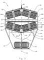
- Figures 1 and 2 show perspective views of a first embodiment of a cleaning device 1A.
- the cleaning device 1A is shown with a frame 10.
- the cleaning device 1A forms a first end portion 11 and a second end portion 12.
- On the frame 10, a movable wing 40 is arranged.
- the movable wing 40 is shown articulated attached to the frame 10.
- the movable wing 40 is arranged to push the cleaning device 1A towards a submerged surface 99, referred to as a net wall in what follows, as shown in figure 5 , when the cleaning device 1A is being moved along the net wall 99.
- each rotatable brushes 20 are arranged in the first end portion 11 of the cleaning device 1A.
- the brushes 20 are paired in a first brush pair 201 and a second brush pair 202.
- Each brush pair 201, 202 is arranged symmetrically around a first axis A1 extending from the first end portion 11 to the second end portion 12.
- a rotatable bottom brush 25 is arranged in the second end portion 12 of the cleaning device 1.
- the bottom brush 25 is, in the main, identical to the rotatable brushes 20.
- the bottom brush 25 is so arranged that the rotational axis of the bottom brush may be perpendicular to the first axis A1.
- the brushes 20, 25 include middle portions 21.
- the brushes are shown with four depth wheels 22.
- a shaft portion 23 is arranged, which is pivotably attached to a rod 13, 14.
- the cleaning device 1 further includes scrapers 30, shown in the figures as fixed brushes.
- the cleaning device 1 is provided with a coupling 80. Via the coupling 80 and a rope or a wire (not shown), the cleaning device 1 may be hoisted and lowered along and on the net wall 99 by means of a winch (not shown).
- Figure 3 shows the cleaning device 1A from the side facing in towards the surface that is to be cleaned.
- the rotational axis 20R of the brushes 20 is slanted relative to the first axis A1.
- the rotational axis 20R and the axis A1 thereby form an angle V1.
- the first brush pair 201 and the second brush pair 202 are arranged symmetrically around a second axis A2, the second axis A2 being perpendicular to the first axis A1.
- the brush pairs 201, 202 form a parallelogram.
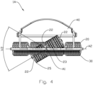
- Figure 4 shows how the brushes 20, 25 can be pivoted around the pivotable attachment 23 within an angle V2, the angle V2 lying over and under a plane formed by the first axis A1 and the second axis A2.
- the bottom brush 25 is shown pivoted around the pivotable attachment 23, whereas the other brushes 20 have not been pivoted.
- Figure 5 shows the cleaning device 1A in a working position on the net wall 99.
- the cleaning device 1A is pulled upwards in a direction D.
- the movable wing 40 will have a first position 40A which is shown in the figure.
- the movable wing 40 is subjected to a downward force F1 by the water flowing past the movable wing 40.
- the movable wing 40 applies a force F2 to the cleaning device 1A towards the net wall 99.
- the force F2 constitutes the ground pressure of the cleaning device 1A against a net wall 99 directed vertically.
- the movable wing 40 When the cleaning device 1A is being lowered downwards, the movable wing 40 will be pivoted and have a second position 40B, and a force F1' will be in the opposite direction to the force F1, so that the force F2 will be of approximately the same magnitude regardless of whether the cleaning device 1A is being moved up or down the net wall 99.
- the cleaning device 1A is shown provided with a movable wing 40. The person skilled in the art will know that a cleaning device 1A may be provided with several movable wings 40.
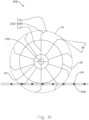
- Figure 6 shows a principle drawing of a net 99 and four brushes 20 arranged in a parallelogram.
- the four brushes are divided into a first brush pair 201 and a second brush pair 202.
- the bristles 26 will work the net 99 in several directions, thereby also cleaning both the threads 96 running in a first direction and the threads 95 running in a second direction in the net 99.
- Figure 7 shows the four brushes 20 of figure 8 arranged in an X-shape.
- Figure 8 shows a principle drawing of the rotatable brush 20 provided with a straight bristle 26, a brush core 29 and a centre axis 290 in accordance with the prior art.
- the straight bristle 26 includes a straight attachment portion 27 and a straight free end portion 28.
- the straight attachment portion 27 is radially attached to the brush core 29.
- the straight free end portion 28 is arranged radially relative to the brush core 29 and forms a circumferential path 31 around the centre axis 290.
- the free end portion 28 forms a secant angle ⁇ equal to 90 degrees with the circumferential path 31.
- the straight free end portion 28 is arranged to penetrate the net 99 when the rotatable brush 20 is rolling along the net 99.
- the working depth of the rotatable brush 20 is restricted by a depth wheel 22 arranged on the brush core 29.
- the depth wheel 22 may be replaced with a depth wheel of a larger or smaller diameter.
- Figure 9 shows a principle drawing of a second rotatable brush 20A provided with a bent bristle 26A.
- the bent bristle 26A comprises a straight attachment portion 27 and a bent free end portion 28A.
- the straight attachment portion 27 is radially attached to the brush core 29.
- the bent free end portion 28A has a deviating direction relative to the straight attachment portion 27 of the bristle 26A, a straight extension 280A from the end 30 of the bristle forming a secant angle ⁇ which is different from 90 degrees with the circumferential path 31.
- the bristle 26A is shown with a secant angle ⁇ of approximately 30 degrees.
- Figure 10 shows a principle drawing of a third rotatable brush 20B provided with a kinked bristle 26B.
- the kinked bristle 26B includes a straight free end portion 28B with a secant angle ⁇ which is equal to the secant angle ⁇ of the first bristle 26A shown in figure 9 .
- the third rotatable brush 20B has the same characteristics as the second rotatable brush 20A shown in figure 9 .
- Figure 11 shows a principle drawing of a fourth rotatable brush 20C provided with a straight bristle 26C tangentially attached to the brush core 29.
- the straight bristle 26C being arranged tangentially as shown in figure 11 , the end portion 28C of the straight bristle 26C forms a secant angle ⁇ with the circumferential path 31 that is different from 90 degrees.
- the secant angle ⁇ is shown as an angle of 77 degrees.
- the secant angle ⁇ can be reduced by increasing the radial distance R between the rotational axis 290 and the attachment portion 27 of the bristle.
- the secant angle ⁇ can be increased by reducing the radial distance R.
- Figure 12 shows a principle drawing of a fifth rotatable brush 20D provided with a plurality of straight bristles 26 and a plurality of bent bristles 26B.
- the bent bristles 26B are arranged in two opposite directions to give the same cleaning effect independently of the direction of rotation of the brush 20D.
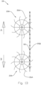
- Figure 13 shows, on a smaller scale, a principle drawing of an alternative embodiment of the cleaning device 1B with two rotatable brushes 20A provided with bent bristles 26A.
- the two rotatable brushes 20A are laterally inverted relative to each other so that the cleaning effect will be the same independently of whether the cleaning device 1B is moved in a direction A or in a direction B.
Landscapes
- Life Sciences & Earth Sciences (AREA)
- Environmental Sciences (AREA)
- Mechanical Engineering (AREA)
- Ocean & Marine Engineering (AREA)
- Combustion & Propulsion (AREA)
- Chemical & Material Sciences (AREA)
- Engineering & Computer Science (AREA)
- Animal Husbandry (AREA)
- Marine Sciences & Fisheries (AREA)
- Biodiversity & Conservation Biology (AREA)
- Cleaning In General (AREA)
- Brushes (AREA)
- Crystals, And After-Treatments Of Crystals (AREA)
- Mechanical Treatment Of Semiconductor (AREA)
- Electrical Discharge Machining, Electrochemical Machining, And Combined Machining (AREA)
- Current-Collector Devices For Electrically Propelled Vehicles (AREA)
Description
- The invention relates to a rotatable brush for cleaning a submerged net, for example a net belonging to a fish-farming cage. More specifically, the invention relates to a cleaning device with rotatable brushes.
- The rotatable brushes are passive and without a dedicated motor for driving the brushes. The brushes are brought to rotate by being moved across and in contact with the surface that is to be cleaned. Preferably, the cleaning device is moved across the surface in a vertical direction by the cleaning device preferably being lowered and hoisted by means of a winch which is positioned above a water surface. More specifically still, the cleaning device includes one or more brushes having rotational axes that are slanted relative to a direction in which the cleaning device is being moved. In addition, the cleaning device may include one or more rotatable brushes that are transverse relative to the direction in which the cleaning device is being moved. More specifically still, the rotatable brushes are pivotably attached and pivotable around axes perpendicular to the rotational axes of the brushes.
- For fish-farming, floating cages can be used. A so-called open cage includes, among other things, a floating body encircling an enclosure for the fish. The enclosure may comprise a net. The net is closed at the bottom. The water flows freely through the net. The fish is dependent on the water within the net being replaced by flow-through, for the oxygen content of the water to be satisfactory. Over time, the net will become covered in fouling, and the water flow decreases. The oxygen content inside the cage will therefore decrease, which is unfavourable for the well-being, health and growth of the fish.
- It is known to use so-called cleaner fish in cages to combat external crustacean parasites on the fish. The salmon louse is one example of such a parasite. It is favourable to keep the net clean of fouling to have the best effect of the cleaner fish. The cleaner fish will feed on fouling and, therefore, will not eat salmon lice so actively when the net is fouled.
- It is known in the trade to treat nets that are used for cages with impregnating agents to prevent fouling. Such impregnating agents are toxic in nature. Known impregnating agents comprise cupriferous impregnating agents. It is also known that such nets must be sent to special washing facilities for cleaning and re-impregnation. This is extensive work which includes, inter alia, mobilizing a boat with a crane to be able to lift the net out of the sea and to put the net back into the sea.
- An alternative to washing and impregnating the nets is cleaning the nets in situ in the water.
-
Patent document US 2011/0185519 discloses a device for cleaning a submerged net, especially a net in a fish cage. The device is operated from a surface vessel. The device includes a rectangular or square chassis which is arranged to slide across the net. The device includes buoyancy bodies which are placed within the frame, a propulsion means for the device to be movable along the net, a propeller for keeping the device close to and in contact with the net, and a cleaning means. The cleaning means may include a suction device integrated in the chassis, or a high-pressure washer. In addition, the device may be provided with brushes. The propulsion device may comprise hydraulically driven toothed sprockets. The propeller may be driven hydraulically. The buoyancy body is adapted for the device to have a negative buoyancy of about 10 kg in a fully submerged position. -
Patent document EP 2251102 discloses another device for cleaning a submerged net. The device is a device running on wheels and being securely held from the surface. Energy is supplied from the surface through a cable, and pressurized liquid is supplied from the surface through a hose. Cleaning is performed by high-pressure washing the net. -
Patent document WO 2015/005801 discloses an autonomous device for cleaning a submerged net. The device comprises wheels for propulsion across the net, a propeller for positioning the device against the net, rotating brushes for cleaning, buoyancy means and a battery for energy supply. It is also known to use devices provided with tracks as an alternative to wheels. - Patent document
NO 20160538 Patent document US 2012/0260443 discloses a cleaning device comprising a frame provided with several rotating discs for cleaning a net. At their circumferences, the discs are provided with finger-shaped hooks which grip around the net structure and loosen impurities. A substantial drawback of this solution is the fact that the hooks give a considerable mechanical strain on the net structure. - The applicant's own patent application
NO 20161527 -
CA 2 260 560 A1 andWO 2015/126261 A1 disclose each a rotatable brush according to the preamble of claim 1. - Some of the known devices have the drawback, among others, of having to be operated from the surface, from a workboat. The workboat preferably has a crane. Because of the work in mobilizing a boat and crew, cleaning will not be carried out until the fouling has become relatively extensive. Devices including the use of water under high pressure are known to give heavy wear on the nets, whereas gentle devices may have low capacity. There is therefore a need for a device that can clean the net in a gentle manner regularly and before the fouling has become extensive.
- The invention has for its object to remedy or reduce at least one of the drawbacks of the prior art or at least provide a useful alternative to the prior art.
- The object is achieved through the features that are specified in the claims that follow.
- The invention is defined by the independent claim. The dependent claims define advantageous embodiments of the invention.
- The invention relates to a rotatable brush for cleaning a submerged net, according to claim 1.
- By a submerged surface may be understood, in this connection, an enclosure for farmed fish, for example a net that is submerged in water. The net may form a net wall which may be vertical or sloping. In what follows, the submerged surface will be referred to as a net. The net may form a net wall which may be vertical or sloping. The net wall may be provided with threads arranged vertically and horizontally.
- A rotatable brush, technically also referred to as a roller brush, has the advantage of the rotatable brush rolling across the net, thereby loosening impurities that have attached to the net, for example algal growths. By the brush rolling on the net, a passive and gentle cleaning of the net is achieved with minimal strain on the net and with minimal whirling-up of impurities.
- Rotation of the rotatable brush may be provided by the rotatable brush rolling across a supporting face, for example a net. Rotation of the rotatable brush may be provided by the rotatable brush being connected to a driving means, for example a motor. A driven rotatable brush may be given a rotational speed that is independent of the relative motion of the brush against the supporting face.
- The first axis of the cleaning device substantially coincides with the direction of motion of the cleaning device, and, in the position of application of the cleaning device, the first axis is, in the main, parallel to the net wall. Currents in the water may cause some motion in the net, so that a net wall that is normally vertical may become slanted.
- The cleaning device is arranged to be lifted and lowered by means of a winch on the surface. The cleaning device may clean the net wall when moving downwards as well as when moving upwards along the net wall. The cleaning device may include at least one movable wing arranged to push the cleaning device against the wall when the cleaning device is moving both downwards and upwards along the net wall.
- Tests, which have been carried out by the applicant, show that a slanted brush as described herein may give a substantially better cleaning effect than a transverse brush with a rotational axis that is perpendicular to the first axis. The better cleaning effect is achieved in that the slanted brushes clean both the horizontal threads and the vertical threads in the net when the brush is rolling along the net wall. Tests show, among other things, that a cleaning device including two transverse brushes can give a 40 per cent cleaning effect after 336 passes. A cleaning device with a plurality of slanted brushes may give an 80 per cent cleaning effect after 40 passes and 100 per cent cleaning effect after 80 passes.
- The cleaning device may include a first brush pair arranged in a V-shape. Two slanted brushes in a V-shape have the advantage of lateral forces due to the rotation of the slanted brushes being equalized, and of the cleaning device moving more stably along the net wall in a vertical direction. One slanted brush, or possibly two parallel slanted brushes, may lead to the brushes pulling the cleaning device sideways when the brushes are rolling on the net wall.
- The cleaning device may further include a second brush pair arranged in a V-shape. This has the advantage of two brush pairs arranged in V-shapes being able to further increase the stability sideways while, at the same time, the cleaning effect will be the same whether the cleaning device is moving upwards or downwards on the net wall.
- The second brush pair may be laterally inverted around the second axis relative to the first brush pair. This has the advantage of the lateral inversion of the positioning of the brushes giving a symmetric design which contributes to an optimum cleaning effect whether the cleaning device is moving upwards or downwards on the net wall. A laterally inverted positioning will also give very good directional stability when the cleaning device is rolling across the net wall.
- The two brush pairs may be arranged in an X-shape or as a parallelogram. A parallelogram is considered the most space-efficient. The cleaning effect can be influenced by changing the mutual angle of the brushes.
- The second end portion of the cleaning device may include a bottom brush. The second end portion faces downwards in the net when the cleaning device is in a normal operative position. The bottom brush is particularly favourable when the cleaning device is used in a so-called coned net. In a coned net, there may be too little space at the bottom of the net for the entire cleaning device. By giving the second end portion of the cleaning device a tapering shape and providing the second end portion with a bottom brush, the bottom brush may clean the lowermost portion of the net which is not accessible to the rotatable brush pairs. The rotational axis of the bottom brush may be perpendicular to the first axis, or it may be so arranged that an angle is formed between the rotational axis and the first axis.
- The cleaning device may include at least one scraper. This has the advantage of the scraper being arranged to give an extra cleaning of the net or the supporting face by scraping dirt that the rotatable brushes possibly have not managed to loosen off the surface. The at least one scraper additionally functions as a support and a spacer against the supporting face, thereby contributing to the cleaning device having a distance as constant as possible to the supporting face.
- A portion of the scraper may be parallel to the rotational axis of a brush. This has the effect of saving space. One or more scrapers may be arranged parallel to the rotational axis and near the rotatable brush. By the scraper being arranged parallel to the rotatable brush, there will be no wedge between the brush and scraper in which fish or other objects in the water may become wedged. When four brushes are arranged in a parallelogram and there is a scraper arranged parallel to each of the four brushes, two paired scrapers will form a V-shape like a plough. When the cleaning device is pulled upwards along the net wall, the two uppermost scrapers can guide away larger impurities on the net wall in order thereby to increase the cleaning effect of the rotatable brushes. When the cleaning device is lowered downwards along the net wall, the lowermost scrapers will give a corresponding effect.
- The scraper may include a fixed brush. This has the advantage of a fixed brush comprising bristles being more effective under some conditions than a stiff scraper of, for example, rubber or metal. When the fixed brush is moved along a perforated supporting face, for example a net, the perforated supporting face may induce a vibrating effect in the bristles, which increases the cleaning effect.
- The rotatable brush may, in the main, be cylindrically shaped around the rotational axis.
- The effect of a cylinder-shaped rotatable brush is that the rotational axis of the brush core may create a constant distance to the supporting face when the brush is rolling across the supporting face. A cleaning device provided with a rotatable brush as described herein may thereby provide a stable and even motion when the cleaning device is being moved along the supporting face. A constant distance to the supporting face is particularly important if the cleaning device is lifted and lowered vertically in a fish cage, for example by the use of a winch.
- The rotatable brush may include at least one depth wheel.
- This has the advantage of the depth wheel, which is arranged coaxially with the brush, giving the brush an even ground pressure against the net, and the depth wheel restricting the working depth of the brush; that is to say, how far through the net the bristle of the brush may go. The brush may be provided with alternative depth wheels of different diameters so that the working depth of the brush may be adapted to the supporting face, for example to the thread thickness and mesh of the net and to the fibre length of the bristle. A depth wheel of a small diameter is arranged to give a large working depth. A depth wheel of a large diameter is arranged to give a small working depth. The depth wheel may be replaceable for the working depth to be adapted to the supporting face, for example to the thread thickness and mesh of the net and to the length of the bristle. Further, the depth wheel, which is arranged coaxially with the brush core, may contribute to a more even ground pressure against the supporting face compared with a rotatable brush without a depth wheel.
- Two depth wheels may be arranged axially, one on either side of the rotatable brush. The rotatable brush may include a middle portion with an attachment for pivotable attachment of the brush. The advantage of this is that by providing the brush with a centred pivotable attachment, the rotational axis of the brush may be pivoted so that the brush may better follow an uneven supporting face. By the pivotable attachment being at the centre of the brush, the brush may balance around the attachment and thereby roll in the easiest possible way on the supporting face.
- The rotatable brush may include a middle portion with an attachment for a pivotable attachment of the brush.
- The advantage of providing the brush with a centered pivotal attachment, is that the rotation axis of the brush can be rotated so that the brush can better follow an uneven supporting face. By having the pivotal attachment in the center of the brush, the brush can balance about the fastening and thereby roll most easily on the supporting surface.
- The middle portion may include at least one depth wheel. The middle portion may include one or two depth wheels. To simplify the structure, the middle portion may be provided with just one depth wheel.
- The second end portion of the cleaning device may be wedge-shaped.
- A design like that has the advantage of enabling the cleaning device to be moved further down in a coned net than a cleaning device with an end portion of a rectangular shape.
- The rotatable brush according to the invention includes a brush core with a rotational axis and a plurality of bristles, wherein the bristle is provided with an end portion with a free end and with an opposite attachment portion attached to the brush core. When the rotatable brush is rotated, the free end of the bristle moves along a circular circumferential path with the centre on the rotational axis. The end portion of the bristle forms a secant angle with the circumferential path, the secant angle being different from 90 degrees.
- By a circular circumferential path may be understood, in this connection, a circumferential path associated with a single bristle. Bristles of different lengths may have circumferential paths of different radii.
- In what follows, a bristle with a secant angle different from 90 degrees will be referred to as a bent bristle or a tangential bristle. By a submerged surface may be understood, in this connection, an enclosure for farmed fish, for example a net submerged in water. In what follows, the submerged surface will be referred to as a net.
- When a bristle directed radially with a secant angle of 90 degrees penetrates the net, the straight bristle will, in the main, only touch the fronts and sides of the threads in the net. In this connection, the front may be understood as the surface facing the cleaning device.
- The rotatable brush may comprise a plurality of radial bristles, and a number of bristles may deviate from a radial direction at their free end portions. When a radially directed bust penetrates the net, the straighten bristles will essentially only touch the front and side of the threads of the net. In this connection, the front may be understood as the surface facing the cleaning device. By giving bristles a deviating direction at their free end portions, for example in the form of a bend or a kink, the bristle may also work the back of the threads in the net.
- Trials carried out by the applicant show that a rotatable brush with straight bristles may achieve a cleaning of the back of the threads in the net of 10 per cent as the maximum. By a straight bristle may be understood, in this connection, a bristle in which the end portion of the bristle is arranged radially to the rotational axis of the brush core, so that a secant angle of 90 degrees is formed between the end portion of the bristle and the circumferential path.
- By giving the free end portion of the bristle a secant angle different from 90 degrees, for example of between 30 and 60 degrees, the bristle may also work the back of the treads in the net. According to said trials, a rotatable brush with a free end portion having a secant angle smaller or larger than 90 degrees may give a 100 per cent cleaning of the back of the threads in the net. The end portion arranged non-radially described herein is formed by giving the bristle a kink or a bend. The bend may extend to the free end of the bristle.
- The rotatable brush includes bent bristles. The bent bristles may have identical or different bends and lengths in their free end portions.
- One or more brushes may be arranged in a cleaning device. By a cleaning device may be understood, in this connection, a device including at least one rotatable brush, the cleaning device being arranged to be lifted and lowered along the net wall by means of a winch on the surface. The cleaning device may clean the net wall when moving downwards as well as when moving upwards along the net wall. In the main, the cleaning device usually moves along the vertical threads and transversely to the horizontal threads in the net. The attachment portion of the bristle may be arranged radially in the brush core.
- The effect of an attachment portion arranged radially is that the strain on the attachment portion of the bristle will be the same, independently of the direction of rotation of the brush. Further, an attachment portion arranged radially makes it possible to arrange bristles having identical secant angles in a first direction of rotation and in a second direction of rotation, the bristles in opposite arrangement having circular circumferential paths of identical radii.
- The attachment portion of the bristle may be arranged tangentially to the brush core.
- According to an embodiment that does not form part of the invention, the effect of the attachment portion of the bristle being arranged tangentially to the brush core is that, with a straight bristle, a secant angle between the end portion of the bristle and the circumferential path that is different from 90 degrees can be achieved. A straight bristle as described herein has the advantage of being able to apply a greater force against the supporting face than a bent bristle, as a bent bristle will bend more easily than a straight bristle when the end portion of the bristle is subjected to a force component directed towards the attachment portion of the bristle.
- The rotatable brush may include bristles of different types.
- By different types may be understood, in this connection, bristles of different shapes, different cross sections, different lengths and different materials.
- The effect of providing the rotatable brush with different types of bristles is that the cleaning effect can be adapted for the conditions. The rotatable brush may, for example, include a combination of long stiff bristles arranged for rough cleaning and soft short bristles for fine cleaning. The rotatable brush may include only bent bristles or a combination of straight and bent bristles. The bent bristles may have identical or different bends and lengths.
- The various bristles may be arranged systematically, for example in a helical shape, or they may be arranged randomly on the rotatable brush. Bristles of different lengths may advantageously be arranged evenly distributed around the circumference so that the rotatable brush may roll evenly across the surface. The various bristles may be so arranged that the cleaning effect of the rotatable brush is independent of the direction of rotation. This can be achieved, for example, by arranging approximately equal numbers of bent bristles in a first direction of rotation and in a second direction of rotation.
- The bristle may be formed from fibre, synthetic material or metal, or a combination of several materials. The cross section of the bristle may be circular, polygonal or elliptical. By providing the bristle with an elliptical or polygonal cross section, it is possible to give the bristle a directional stiffness. A stiff bristle with a polygonal cross section, for example square, may give a more aggressive cleaning than a soft bristle with a circular cross section.
- In a cleaning device in which four brushes are arranged in a parallelogram or an X-shape, brushes with bent bristles may be arranged in such a way that the bristles of the first and second brush pairs are arranged in opposite directions. Thereby the cleaning effect will be the same whether the cleaning device is moving upwards or downwards on the net wall.
- In what follows, an example of a preferred embodiment is described, which is visualized in the accompanying drawings, in which:
- Figure 1
- shows a perspective view of a cleaning device according to the invention, in which the cleaning device is viewed from a side facing in towards a supporting face that is to be cleaned;
- Figure 2
- shows a perspective view of the cleaning device seen from an opposite side to that in
figure 1 ; - Figure 3
- shows a plan view of the side of the cleaning device facing in towards the supporting face that is to be cleaned;
- Figure 4
- shows a side view of the cleaning device seen from the tapering end portion of the cleaning device;
- Figure 5
- shows a side view of the cleaning device in a position of application on a supporting face that is to be cleaned;
- Figure 6
- shows a schematic view of four rotatable brushes arranged in a parallelogram;
- Figure 7
- shows a schematic view of four rotatable brushes arranged in an X-shape;
- Figure 8
- shows, on a larger scale, a prior-art rotatable brush with straight bristles;
- Figure 9
- shows a rotatable brush with bent bristles;
- Figure 10
- shows a rotatable brush with kinked bristles;
- Figure 11
- shows a rotatable brush with straight bristles with tangential attachment;
- Figure 12
- shows a rotatable brush with different types of bristles; and
- Figure 13
- shows, on a smaller scale, a schematic side view of a cleaning device with two rotatable brushes with bent bristles.
- In the figures, the
reference numeral 1A refers to a cleaning device according to the invention. -
Figures 1 and2 show perspective views of a first embodiment of acleaning device 1A. Thecleaning device 1A is shown with aframe 10. Thecleaning device 1A forms afirst end portion 11 and asecond end portion 12. On theframe 10, amovable wing 40 is arranged. Themovable wing 40 is shown articulated attached to theframe 10. Themovable wing 40 is arranged to push thecleaning device 1A towards a submergedsurface 99, referred to as a net wall in what follows, as shown infigure 5 , when thecleaning device 1A is being moved along thenet wall 99. - In the
first end portion 11 of thecleaning device 1A, fourrotatable brushes 20 are arranged. Thebrushes 20 are paired in afirst brush pair 201 and asecond brush pair 202. Eachbrush pair first end portion 11 to thesecond end portion 12. - In the
second end portion 12 of the cleaning device 1, a rotatablebottom brush 25 is arranged. By design, thebottom brush 25 is, in the main, identical to the rotatable brushes 20. Thebottom brush 25 is so arranged that the rotational axis of the bottom brush may be perpendicular to the first axis A1. - The
brushes middle portions 21. The brushes are shown with fourdepth wheels 22. In themiddle portion 21, ashaft portion 23 is arranged, which is pivotably attached to arod brushes rods scrapers 30, shown in the figures as fixed brushes. At itsfirst end portion 11, the cleaning device 1 is provided with acoupling 80. Via thecoupling 80 and a rope or a wire (not shown), the cleaning device 1 may be hoisted and lowered along and on thenet wall 99 by means of a winch (not shown). -
Figure 3 shows thecleaning device 1A from the side facing in towards the surface that is to be cleaned. Therotational axis 20R of thebrushes 20 is slanted relative to the first axis A1. Therotational axis 20R and the axis A1 thereby form an angle V1. Thefirst brush pair 201 and thesecond brush pair 202 are arranged symmetrically around a second axis A2, the second axis A2 being perpendicular to the first axis A1. In the figure, the brush pairs 201, 202 form a parallelogram. -
Figure 4 shows how thebrushes pivotable attachment 23 within an angle V2, the angle V2 lying over and under a plane formed by the first axis A1 and the second axis A2. Infigure 4 , thebottom brush 25 is shown pivoted around thepivotable attachment 23, whereas theother brushes 20 have not been pivoted. -
Figure 5 shows thecleaning device 1A in a working position on thenet wall 99. Thecleaning device 1A is pulled upwards in a direction D. When thecleaning device 1A is pulled in the direction D, themovable wing 40 will have afirst position 40A which is shown in the figure. When themovable wing 40 is in thefirst position 40A, themovable wing 40 is subjected to a downward force F1 by the water flowing past themovable wing 40. Themovable wing 40 applies a force F2 to thecleaning device 1A towards thenet wall 99. The force F2 constitutes the ground pressure of thecleaning device 1A against anet wall 99 directed vertically. When thecleaning device 1A is being lowered downwards, themovable wing 40 will be pivoted and have asecond position 40B, and a force F1' will be in the opposite direction to the force F1, so that the force F2 will be of approximately the same magnitude regardless of whether thecleaning device 1A is being moved up or down thenet wall 99. It should be noted that thecleaning device 1A is shown provided with amovable wing 40. The person skilled in the art will know that acleaning device 1A may be provided with severalmovable wings 40. - The
scrapers 30 rest against thenet wall 99, thereby restricting the working depth of thebrushes figure 5 , it is shown that a portion of thenet wall 99 forms abulge 98. In thebulge 98, the working depth of thebrush 25 is restricted by thedepth wheel 22 arranged at thebrush 25. -
Figure 6 shows a principle drawing of a net 99 and fourbrushes 20 arranged in a parallelogram. The four brushes are divided into afirst brush pair 201 and asecond brush pair 202. By thebrushes 20 being slanted, thebristles 26 will work the net 99 in several directions, thereby also cleaning both thethreads 96 running in a first direction and thethreads 95 running in a second direction in the net 99. -
Figure 7 shows the four brushes 20 offigure 8 arranged in an X-shape. -
Figure 8 shows a principle drawing of therotatable brush 20 provided with astraight bristle 26, abrush core 29 and acentre axis 290 in accordance with the prior art. The straight bristle 26 includes astraight attachment portion 27 and a straightfree end portion 28. Thestraight attachment portion 27 is radially attached to thebrush core 29. The straightfree end portion 28 is arranged radially relative to thebrush core 29 and forms acircumferential path 31 around thecentre axis 290. Thefree end portion 28 forms a secant angle α equal to 90 degrees with thecircumferential path 31. The straightfree end portion 28 is arranged to penetrate the net 99 when therotatable brush 20 is rolling along the net 99. The working depth of therotatable brush 20 is restricted by adepth wheel 22 arranged on thebrush core 29. Thedepth wheel 22 may be replaced with a depth wheel of a larger or smaller diameter. -
Figure 9 shows a principle drawing of a secondrotatable brush 20A provided with abent bristle 26A. The bent bristle 26A comprises astraight attachment portion 27 and a bentfree end portion 28A. Thestraight attachment portion 27 is radially attached to thebrush core 29. The bentfree end portion 28A has a deviating direction relative to thestraight attachment portion 27 of thebristle 26A, astraight extension 280A from theend 30 of the bristle forming a secant angle α which is different from 90 degrees with thecircumferential path 31. Thebristle 26A is shown with a secant angle α of approximately 30 degrees. When therotatable brush 20 is rolling on thenet wall 99, the bentfree end portion 28A will contribute to the back 99B of thenet wall 99 being cleaned as well. -
Figure 10 shows a principle drawing of a thirdrotatable brush 20B provided with a kinkedbristle 26B. The kinked bristle 26B includes a straightfree end portion 28B with a secant angle α which is equal to the secant angle α of the first bristle 26A shown infigure 9 . Otherwise, the thirdrotatable brush 20B has the same characteristics as the secondrotatable brush 20A shown infigure 9 . -
Figure 11 shows a principle drawing of a fourthrotatable brush 20C provided with astraight bristle 26C tangentially attached to thebrush core 29. By the straight bristle 26C being arranged tangentially as shown infigure 11 , theend portion 28C of the straight bristle 26C forms a secant angle α with thecircumferential path 31 that is different from 90 degrees. The secant angle α is shown as an angle of 77 degrees. The secant angle α can be reduced by increasing the radial distance R between therotational axis 290 and theattachment portion 27 of the bristle. The secant angle α can be increased by reducing the radial distance R. -
Figure 12 shows a principle drawing of a fifthrotatable brush 20D provided with a plurality ofstraight bristles 26 and a plurality ofbent bristles 26B. The bent bristles 26B are arranged in two opposite directions to give the same cleaning effect independently of the direction of rotation of thebrush 20D. -
Figure 13 shows, on a smaller scale, a principle drawing of an alternative embodiment of thecleaning device 1B with tworotatable brushes 20A provided withbent bristles 26A. - The two
rotatable brushes 20A are laterally inverted relative to each other so that the cleaning effect will be the same independently of whether thecleaning device 1B is moved in a direction A or in a direction B. - It should be noted that all the above-mentioned embodiments illustrate the invention, but do not limit it, and persons skilled in the art may construct many alternative embodiments without departing from the scope of the attached claims. In the claims, reference numbers in brackets are not to be regarded as restrictive.
- The use of the verb "to comprise" and its different forms does not exclude the presence of elements or steps that are not mentioned in the claims. The indefinite article "a" or "an" before an element does not exclude the presence of several such elements.
Claims (7)
- A rotatable brush (20A-B, D) for cleaning a submerged net (99) where the rotatable brush (20A-A, D) comprises;- a brush core (29) with a rotational axis (290); and- a plurality of bristles (26A-B), where each bristle (26A-B) is provided with an end portion comprising a free end (30) and an opposite attachment portion (27) attached to the brush core (29),where a rotation of the rotatable brush (20A-B, D) moves each bristle's (26A-B) free end (30) along a circular circumferential path (31) with a centre in the rotational axis (290), the end portion of each bristle (26A-B) forms a secant angle (α) with the circumferential path (31), the secant angle (α) being different from 90 degrees, characterized in that each bristle (26A-B) at the end portion is formed with a kink or a bend.
- The rotatable brush (20A-B, D) according to claim 1, wherein the attachment portion (27) is arranged radially in the brush core (29).
- The rotatable brush (20A-B, D) according to any one of the preceding claims,
wherein the rotatable brush (20A-B, D) is cylindrically shaped around the rotational axis (290). - The rotatable brush (20A-B, D) according to any one of the preceding claims,
wherein the rotatable brush (20A-B, D) comprises bristles (26, 26A-B) of different types. - The rotatable brush (20A- B, D) according to any one of the preceding claims,
wherein the rotatable brush (20A-B, D) comprises at least one depth wheel. - The rotatable brush (20A-B, D) according to any one of the preceding claims,
wherein the rotatable brush (20A-B, D) comprises a middle portion with an attachment for pivotable attachment of the brush to a cleaning device (1A) for rotation of the rotational axis (290). - A cleaning device (1A-B) for a submerged net (99), wherein the cleaning device (1A-B) comprises a rotatable brush (20A-B, D) according to any one of the preceding claims.
Applications Claiming Priority (4)
| Application Number | Priority Date | Filing Date | Title |
|---|---|---|---|
| NO20180118A NO343977B1 (en) | 2018-01-25 | 2018-01-25 | Diving surface cleaner |
| NO20181124A NO344164B1 (en) | 2018-01-25 | 2018-08-28 | Rotatable brush for a submersible cleaner |
| EP19743883.1A EP3742896A4 (en) | 2018-01-25 | 2019-01-22 | CLEANING DEVICE FOR A SUBMERGED SURFACE |
| PCT/NO2019/050012 WO2019147137A1 (en) | 2018-01-25 | 2019-01-22 | Cleaning device for a submerged surface |
Related Parent Applications (1)
| Application Number | Title | Priority Date | Filing Date |
|---|---|---|---|
| EP19743883.1A Division EP3742896A4 (en) | 2018-01-25 | 2019-01-22 | CLEANING DEVICE FOR A SUBMERGED SURFACE |
Publications (2)
| Publication Number | Publication Date |
|---|---|
| EP4085764A1 EP4085764A1 (en) | 2022-11-09 |
| EP4085764B1 true EP4085764B1 (en) | 2024-11-06 |
Family
ID=67701231
Family Applications (2)
| Application Number | Title | Priority Date | Filing Date |
|---|---|---|---|
| EP19743883.1A Withdrawn EP3742896A4 (en) | 2018-01-25 | 2019-01-22 | CLEANING DEVICE FOR A SUBMERGED SURFACE |
| EP22171418.1A Active EP4085764B1 (en) | 2018-01-25 | 2019-01-22 | Rotatable brush for cleaning a submerged net |
Family Applications Before (1)
| Application Number | Title | Priority Date | Filing Date |
|---|---|---|---|
| EP19743883.1A Withdrawn EP3742896A4 (en) | 2018-01-25 | 2019-01-22 | CLEANING DEVICE FOR A SUBMERGED SURFACE |
Country Status (10)
| Country | Link |
|---|---|
| EP (2) | EP3742896A4 (en) |
| KR (2) | KR20200111229A (en) |
| CN (1) | CN111787790A (en) |
| AU (1) | AU2019211023B2 (en) |
| CA (2) | CA3089570A1 (en) |
| CL (1) | CL2020001953A1 (en) |
| DK (2) | DK202070491A1 (en) |
| ES (1) | ES3011083T3 (en) |
| NO (2) | NO343977B1 (en) |
| WO (1) | WO2019147137A1 (en) |
Families Citing this family (8)
| Publication number | Priority date | Publication date | Assignee | Title |
|---|---|---|---|---|
| CN112918631A (en) * | 2021-02-05 | 2021-06-08 | 徐州蓝湖信息科技有限公司 | But hull descaling machine of automatically regulated angle |
| CN113118093B (en) * | 2021-04-15 | 2022-06-07 | 哈尔滨工程大学 | Ultrasonic net cage cleaning device based on underwater robot |
| CN114832632B (en) * | 2022-04-25 | 2023-08-15 | 北京华宇辉煌生态环保科技股份有限公司 | Sewage dynamic membrane cleaning device |
| CN115071906B (en) * | 2022-08-23 | 2022-11-08 | 威海海洋职业学院 | Ship bottom adsorption biological treatment device |
| CN116420671B (en) * | 2023-06-01 | 2024-04-26 | 惠州市海燕水产养殖科技有限公司 | Efficient circulating aquaculture system |
| CN117696511B (en) * | 2024-02-06 | 2024-04-19 | 洛阳市洛龙区河渠事务中心 | Rubber dam underwater cleaning head and cleaning equipment with the cleaning head |
| WO2025183419A1 (en) * | 2024-02-28 | 2025-09-04 | 주식회사 타스글로벌 | Roller-type brush for cleaning hull |
| WO2026012077A1 (en) * | 2024-07-12 | 2026-01-15 | 北京石头世纪科技股份有限公司 | Cleaning brush head and cleaning apparatus |
Citations (11)
| Publication number | Priority date | Publication date | Assignee | Title |
|---|---|---|---|---|
| US4030440A (en) | 1976-03-24 | 1977-06-21 | Floyd David Wickersham | Boat cleaning machine |
| DE4112382A1 (en) | 1991-04-16 | 1992-10-22 | Heinz Fritze | Floor or road sweeper with brush roller or plate - has angled bristle ends, and self-cleaning guide plates, with adjustable positioned rollers |
| GB2257350A (en) | 1991-07-09 | 1993-01-13 | Thomas Edward Eatenton | Boat cleaning |
| US5930862A (en) * | 1998-01-09 | 1999-08-03 | Garrett; Barbara I. | Rug rake |
| CA2260560A1 (en) | 1999-02-01 | 2000-08-01 | Sweeprite Manufacturing Inc. | Rotary brush with decreased trash throw outside swath |
| US6568028B2 (en) | 1999-04-27 | 2003-05-27 | Putics Gyoengyi | Carpet-cleaning brush |
| WO2012142364A2 (en) | 2011-04-13 | 2012-10-18 | Lindgren Peter B | Fish cage screen and cleaning apparatus |
| WO2013126359A2 (en) | 2012-02-24 | 2013-08-29 | Lindgren Peter B | Aquaculture cage screen and cleaning apparatus |
| WO2015126261A1 (en) | 2014-02-24 | 2015-08-27 | Lateral As | Cleaning apparatus and use of the same |
| US9554642B2 (en) | 2006-03-13 | 2017-01-31 | Monti-Werkzeuge Gmbh | Power brush |
| WO2018056835A1 (en) | 2016-09-23 | 2018-03-29 | Aqua Robotics As | Device for cleaning a surface of a structure, the surface being submerged in a water column |
Family Cites Families (17)
| Publication number | Priority date | Publication date | Assignee | Title |
|---|---|---|---|---|
| US3431571A (en) * | 1966-10-26 | 1969-03-11 | Donald Edward Kraus | Rotary driven hairbrush |
| NO137849C (en) * | 1976-11-09 | 1978-05-10 | Christensen Engineering As | UNDERWATER BRUSH MACHINE. |
| US5175591A (en) * | 1991-08-21 | 1992-12-29 | Xerox Corporation | Cleaning device including abrading cleaning brush for comet control |
| US5903951A (en) * | 1995-11-16 | 1999-05-18 | Minnesota Mining And Manufacturing Company | Molded brush segment |
| CA2297677A1 (en) * | 1999-02-01 | 2000-08-01 | Sweeprite Manufacturing Inc. | Rotary brush with decreased trash throw outside brush path |
| CN100559940C (en) * | 2005-08-30 | 2009-11-18 | 浙江海洋学院 | Net cage underwater dirt cleaning device |
| AU2008350457B2 (en) | 2008-02-14 | 2012-05-03 | Yanmar Co., Ltd. | Underwater cleaning robot and auxiliary cleaning work machine |
| NO328058B1 (en) * | 2008-03-04 | 2009-11-23 | Happy Fish As | Cleaning device for an underwater structure and method for using it |
| CN102215674B (en) | 2008-10-10 | 2013-07-17 | 米克股份有限公司 | In situ sub marine net cleaning and inspecting device |
| US20120260443A1 (en) | 2011-04-13 | 2012-10-18 | Lindgren Peter B | Aquaculture cage screen and cleaning apparatus |
| CN202873549U (en) * | 2012-11-13 | 2013-04-17 | 姜仁瑞 | Removal device for attachments on aquaculture net cage |
| NO336915B1 (en) * | 2013-07-12 | 2015-11-23 | Ole Molaug Eiendom As | Autonomous surface cleaning device for a dive structure |
| ES2739198T3 (en) * | 2014-06-19 | 2020-01-29 | Univ King Abdullah Sci & Tech | Cleaning device |
| NO344054B1 (en) | 2016-04-05 | 2019-08-26 | Hydratech As | Vessels for cleaning a submerged structure |
| CN205628713U (en) * | 2016-04-25 | 2016-10-12 | 广东溢达纺织有限公司 | Rotary dust cleaning apparatus |
| CN106238371B (en) * | 2016-10-21 | 2019-01-08 | 华南农业大学 | A kind of deep-sea domain aquaculture net cage automatic flushing device |
| NO342552B1 (en) * | 2016-12-08 | 2018-06-11 | Mohn Drilling As | Autonomous cleaning and inspection robot for use in a fish farm |
-
2018
- 2018-01-25 NO NO20180118A patent/NO343977B1/en unknown
- 2018-08-28 NO NO20181124A patent/NO344164B1/en unknown
-
2019
- 2019-01-22 EP EP19743883.1A patent/EP3742896A4/en not_active Withdrawn
- 2019-01-22 KR KR1020207024345A patent/KR20200111229A/en not_active Ceased
- 2019-01-22 CA CA3089570A patent/CA3089570A1/en active Pending
- 2019-01-22 ES ES22171418T patent/ES3011083T3/en active Active
- 2019-01-22 CA CA3204519A patent/CA3204519A1/en active Pending
- 2019-01-22 WO PCT/NO2019/050012 patent/WO2019147137A1/en not_active Ceased
- 2019-01-22 KR KR1020237020069A patent/KR20230092027A/en not_active Ceased
- 2019-01-22 CN CN201980016066.0A patent/CN111787790A/en active Pending
- 2019-01-22 AU AU2019211023A patent/AU2019211023B2/en not_active Expired - Fee Related
- 2019-01-22 EP EP22171418.1A patent/EP4085764B1/en active Active
-
2020
- 2020-07-16 DK DKPA202070491A patent/DK202070491A1/en not_active Application Discontinuation
- 2020-07-24 CL CL2020001953A patent/CL2020001953A1/en unknown
-
2022
- 2022-04-26 DK DKPA202270218A patent/DK181512B1/en active IP Right Grant
Patent Citations (11)
| Publication number | Priority date | Publication date | Assignee | Title |
|---|---|---|---|---|
| US4030440A (en) | 1976-03-24 | 1977-06-21 | Floyd David Wickersham | Boat cleaning machine |
| DE4112382A1 (en) | 1991-04-16 | 1992-10-22 | Heinz Fritze | Floor or road sweeper with brush roller or plate - has angled bristle ends, and self-cleaning guide plates, with adjustable positioned rollers |
| GB2257350A (en) | 1991-07-09 | 1993-01-13 | Thomas Edward Eatenton | Boat cleaning |
| US5930862A (en) * | 1998-01-09 | 1999-08-03 | Garrett; Barbara I. | Rug rake |
| CA2260560A1 (en) | 1999-02-01 | 2000-08-01 | Sweeprite Manufacturing Inc. | Rotary brush with decreased trash throw outside swath |
| US6568028B2 (en) | 1999-04-27 | 2003-05-27 | Putics Gyoengyi | Carpet-cleaning brush |
| US9554642B2 (en) | 2006-03-13 | 2017-01-31 | Monti-Werkzeuge Gmbh | Power brush |
| WO2012142364A2 (en) | 2011-04-13 | 2012-10-18 | Lindgren Peter B | Fish cage screen and cleaning apparatus |
| WO2013126359A2 (en) | 2012-02-24 | 2013-08-29 | Lindgren Peter B | Aquaculture cage screen and cleaning apparatus |
| WO2015126261A1 (en) | 2014-02-24 | 2015-08-27 | Lateral As | Cleaning apparatus and use of the same |
| WO2018056835A1 (en) | 2016-09-23 | 2018-03-29 | Aqua Robotics As | Device for cleaning a surface of a structure, the surface being submerged in a water column |
Non-Patent Citations (18)
| Title |
|---|
| "Master’s Thesis", 14 June 2018, UNIVERSITET I STAVANGER, article LARSEN LARS ANDREAS: "Identification and evaluation of innovation opportunities in the fish farming industry emerging from technology trends ", pages: 1 - 68, XP093306263 |
| ANONYMOUS: "Copper alloys in aquaculture", WIKIPEDIA, 14 May 2016 (2016-05-14), pages 1 - 9, XP093306266, Retrieved from the Internet <URL:https://web.archive.org/web/20160606112459/https://en.wikipedia.org/wiki/Copper_alloys_in_aquaculture> |
| ANONYMOUS: "Cutting, Grinding, Brushing ", BOSCH ACCESSORIES 11/12, BOSCH, 12 January 2012 (2012-01-12), pages 465 - 507, XP093306786, Retrieved from the Internet <URL:https://docs.rs-online.com/c53f/0900766b810464fa.pdf> |
| ANONYMOUS: "Filament Performance in Brushes ", DU PONT FILAMENT BROCHURE, DUPONT, 1 January 2014 (2014-01-01), pages 1 - 31, XP093306299, Retrieved from the Internet <URL:https://brushtec.com/wp-content/uploads/2023/01/Filaments_Brochure_web.pdf> |
| ANONYMOUS: "Grövre Scrubbis för envisare beväxning", BÅTLIV, no. 2, 1 March 2017 (2017-03-01), pages 18,20,22,24, XP093306288 |
| ANONYMOUS: "HALO gir økosystem uten groe", AQUAROBOTICS, 21 August 2025 (2025-08-21), pages 1 - 2, XP093306790, Retrieved from the Internet <URL:https://aquarobotics.no/okosystem-uten-groe/> |
| ANONYMOUS: "Kink vs. Bend", RTS I-CAR, 27 July 2017 (2017-07-27), pages 1 - 4, XP093306280, Retrieved from the Internet <URL:https://rts.i-car.com/crn-635.html> |
| ANONYMOUS: "QLEEN Catalogue 2016/EN", QLEEN CATALOGUE 2016/EN PURE WATER CLEANING SYSTEMS, LEHMANN KG, DE, 27 January 2016 (2016-01-27), DE, pages 1 - 16, XP093306279, Retrieved from the Internet <URL:https://web.archive.org/web/20160422160503/http://www.lehmann-kg.com/de/unternehmen/downloads/summary/4-qleen-en/401-qleen-catalogue-en-01-2016> |
| D15 - Scrubbis catalogue metadata (XP093306293) |
| D18 - Bosch Catalogue metadata (XP093306786) |
| D26 - basis for claims of A1 |
| D27 - EESR for A1 |
| D28 - Reply to EESR for A1 |
| D29 - TEXT INTENDED FOR GRANT PAGE 15 |
| ERIK-BLAALID GUSTAV: "Halo promises cheaper, gentler cage cleaning", FISHFARMING EXPERT, 24 July 2017 (2017-07-24), pages 1 - 2, XP093306787, Retrieved from the Internet <URL:https://www.fishfarmingexpert.com/akva-norway-salmon/halo-promises-cheaper-gentler-cage-cleaning/1210612> |
| GLØDEFISK: "Aqua Robotics presentasjon HALO", 28 June 2017 (2017-06-28), XP093306789, Retrieved from the Internet <URL:https://www.youtube.com/watch?app=desktop&v=ykb285RAoOc&t=101s> |
| SCRUBBIS1: "Scrubbis Groovy Head product presentation", 16 March 2017 (2017-03-16), XP093306281, Retrieved from the Internet <URL:https://www.youtube.com/watch?v=k6v6Cl04_Nw> |
| SVEEN GEIR: "Slutter som sjef i Green Mountain for å bygge ny bedrift på Bryne", AFTENBLAD STAVANGER, 14 September 2017 (2017-09-14), pages 1 - 11, XP093306788, Retrieved from the Internet <URL:https://www.aftenbladet.no/lokalt/i/dyby1/slutter-som-sjef-i-green-mountain-for-aa-bygge-ny-bedrift-paa-bryne> |
Also Published As
| Publication number | Publication date |
|---|---|
| EP4085764A1 (en) | 2022-11-09 |
| NO343977B1 (en) | 2019-08-05 |
| CA3204519A1 (en) | 2019-08-01 |
| DK202270218A8 (en) | 2022-05-25 |
| CL2020001953A1 (en) | 2020-12-18 |
| ES3011083T3 (en) | 2025-04-07 |
| KR20200111229A (en) | 2020-09-28 |
| KR20230092027A (en) | 2023-06-23 |
| AU2019211023B2 (en) | 2021-12-02 |
| AU2019211023A1 (en) | 2020-09-03 |
| DK181512B1 (en) | 2024-03-20 |
| EP3742896A4 (en) | 2021-10-13 |
| CA3089570A1 (en) | 2019-08-01 |
| EP3742896A1 (en) | 2020-12-02 |
| WO2019147137A1 (en) | 2019-08-01 |
| DK202270218A1 (en) | 2022-05-11 |
| CN111787790A (en) | 2020-10-16 |
| NO344164B1 (en) | 2019-09-23 |
| NO20181124A1 (en) | 2019-07-26 |
| DK202070491A1 (en) | 2020-08-04 |
Similar Documents
| Publication | Publication Date | Title |
|---|---|---|
| EP4085764B1 (en) | Rotatable brush for cleaning a submerged net | |
| US7748349B2 (en) | Submersible cage and system for fish farming | |
| CA3052566C (en) | Apparatus for removal and collection of fouling from a dived structure and a method for using the apparatus | |
| US20120260443A1 (en) | Aquaculture cage screen and cleaning apparatus | |
| WO2013126359A2 (en) | Aquaculture cage screen and cleaning apparatus | |
| CA2988561C (en) | Submerged net cleaner | |
| AU2012242728A1 (en) | Fish cage screen and cleaning apparatus | |
| WO2023094440A1 (en) | Fish farm with working platform | |
| KR101898551B1 (en) | oystershells abrasion device for individual oyster | |
| WO2015026238A1 (en) | Cleaning device for cleaning a lengthy object and method for use of the cleaning device | |
| WO2017176124A1 (en) | Vessel for cleaning of a submerged structure | |
| CN110678069A (en) | Rail for tool rack | |
| NO20210907A1 (en) | Propulsionsystem for equipment used in a fish cage | |
| GB2492554A (en) | Apparatus for the in-situ cleaning of a floating boom |
Legal Events
| Date | Code | Title | Description |
|---|---|---|---|
| PUAI | Public reference made under article 153(3) epc to a published international application that has entered the european phase |
Free format text: ORIGINAL CODE: 0009012 |
|
| STAA | Information on the status of an ep patent application or granted ep patent |
Free format text: STATUS: REQUEST FOR EXAMINATION WAS MADE |
|
| 17P | Request for examination filed |
Effective date: 20220503 |
|
| AC | Divisional application: reference to earlier application |
Ref document number: 3742896 Country of ref document: EP Kind code of ref document: P |
|
| AK | Designated contracting states |
Kind code of ref document: A1 Designated state(s): AL AT BE BG CH CY CZ DE DK EE ES FI FR GB GR HR HU IE IS IT LI LT LU LV MC MK MT NL NO PL PT RO RS SE SI SK SM TR |
|
| RIC1 | Information provided on ipc code assigned before grant |
Ipc: B08B 1/00 20060101ALI20240422BHEP Ipc: B63B 59/10 20060101ALI20240422BHEP Ipc: B63B 59/08 20060101ALI20240422BHEP Ipc: A01K 63/10 20170101AFI20240422BHEP |
|
| GRAP | Despatch of communication of intention to grant a patent |
Free format text: ORIGINAL CODE: EPIDOSNIGR1 |
|
| STAA | Information on the status of an ep patent application or granted ep patent |
Free format text: STATUS: GRANT OF PATENT IS INTENDED |
|
| INTG | Intention to grant announced |
Effective date: 20240604 |
|
| GRAS | Grant fee paid |
Free format text: ORIGINAL CODE: EPIDOSNIGR3 |
|
| P01 | Opt-out of the competence of the unified patent court (upc) registered |
Free format text: CASE NUMBER: APP_48894/2024 Effective date: 20240827 |
|
| GRAA | (expected) grant |
Free format text: ORIGINAL CODE: 0009210 |
|
| STAA | Information on the status of an ep patent application or granted ep patent |
Free format text: STATUS: THE PATENT HAS BEEN GRANTED |
|
| AC | Divisional application: reference to earlier application |
Ref document number: 3742896 Country of ref document: EP Kind code of ref document: P |
|
| AK | Designated contracting states |
Kind code of ref document: B1 Designated state(s): AL AT BE BG CH CY CZ DE DK EE ES FI FR GB GR HR HU IE IS IT LI LT LU LV MC MK MT NL NO PL PT RO RS SE SI SK SM TR |
|
| REG | Reference to a national code |
Ref country code: GB Ref legal event code: FG4D |
|
| REG | Reference to a national code |
Ref country code: CH Ref legal event code: EP |
|
| REG | Reference to a national code |
Ref country code: DE Ref legal event code: R096 Ref document number: 602019061798 Country of ref document: DE |
|
| REG | Reference to a national code |
Ref country code: IE Ref legal event code: FG4D |
|
| RAP4 | Party data changed (patent owner data changed or rights of a patent transferred) |
Owner name: AQUA ROBOTICS AS |
|
| REG | Reference to a national code |
Ref country code: LT Ref legal event code: MG9D |
|
| REG | Reference to a national code |
Ref country code: NL Ref legal event code: MP Effective date: 20241106 |
|
| REG | Reference to a national code |
Ref country code: GR Ref legal event code: EP Ref document number: 20250400206 Country of ref document: GR Effective date: 20250314 |
|
| REG | Reference to a national code |
Ref country code: ES Ref legal event code: FG2A Ref document number: 3011083 Country of ref document: ES Kind code of ref document: T3 Effective date: 20250407 |
|
| PG25 | Lapsed in a contracting state [announced via postgrant information from national office to epo] |
Ref country code: PT Free format text: LAPSE BECAUSE OF FAILURE TO SUBMIT A TRANSLATION OF THE DESCRIPTION OR TO PAY THE FEE WITHIN THE PRESCRIBED TIME-LIMIT Effective date: 20250306 Ref country code: HR Free format text: LAPSE BECAUSE OF FAILURE TO SUBMIT A TRANSLATION OF THE DESCRIPTION OR TO PAY THE FEE WITHIN THE PRESCRIBED TIME-LIMIT Effective date: 20241106 |
|
| PGFP | Annual fee paid to national office [announced via postgrant information from national office to epo] |
Ref country code: IS Payment date: 20250115 Year of fee payment: 7 |
|
| PG25 | Lapsed in a contracting state [announced via postgrant information from national office to epo] |
Ref country code: FI Free format text: LAPSE BECAUSE OF FAILURE TO SUBMIT A TRANSLATION OF THE DESCRIPTION OR TO PAY THE FEE WITHIN THE PRESCRIBED TIME-LIMIT Effective date: 20241106 Ref country code: NL Free format text: LAPSE BECAUSE OF FAILURE TO SUBMIT A TRANSLATION OF THE DESCRIPTION OR TO PAY THE FEE WITHIN THE PRESCRIBED TIME-LIMIT Effective date: 20241106 |
|
| REG | Reference to a national code |
Ref country code: AT Ref legal event code: MK05 Ref document number: 1738281 Country of ref document: AT Kind code of ref document: T Effective date: 20241106 |
|
| PG25 | Lapsed in a contracting state [announced via postgrant information from national office to epo] |
Ref country code: BG Free format text: LAPSE BECAUSE OF FAILURE TO SUBMIT A TRANSLATION OF THE DESCRIPTION OR TO PAY THE FEE WITHIN THE PRESCRIBED TIME-LIMIT Effective date: 20241106 |
|
| PGFP | Annual fee paid to national office [announced via postgrant information from national office to epo] |
Ref country code: ES Payment date: 20250205 Year of fee payment: 7 |
|
| PG25 | Lapsed in a contracting state [announced via postgrant information from national office to epo] |
Ref country code: NO Free format text: LAPSE BECAUSE OF FAILURE TO SUBMIT A TRANSLATION OF THE DESCRIPTION OR TO PAY THE FEE WITHIN THE PRESCRIBED TIME-LIMIT Effective date: 20250206 |
|
| PG25 | Lapsed in a contracting state [announced via postgrant information from national office to epo] |
Ref country code: LV Free format text: LAPSE BECAUSE OF FAILURE TO SUBMIT A TRANSLATION OF THE DESCRIPTION OR TO PAY THE FEE WITHIN THE PRESCRIBED TIME-LIMIT Effective date: 20241106 Ref country code: AT Free format text: LAPSE BECAUSE OF FAILURE TO SUBMIT A TRANSLATION OF THE DESCRIPTION OR TO PAY THE FEE WITHIN THE PRESCRIBED TIME-LIMIT Effective date: 20241106 |
|
| PGFP | Annual fee paid to national office [announced via postgrant information from national office to epo] |
Ref country code: GR Payment date: 20250210 Year of fee payment: 7 |
|
| PG25 | Lapsed in a contracting state [announced via postgrant information from national office to epo] |
Ref country code: PL Free format text: LAPSE BECAUSE OF FAILURE TO SUBMIT A TRANSLATION OF THE DESCRIPTION OR TO PAY THE FEE WITHIN THE PRESCRIBED TIME-LIMIT Effective date: 20241106 |
|
| PGFP | Annual fee paid to national office [announced via postgrant information from national office to epo] |
Ref country code: GB Payment date: 20250117 Year of fee payment: 7 |
|
| PG25 | Lapsed in a contracting state [announced via postgrant information from national office to epo] |
Ref country code: RS Free format text: LAPSE BECAUSE OF FAILURE TO SUBMIT A TRANSLATION OF THE DESCRIPTION OR TO PAY THE FEE WITHIN THE PRESCRIBED TIME-LIMIT Effective date: 20250206 |
|
| PGFP | Annual fee paid to national office [announced via postgrant information from national office to epo] |
Ref country code: TR Payment date: 20250206 Year of fee payment: 7 |
|
| PG25 | Lapsed in a contracting state [announced via postgrant information from national office to epo] |
Ref country code: SM Free format text: LAPSE BECAUSE OF FAILURE TO SUBMIT A TRANSLATION OF THE DESCRIPTION OR TO PAY THE FEE WITHIN THE PRESCRIBED TIME-LIMIT Effective date: 20241106 |
|
| PG25 | Lapsed in a contracting state [announced via postgrant information from national office to epo] |
Ref country code: DK Free format text: LAPSE BECAUSE OF FAILURE TO SUBMIT A TRANSLATION OF THE DESCRIPTION OR TO PAY THE FEE WITHIN THE PRESCRIBED TIME-LIMIT Effective date: 20241106 |
|
| PG25 | Lapsed in a contracting state [announced via postgrant information from national office to epo] |
Ref country code: EE Free format text: LAPSE BECAUSE OF FAILURE TO SUBMIT A TRANSLATION OF THE DESCRIPTION OR TO PAY THE FEE WITHIN THE PRESCRIBED TIME-LIMIT Effective date: 20241106 |
|
| PG25 | Lapsed in a contracting state [announced via postgrant information from national office to epo] |
Ref country code: RO Free format text: LAPSE BECAUSE OF FAILURE TO SUBMIT A TRANSLATION OF THE DESCRIPTION OR TO PAY THE FEE WITHIN THE PRESCRIBED TIME-LIMIT Effective date: 20241106 |
|
| PG25 | Lapsed in a contracting state [announced via postgrant information from national office to epo] |
Ref country code: SK Free format text: LAPSE BECAUSE OF FAILURE TO SUBMIT A TRANSLATION OF THE DESCRIPTION OR TO PAY THE FEE WITHIN THE PRESCRIBED TIME-LIMIT Effective date: 20241106 |
|
| PG25 | Lapsed in a contracting state [announced via postgrant information from national office to epo] |
Ref country code: CZ Free format text: LAPSE BECAUSE OF FAILURE TO SUBMIT A TRANSLATION OF THE DESCRIPTION OR TO PAY THE FEE WITHIN THE PRESCRIBED TIME-LIMIT Effective date: 20241106 |
|
| PG25 | Lapsed in a contracting state [announced via postgrant information from national office to epo] |
Ref country code: IT Free format text: LAPSE BECAUSE OF FAILURE TO SUBMIT A TRANSLATION OF THE DESCRIPTION OR TO PAY THE FEE WITHIN THE PRESCRIBED TIME-LIMIT Effective date: 20241106 |
|
| REG | Reference to a national code |
Ref country code: DE Ref legal event code: R119 Ref document number: 602019061798 Country of ref document: DE |
|
| REG | Reference to a national code |
Ref country code: DE Ref legal event code: R026 Ref document number: 602019061798 Country of ref document: DE |
|
| PLBI | Opposition filed |
Free format text: ORIGINAL CODE: 0009260 |
|
| PLAX | Notice of opposition and request to file observation + time limit sent |
Free format text: ORIGINAL CODE: EPIDOSNOBS2 |
|
| REG | Reference to a national code |
Ref country code: CH Ref legal event code: PL |
|
| PG25 | Lapsed in a contracting state [announced via postgrant information from national office to epo] |
Ref country code: SE Free format text: LAPSE BECAUSE OF FAILURE TO SUBMIT A TRANSLATION OF THE DESCRIPTION OR TO PAY THE FEE WITHIN THE PRESCRIBED TIME-LIMIT Effective date: 20241106 |
|
| 26 | Opposition filed |
Opponent name: READ, HOWARD GRAHAM / ACAPO ONSAGERS AS Effective date: 20250806 |
|
| PG25 | Lapsed in a contracting state [announced via postgrant information from national office to epo] |
Ref country code: MC Free format text: LAPSE BECAUSE OF FAILURE TO SUBMIT A TRANSLATION OF THE DESCRIPTION OR TO PAY THE FEE WITHIN THE PRESCRIBED TIME-LIMIT Effective date: 20241106 Ref country code: LU Free format text: LAPSE BECAUSE OF NON-PAYMENT OF DUE FEES Effective date: 20250122 |
|
| PG25 | Lapsed in a contracting state [announced via postgrant information from national office to epo] |
Ref country code: DE Free format text: LAPSE BECAUSE OF NON-PAYMENT OF DUE FEES Effective date: 20250801 |
|
| PG25 | Lapsed in a contracting state [announced via postgrant information from national office to epo] |
Ref country code: BE Free format text: LAPSE BECAUSE OF NON-PAYMENT OF DUE FEES Effective date: 20250131 |
|
| PG25 | Lapsed in a contracting state [announced via postgrant information from national office to epo] |
Ref country code: FR Free format text: LAPSE BECAUSE OF NON-PAYMENT OF DUE FEES Effective date: 20250131 |
|
| PG25 | Lapsed in a contracting state [announced via postgrant information from national office to epo] |
Ref country code: CH Free format text: LAPSE BECAUSE OF NON-PAYMENT OF DUE FEES Effective date: 20250131 |
|
| REG | Reference to a national code |
Ref country code: BE Ref legal event code: MM Effective date: 20250131 |
|
| PLAB | Opposition data, opponent's data or that of the opponent's representative modified |
Free format text: ORIGINAL CODE: 0009299OPPO |
|
| PLBB | Reply of patent proprietor to notice(s) of opposition received |
Free format text: ORIGINAL CODE: EPIDOSNOBS3 |
|
| R26 | Opposition filed (corrected) |
Opponent name: READ, HOWARD GRAHAM / ACAPO ONSAGERS AS Effective date: 20250806 |
|
| PG25 | Lapsed in a contracting state [announced via postgrant information from national office to epo] |
Ref country code: IE Free format text: LAPSE BECAUSE OF NON-PAYMENT OF DUE FEES Effective date: 20250122 |