EP4085244B1 - Verfahren zur rekalibrierung einer elektronischen nase - Google Patents
Verfahren zur rekalibrierung einer elektronischen nase Download PDFInfo
- Publication number
- EP4085244B1 EP4085244B1 EP20839345.4A EP20839345A EP4085244B1 EP 4085244 B1 EP4085244 B1 EP 4085244B1 EP 20839345 A EP20839345 A EP 20839345A EP 4085244 B1 EP4085244 B1 EP 4085244B1
- Authority
- EP
- European Patent Office
- Prior art keywords
- relative humidity
- gas
- measurement
- phase
- compounds
- Prior art date
- Legal status (The legal status is an assumption and is not a legal conclusion. Google has not performed a legal analysis and makes no representation as to the accuracy of the status listed.)
- Active
Links
- 238000000034 method Methods 0.000 title claims description 42
- 239000007789 gas Substances 0.000 claims description 204
- 238000005259 measurement Methods 0.000 claims description 173
- 150000001875 compounds Chemical class 0.000 claims description 158
- 238000012512 characterization method Methods 0.000 claims description 100
- 238000012937 correction Methods 0.000 claims description 80
- 238000002347 injection Methods 0.000 claims description 62
- 239000007924 injection Substances 0.000 claims description 62
- 230000003993 interaction Effects 0.000 claims description 41
- 238000012545 processing Methods 0.000 claims description 27
- 230000005284 excitation Effects 0.000 claims description 20
- 230000004044 response Effects 0.000 claims description 16
- 229910052745 lead Inorganic materials 0.000 claims description 15
- 238000002336 sorption--desorption measurement Methods 0.000 claims description 10
- 230000007423 decrease Effects 0.000 claims description 5
- 239000007788 liquid Substances 0.000 claims description 4
- 239000012071 phase Substances 0.000 description 176
- 210000001331 nose Anatomy 0.000 description 77
- 230000006870 function Effects 0.000 description 75
- 230000003287 optical effect Effects 0.000 description 36
- 239000003570 air Substances 0.000 description 35
- 238000002198 surface plasmon resonance spectroscopy Methods 0.000 description 22
- 239000012159 carrier gas Substances 0.000 description 20
- 238000002310 reflectometry Methods 0.000 description 14
- 230000002123 temporal effect Effects 0.000 description 12
- 230000000875 corresponding effect Effects 0.000 description 10
- 238000010494 dissociation reaction Methods 0.000 description 10
- 230000005593 dissociations Effects 0.000 description 10
- 238000003384 imaging method Methods 0.000 description 10
- 239000003085 diluting agent Substances 0.000 description 9
- 230000008569 process Effects 0.000 description 9
- LRHPLDYGYMQRHN-UHFFFAOYSA-N N-Butanol Chemical compound CCCCO LRHPLDYGYMQRHN-UHFFFAOYSA-N 0.000 description 8
- 239000012530 fluid Substances 0.000 description 8
- 238000001179 sorption measurement Methods 0.000 description 8
- 238000003795 desorption Methods 0.000 description 6
- 230000000694 effects Effects 0.000 description 6
- 238000005516 engineering process Methods 0.000 description 5
- 239000011159 matrix material Substances 0.000 description 5
- XLYOFNOQVPJJNP-UHFFFAOYSA-N water Substances O XLYOFNOQVPJJNP-UHFFFAOYSA-N 0.000 description 5
- 238000010586 diagram Methods 0.000 description 4
- 210000003128 head Anatomy 0.000 description 4
- 239000000463 material Substances 0.000 description 4
- 230000001052 transient effect Effects 0.000 description 4
- 241001644893 Entandrophragma utile Species 0.000 description 3
- 101100460147 Sarcophaga bullata NEMS gene Proteins 0.000 description 3
- 239000012080 ambient air Substances 0.000 description 3
- 238000005070 sampling Methods 0.000 description 3
- 239000000243 solution Substances 0.000 description 3
- 239000000126 substance Substances 0.000 description 3
- 239000012808 vapor phase Substances 0.000 description 3
- 239000012855 volatile organic compound Substances 0.000 description 3
- 239000012491 analyte Substances 0.000 description 2
- 238000004458 analytical method Methods 0.000 description 2
- 238000013528 artificial neural network Methods 0.000 description 2
- 230000002596 correlated effect Effects 0.000 description 2
- 238000001514 detection method Methods 0.000 description 2
- 239000007791 liquid phase Substances 0.000 description 2
- 239000000203 mixture Substances 0.000 description 2
- 230000004048 modification Effects 0.000 description 2
- 238000012986 modification Methods 0.000 description 2
- 230000009965 odorless effect Effects 0.000 description 2
- 230000005693 optoelectronics Effects 0.000 description 2
- 102000004196 processed proteins & peptides Human genes 0.000 description 2
- 108090000765 processed proteins & peptides Proteins 0.000 description 2
- 108090000623 proteins and genes Proteins 0.000 description 2
- 102000004169 proteins and genes Human genes 0.000 description 2
- 230000009467 reduction Effects 0.000 description 2
- 238000001847 surface plasmon resonance imaging Methods 0.000 description 2
- 238000012935 Averaging Methods 0.000 description 1
- 241000894006 Bacteria Species 0.000 description 1
- 101100310856 Drosophila melanogaster spri gene Proteins 0.000 description 1
- 241000700605 Viruses Species 0.000 description 1
- 150000001413 amino acids Chemical class 0.000 description 1
- 238000013459 approach Methods 0.000 description 1
- 230000008901 benefit Effects 0.000 description 1
- 230000005540 biological transmission Effects 0.000 description 1
- 230000015556 catabolic process Effects 0.000 description 1
- 230000008859 change Effects 0.000 description 1
- 239000003795 chemical substances by application Substances 0.000 description 1
- 238000010411 cooking Methods 0.000 description 1
- 230000002950 deficient Effects 0.000 description 1
- 238000006731 degradation reaction Methods 0.000 description 1
- 230000000593 degrading effect Effects 0.000 description 1
- 238000000295 emission spectrum Methods 0.000 description 1
- 239000000835 fiber Substances 0.000 description 1
- 230000036541 health Effects 0.000 description 1
- 230000002209 hydrophobic effect Effects 0.000 description 1
- 150000002484 inorganic compounds Chemical class 0.000 description 1
- 229910010272 inorganic material Inorganic materials 0.000 description 1
- 238000012923 label-free technique Methods 0.000 description 1
- 239000003446 ligand Substances 0.000 description 1
- 150000002632 lipids Chemical class 0.000 description 1
- 239000006193 liquid solution Substances 0.000 description 1
- 238000000691 measurement method Methods 0.000 description 1
- 230000007246 mechanism Effects 0.000 description 1
- 239000002184 metal Substances 0.000 description 1
- 229910052751 metal Inorganic materials 0.000 description 1
- 229910017604 nitric acid Inorganic materials 0.000 description 1
- -1 nitric acid ester Chemical class 0.000 description 1
- 239000002773 nucleotide Substances 0.000 description 1
- 125000003729 nucleotide group Chemical group 0.000 description 1
- 229920000620 organic polymer Polymers 0.000 description 1
- 239000002304 perfume Substances 0.000 description 1
- 230000000704 physical effect Effects 0.000 description 1
- 229920001184 polypeptide Polymers 0.000 description 1
- 230000000750 progressive effect Effects 0.000 description 1
- 230000002441 reversible effect Effects 0.000 description 1
- 229920006395 saturated elastomer Polymers 0.000 description 1
- 238000012360 testing method Methods 0.000 description 1
- 238000011144 upstream manufacturing Methods 0.000 description 1
- 229920002554 vinyl polymer Polymers 0.000 description 1
Images


Classifications
-
- G—PHYSICS
- G01—MEASURING; TESTING
- G01N—INVESTIGATING OR ANALYSING MATERIALS BY DETERMINING THEIR CHEMICAL OR PHYSICAL PROPERTIES
- G01N21/00—Investigating or analysing materials by the use of optical means, i.e. using sub-millimetre waves, infrared, visible or ultraviolet light
- G01N21/17—Systems in which incident light is modified in accordance with the properties of the material investigated
- G01N21/25—Colour; Spectral properties, i.e. comparison of effect of material on the light at two or more different wavelengths or wavelength bands
- G01N21/27—Colour; Spectral properties, i.e. comparison of effect of material on the light at two or more different wavelengths or wavelength bands using photo-electric detection ; circuits for computing concentration
- G01N21/274—Calibration, base line adjustment, drift correction
-
- G—PHYSICS
- G01—MEASURING; TESTING
- G01N—INVESTIGATING OR ANALYSING MATERIALS BY DETERMINING THEIR CHEMICAL OR PHYSICAL PROPERTIES
- G01N21/00—Investigating or analysing materials by the use of optical means, i.e. using sub-millimetre waves, infrared, visible or ultraviolet light
- G01N21/17—Systems in which incident light is modified in accordance with the properties of the material investigated
- G01N21/55—Specular reflectivity
- G01N21/552—Attenuated total reflection
- G01N21/553—Attenuated total reflection and using surface plasmons
-
- G—PHYSICS
- G01—MEASURING; TESTING
- G01N—INVESTIGATING OR ANALYSING MATERIALS BY DETERMINING THEIR CHEMICAL OR PHYSICAL PROPERTIES
- G01N21/00—Investigating or analysing materials by the use of optical means, i.e. using sub-millimetre waves, infrared, visible or ultraviolet light
- G01N21/75—Systems in which material is subjected to a chemical reaction, the progress or the result of the reaction being investigated
- G01N21/77—Systems in which material is subjected to a chemical reaction, the progress or the result of the reaction being investigated by observing the effect on a chemical indicator
- G01N21/78—Systems in which material is subjected to a chemical reaction, the progress or the result of the reaction being investigated by observing the effect on a chemical indicator producing a change of colour
- G01N21/783—Systems in which material is subjected to a chemical reaction, the progress or the result of the reaction being investigated by observing the effect on a chemical indicator producing a change of colour for analysing gases
-
- G—PHYSICS
- G01—MEASURING; TESTING
- G01N—INVESTIGATING OR ANALYSING MATERIALS BY DETERMINING THEIR CHEMICAL OR PHYSICAL PROPERTIES
- G01N2201/00—Features of devices classified in G01N21/00
- G01N2201/12—Circuits of general importance; Signal processing
- G01N2201/121—Correction signals
- G01N2201/1214—Correction signals for humidity
-
- Y—GENERAL TAGGING OF NEW TECHNOLOGICAL DEVELOPMENTS; GENERAL TAGGING OF CROSS-SECTIONAL TECHNOLOGIES SPANNING OVER SEVERAL SECTIONS OF THE IPC; TECHNICAL SUBJECTS COVERED BY FORMER USPC CROSS-REFERENCE ART COLLECTIONS [XRACs] AND DIGESTS
- Y02—TECHNOLOGIES OR APPLICATIONS FOR MITIGATION OR ADAPTATION AGAINST CLIMATE CHANGE
- Y02A—TECHNOLOGIES FOR ADAPTATION TO CLIMATE CHANGE
- Y02A50/00—TECHNOLOGIES FOR ADAPTATION TO CLIMATE CHANGE in human health protection, e.g. against extreme weather
- Y02A50/20—Air quality improvement or preservation, e.g. vehicle emission control or emission reduction by using catalytic converters
Definitions
- the field of the invention is that of electronic noses making it possible to characterize compounds of interest contained in a gaseous sample introduced into a measuring chamber, which presents, during the characterization phase, a variation in relative humidity.
- the ability to analyze and characterize compounds of interest contained in gaseous samples is an increasingly important problem in different fields, particularly in those of health, the food industry, the perfume industry (scents), olfactory comfort in public or private confined places (automobiles, hotels, shared places, etc.), etc.
- the characterization of the compounds of interest present in a gaseous sample is carried out by a characterization system called “electronic nose”.
- SPR surface plasmon resonance
- the SPR characterization technique can be implemented by an electronic nose using SPR imaging technology, the compounds of interest then being contained in a gaseous sample and interacting by adsorption/desorption with receptors located in a plurality of sites distinct sensitives.
- This characterization technique consists of detecting in real time an optical signal, associated with each of the sensitive sites, representative of the temporal variation of the local refractive index due to the adsorption/desorption interactions of the compounds of interest with the receptors. .
- the characterization of the compounds of interest then amounts to determining an equilibrium (stationary) value of a parameter representative of the adsorption/desorption interactions of the compounds of interest with the receptors, here representative of the temporal variation of the local refractive index for each of the sensitive sites.
- a parameter representative of the adsorption/desorption interactions of the compounds of interest with the receptors here representative of the temporal variation of the local refractive index for each of the sensitive sites.
- FIGS. 1A and 1B illustrate an example of an electronic nose as described in the application WO2018/158458 .
- This type of electronic nose 1 generally comprises a fluidic device 10 for supplying target compounds, a measuring device 20 by SPR imaging, and a processing unit (not shown).
- the measuring device 20 comprises a measuring chamber 21 intended to receive the gas sample, in which is located a measuring support 22 on which is located a matrix of sensitive sites 23 k .
- the measurement support 22 is formed of a metal layer on which different receptors adapted to interact with the compounds of interest are fixed, the different receptors being arranged so as to form sensitive sites 23 k distinct from each other. These receptors are then located at the interface between the metallic layer and a dielectric medium, here a gaseous medium.
- This measuring device 20 further comprises a light source 24 of an optical excitation signal and an image sensor 25. At least one focusing or collimation lens and at least one polarizer can be provided on the optical path between the light source 24 and the image sensor 25, in known manner.
- the light source 24 is adapted to emit the optical excitation signal towards the measurement support 22, following a working angle ⁇ R making it possible to generate surface plasmons there.
- the reflected part of the optical excitation signal, forming an optical measurement signal is then detected by the image sensor 25.
- the intensity of the optical measurement signal depends locally on the refractive index of the measurement support 22, which itself depends on the surface plasmons generated and the quantity of matter located at each sensitive site 23 k , this quantity of matter varying over time depending on the interactions between the sensitive compounds and the receptors.
- the electronic nose processing unit 1 is adapted to analyze the “sensorgrams”, that is to say the signals corresponding to the temporal evolution of the parameter representative of the adsorption/desorption interactions of the compounds of interest with the receptors of each of the different 22 k sensitive sites, with the aim of extracting information on the kinetics of interaction (adsorption and desorption) of the compounds of interest with the receptors.
- These sensorgrams can be measurement signals S k (t) corresponding to the intensity of the optical measurement signal detected in real time by the image sensor 25 of each of the sensitive sites 23 k , or be so-called useful signals Su k (t) corresponding to the temporal evolution of the variation ⁇ %R k (t) of the reflectivity associated with each of the sensitive sites 23 k .
- the reflectivity %R is defined as the ratio between the intensity of the optical measurement signal detected by the image sensor 25 to the intensity of the optical excitation signal emitted by the light source 24.
- the variation in reflectivity ⁇ %R is obtained by subtracting from the temporal evolution of the reflectivity %R(t) a reference value ( baseline , in English) associated with the gas alone present inside the measuring chamber, independently of the compounds of interest.
- the useful signals Su k (t) associated with the different sensitive sites 23 k have the same stationary initial value, preferably substantially equal to zero, before the introduction of the compounds of interest into the measuring chamber 21.
- this reference value baseline which reflects the impact of the gas alone (without the compounds of interest) on each of the sensitive sites 23 k is subtracted from the corresponding measurement signal S k (t).
- the intensity of the useful signals Su k (t) thus reflects the impact of only the compounds of interest on the receptors of the measuring chamber 4.
- the fluidic supply device 10 is adapted to introduce the compounds of interest into the measuring chamber 21 under conditions allowing the analysis of the sensorgrams and therefore the characterization of the compounds of interest.
- the article by Brenet et al. entitled Highly-Selective Optoelectronic Nose based on Surface Plasmon Resonance Imaging for Sensing Gas Phase Volatile Organic Compounds, Anal. Chem. 2018, 90, 16, 9879-9887 describes a method for characterizing a gas sample using an electronic nose 1 of the SPR imaging type.
- the characterization process consists of supplying the measuring chamber with a gaseous sample in such a way that the kinetics of interaction between the compounds of interest and the receptors reaches a steady state of equilibrium.
- the initial phase Pa makes it possible to acquire the reference value (baseline), mentioned above, which is then intended to be subtracted from the measurement signals S k (t) to obtain useful signals Su k (t) (in other words l temporal evolution of the variation in reflectivity ⁇ %R k (t) for each sensitive site).
- this fluid injection step is carried out so that the sensorgrams highlight the presence of a transient assimilation regime followed by a stationary equilibrium regime.
- the equilibrium (stationary) values of the useful signals Su k (t) are extracted by the processing unit, and define the signature of the compounds of interest.
- the reference value may be an average of at least part of the corresponding measurement signal; and the parameter representative of the measurement signal can be equal to the reference value.
- the successive injections step may include at least three injections of different reference gases one after the other, from different reservoirs.
- the successive injections step may include an injection of the same reference gas, coming from a reservoir in which it has an initial relative humidity value and passing, before joining the measurement chamber in a partially filled reservoir. by a hydrophilic liquid, so that the reference gas introduced into the measuring chamber has a relative humidity which decreases from the initial value to a final value via an intermediate value.
- the parameter representative of the measurement signal may be equal to a reference difference between reference values associated with the first reference gas and each second reference gas, each reference difference being different from each other.
- the invention relates to the characterization of compounds of interest present in a carrier gas forming a gas sample to be analyzed.
- the characterization is carried out using an analysis system called an 'electronic nose', which includes: a measuring device with a humidity sensor; a fluidic device for supplying target compounds; and a processing unit.
- the electronic nose also includes a fluidic recalibration device, so that the electronic nose is adapted to carry out a recalibration phase making it possible to update the correction function used to correct the measurement bias linked to a variation of relative humidity in the measuring chamber.
- a sensorgram Su k (t) with a conventional profile has an initial phase Pa, a phase of characterization of the compounds of interest Pb, then a dissociation phase Pc.
- the value on the ordinate of the sensorgram Su k (t) is in particular proportional to the number of receptors of the sensitive site 23 k considered.
- the initial phase Pa corresponds to the introduction into the measuring chamber 21, from time t 0 and until time t c , of a reference gas (not containing the compounds of interest) .
- the measurement signals S k (t) in other words the temporal evolution of the reflectivity %R(t) determined for each sensitive site 23 k between t 0 ⁇ t ⁇ t c , characterize the environment in the measuring chamber for each of the sensitive sites 23 k .
- a reference value S k b (baseline) generally different from one sensitive site 23 k to another, which is then subtracted from the measurement signal S k (t) to obtain the useful signal Su k (t ) illustrated on the Figure 1C .
- the sensorgrams illustrate the useful signals Su k (t), which therefore present, during the initial phase Pa, the same initial value close to zero for all of the sensitive sites 23 k .
- the transient regime of Pb.1 assimilation corresponds to the progressive increase, in exponential form (approximate Langmuir law), of the interactions between the compounds of interest and the receptors, as the compounds of interest are injected into the measuring chamber 21.
- the exponential growth of sensorgrams in the assimilation regime is due to the fact that there are then many more adsorption events than desorption events.
- the maximum stationary value of the measurement signal is proportional to the concentration c A (t) of compounds of interest A. Saturation of the L receptors of the sensitive site can be reached when the concentration c A of compounds of interest A is sufficient.
- the dissociation phase Pc corresponds to a step of evacuation of the compounds of interest present in the measuring chamber, from the time t d , so that the concentration of LA compounds decreases, usually exponentially. This may involve reintroducing the same reference gas into the measuring chamber.
- This variation in humidity can come from a difference in water content between the reference gas injected during the initial phase Pa, often ambient air, and the odorous gas, often ambient air mixed with an effluvia (sample gas injected during the Pb injection period), this effluvium may be characterized by one or more hydrophilic or hydrophobic molecules, or may come from a source material whose emanations contain more water than the ambient air ( example of cooking a food).
- the relative humidity can have a first value ⁇ 1 substantially constant during the initial phase Pa, and a second value ⁇ 2 substantially constant but different from the value ⁇ 1 during the characterization phase Pb.
- difference here relative humidity ⁇ as being equal to ⁇ 2- ⁇ 1.
- relative humidity ⁇ we mean the water vapor content of the gas present in the measuring chamber, and here of the carrier gas. This is the ratio between the partial pressure of the water vapor contained in the gas present and the saturated vapor pressure at the same temperature.
- This measurement bias is present in particular when the gas sample has a different relative humidity ⁇ 2, for example lower, than the relative humidity ⁇ 1 of the reference gas introduced during the initial phase Pa.
- the reference gas can be humid air of relative humidity ⁇ 1 coming from the environment of the electronic nose 1.
- the gas sample is formed of humid air coming for example from the environment of the electronic nose 1, as well as the compounds of interest from a reservoir 12.
- the relative humidity ⁇ 2 of the gas sample can be different from ⁇ 1. This is because the relative humidity of the humid air coming from the environment may have changed. Another possibility explaining the variation in relative humidity going from ⁇ 1 to ⁇ 2 may come from the relative humidity of the gas present in the headspace of the reservoir 12 containing the target compounds.
- humid air at ⁇ 1 coming from a source 11 of carrier gas is introduced into the tank 12 and is mixed with the gas present (diluent in the gas phase and compounds of interest).
- the diluent in the liquid phase can be hydrophilic, so that it can then lead to a reduction in the relative humidity ⁇ of the humid air introduced into the head space of the tank 12. Consequently, the sample gas will present a relative humidity ⁇ 2 less than ⁇ 1 and possibly not constant.
- thermodynamic equilibrium can gradually be established in the head space of the reservoir 12, so that the hydrophilic diluent in the liquid phase will no longer induce a continuous reduction in the relative humidity of the humid air introduced into the headspace.
- the relative humidity of the gas sample in the measuring chamber 21 will gradually tend towards a value substantially equal to ⁇ 1, so that the measurement bias, associated with the humidity difference ⁇ relative between the Pa and Pb phases, will decrease over time.
- the different successive characterizations will result in signatures which will then not be identical over time (temporal drift of signatures).
- This problem of measurement bias linked to ⁇ is particularly important when the characterization process is carried out from useful signals Su k (t), that is to say it includes a step of subtraction of the reference value S k b ( baseline ) to the corresponding measurement signal S k (t).
- the aim of this step consists of excluding from the characterization of the compounds of interest the effect associated with their environment and in particular the effect of the carrier gas.
- this reference value S k b is representative of the carrier gas during the initial phase Pa, but is no longer necessarily representative of the carrier gas during the characterization phase Pb since the physical properties of this carrier gas in the measuring chamber may have changed (change in relative humidity).
- a first signature M1 corresponds to a gaseous sample formed of humid air with a relative humidity ⁇ 2 equal to approximately 50% and whose compounds of interest are butanol molecules.
- the implementation of the characterization method thus presents a relatively significant variation in the relative humidity in the measuring chamber 21, which here goes from ⁇ 1 equal to 12% approximately during the initial phase Pa, at ⁇ 2 equal to approximately 50% during the characterization phase.
- the reference value S k b is determined for the reference gas (humid air at ⁇ 1 of 12%), and the equilibrium value is determined for the gas sample (humid air at ⁇ 2 of 50% with the compounds of interest) after subtracting the reference value S k b .
- This difference in relative humidity ⁇ thus forms a measurement bias, the effect of which must be limited so that the interaction pattern M1 is effectively representative only of butanol molecules.
- a second signature M2 corresponds to a second gaseous sample formed of humid air with a relative humidity ⁇ 2 substantially equal to ⁇ 1 (12%), and whose compounds of interest are also butanol molecules.
- the implementation of the characterization process makes it possible, by subtracting the reference value S k b associated with the reference gas (humid air at ⁇ 1), and to the extent that the variation in relative humidity ⁇ is zero, to rule out l effect of the gaseous environment and thus characterize the interactions alone of the compounds of interest with the receptors.
- the M2 signature is representative of only the compounds of interest since there is no measurement bias associated with a variation in relative humidity ⁇ .
- the signature M1 does not overlap with the signature M2, clearly reflecting the presence of the measurement bias associated with ⁇ in the case of M1. It is therefore important to be able to correct the M1 signature to move towards the M2 signature, which is the only representative of the compounds of interest, even if there is a difference in relative humidity ⁇ in the measuring chamber between the initial phase Pa and the characterization phase Pb.
- the third signature M3 corresponds to a reference gas formed only of humid air with a relative humidity ⁇ 2 equal to approximately 50% (no target compounds).
- a relative humidity ⁇ 2 equal to approximately 50% (no target compounds).
- the measurement signal S k ⁇ 1 (t) corresponds to the case where the relative humidity in the measuring chamber 21 remains constant and equal to ⁇ 1 during the initial phase Pa and during the phase of Pb characterization.
- the relative humidity variation ⁇ is then zero (no associated measurement bias). It presents a non-zero reference value S k b, ⁇ 1 ( baseline ), which corresponds to the response of the electronic nose 1 when the reference gas (humid air at ⁇ 1 without compounds of interest) is in the measuring chamber 21 during of the initial phase Pa.
- FIG. 2C is a schematic and partial view of an electronic nose 1 according to an embodiment in which it is adapted to correct the measurement bias ⁇ S k b, ⁇ linked to the variation in relative humidity ⁇ in the measuring chamber 21 during of the characterization phase.
- the electronic nose 1 comprises a measuring device 20, here of the SPR imaging type, making it possible to quantify the interactions of the compounds of interest with the receptors, for each sensitive site 23 k , here by measuring in real time the intensity of a optical measurement signal coming from the sensitive site 23 k considered, this optical signal here being a reflected part of an optical excitation signal emitted by a light source 24.
- the intensity of the optical measurement signal detected by the optical sensor 25 is directly correlated in particular to the adsorption/desorption interactions of the compounds of interest with the receptors.
- the measurement signal can be an electrical signal representative of the vibration of a microbeam or equivalent.
- the measuring device 20 is adapted to acquire in real time the optical measurement signal coming from all of the sensitive sites 23 k .
- the optical measurement signals coming from the 23 k sensitive sites in response to the optical excitation signal are detected together and in real time, in the form of an image acquired by the same optical sensor 25.
- the fluidic supply device 10 comprises a source 11 of reference gas, and a reservoir 12 of compounds of interest.
- the reservoir 12 contains a liquid diluent in which the compounds of interest are located.
- the fluidic supply device 10 also comprises a valve 13 located downstream of the source 11, and a valve 14 which connects the source 11 and the reservoir 12 to a fluidic conduit going up to the measuring chamber 21. It thus allows to supply the measuring chamber 21 with the reference gas (e.g. humid air at relative humidity ⁇ 1) during the initial phase Pa and the dissociation phase Pc, and with the gas sample (e.g. humid air at relative humidity ⁇ 2, compounds of interest, and possibly diluent in the vapor phase) during the Pb characterization phase.
- the reference gas e.g. humid air at relative humidity ⁇ 1
- the gas sample e.g. humid air at relative humidity ⁇ 2
- FIG. 3 illustrates a flowchart of a method for characterizing compounds of interest according to a first embodiment, in which the measurement bias ⁇ S k b, ⁇ linked to a non-zero difference in relative humidity ⁇ is reduced or even eliminated, the difference relative humidity ⁇ in the measuring chamber 21 being defined between a value ⁇ 1 during the initial phase Pa and a value ⁇ 2 different from ⁇ 1 during the characterization phase Pb.
- the useful signal Su k ( t) is corrected from an estimate of a reference value S ⁇ k b , ⁇ 2 associated with the reference gas for the relative humidity ⁇ 2, this estimate being obtained from a correction function h k .
- the fluid injection step is carried out in the measuring chamber 21 of the electronic nose 1.
- This step comprises a first initial phase Pa of injection of the reference gas (here the carrier gas without the compounds of interest), a second Pb characterization phase during which the gaseous sample is injected (carrier gas with the compounds of interest), then a third Pc dissociation phase.
- the reference gas and the gas sample have different relative humidities, denoted ⁇ 1 for the reference gas and ⁇ 2 for the gas sample.
- a measurement signal S k (t i ) representative of the reflectivity %R k (t i) is determined. ) of the sensitive site 23 k considered, and therefore also representative of the response of the electronic nose 1 in the presence of the reference gas then of the gas sample introduced into the measuring chamber 21.
- the sensitive 23 k sites are illuminated by an optical excitation signal capable of generating surface plasmons there, and the part is detected. reflected from the optical excitation signal.
- the image sensor 25 is connected to the processing unit 30, which stores the acquired images.
- the processing unit determines an elementary optical intensity value (I k ) m by averaging the optical intensity (I k (i,j)) m acquired by each pixel i, j associated with the same sensitive site 23 k , and calculates an average value ( I k ) ⁇ t over the acquisition duration ⁇ t.
- This average value ( I k ) ⁇ t then corresponds to the measurement signal S k (t i ), at the current time t i , associated with the sensitive site 23 k .
- This step 120 of acquisition and determination of the measurement signals S k (t i ) is carried out during the fluid injection step 110, and repeated for several successive measurement instants t i .
- Each iteration i is associated with a measurement instant t i also called current instant.
- a reference value is determined S ⁇ k b , ⁇ 2 representative of the measurement signal associated with the reference gas for a relative humidity ⁇ 2.
- the measurement signal S k (t i ) associated with the gas sample is corrected, that is to say for t i belonging to the phase Pb (ie t i ⁇ Pb), by subtraction of the reference value S ⁇ k b , ⁇ 2 determined.
- a useful signal Su k (t i ⁇ Pb) is obtained.
- the compounds of interest are characterized from the corrected useful signals Su k (t i ⁇ Pb).
- Su k t i ⁇ Pb
- the characterization method according to this embodiment makes it possible to improve the quality of the characterization of the compounds of interest, by limiting or even eliminating the measurement bias ⁇ S k b, ⁇ linked to a non-zero variation in relative humidity. ⁇ between the Pa and Pb phases.
- the useful signal Su k (t i ⁇ Pb) making it possible to characterize the compounds of interest is therefore calculated by correcting the measurement signal S k (t i ⁇ Pb) associated with the gas sample by a reference value S ⁇ k b , ⁇ 2 associated with the reference gas and the relative humidity ⁇ 2.
- Steps 151 to 154 can be performed advantageously. They make it possible to further improve the quality of the characterization of the compounds of interest, in the case where the electronic nose 1 presents a sensor drift, that is to say a variation in the measurement signal emitted by the electronic nose 1 while the compounds of interest and the operating conditions are the same. This sensor drift can take place between calibration phase 10 and characterization phase 100.
- the reference value is determined S ⁇ k b , ⁇ 1 representative of the measurement signal associated with the reference gas for a relative humidity ⁇ 1.
- step 152 the measurement signal S k (t i ) associated with the reference gas, that is to say for t i belonging to the phase Pa, is corrected by subtraction of the reference value S ⁇ k b , ⁇ 1 determined.
- the reference value Su k b of the useful signal Su k (t i ⁇ Pa) is determined. This is for example the average value of this useful signal over a predefined duration, before time t c and therefore before phase Pb.
- step 154 the useful signal Su k (t i ⁇ Pb) associated with the second gas sample is corrected by subtracting the determined reference value Su k b .
- the useful signal Suc k (t i ⁇ Pb) which ignores this sensor drift.
- step 160 the compounds of interest are characterized based on the corrected useful signal Suc k (t i ⁇ Pb). To the extent that this sensor drift is corrected, an improved quality characterization of the compounds of interest is obtained.
- Calibration phase 10 is now described, with reference to the Figures 4A and 4B , which illustrates an example of variation of the reference value S ⁇ k b associated with a reference gas alone (ie without target compounds) as a function of relative humidity ⁇ .
- the tilde sign on the letter S is used to differentiate the measurement signals acquired during this phase 10 from those acquired during the characterization phase 100.
- the reference gas is injected into the measuring chamber 21.
- the reference gas is therefore formed of the carrier gas only and does not contain the compounds of interest. It has a non-zero relative humidity ⁇ , which varies over time, preferably in stages.
- a measurement signal S ⁇ k (t i ) representative here of the reflectivity %R k (t i ) of the sensitive site 23 k considered, and therefore also representative of the response of the electronic nose 1 in the presence of the reference gas in the measuring chamber 21.
- This step is similar to step 120 and is therefore not described again.
- the measurement signal S ⁇ k (t i ) does not present the transient assimilation regime Pb.1 and the stationary equilibrium regime Pb.2.
- step 13 the relative humidity ⁇ (t i ) is measured over time using the humidity sensor 26.
- the correction function h k is determined from the reference values S ⁇ k b determined and relative humidity values ⁇ measured.
- fig.4A illustrates an example of h k correction function which illustrates the variation of the reference value S ⁇ k b associated with the reference gas (humid air, for example) as a function of relative humidity.
- the correction function is a polynomial function whose parameterization, that is to say the determination of the order n of the polynomial and the coefficients, is carried out here by polynomial regression.
- Other types of correction functions can be used, such as logarithmic functions, sigmoid neural networks, Gaussian mixtures, etc.
- other parameterization methods can be used, such as the least squares method.
- FIG. 5 illustrates a flowchart of a method for characterizing compounds of interest according to a second embodiment, in which the measurement bias ⁇ S k b, ⁇ linked to a non-zero difference ⁇ in relative humidity between the Pa and Pb phases is reduced or even removed, the difference in relative humidity ⁇ in the measuring chamber 21 being defined between a value ⁇ 1 during the initial phase Pa, and a value ⁇ 2 different from ⁇ 1 during the characterization phase Pb.
- This process is distinguished from the one described on the fig.3 essentially in that the useful signal is corrected using in particular an estimate of the difference in reference value ⁇ S ⁇ k b , ⁇ ⁇ obtained from a correction function f k .
- each cycle of rank j is formed by a first injection of a first reference gas of relative humidity ⁇ 1, ref constant and not zero, followed by a second injection of a second reference gas of rank j of relative humidity ⁇ j constant and different from ⁇ 1, ref .
- the difference in relative humidity ⁇ is measured between the first and second injections of each cycle.
- fig.6B illustrates the variation of the difference in relative humidity ⁇ as a function of time.
- the difference ⁇ is zero for each first injection, and that it is non-zero and varies over time from one second injection to the next.
- We thus obtain a series of pairs of values ⁇ ⁇ j ; ⁇ S ⁇ k , j b j 1 , M , M being the number of cycles carried out.
- the characterization phase 200 is carried out.
- the fluid injection step is carried out in the measuring chamber 21 of the electronic nose 1.
- This step comprises a first initial phase Pa of injection of the reference gas (carrier gas without the compounds of interest), a second Pb characterization phase during which the gas sample is injected (carrier gas with the compounds of interest), then a third Pc dissociation phase.
- the reference gas and the gas sample have different relative humidities, denoted ⁇ 1 for the reference gas and ⁇ 2 for the gas sample.
- the reference value S k b, ⁇ 1 associated with the reference gas is preferably an average value of the measurement signal S k (t i ⁇ Pa) during the phase Pa over a predefined duration.
- the useful signal associated with the gas sample is calculated, ie that comprising the compounds of interest but having undergone a non-zero variation in relative humidity ⁇ , by correction of its signal of measure S k (t i ⁇ Pb) by subtracting on the one hand the impact ⁇ S ⁇ k b induced by the difference in relative humidity ⁇ , and on the other hand the reference value S k b, ⁇ 1 .
- this embodiment makes it possible to eliminate the measurement bias ⁇ S k b, ⁇ associated with the difference in relative humidity ⁇ , and also to eliminate possible sensor drift.
- the compounds of interest are characterized from the useful signals Su k (t i ⁇ Pb).
- An equilibrium value, ie stationary, is extracted from these signals to provide a representation in the form of a histogram, a radar diagram, or the like, forming the signature of the target compounds.
- the characterization method according to this embodiment also makes it possible to improve the quality of the characterization of the compounds of interest, by limiting or even eliminating the measurement bias ⁇ S k b, ⁇ linked to a non-zero difference ⁇ of the relative humidity between the Pa and Pb phases, but also by limiting or even eliminating possible sensor drift between the calibration phase 20 and the characterization phase 200.
- the characterization of the compounds of interest is then made more accurate and precise, in the to the extent that it concerns the compounds of interest alone and not or only little on the carrier gas which has experienced a variation in its relative humidity.
- the electronic nose 1 preferably comprises a three-way valve 2 which makes it possible to connect to the measuring chamber 21, on the one hand the fluidic device 10 for supplying target compounds, and on the other hand the fluidic recalibration device 40 providing one or more reference gases having different relative humidity values over time.
- step 313 during the injection step 311, the relative humidity ⁇ 1 is measured over time using the humidity sensor 26.
- This step is optional if we consider that we already knew the relative humidity value of the reference gas present in the tank 41 1 , and that the relative humidity value in the measuring chamber 21 is equal to that known in the tank 41 1 .
- This relative humidity value ⁇ 1 is stored in the memory 31 of the processing unit 30.
- the new correction function h k ref1 is stored in memory, and replaces the old function h k ref0 .
- the electronic nose 1 is able to carry out a recalibration phase 300, and thus makes it possible to resolve the sensor drift problem associated with the correction function.
- the fact that the recalibration is online makes it possible to improve the reliability of the electronic nose 1 over long periods of time, and avoids the need to carry out the recalibration as part of a return to the workshop.
- the sources 41 can be reservoirs pre-filled with reference gases of different relative humidities, or, alternatively, can be filled by the electronic nose 1 itself.
- the tanks 41 can be connected to the external environment via a fluid conduit connected to a relative humidity sensor (not shown).
- the tanks 41 are initially empty, and are filled one after the other from external humid air when the relative humidity of this humid air varies.
- the relative humidity of the outside air varies, for example ranging from 15% to 50% (e.g. in winter and summer), or ranging from 30% to 70% (e.g. in spring and autumn).
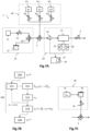
- FIG. 7C is a schematic view of an electronic nose 1 according to an alternative embodiment, which differs from that illustrated on the fig.7A essentially by the fluidic recalibration device 40.
- the fluidic recalibration device 40 is adapted to supply the measuring chamber 21 from the same reservoir 41 of a reference gas associated with a reservoir 43 of a hydrophilic solution, and not from several separate reservoirs.
- the reference gas does not contain target compounds.
- the reservoir 41 contains a reference gas having a non-zero relative humidity ⁇ init . It is connected to the headspace of reservoir 43 which contains a hydrophilic liquid solution, for example a nitric acid ester. The head space is then connected to valve 2, here by a valve 42.
- the reservoir 41 of the relative humidity reference gas ⁇ init may have been filled in the workshop, or alternatively, may have been filled by the electronic nose 1 from humid air from the external environment.
- the tank 41 is connected to the external environment by means of a fluid conduit equipped with a relative humidity sensor (not shown).
- the electronic nose 1 fills the tank 41.
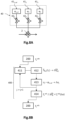
- FIG. 8A is a schematic and partial view of an electronic nose 1 according to another embodiment in which it is configured to carry out a recalibration phase 400.
- the electronic nose 1 is similar to that described in the fig.7A , and is distinguished in particular by the fluidic recalibration device 40.
- FIG. 8B is an example of a method of using the electronic nose, comprising a recalibration phase 400 which is based on a principle similar to that described with reference to the calibration phase 20 illustrated on the fig.5 .
- the characterization phase 200 includes a correction step 240, 250 of the useful signal Su k from a corrective parameter ⁇ S ⁇ k b .
- This corrective parameter is determined from the correction function noted here f k ref0 and determined during the calibration phase 20.
- This calibration phase 20 may have been carried out in the workshop, before the electronic nose 1 is actually put into service.
- the measurement signal S ⁇ k (t) is acquired during the different injection cycles.
- the processing unit determines the reference value S ⁇ k , 1 b associated with the reference gas at ⁇ 1,ref , then determines the reference value S ⁇ k , 2 b associated with the reference gas at ⁇ 2 . It then determines the difference ⁇ S ⁇ k , 2 b between these reference values. The difference in relative humidity is then ⁇ 2 .
- the new correction function f k ref1 is stored in memory 31, and replaces the old function f k ref0 .
- the electronic nose 1 is able to carry out a recalibration phase 400, and thus makes it possible to resolve the sensor drift problem associated with the correction function.
- the fact that the recalibration is online makes it possible to improve the reliability of the electronic nose over long periods of time, and avoids the need for recalibration when returning to the workshop.
- the method of use can then include a new characterization phase 200, which will use the new correction function f k ref1 .
Landscapes
- Physics & Mathematics (AREA)
- Chemical & Material Sciences (AREA)
- General Health & Medical Sciences (AREA)
- General Physics & Mathematics (AREA)
- Pathology (AREA)
- Health & Medical Sciences (AREA)
- Life Sciences & Earth Sciences (AREA)
- Immunology (AREA)
- Analytical Chemistry (AREA)
- Biochemistry (AREA)
- Engineering & Computer Science (AREA)
- Mathematical Physics (AREA)
- Theoretical Computer Science (AREA)
- Spectroscopy & Molecular Physics (AREA)
- Chemical Kinetics & Catalysis (AREA)
- Plasma & Fusion (AREA)
- Investigating Or Analyzing Materials By The Use Of Electric Means (AREA)
- Investigating Or Analysing Materials By Optical Means (AREA)
- Measuring Fluid Pressure (AREA)
- Electrical Control Of Air Or Fuel Supplied To Internal-Combustion Engine (AREA)
Claims (9)
- Verfahren zur Rekalibrierung einer elektronischen Nase (1), die geeignet ist, Zielverbindungen zu charakterisieren, die in einer gasförmigen Probe vorhanden sind, welche in eine Messkammer (21) eingeführt wird, wobei diese mindestens eine empfindliche Stelle (23k) umfasst, die Rezeptoren aufweist, mit denen die Zielverbindungen durch Adsorption/Desorption wechselwirken können, wobei die elektronische Nase (1) eine Verarbeitungseinheit (30) umfasst, in der eine erste Korrekturfunktion (fk ref0, hk ref0) vorgespeichert ist, die eine Änderung eines Parameters, der für das einem Referenzgas zugeordnete Messsignal repräsentativ ist, in Abhängigkeit von einer relativen Feuchtigkeit ausdrückt, wobei das Verfahren die folgenden Schritte umfasst:- aufeinanderfolgende Injektionen (311, 411) von Referenzgasen, die keine Zielverbindungen enthalten, in die Messkammer (21), wobei die nacheinander injizierten Referenzgase vorbestimmte unterschiedliche relative Feuchtigkeitswerte (φ) ungleich Null aufweisen;- Bestimmen (312, 412), im Laufe jeder Injektion, eines Messsignals (Sk(ti)), das für die Wechselwirkungen der Rezeptoren mit dem vorhandenen Referenzgas repräsentativ ist, zu unterschiedlichen Messzeitpunkten als Antwort auf ein Anregungssignal, das im Bereich der empfindlichen Stelle (23k) ausgegeben wird, und anschließend Bestimmen, für jedes Referenzgas, eines Referenzwerts (
 - Bestimmen (314, 414) einer zweiten Korrekturfunktion (fk ref1, hk ref1), die eine Änderung eines Parameters (

- Verfahren zur Rekalibrierung nach Anspruch 1, wobei der Referenzwert (


- Verfahren zur Rekalibrierung nach Anspruch 1 oder 2, wobei der Schritt der aufeinanderfolgenden Injektionen mindestens drei Injektionen unterschiedlicher Referenzgase nacheinander aus unterschiedlichen Behältern (41) umfasst.
- Verfahren zur Rekalibrierung nach Anspruch 1 oder 2, wobei der Schritt der aufeinanderfolgenden Injektionen eine Injektion desselben Referenzgases umfasst, das aus einem Behälter (41) stammt, in dem es einen anfänglichen relativen Feuchtigkeitswert (φinit) aufweist, und bevor es in die Messkammer (21) gelangt, einen Behälter (43) durchläuft, der teilweise mit einer hydrophilen Flüssigkeit gefüllt ist, sodass das in die Messkammer (21) eingeführte Referenzgas eine relative Feuchtigkeit aufweist, die vom anfänglichen Wert (φinit) auf einen Endwert (φf) abnimmt, wobei sie einen Zwischenwert (φint) durchläuft.
- Verfahren zur Rekalibrierung nach Anspruch 1, wobei der Schritt der aufeinanderfolgenden Injektionen mehrere Injektionszyklen umfasst, wobei jeder Zyklus von einer Injektion eines ersten Referenzgases, das eine erste relative Feuchtigkeit (φ)1,ref) aufweist, und einer Injektion unterschiedlicher zweiter Referenzgase, die unterschiedliche zweite relative Feuchtigkeiten (φj) aufweisen, gebildet wird, um mehrere Abweichungen der relativen Feuchtigkeit (Δφj) zwischen jeder zweiten relativen Feuchtigkeit (φj) und der ersten relativen Feuchtigkeit (φ)1,ref) zu erhalten, wobei sich die Abweichungen der relativen Feuchtigkeit (Δφj) voneinander unterscheiden.
- Verfahren zur Rekalibrierung nach Anspruch 5, wobei die elektronische Nase (1) eine erste Quelle (411) für das erste Referenzgas, das eine erste relative Feuchtigkeit (φ)1,ref) aufweist, und unterschiedliche zweite Quellen (41j) für zweite Referenzgase, die die unterschiedlichen zweiten relativen Feuchtigkeiten (φ2) aufweisen, umfasst.
- Verfahren zur Rekalibrierung nach Anspruch 5 oder 6, wobei der Parameter (


- Verfahren zur Verwendung der elektronischen Nase (1), das mehrere Phasen zur Charakterisierung der Zielverbindungen umfasst, darunter eine erste Charakterisierungsphase, die vor einer über das Verfahren nach einem der vorstehenden Ansprüche umgesetzten Rekalibrierung ausgeführt wird, und eine zweite Charakterisierungsphase, die nach der Rekalibrierung ausgeführt wird, wobei jede Charakterisierungsphase die folgenden Schritte umfasst:- Injektion in die Messkammer (21):-- während einer ersten Phase Pa eines Referenzgases, das die Zielverbindungen nicht enthält, und anschließend-- während einer zweiten Phase Pb einer gasförmigen Probe, die die Zielverbindungen umfasst;- Bestimmen, im Laufe des Injektionsschritts, eines Messsignals, das für die Wechselwirkungen der Rezeptoren mit mindestens dem vorhandenen Gas repräsentativ ist, zu unterschiedlichen Messzeitpunkten als Antwort auf ein Anregungssignal, das im Bereich der empfindlichen Stelle ausgegeben wird;- Messen von relativen Feuchtigkeitswerten φ1, φ2 jeweils bei der ersten und der zweiten Phase Pa, Pb in der Messkammer, wobei sich φ2 von φ1 unterscheidet;- Bestimmen eines Korrekturparameters, der der empfindlichen Stelle zugeordnet ist, auf Grundlage mindestens des gemessenen relativen Feuchtigkeitswerts φ2 und einer vorbestimmten Korrekturfunktion (fk, hk), die eine Änderung eines Parameters, der für das dem Referenzgas zugeordnete Messsignal repräsentativ ist, in Abhängigkeit von der relativen Feuchtigkeit ausdrückt;- Bestimmen eines Nutzsignals durch Korrektur des der gasförmigen Probe zugeordneten Messsignals auf Grundlage mindestens des bestimmten Korrekturparameters;- Charakterisieren der Zielverbindungen auf Grundlage des Nutzsignals;- wobei die erste Charakterisierungsphase eine erste vorgespeicherte Korrekturfunktion (fk ref0, hk ref0) verwendet; wobei die Rekalibrierung eine zweite Korrekturfunktion (fk ref1, hk ref1) bestimmt; wobei die zweite Charakterisierungsphase die bestimmte zweite Korrekturfunktion (fk ref1, hk ref1) verwendet.
- Elektronische Nase (1) zur Charakterisierung von Zielverbindungen, die zur Umsetzung des Verfahrens zur Rekalibrierung nach den Ansprüchen 1 bis 7 und des Verfahrens zur Verwendung nach Anspruch 8 geeignet ist, umfassend:- eine Messvorichtung (20), welche umfasst:-- eine Messkammer (21), die geeignet ist, eine gasförmige Probe aufzunehmen, welche zu charakterisierende Verbindungen von Interesse enthält, und mindestens eine empfindliche Stelle (23) umfasst, die Rezeptoren aufweist, mit denen die Zielverbindungen durch Adsorption/Desorption wechselwirken können;-- eine Messeinheit (24, 25), die geeignet ist, ein Messsignal (Sk(ti)), das für die Wechselwirkungen der Rezeptoren mit mindestens dem vorhandenen Gas repräsentativ ist, zu unterschiedlichen Messzeitpunkten als Antwort auf ein Anregungssignal, das im Bereich der empfindlichen Stelle ausgegeben wird, zu bestimmen;-- einen Feuchtigkeitssensor (26), der geeignet ist, relative Feuchtigkeitswerte des in der Messkammer (21) vorhandenen Gases zu messen;- eine strömungstechnische Zuführvorrichtung (10), welche umfasst:-- eine Quelle (11) für ein Referenzgas, die an die Messkammer (21) angeschlossen ist;-- eine Quelle (12) für Zielverbindungen, die an die Messkammer (21) angeschlossen ist, wobei die gasförmige Probe von einem Gas und Zielverbindungen gebildet wird;- eine strömungstechnische Rekalibrierungsvorrichtung (40), die mindestens eine Quelle (41) für mindestens ein Referenzgas umfasst, die geeignet ist, der Messkammer (21) Referenzgase zuzuführen, die unterschiedliche relative Feuchtigkeitswerte aufweisen;- eine Verarbeitungseinheit (30), die geeignet ist:-- einen Korrekturparameter (
 --- mindestens eines Messwerts (φ2) der relativen Feuchtigkeit;--- einer vorbestimmten und der empfindlichen Stelle (23k) zugeordneten Korrekturfunktion (fk, hk), die eine Änderung eines Parameters (
 -- ein Nutzsignal (Suk(ti∈Pb)) durch Korrektur des der gasförmigen Probe zugeordneten Messsignals (Sk(ti∈Pb)) auf Grundlage mindestens des bestimmten Korrekturparameters (
 --die Zielverbindungen auf Grundlage des bestimmten Nutzsignals (Suk(ti∈Pb)) zu charakterisieren;-- die Korrekturfunktion (fk, hk) auf Grundlage der unterschiedlichen relativen Feuchtigkeitswerte des in der Messkammer (21) vorhandenen Referenzgases und der entsprechenden Messsignale (Sk(ti)) zu bestimmen.
Applications Claiming Priority (2)
| Application Number | Priority Date | Filing Date | Title |
|---|---|---|---|
| FR1915729A FR3105832B1 (fr) | 2019-12-30 | 2019-12-30 | Procédé de recalibration d’un nez électronique |
| PCT/EP2020/087942 WO2021136761A1 (fr) | 2019-12-30 | 2020-12-28 | Procede de recalibration d'un nez electronique |
Publications (3)
| Publication Number | Publication Date |
|---|---|
| EP4085244A1 EP4085244A1 (de) | 2022-11-09 |
| EP4085244B1 true EP4085244B1 (de) | 2023-12-27 |
| EP4085244C0 EP4085244C0 (de) | 2023-12-27 |
Family
ID=70614014
Family Applications (1)
| Application Number | Title | Priority Date | Filing Date |
|---|---|---|---|
| EP20839345.4A Active EP4085244B1 (de) | 2019-12-30 | 2020-12-28 | Verfahren zur rekalibrierung einer elektronischen nase |
Country Status (7)
| Country | Link |
|---|---|
| US (1) | US20230031220A1 (de) |
| EP (1) | EP4085244B1 (de) |
| JP (1) | JP2023509657A (de) |
| KR (1) | KR20220119153A (de) |
| CN (1) | CN115176145A (de) |
| FR (1) | FR3105832B1 (de) |
| WO (1) | WO2021136761A1 (de) |
Family Cites Families (4)
| Publication number | Priority date | Publication date | Assignee | Title |
|---|---|---|---|---|
| JP2016090257A (ja) * | 2014-10-30 | 2016-05-23 | シャープ株式会社 | ガス測定装置及びそれを用いたガス測定方法 |
| JP2016138782A (ja) * | 2015-01-27 | 2016-08-04 | シャープ株式会社 | ガス検出装置 |
| FR3046153A1 (fr) | 2015-12-24 | 2017-06-30 | Commissariat Energie Atomique | Systeme presentant une densite surfacique de dispositfs microelectromecaniques et/ou nanoelectromecaniques augmentee |
| FR3063543B1 (fr) | 2017-03-03 | 2022-01-28 | Commissariat Energie Atomique | Procede de calibration d'un nez electronique. |
-
2019
- 2019-12-30 FR FR1915729A patent/FR3105832B1/fr active Active
-
2020
- 2020-12-28 WO PCT/EP2020/087942 patent/WO2021136761A1/fr unknown
- 2020-12-28 KR KR1020227026140A patent/KR20220119153A/ko unknown
- 2020-12-28 CN CN202080097694.9A patent/CN115176145A/zh active Pending
- 2020-12-28 EP EP20839345.4A patent/EP4085244B1/de active Active
- 2020-12-28 US US17/758,291 patent/US20230031220A1/en active Pending
- 2020-12-28 JP JP2022540621A patent/JP2023509657A/ja active Pending
Also Published As
| Publication number | Publication date |
|---|---|
| KR20220119153A (ko) | 2022-08-26 |
| CN115176145A (zh) | 2022-10-11 |
| FR3105832A1 (fr) | 2021-07-02 |
| JP2023509657A (ja) | 2023-03-09 |
| FR3105832B1 (fr) | 2021-12-10 |
| WO2021136761A1 (fr) | 2021-07-08 |
| EP4085244A1 (de) | 2022-11-09 |
| EP4085244C0 (de) | 2023-12-27 |
| US20230031220A1 (en) | 2023-02-02 |
Similar Documents
| Publication | Publication Date | Title |
|---|---|---|
| EP3906402B1 (de) | Verfahren zur charakterisierung von ziel-verbindungen | |
| EP1068510B1 (de) | Verfahren zur wellenlängeneichung einer vorrichtung zur filterung elektromagnetischer strahlung | |
| CA3055115A1 (fr) | Procede de calibration d'un nez electronique | |
| WO2014096287A1 (fr) | Dispositif et procede de discrimination d'un gaz dans un echantillon | |
| EP4065959B1 (de) | Verfahren zum charakterisieren verbindungen in einer messkammer, die eine schwankung der relativen feuchtigkeit aufweist | |
| WO2021023576A1 (fr) | Procédé d'analyse d'un gaz par un capteur optique | |
| EP4085244B1 (de) | Verfahren zur rekalibrierung einer elektronischen nase | |
| WO2021037935A1 (fr) | Méthode et dispositif de caractérisation optique de particules | |
| CA2109568C (fr) | Procede et appareil de dosage spectrophotometrique des liquides aqueux | |
| EP1853898A1 (de) | Verfahren und system zur physikochemischen analyse mittels lasergepulster ablation | |
| EP1938062A1 (de) | Optisches, qualitatives und quantitatives verfahren für die strahlungsspektroskopie | |
| EP3559617B1 (de) | Optimiertes verfahren zur erkennung der bildung von gashydraten | |
| FR3039275B1 (fr) | Dispositif de surveillance d'un produit liquide generant un gaz | |
| EP4305413A1 (de) | Verfahren zur charakterisierung eines analyten in einer gasprobe mit mindestens einer parasitischen chemischen spezies | |
| WO2002097407A1 (fr) | Procede de detection optique d'especes chimiques contenues dans les milieux condenses | |
| WO2023110771A1 (fr) | Procede d'estimation par un nez electronique de l'etat de transformation d'un produit en cours de cuisson | |
| FR2937421A1 (fr) | Determination de la concentration en sel d'une solution aqueuse. | |
| WO2019149530A1 (fr) | Methode de determination d'une vitesse de sedimentation ou de cremage | |
| EP4281756A1 (de) | Verfahren zur kalibrierung eines gassensors und verfahren zur messung eines gases mit der kalibrierung | |
| FR2543687A1 (fr) | Procede et dispositif pour la determination, en continu, de la teneur en l'un de ses constituants, d'un melange eventuellement heterogene | |
| WO2023203033A1 (fr) | Procede de caracterisation d'analytes comportant une variation de temperature au moyen d'un nez electronique de type interferometrique | |
| FR3134183A1 (fr) | Dispositif et procédé de mesure multivariée d’une présence de composés dans un fluide | |
| EP2189750A1 (de) | Verfahren zur Kalibrierung der Verstärkungsfaktoren von Sensorpixeln eines Interferometers |
Legal Events
| Date | Code | Title | Description |
|---|---|---|---|
| STAA | Information on the status of an ep patent application or granted ep patent |
Free format text: STATUS: UNKNOWN |
|
| STAA | Information on the status of an ep patent application or granted ep patent |
Free format text: STATUS: THE INTERNATIONAL PUBLICATION HAS BEEN MADE |
|
| PUAI | Public reference made under article 153(3) epc to a published international application that has entered the european phase |
Free format text: ORIGINAL CODE: 0009012 |
|
| STAA | Information on the status of an ep patent application or granted ep patent |
Free format text: STATUS: REQUEST FOR EXAMINATION WAS MADE |
|
| 17P | Request for examination filed |
Effective date: 20220620 |
|
| AK | Designated contracting states |
Kind code of ref document: A1 Designated state(s): AL AT BE BG CH CY CZ DE DK EE ES FI FR GB GR HR HU IE IS IT LI LT LU LV MC MK MT NL NO PL PT RO RS SE SI SK SM TR |
|
| DAV | Request for validation of the european patent (deleted) | ||
| DAX | Request for extension of the european patent (deleted) | ||
| GRAP | Despatch of communication of intention to grant a patent |
Free format text: ORIGINAL CODE: EPIDOSNIGR1 |
|
| STAA | Information on the status of an ep patent application or granted ep patent |
Free format text: STATUS: GRANT OF PATENT IS INTENDED |
|
| INTG | Intention to grant announced |
Effective date: 20230727 |
|
| GRAS | Grant fee paid |
Free format text: ORIGINAL CODE: EPIDOSNIGR3 |
|
| GRAA | (expected) grant |
Free format text: ORIGINAL CODE: 0009210 |
|
| STAA | Information on the status of an ep patent application or granted ep patent |
Free format text: STATUS: THE PATENT HAS BEEN GRANTED |
|
| AK | Designated contracting states |
Kind code of ref document: B1 Designated state(s): AL AT BE BG CH CY CZ DE DK EE ES FI FR GB GR HR HU IE IS IT LI LT LU LV MC MK MT NL NO PL PT RO RS SE SI SK SM TR |
|
| REG | Reference to a national code |
Ref country code: GB Ref legal event code: FG4D Free format text: NOT ENGLISH |
|
| REG | Reference to a national code |
Ref country code: CH Ref legal event code: EP |
|
| REG | Reference to a national code |
Ref country code: DE Ref legal event code: R096 Ref document number: 602020023570 Country of ref document: DE |
|
| REG | Reference to a national code |
Ref country code: IE Ref legal event code: FG4D Free format text: LANGUAGE OF EP DOCUMENT: FRENCH |
|
| U01 | Request for unitary effect filed |
Effective date: 20240108 |
|
| U07 | Unitary effect registered |
Designated state(s): AT BE BG DE DK EE FI FR IT LT LU LV MT NL PT SE SI Effective date: 20240117 |
|
| PG25 | Lapsed in a contracting state [announced via postgrant information from national office to epo] |
Ref country code: GR Free format text: LAPSE BECAUSE OF FAILURE TO SUBMIT A TRANSLATION OF THE DESCRIPTION OR TO PAY THE FEE WITHIN THE PRESCRIBED TIME-LIMIT Effective date: 20240328 |
|
| PG25 | Lapsed in a contracting state [announced via postgrant information from national office to epo] |
Ref country code: ES Free format text: LAPSE BECAUSE OF FAILURE TO SUBMIT A TRANSLATION OF THE DESCRIPTION OR TO PAY THE FEE WITHIN THE PRESCRIBED TIME-LIMIT Effective date: 20231227 |
|
| PG25 | Lapsed in a contracting state [announced via postgrant information from national office to epo] |
Ref country code: GR Free format text: LAPSE BECAUSE OF FAILURE TO SUBMIT A TRANSLATION OF THE DESCRIPTION OR TO PAY THE FEE WITHIN THE PRESCRIBED TIME-LIMIT Effective date: 20240328 Ref country code: ES Free format text: LAPSE BECAUSE OF FAILURE TO SUBMIT A TRANSLATION OF THE DESCRIPTION OR TO PAY THE FEE WITHIN THE PRESCRIBED TIME-LIMIT Effective date: 20231227 |