EP4085199B1 - Umkehrbares gerotorpumpensystem - Google Patents
Umkehrbares gerotorpumpensystem Download PDFInfo
- Publication number
- EP4085199B1 EP4085199B1 EP20842204.8A EP20842204A EP4085199B1 EP 4085199 B1 EP4085199 B1 EP 4085199B1 EP 20842204 A EP20842204 A EP 20842204A EP 4085199 B1 EP4085199 B1 EP 4085199B1
- Authority
- EP
- European Patent Office
- Prior art keywords
- eccentric ring
- outer rotor
- gerotor pump
- rotor
- inner rotor
- Prior art date
- Legal status (The legal status is an assumption and is not a legal conclusion. Google has not performed a legal analysis and makes no representation as to the accuracy of the status listed.)
- Active
Links
Images


Classifications
-
- F—MECHANICAL ENGINEERING; LIGHTING; HEATING; WEAPONS; BLASTING
- F04—POSITIVE - DISPLACEMENT MACHINES FOR LIQUIDS; PUMPS FOR LIQUIDS OR ELASTIC FLUIDS
- F04C—ROTARY-PISTON, OR OSCILLATING-PISTON, POSITIVE-DISPLACEMENT MACHINES FOR LIQUIDS; ROTARY-PISTON, OR OSCILLATING-PISTON, POSITIVE-DISPLACEMENT PUMPS
- F04C14/00—Control of, monitoring of, or safety arrangements for, machines, pumps or pumping installations
- F04C14/04—Control of, monitoring of, or safety arrangements for, machines, pumps or pumping installations specially adapted for reversible machines or pumps
-
- F—MECHANICAL ENGINEERING; LIGHTING; HEATING; WEAPONS; BLASTING
- F01—MACHINES OR ENGINES IN GENERAL; ENGINE PLANTS IN GENERAL; STEAM ENGINES
- F01C—ROTARY-PISTON OR OSCILLATING-PISTON MACHINES OR ENGINES
- F01C20/00—Control of, monitoring of, or safety arrangements for, machines or engines
- F01C20/04—Control of, monitoring of, or safety arrangements for, machines or engines specially adapted for reversible machines or engines
-
- F—MECHANICAL ENGINEERING; LIGHTING; HEATING; WEAPONS; BLASTING
- F04—POSITIVE - DISPLACEMENT MACHINES FOR LIQUIDS; PUMPS FOR LIQUIDS OR ELASTIC FLUIDS
- F04C—ROTARY-PISTON, OR OSCILLATING-PISTON, POSITIVE-DISPLACEMENT MACHINES FOR LIQUIDS; ROTARY-PISTON, OR OSCILLATING-PISTON, POSITIVE-DISPLACEMENT PUMPS
- F04C15/00—Component parts, details or accessories of machines, pumps or pumping installations, not provided for in groups F04C2/00 - F04C14/00
- F04C15/0057—Driving elements, brakes, couplings, transmission specially adapted for machines or pumps
- F04C15/0061—Means for transmitting movement from the prime mover to driven parts of the pump, e.g. clutches, couplings, transmissions
- F04C15/0065—Means for transmitting movement from the prime mover to driven parts of the pump, e.g. clutches, couplings, transmissions for eccentric movement
-
- F—MECHANICAL ENGINEERING; LIGHTING; HEATING; WEAPONS; BLASTING
- F04—POSITIVE - DISPLACEMENT MACHINES FOR LIQUIDS; PUMPS FOR LIQUIDS OR ELASTIC FLUIDS
- F04C—ROTARY-PISTON, OR OSCILLATING-PISTON, POSITIVE-DISPLACEMENT MACHINES FOR LIQUIDS; ROTARY-PISTON, OR OSCILLATING-PISTON, POSITIVE-DISPLACEMENT PUMPS
- F04C2/00—Rotary-piston machines or pumps
- F04C2/08—Rotary-piston machines or pumps of intermeshing-engagement type, i.e. with engagement of co-operating members similar to that of toothed gearing
- F04C2/10—Rotary-piston machines or pumps of intermeshing-engagement type, i.e. with engagement of co-operating members similar to that of toothed gearing of internal-axis type with the outer member having more teeth or tooth-equivalents, e.g. rollers, than the inner member
- F04C2/102—Rotary-piston machines or pumps of intermeshing-engagement type, i.e. with engagement of co-operating members similar to that of toothed gearing of internal-axis type with the outer member having more teeth or tooth-equivalents, e.g. rollers, than the inner member the two members rotating simultaneously around their respective axes
Definitions
- the present invention relates to a lubrication pump for providing pressurized hydraulic fluid, and more particularly to a reversible gerotor pump system. Exemplary applications include use in a transmission for a heavy duty electric vehicle.
- Reversible gerotor pumps conventionally include an externally toothed inner rotor surrounded by and meshing with an internally toothed outer rotor, both of which rotate together in the same direction about spaced parallel axes.
- the inner rotor generally has one fewer tooth than the outer rotor.
- the shaping of the teeth on the inner and outer rotors is such that as the two rotate together, they produce a pumping action.
- eccentricity reversal is achieved by movement of a reversing ring, also called an eccentric ring, within which the rotor of the pump is mounted.
- the eccentric ring is mounted for rotation about an axis co-extensive with the axis of the inner rotor of the pump and has an eccentrically positioned cylindrical bore within which the cylindrical outer surface of the outer rotor is received.
- the angular position of the reversing ring determines the eccentricity of the rotor relative to the inner rotor and moving the ring relative to the rotor through 180° reverses the eccentricity of the outer rotor relative to the inner rotor.
- the suction port is an important feature of a gerotor pump as it decides the filling capability of cavity and helps to prevent cavitation.
- Meshed teeth of the inner and outer rotors form a region which is called a cavity and the cavity expands in one side and contracts in other side of the housing as rotation of both rotor advances. Multiple cavities are formed between the meshed teeth.
- the cavity expands and accordingly, sucks up the fluid from the suction port; it leaves the suction port when maximum volume reached, and compression starts.
- cavity should not connect discharge and suction ports at the same time to avoid inter-porting losses from higher pressure region of discharge port to lower pressure region of suction port.
- the disclosure provides a reversible gerotor pump to solve the disadvantages and ensure effective reversible rotation operation using the same suction and discharge ports. Further, the reversible gerotor pump is enabled to run at higher operating speed of above 5000 rpm and higher volumetric efficiency of more than 95%.
- the present invention is a reversible gerotor pump system as it is defined in claim 1.
- the reversible gerotor pump system comprises a cylindrical housing comprising a slot of 180 degree along a periphery of the housing, and the slot being defined by a first end at top and a second end at bottom; an eccentric ring positioned within the housing; a locking pin being fixed to the eccentric ring and movably engaged between the first end and the second end in the slot; an outer rotor positioned within the eccentric ring with a radial clearance C2 between the eccentric ring and the outer rotor, the outer rotor being eccentric with the eccentric ring and comprising a plurality of internal teeth with recesses between adjacent teeth; an inner rotor positioned within the outer rotor, the inner rotor comprising a plurality of external teeth, wherein at least a portion of the external teeth of the inner rotor are engaged with at least a portion of the internal teeth of the outer rotor, and the inner rotor and the outer
- the locking pin stops at the first end to stop rotation of the eccentric ring when the shaft rotates in clockwise direction in a first position; when the shaft rotates in reverse direction, the eccentric ring is driven to rotate in counterclockwise rotation direction by contact force between the eccentric ring and the outer rotor; the locking pin stops at the second end to stop rotation of the eccentric ring when the shaft rotates in the counterclockwise direction in a third position; and the suction port and the discharge port respectively function for sucking and discharging a hydraulic fluid unidirectionally in both clockwise and counterclockwise rotation directions.
- the shaft is coupled with the inner rotor with a radial clearance C1 between the shaft and the inner rotor
- the eccentric ring is positioned within the housing with a radial clearance C3 between the eccentric ring and the housing, the inner rotor and the outer rotor are eccentric relative to one another with an inner rotor tip clearance Ci being defined as a radial clearance between a tip of the external teeth and corresponding portion of the outer rotor;
- the eccentric ring is driven to rotate in counterclockwise rotation direction to pass through a second position where the eccentric ring, the inner rotor, and the outer rotor rotate as one part along with the shaft, and the radial clearance C3 is greater than the sum of C1, C2, and Ci in the second position; and the eccentric ring is of convex profile on outer diameter.
- the gerotor can be configured so that the interior diameter contact is present at radial clearances C1 and C2 at the second position.
- the reversible gerotor pump system can further comprise a positive contact system that increases frictional force between an interior side of the eccentric ring and the outer rotor for rotation.
- the plunger can be coated with a Ferritic Nitro-Carburizing (FNC) friction coating.
- FNC Ferritic Nitro-Carburizing
- the cavity is formed by a drill through hole in the eccentric ring with a cap added at the outer diameter of the eccentric ring.
- the positive contact system can be a frictional disc brake type mechanism comprising spring, piston, and pads, and the frictional disc brake system provides spring force to hold the eccentric ring and the outer rotor at the second position, and outlet pressure releases pads and allow the eccentric ring and the outer rotor to rotate freely in the first and third positions.
- the gerotor can be configured so that the locking pin moves in the slot with clearance at both clockwise and counterclockwise directions to provide a self-damping effect to avoid loading impact.
- the gerotor can be configured so that the suction port for the pump can further comprises prolongations at the upstream side and the downstream side.
- the reversible gerotor pump can have a fill speed of above 5000 rpm, and the volumetric efficiency is at least 90% at 5000 rpm.
- a transmission system for vehicles can comprise the reversible gerotor pump system.
- the transmission system can be configured so that the inlet and outlet ports remain as connected and do not need to be reversed when the inner rotor reverses rotation direction.
- the gerotor can be configured in an electric vehicle comprising the transmission system of the present invention.
- the electric vehicle can be a heavy duty truck.
- Reference numerals used in the figures correspond to the following structures: 10-reversible gerotor pump; 11- slot; 11a-first end of slot; 11b- second end of slot; 12- locking pin; 13- eccentric ring; 14- housing; 15- shaft; 16- inner rotor; 17- outer rotor; 18- inlet direction; 18'- direction from inlet to the pump; 19- outlet direction; 20- outer plate; 21a, 21b, 21c - axle center for shaft at different positions; 22a, 22b, 22c - axle center for outer rotor at different positions;
- Reversible gerotor pumps are designed for supplying hydraulic fluid for the vehicle transmission.
- the lubrication pump is expected to support a maximum operating speed of 5000 rpm and 95% volumetric efficiency in a heavy duty electric vehicle automatic 4-speed transmission.
- the conventional design of a gerotor pump provides two symmetric bean shaped ports at the suction and discharge sides, which are symmetric about the x-axis, as in Figure 7 .
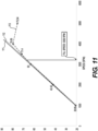
- Research (as shown in Figure 11 ) reveals that the conventional gerotor pump has the fill speed (maximum operating speed) at 3300 rpm and volumetric efficiency at 68%, both of which are less than the critical to quality (CTQ) requirements.
- CTQ critical to quality
- the reversible gerotor pump 10 of the present invention comprises a cylindrical housing 14 with a slot 11 of 180 degree along a periphery of the housing. Slot 11 is defined by a first end 11a at the top and a second end 11b at the bottom.
- An eccentric ring 13 for adjusting eccentricity is positioned within housing 14, and radial clearance C3 is defined between eccentric ring 13 and housing 14.
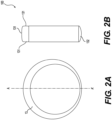
- a locking pin 12 is fixed to the outer periphery of eccentric ring 13 at the thickest portion (along A-A' line in Fig. 2A ) and movably engaged in slot 11 between the first end 11a and the second end 11b in housing 14.
- An outer rotor 17 is positioned within eccentric ring 13, and radial clearance C2 is defined between eccentric ring 13 and outer rotor 17.
- Outer rotor 17 has a plurality of internal teeth 71 with recesses 72 defined between adjacent teeth 71.
- Outer rotor 17 and eccentric ring 13 are located eccentrically.
- An inner rotor 16 is positioned within outer rotor 17.
- Inner rotor 17 comprises a plurality of external teeth 60, where at least a portion of the external teeth 60 of inner rotor 17 are engaged with at least a portion of internal teeth 71 of outer rotor 17 at the recesses 72.
- Inner rotor 16 and outer rotor 17 are eccentric relative to one another.
- An inner rotor tip clearance Ci is defined as a radial clearance between the tip of the external tooth and the moveable portion of the outer rotor corresponding to the external tooth.
- a shaft 15 is coupled with inner rotor 16 for rotatably driving inner rotor 16.
- a radial clearance C1 is defined between shaft 15 and inner rotor 16.
- the plurality of meshed teeth 60 of inner rotor 16 and internal teeth 71 of outer rotor 17 form a plurality of cavities 50 and 50 that expand and contract as they rotate. While rotating, cavity 50 is being expanded and forms a basis for a sucking port and inlet (direction 18 and 18' as shown in Fig. 6 ), and cavity 40 is being contracted and forms a basis for a discharge port and outlet (direction 19 as shown in Fig. 6 ).
- each cavity formed between the external tooth 60 of inner rotor 16 and corresponding recess 72 of outer rotor 17, as illustrated by shaded area 40 on the left side in Fig. 1A decreases in volume, thus creating a pressure to discharge hydraulic fluid in the cavity through outlet.
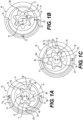
- reversible gerotor pump 10 of the present invention has contact at C1, C2, and C3 shown in Fig. 1A , and axel center 21a of shaft 15 is directly above axel center 22a of outer rotor 17.
- reversible gerotor pump 10 When reversible gerotor pump 10 starts to rotate in the reversal direction, i.e., counterclockwise, it comes to the third position as shown in Fig. 1C through a second position shown in Fig. 1B . As shown in Fig. 1B , reversible gerotor pump 10 is in an intermediate (second) position where there are contact at C1 and C2 and eccentric ring 13, outer rotor 17, and inner rotor 16 rotate as one part with shaft 15. Reversible gerotor pump 10 will pass through the second position when shaft 15 changes rotation direction, such as from clockwise to counterclockwise or from counterclockwise to clockwise.
- eccentric ring 13 When the rotation direction changes, eccentric ring 13 is driven to rotate in the reversed rotating direction by contact force between eccentric ring 13 and outer rotor 17 while locking pin 12 moves along slot 11 until it stops at the second end 11b, the bottom, to stop rotation of eccentric ring 13.
- reversible gerotor pump 10 In the second position, reversible gerotor pump 10 has contact at C1 and C2 as shown in Fig. 1B (axel center 21b of shaft 15 is at the same horizontal line as axel center 22b of outer rotor 17).
- the condition to avoid sticking and achieving interior diameter contact on eccentric ring at C2 during the rotation direction change of shaft 15 is as in formula (3): C3 > ⁇ C1 , C2 , Ci where C1 is the radial clearance between shaft 15 and inner rotor 16 at that position; C2 is the radial clearance between outer rotor 17 and eccentric ring 13 at that position, C3 is the radial clearance between eccentric ring 13 and housing 14 at that position, and Ci is inner rotor tip clearance between the tip of external tooth 60 and corresponding part of the outer rotor.
- reversible gerotor pump 10 comes to the third position in the reversed rotation, i.e., counterclockwise, where eccentric ring 13 comes at the bottom, and shaft 15, along with inner rotor 16 and outer rotor 17, rotates counterclockwise.
- locking pin 12 stops at the bottom, i.e., the second end 11b, and counterclockwise rotation of eccentric ring 13 is stopped, while inner rotor 16 and outer rotor 17 rotate counterclockwise with shaft 15, and directions of inlet 18 and 18', and direction of outlet 19 for suction and discharge are shown, respectively.
- each cavity formed between the external tooth 60 of inner rotor 16 and corresponding recess 72 of outer rotor 17, as illustrated by shaded area 50 on the right side in Fig. 1C increases in volume, thus creating a vacuum and suction force to draw hydraulic liquid into the cavity through the inlet; at the same time, each cavity formed between the external tooth 60 of inner rotor 16 and corresponding recess 72 of outer rotor 17, as illustrated by shaded area 40 on the left side in Fig. 1C , decreases in volume, thus creating a pressure to discharge hydraulic fluid in the cavity through the outlet.
- reversible gerotor pump 10 has contact at C1, C2, and C3 shown in Fig.
- eccentric ring 13 As shown in Fig. 2A , the outer periphery and internal shape of eccentric ring 13 are both cylindrical, however, they are not concentric while the thickness of eccentric ring 13 is distributed symmetrically along A-A' center line.
- the eccentric ring comprises an annulus of material, an inner circumference, and an outer circumference of the annulus, where the two circumferences are not concentric, thereby creating an eccentricity in the thickness of the eccentric ring.
- the thickness of the eccentric ring is uneven but distributed along the periphery of the circumference while symmetrically along the A-A' line.
- Locking pin 12 is fixed to the thickest part of eccentric ring 13. As shown in Fig.
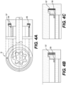
- a positive contact mechanism can be provided to increase the frictional drag between the eccentric ring and rotating rotors and overcome sticking.
- plunger 102 can have Ferritic Nitro-Carburizing (FNC) friction coating which results in higher coefficient ⁇ of the friction.
- FNC coating helps increase static coefficient of friction and reduce tendency of wear.
- a drill through hole with a cap added at the outer diameter of eccentric ring 13 can be used.
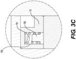
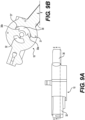
- a frictional disc brake type positive contact mechanism is provided.
- the positive contact system comprises spring, piston, and pads that are arranged on the pump system as in the frictional disc brake system.
- the working mechanism and components of the conventional frictional disc brake system is well known where, based on the Pascal Law, the force applied to the pad is proportional to the area of the pad in the system.
- the frictional disc brake type positive contact system in the present invention further provides added auto release function in addition to the frictional force.
- a frictional disc brake type positive contact mechanism comprises spring 101', piston 104, and pad 105. As shown in Fig.
- the spring may be a Bellvile or wave spring that can be crushed by the fluid pressure and then expand to push the piston to the left and compress the friction discs. Friction discs would have a natural "compliance” whereby they expand when rotating to release grip.
- the locking pin moves within the slot in both directions with clearance.
- clearance in both moving directions D1 and D2 provide self damping effect to avoid impact loading, locking pin 12 moves within the confinement of slot 11.
- the reversible gerotor pump can further comprise a novel design for the suction port with elongations at sides.
- meshed teeth 60 of inner rotor 16 and teeth 71 of outer rotor 17 form regions called cavities 40 and 50, and some cavity expands in one side 50 and contracts in other side 40 of housing 14 as rotation of both rotors advances. Rotation of rotor forms multiple cavities between the rotor teeth.
- the suction port of the reversible gerotor pump decides the filling capability of cavity and helps to prevent cavitation. Further, at any angular position of rotation, the cavity should not connect discharge and suction ports at the same time, and inter-porting losses from the higher pressure region of the discharge port to the lower pressure region of the suction port should be avoided.
- the conventional design of the gerotor pump includes the region in which expansion of cavity takes place and gives the basis to form a suction port 30, and similarly, a discharge port 32 is formed in the following contraction region.
- Suction port 30 and discharge port 32 are symmetric bean shaped ports at the suction and discharge side, respectively.
- the bean shaped suction port 30 includes upstream side 30a and downstream side 30b.
- suction port 30 and the discharge port 32 are symmetric about x-axis.
- suction port 30 of the present invention is provided with prolongations 31 and 31' at both upstream side 30a and downstream side 30b, respectively.
- prolongation 31 at upstream side 30a of suction port 30 is provided to increase cavity filling time when rotor rotates in reverse direction
- prolongation 31' at downstream side 30b of suction port 30 is provided to increase cavity filling time when rotor rotates in clockwise direction.
- Cavity 50' in Fig. 8B shows that the cavity is about to connect to discharge port 32 and leave suction port 30, though the cavity should never connect discharge and suction ports at the same time to avoid inter-porting losses from the higher pressure region of the discharge port to the lower pressure region of the suction port.
- suction port 30 is terminating in the rotation direction of the rotor sets with two prolongations 31 and 31'.
- the shape and dimensions of prolongations 31 and 31' are designed such that suction and discharge ports do not connect to the same captured volume and inter-porting losses from high to low pressure side do not take place.
- Prolongation 31' at downstream side 30b direct more fluid into cavity to fill it substantially.
- Prolongation 31at upstream side 30a of rotor are given for the same purpose when rotor is in reverse direction.
- Figs. 10A to 10F show analysis results for the vapor volume fraction for the conventional gerotor pump and the reversible gerotor pump with the prolongation at the suction port at 0 degree, 30 degree, and 60 degree of rotor rotation at 5000 rpm and 0.5 bar back pressure.
- suction starts at 0 degree and advances in direction of rotation which is captured at 30 degree ( Figs. 10B and 10E ) and 60 degree ( Figs. 10C and 10F ).
- conventional gerotor pump at 5000 rpm, at 0 degree as shown in Fig.
- the low pressure regions form at the upstream side on the right due to expansion of the cavity before suction port, and vapor fraction is carried from suction port as shown by the 3 large areas on the left; at 30 degree as shown in Fig. 10B , vapor intensity in the cavity at upstream side in Fig. 10A is getting reduced as it exposes to higher pressure fluid at suction port, while at the downstream side, vapor fraction is carried from suction port as seen at the upper portion of Fig. 10B ; at 60 degree as shown in Fig. 10C , vapor formation can be seen at the downstream side of the suction port (right side) due to insufficient cavity filling, while on left side, a large vapor fraction is carried from the suction port to the discharge port.
- the vapor fraction also increases because of insufficient filling, i.e., vapor at the discharge side is carried from the suction port (but it is not generated at the discharge port).
- the prolongations on the suction port of the reversible gerotor pump system may be manufactured in all sizes of reversible gerotor pumps to improve the volumetric efficiency and maximum operating speed.
- the suction port of the reversible gerotor pump system can be implemented on any lubrication pump. It is beneficial in the transmission system for vehicles and is particularly useful for medium and heavy-duty electric vehicle transmissions, as an example.
- the reversible gerotor pump can be used in other applications than vehicle transmissions. It is easily manufacturable since High Pressure Die Casting (HPDC) is used to manufacture the pump housing.
- HPDC High Pressure Die Casting
- suction port meets all technology feasibility, manufacturability, and cost aspects.
- a transmission system for vehicles can comprise the reversible gerotor pump system of the present invention.
- the reversible gerotor pump system can be used for supplying hydraulic fluid in the transmission system of any vehicles and is particularly useful in the transmission system for medium and heavy-duty electric vehicles.
- An electric vehicle can comprising the transmission system disclosed herein.
- the electric vehicle can be a heavy duty truck.
Landscapes
- Engineering & Computer Science (AREA)
- Mechanical Engineering (AREA)
- General Engineering & Computer Science (AREA)
- Rotary Pumps (AREA)
- Details And Applications Of Rotary Liquid Pumps (AREA)
Claims (14)
- Umkehrbares Gerotorpumpensystem, umfassendein zylindrisches Gehäuse (14), das einen Schlitz (11) von 180 Grad entlang eines Umfangs des Gehäuses umfasst, wobei der Schlitz durch ein erstes Ende (11a) an der Oberseite und ein zweites Ende (11b) an der Unterseite definiert ist,einen exzentrischen Ring (13), der innerhalb des Gehäuses (14) angeordnet ist, einen Verriegelungsstift (12), der an dem exzentrischen Ring (13) befestigt ist und beweglich zwischen dem ersten Ende (11a) und dem zweiten Ende (11b) in den Schlitz (11) eingreift,einen Außenrotor (17), der innerhalb des exzentrischen Rings (13) mit einem radialen Spiel C2 zwischen dem exzentrischen Ring und dem Außenrotor positioniert ist, wobei der Außenrotor exzentrisch mit dem exzentrischen Ring ist und eine Vielzahl von Innenzähnen (71) mit Aussparungen (72) zwischen benachbarten Zähnen umfasst,einen Innenrotor (16), der innerhalb des Außenrotors (17) angeordnet ist, wobei der Innenrotor eine Vielzahl von Außenzähnen (60) umfasst, wobei mindestens ein Abschnitt der Außenzähne des Innenrotors mit mindestens einem Abschnitt der Innenzähne (71) des Außenrotors in Eingriff steht, und der Innenrotor und der Außenrotor relativ zueinander exzentrisch sind, und wobei die Vielzahl von ineinandergreifenden Zähnen des Innenrotors und des Außenrotors eine Vielzahl von Hohlräumen (50, 50') bildet, die sich ausdehnen und zusammenziehen, wenn sich die Welle (15), der Innenrotor und der Außenrotor drehen;eine Welle (15), die mit dem Innenrotor (16) gekoppelt ist, um den Innenrotor drehend anzutreiben,eine Ansaugöffnung (30) zum Bereitstellen von Hydraulikfluid für den sich ausdehnenden Hohlraum (50, 50'), wobei die Ansaugöffnung eine stromaufwärtige Seite (30a) und eine stromabwärtige Seite (30b) umfasst,und eine Ablassöffnung (32) zum Ablassen von Hydraulikfluid aus dem sich zusammenziehenden Hohlraum (50, 50'),wobei der Verriegelungsstift (12) an dem ersten Ende (11a) stoppt, um die Drehung des exzentrischen Rings (13) zu stoppen, wenn sich die Welle (15) in einer erstenPosition im Uhrzeigersinn dreht;wobei, wenn sich die Welle (15) in umgekehrter Richtung dreht, der exzentrische Ring (13) durch die Kontaktkraft zwischen dem exzentrischen Ring und dem Außenrotor (17) angetrieben wird, sich gegen den Uhrzeigersinn zu drehen;wobei der Verriegelungsstift (12) an dem zweiten Ende (11b) stoppt und die Drehung des exzentrischen Rings (13) stoppt, wenn sich die Welle (15) in einer dritten Position gegen den Uhrzeigersinn dreht; undwobei die Ansaugöffnung (30) und die Ablassöffnung (32) jeweils zum Ansaugen und Ablassen eines Hydraulikfluids unidirektional sowohl im Uhrzeigersinn als auch gegen diesen funktionieren;dadurch gekennzeichnet, dassdie Welle (15) mit dem Innenrotor (16) mit einem radialen Spiel C1 zwischen der Welle und dem Innenrotor gekoppelt ist,der exzentrische Ring (13) innerhalb des Gehäuses (14) mit einem radialen Spiel C3 zwischen dem exzentrischen Ring und dem Gehäuse angeordnet ist,der Innenrotor und der Außenrotor relativ zueinander exzentrisch sind, wobei ein Innenrotorspitzenspiel Ci als ein radiales Spiel zwischen einer Spitze der Außenzähne und einem entsprechenden Abschnitt des Außenrotors definiert ist; wobei, wenn sich die Welle (15) in umgekehrter Richtung dreht, der exzentrische Ring (13) durch die Kontaktkraft zwischen dem exzentrischen Ring und dem Innenrotor (16) angetrieben wird, sich gegen den Uhrzeigersinn dreht und eine zweite Position durchläuft, in der sich der exzentrische Ring, der Innenrotor und der Außenrotor als ein Teil zusammen mit der Welle drehen, und wobei das radiale Spiel C3 größer ist als die Summe von C1, C2 und Ci in der zweiten Position; undwobei der exzentrische Ring (13) ein konvexes Profil am Außendurchmesser hat.
- Umkehrbares Gerotorpumpensystem nach Anspruch 1, wobei ein Kontakt des Innendurchmessers bei radialen Spielen C1 und C2 an der zweiten Position vorhanden ist.
- Umkehrbares Gerotorpumpensystem nach Anspruch 1, das ferner Folgendes umfasstein positives Kontaktsystem,wobei das positive Kontaktsystem die Reibungskraft zwischen einer Innenseite des exzentrischen Rings (13) und dem Außenrotor (17) zum Drehen erhöht.
- Umkehrbares Gerotorpumpensystem nach Anspruch 3, wobei das positive Kontaktsystem (100) Folgendes umfassteinen Hohlraum an der Innenseite des exzentrischen Rings (13),eine Feder (101) innerhalb des Hohlraums (103) in einem konstant komprimierten Zustand, und einen Kolben (102) innerhalb des Hohlraums (103), der konstant von der Feder gedrückt wird,wobei die Kompression der Feder (101) über den Kolben (102) eine Last N auf den Außenrotor (17) ausübt, µ in der Reibungskraft F' nach der Formel F' = µ*N ein Koeffizient des Reibungskontakts ist und wobei F' den exzentrischen Ring (13) mit dem Außenrotor und dem Innenrotor (16) während des Drehrichtungswechsels antreibt und dreht.
- Umkehrbares Gerotorpumpensystem nach Anspruch 5, wobei der Kolben (102) mit einer ferritischen Nitro-Carburizing (FNC)-Reibungsschicht beschichtet ist.
- Umkehrbares Gerotorpumpensystem nach Anspruch 5, wobei der Hohlraum (103) durch eine Durchgangsbohrung im exzentrischen Ring mit einer am Außendurchmesser des exzentrischen Rings hinzugefügten Kappe gebildet wird.
- Umkehrbares Gerotorpumpensystem nach Anspruch 3, wobei das positive Kontaktsystem ein Mechanismus vom Typ Reibungsscheibenbremse ist, der eine Feder (101'), einen Kolben (104) und Bremsbeläge (105) umfasst, und das Reibungsscheiben-Bremssystem eine Federkraft bereitstellt, die den exzentrischen Ring (103) und den Außenrotor (17) in der zweiten Position hält, und wobei der Auslassdruck die Bremsbeläge freigibt und es dem exzentrischen Ring und dem Außenrotor ermöglicht, sich in der ersten und dritten Position frei zu drehen.
- Umkehrbares Gerotorpumpensystem nach Anspruch 1, wobei sich der Verriegelungsstift (12) sowohl im Uhrzeigersinn als auch gegen den Uhrzeigersinn mit Spiel in dem Schlitz (11) bewegt und so einen Selbstdämpfungseffekt zur Vermeidung von Belastungsstößen bereitstellt.
- Umkehrbares Gerotorpumpensystem nach Anspruch 1, das ferner Folgendes umfasstVerlängerungen (31, 31') an der Ansaugöffnung (30) an der stromaufwärtigen Seite (30a) und der stromabwärtigen Seite (30b),wobei die Verlängerungen (31, 31') die Füllzeit der Hohlräume (50, 50') erhöhen, wenn sich das umkehrbare Gerotorpumpensystem dreht.
- Umkehrbares Gerotorpumpensystem nach Anspruch 9, wobei die Füllgeschwindigkeit über 5000 U/min liegt.
- Umkehrbares Gerotorpumpensystem nach Anspruch 10, wobei der volumetrische Wirkungsgrad bei 5000 U/min mindestens 90 % beträgt.
- Getriebesystem für Fahrzeuge, umfassend das umkehrbare Gerotorpumpensystem nach Anspruch 1.
- Elektrofahrzeug, umfassend das Getriebesystem nach Anspruch 12.
- Elektrofahrzeug nach Anspruch 13, wobei das Elektrofahrzeug ein Schwerlastkraftwagen ist.
Applications Claiming Priority (3)
| Application Number | Priority Date | Filing Date | Title |
|---|---|---|---|
| IN201911054619 | 2019-12-31 | ||
| IN202011049065 | 2020-11-10 | ||
| PCT/EP2020/025602 WO2021136589A1 (en) | 2019-12-31 | 2020-12-30 | Reversible gerotor pump system |
Publications (2)
| Publication Number | Publication Date |
|---|---|
| EP4085199A1 EP4085199A1 (de) | 2022-11-09 |
| EP4085199B1 true EP4085199B1 (de) | 2025-01-29 |
Family
ID=74186626
Family Applications (1)
| Application Number | Title | Priority Date | Filing Date |
|---|---|---|---|
| EP20842204.8A Active EP4085199B1 (de) | 2019-12-31 | 2020-12-30 | Umkehrbares gerotorpumpensystem |
Country Status (4)
| Country | Link |
|---|---|
| US (1) | US11859614B2 (de) |
| EP (1) | EP4085199B1 (de) |
| CN (1) | CN115003912B (de) |
| WO (1) | WO2021136589A1 (de) |
Families Citing this family (4)
| Publication number | Priority date | Publication date | Assignee | Title |
|---|---|---|---|---|
| CN115523135A (zh) * | 2022-10-13 | 2022-12-27 | 滁州市经纬装备科技有限公司 | 一种嵌入式摆线齿轮泵 |
| CN115559897A (zh) * | 2022-10-13 | 2023-01-03 | 滁州市经纬装备科技有限公司 | 一种电动滑油泵 |
| CN116591951A (zh) * | 2023-06-26 | 2023-08-15 | 太重榆液长治液压有限公司 | 带液压阀的可逆摆线泵 |
| CN117703746B (zh) * | 2024-01-16 | 2024-08-09 | 南京孚奥智能技术有限公司 | 内啮合齿轮泵 |
Family Cites Families (14)
| Publication number | Priority date | Publication date | Assignee | Title |
|---|---|---|---|---|
| US2458678A (en) * | 1945-06-02 | 1949-01-11 | Eaton Mfg Co | Unidirectional flow gear pump |
| DE1553281A1 (de) * | 1963-04-30 | 1969-09-25 | Zahnradfabrik Friedrichshafen | Kapselwerk,insbesondere Raederkapselwerk |
| DE2742821C2 (de) | 1977-09-23 | 1982-11-25 | Zahnradfabrik Friedrichshafen Ag, 7990 Friedrichshafen | Zahnradpumpe mit bei wechselnder Antriebsrichtung gleichbleibender Förderrichtung |
| US4171192A (en) | 1978-05-05 | 1979-10-16 | Thermo King Corporation | Eccentric positioning means for a reversible pump |
| US4222719A (en) | 1979-01-02 | 1980-09-16 | Thermo King Corporation | Reversible unidirectional fluid flow pump |
| GB2215401B (en) | 1988-02-26 | 1992-04-15 | Concentric Pumps Ltd | Gerotor pumps |
| US5702319A (en) * | 1995-10-13 | 1997-12-30 | Dana Corporation | Hydromechanical system for limiting differential speed between differentially rotating members |
| US5711408A (en) | 1996-05-09 | 1998-01-27 | Dana Corporation | Reversible gerotor pump |
| GB2342396B (en) | 1998-08-15 | 2002-04-24 | Lucas Ind Plc | Pumps |
| JP2006046283A (ja) | 2004-08-09 | 2006-02-16 | Hitachi Ltd | 内接式歯車ポンプ |
| US7922468B2 (en) * | 2005-06-22 | 2011-04-12 | Magna Powertrain, Inc. | Gear pump with improved inlet port |
| DE102013110400A1 (de) | 2013-09-20 | 2015-03-26 | Getrag Getriebe- Und Zahnradfabrik Hermann Hagenmeyer Gmbh & Cie Kg | Innenzahnradpumpe und Hydraulikkreis für Kraftfahrzeugantriebsstrang |
| US20190017161A1 (en) * | 2017-07-14 | 2019-01-17 | GM Global Technology Operations LLC | Ferritic nitrocarburized vehicle component and methods of making and using the same |
| US10895257B2 (en) | 2018-02-13 | 2021-01-19 | GM Global Technology Operations LLC | Lubrication strategy for dry run pump system |
-
2020
- 2020-12-30 EP EP20842204.8A patent/EP4085199B1/de active Active
- 2020-12-30 US US17/758,192 patent/US11859614B2/en active Active
- 2020-12-30 WO PCT/EP2020/025602 patent/WO2021136589A1/en not_active Ceased
- 2020-12-30 CN CN202080094094.7A patent/CN115003912B/zh active Active
Also Published As
| Publication number | Publication date |
|---|---|
| CN115003912B (zh) | 2024-03-01 |
| US20230022514A1 (en) | 2023-01-26 |
| WO2021136589A1 (en) | 2021-07-08 |
| CN115003912A (zh) | 2022-09-02 |
| US11859614B2 (en) | 2024-01-02 |
| EP4085199A1 (de) | 2022-11-09 |
Similar Documents
| Publication | Publication Date | Title |
|---|---|---|
| EP4085199B1 (de) | Umkehrbares gerotorpumpensystem | |
| JP5640075B2 (ja) | 油圧装置に用いられる軸受、油圧変換機、および油圧駆動システムを有する車両 | |
| US5711408A (en) | Reversible gerotor pump | |
| US7832996B2 (en) | Hydrostatic rotary cylinder engine | |
| US10184471B2 (en) | Trochoid pump for transferring high-viscosity liquid under high pressure | |
| US6332522B1 (en) | Hydraulic coupling for vehicle drivetrain | |
| JPH10502715A (ja) | はすば歯車ポンプまたはモーター | |
| US20140020662A1 (en) | Vehicle oil pump | |
| CN1188599C (zh) | 反向啮合式转子组 | |
| US5890885A (en) | Filling member-less internal-gear pump having a sealed running ring | |
| KR20170093218A (ko) | 제로터 펌프 | |
| JP7124954B2 (ja) | はすば歯車ポンプまたはモータ | |
| KR100435686B1 (ko) | 무단 변속기용 오일 펌프 | |
| CN109737052B (zh) | 一种齿轮泵 | |
| JP2009228642A (ja) | オイルポンプ | |
| JP2005076542A (ja) | 歯車ポンプおよびこれを用いた自動変速機用オイルポンプ | |
| CN115163442B (zh) | 缸体、柱塞泵及马达 | |
| CN220979844U (zh) | 一种新型摆线齿轮及摆线齿轮泵 | |
| CN218509707U (zh) | 汽车用油泵中的改进型齿轮 | |
| JP3194044B2 (ja) | オイルポンプの構造 | |
| CN118273947A (zh) | 内啮合齿轮泵、集成式电机泵和车辆 | |
| US6524087B1 (en) | Hydrostatic planetary rotation machine having an orbiting rotary valve | |
| CN103671091B (zh) | 一种强化齿轮端面动压润滑效应的外啮合齿轮泵 | |
| JP7014093B2 (ja) | 歯車ポンプまたはモータ | |
| JPH1113642A (ja) | 歯車ポンプ |
Legal Events
| Date | Code | Title | Description |
|---|---|---|---|
| STAA | Information on the status of an ep patent application or granted ep patent |
Free format text: STATUS: UNKNOWN |
|
| STAA | Information on the status of an ep patent application or granted ep patent |
Free format text: STATUS: THE INTERNATIONAL PUBLICATION HAS BEEN MADE |
|
| PUAI | Public reference made under article 153(3) epc to a published international application that has entered the european phase |
Free format text: ORIGINAL CODE: 0009012 |
|
| STAA | Information on the status of an ep patent application or granted ep patent |
Free format text: STATUS: REQUEST FOR EXAMINATION WAS MADE |
|
| 17P | Request for examination filed |
Effective date: 20220715 |
|
| AK | Designated contracting states |
Kind code of ref document: A1 Designated state(s): AL AT BE BG CH CY CZ DE DK EE ES FI FR GB GR HR HU IE IS IT LI LT LU LV MC MK MT NL NO PL PT RO RS SE SI SK SM TR |
|
| DAV | Request for validation of the european patent (deleted) | ||
| DAX | Request for extension of the european patent (deleted) | ||
| P01 | Opt-out of the competence of the unified patent court (upc) registered |
Effective date: 20230521 |
|
| GRAP | Despatch of communication of intention to grant a patent |
Free format text: ORIGINAL CODE: EPIDOSNIGR1 |
|
| STAA | Information on the status of an ep patent application or granted ep patent |
Free format text: STATUS: GRANT OF PATENT IS INTENDED |
|
| INTG | Intention to grant announced |
Effective date: 20240820 |
|
| GRAS | Grant fee paid |
Free format text: ORIGINAL CODE: EPIDOSNIGR3 |
|
| GRAA | (expected) grant |
Free format text: ORIGINAL CODE: 0009210 |
|
| STAA | Information on the status of an ep patent application or granted ep patent |
Free format text: STATUS: THE PATENT HAS BEEN GRANTED |
|
| AK | Designated contracting states |
Kind code of ref document: B1 Designated state(s): AL AT BE BG CH CY CZ DE DK EE ES FI FR GB GR HR HU IE IS IT LI LT LU LV MC MK MT NL NO PL PT RO RS SE SI SK SM TR |
|
| REG | Reference to a national code |
Ref country code: GB Ref legal event code: FG4D |
|
| REG | Reference to a national code |
Ref country code: CH Ref legal event code: EP |
|
| REG | Reference to a national code |
Ref country code: DE Ref legal event code: R096 Ref document number: 602020045603 Country of ref document: DE |
|
| REG | Reference to a national code |
Ref country code: IE Ref legal event code: FG4D |
|
| REG | Reference to a national code |
Ref country code: NL Ref legal event code: MP Effective date: 20250129 |
|
| PG25 | Lapsed in a contracting state [announced via postgrant information from national office to epo] |
Ref country code: NL Free format text: LAPSE BECAUSE OF FAILURE TO SUBMIT A TRANSLATION OF THE DESCRIPTION OR TO PAY THE FEE WITHIN THE PRESCRIBED TIME-LIMIT Effective date: 20250129 |
|
| PG25 | Lapsed in a contracting state [announced via postgrant information from national office to epo] |
Ref country code: RS Free format text: LAPSE BECAUSE OF FAILURE TO SUBMIT A TRANSLATION OF THE DESCRIPTION OR TO PAY THE FEE WITHIN THE PRESCRIBED TIME-LIMIT Effective date: 20250429 |
|
| PG25 | Lapsed in a contracting state [announced via postgrant information from national office to epo] |
Ref country code: FI Free format text: LAPSE BECAUSE OF FAILURE TO SUBMIT A TRANSLATION OF THE DESCRIPTION OR TO PAY THE FEE WITHIN THE PRESCRIBED TIME-LIMIT Effective date: 20250129 |
|
| PG25 | Lapsed in a contracting state [announced via postgrant information from national office to epo] |
Ref country code: PL Free format text: LAPSE BECAUSE OF FAILURE TO SUBMIT A TRANSLATION OF THE DESCRIPTION OR TO PAY THE FEE WITHIN THE PRESCRIBED TIME-LIMIT Effective date: 20250129 |
|
| PG25 | Lapsed in a contracting state [announced via postgrant information from national office to epo] |
Ref country code: ES Free format text: LAPSE BECAUSE OF FAILURE TO SUBMIT A TRANSLATION OF THE DESCRIPTION OR TO PAY THE FEE WITHIN THE PRESCRIBED TIME-LIMIT Effective date: 20250129 |
|
| REG | Reference to a national code |
Ref country code: LT Ref legal event code: MG9D |
|
| PG25 | Lapsed in a contracting state [announced via postgrant information from national office to epo] |
Ref country code: IS Free format text: LAPSE BECAUSE OF FAILURE TO SUBMIT A TRANSLATION OF THE DESCRIPTION OR TO PAY THE FEE WITHIN THE PRESCRIBED TIME-LIMIT Effective date: 20250529 Ref country code: NO Free format text: LAPSE BECAUSE OF FAILURE TO SUBMIT A TRANSLATION OF THE DESCRIPTION OR TO PAY THE FEE WITHIN THE PRESCRIBED TIME-LIMIT Effective date: 20250429 |
|
| REG | Reference to a national code |
Ref country code: AT Ref legal event code: MK05 Ref document number: 1763680 Country of ref document: AT Kind code of ref document: T Effective date: 20250129 |
|
| PG25 | Lapsed in a contracting state [announced via postgrant information from national office to epo] |
Ref country code: HR Free format text: LAPSE BECAUSE OF FAILURE TO SUBMIT A TRANSLATION OF THE DESCRIPTION OR TO PAY THE FEE WITHIN THE PRESCRIBED TIME-LIMIT Effective date: 20250129 |
|
| PG25 | Lapsed in a contracting state [announced via postgrant information from national office to epo] |
Ref country code: LV Free format text: LAPSE BECAUSE OF FAILURE TO SUBMIT A TRANSLATION OF THE DESCRIPTION OR TO PAY THE FEE WITHIN THE PRESCRIBED TIME-LIMIT Effective date: 20250129 Ref country code: PT Free format text: LAPSE BECAUSE OF FAILURE TO SUBMIT A TRANSLATION OF THE DESCRIPTION OR TO PAY THE FEE WITHIN THE PRESCRIBED TIME-LIMIT Effective date: 20250529 |
|
| PG25 | Lapsed in a contracting state [announced via postgrant information from national office to epo] |
Ref country code: GR Free format text: LAPSE BECAUSE OF FAILURE TO SUBMIT A TRANSLATION OF THE DESCRIPTION OR TO PAY THE FEE WITHIN THE PRESCRIBED TIME-LIMIT Effective date: 20250430 Ref country code: BG Free format text: LAPSE BECAUSE OF FAILURE TO SUBMIT A TRANSLATION OF THE DESCRIPTION OR TO PAY THE FEE WITHIN THE PRESCRIBED TIME-LIMIT Effective date: 20250129 |
|
| PG25 | Lapsed in a contracting state [announced via postgrant information from national office to epo] |
Ref country code: AT Free format text: LAPSE BECAUSE OF FAILURE TO SUBMIT A TRANSLATION OF THE DESCRIPTION OR TO PAY THE FEE WITHIN THE PRESCRIBED TIME-LIMIT Effective date: 20250129 |
|
| PG25 | Lapsed in a contracting state [announced via postgrant information from national office to epo] |
Ref country code: SE Free format text: LAPSE BECAUSE OF FAILURE TO SUBMIT A TRANSLATION OF THE DESCRIPTION OR TO PAY THE FEE WITHIN THE PRESCRIBED TIME-LIMIT Effective date: 20250129 |
|
| PG25 | Lapsed in a contracting state [announced via postgrant information from national office to epo] |
Ref country code: SM Free format text: LAPSE BECAUSE OF FAILURE TO SUBMIT A TRANSLATION OF THE DESCRIPTION OR TO PAY THE FEE WITHIN THE PRESCRIBED TIME-LIMIT Effective date: 20250129 |
|
| PG25 | Lapsed in a contracting state [announced via postgrant information from national office to epo] |
Ref country code: DK Free format text: LAPSE BECAUSE OF FAILURE TO SUBMIT A TRANSLATION OF THE DESCRIPTION OR TO PAY THE FEE WITHIN THE PRESCRIBED TIME-LIMIT Effective date: 20250129 |
|
| PG25 | Lapsed in a contracting state [announced via postgrant information from national office to epo] |
Ref country code: IT Free format text: LAPSE BECAUSE OF FAILURE TO SUBMIT A TRANSLATION OF THE DESCRIPTION OR TO PAY THE FEE WITHIN THE PRESCRIBED TIME-LIMIT Effective date: 20250129 |
|
| PG25 | Lapsed in a contracting state [announced via postgrant information from national office to epo] |
Ref country code: EE Free format text: LAPSE BECAUSE OF FAILURE TO SUBMIT A TRANSLATION OF THE DESCRIPTION OR TO PAY THE FEE WITHIN THE PRESCRIBED TIME-LIMIT Effective date: 20250129 Ref country code: CZ Free format text: LAPSE BECAUSE OF FAILURE TO SUBMIT A TRANSLATION OF THE DESCRIPTION OR TO PAY THE FEE WITHIN THE PRESCRIBED TIME-LIMIT Effective date: 20250129 |
|
| PG25 | Lapsed in a contracting state [announced via postgrant information from national office to epo] |
Ref country code: RO Free format text: LAPSE BECAUSE OF FAILURE TO SUBMIT A TRANSLATION OF THE DESCRIPTION OR TO PAY THE FEE WITHIN THE PRESCRIBED TIME-LIMIT Effective date: 20250129 |
|
| PG25 | Lapsed in a contracting state [announced via postgrant information from national office to epo] |
Ref country code: SK Free format text: LAPSE BECAUSE OF FAILURE TO SUBMIT A TRANSLATION OF THE DESCRIPTION OR TO PAY THE FEE WITHIN THE PRESCRIBED TIME-LIMIT Effective date: 20250129 |
|
| REG | Reference to a national code |
Ref country code: DE Ref legal event code: R097 Ref document number: 602020045603 Country of ref document: DE |
|
| PLBE | No opposition filed within time limit |
Free format text: ORIGINAL CODE: 0009261 |
|
| STAA | Information on the status of an ep patent application or granted ep patent |
Free format text: STATUS: NO OPPOSITION FILED WITHIN TIME LIMIT |
|
| 26N | No opposition filed |
Effective date: 20251030 |
|
| PGFP | Annual fee paid to national office [announced via postgrant information from national office to epo] |
Ref country code: DE Payment date: 20251126 Year of fee payment: 6 |
|
| PGFP | Annual fee paid to national office [announced via postgrant information from national office to epo] |
Ref country code: GB Payment date: 20251120 Year of fee payment: 6 |
|
| PGFP | Annual fee paid to national office [announced via postgrant information from national office to epo] |
Ref country code: FR Payment date: 20251120 Year of fee payment: 6 |