EP4083634A1 - Automatic sample feeding system, sample analysis system and method for automatic sample feeding control - Google Patents
Automatic sample feeding system, sample analysis system and method for automatic sample feeding control Download PDFInfo
- Publication number
- EP4083634A1 EP4083634A1 EP19957638.0A EP19957638A EP4083634A1 EP 4083634 A1 EP4083634 A1 EP 4083634A1 EP 19957638 A EP19957638 A EP 19957638A EP 4083634 A1 EP4083634 A1 EP 4083634A1
- Authority
- EP
- European Patent Office
- Prior art keywords
- sample
- sample rack
- region
- rack
- move
- Prior art date
- Legal status (The legal status is an assumption and is not a legal conclusion. Google has not performed a legal analysis and makes no representation as to the accuracy of the status listed.)
- Granted
Links
Images




Classifications
-
- G—PHYSICS
- G01—MEASURING; TESTING
- G01N—INVESTIGATING OR ANALYSING MATERIALS BY DETERMINING THEIR CHEMICAL OR PHYSICAL PROPERTIES
- G01N35/00—Automatic analysis not limited to methods or materials provided for in any single one of groups G01N1/00 - G01N33/00; Handling materials therefor
- G01N35/02—Automatic analysis not limited to methods or materials provided for in any single one of groups G01N1/00 - G01N33/00; Handling materials therefor using a plurality of sample containers moved by a conveyor system past one or more treatment or analysis stations
- G01N35/04—Details of the conveyor system
-
- G—PHYSICS
- G01—MEASURING; TESTING
- G01N—INVESTIGATING OR ANALYSING MATERIALS BY DETERMINING THEIR CHEMICAL OR PHYSICAL PROPERTIES
- G01N35/00—Automatic analysis not limited to methods or materials provided for in any single one of groups G01N1/00 - G01N33/00; Handling materials therefor
- G01N35/00584—Control arrangements for automatic analysers
- G01N35/00594—Quality control, including calibration or testing of components of the analyser
- G01N35/00603—Reinspection of samples
-
- G—PHYSICS
- G01—MEASURING; TESTING
- G01N—INVESTIGATING OR ANALYSING MATERIALS BY DETERMINING THEIR CHEMICAL OR PHYSICAL PROPERTIES
- G01N35/00—Automatic analysis not limited to methods or materials provided for in any single one of groups G01N1/00 - G01N33/00; Handling materials therefor
- G01N35/02—Automatic analysis not limited to methods or materials provided for in any single one of groups G01N1/00 - G01N33/00; Handling materials therefor using a plurality of sample containers moved by a conveyor system past one or more treatment or analysis stations
- G01N35/026—Automatic analysis not limited to methods or materials provided for in any single one of groups G01N1/00 - G01N33/00; Handling materials therefor using a plurality of sample containers moved by a conveyor system past one or more treatment or analysis stations having blocks or racks of reaction cells or cuvettes
-
- G—PHYSICS
- G01—MEASURING; TESTING
- G01N—INVESTIGATING OR ANALYSING MATERIALS BY DETERMINING THEIR CHEMICAL OR PHYSICAL PROPERTIES
- G01N35/00—Automatic analysis not limited to methods or materials provided for in any single one of groups G01N1/00 - G01N33/00; Handling materials therefor
- G01N35/02—Automatic analysis not limited to methods or materials provided for in any single one of groups G01N1/00 - G01N33/00; Handling materials therefor using a plurality of sample containers moved by a conveyor system past one or more treatment or analysis stations
- G01N35/04—Details of the conveyor system
- G01N2035/0401—Sample carriers, cuvettes or reaction vessels
- G01N2035/0412—Block or rack elements with a single row of samples
- G01N2035/0415—Block or rack elements with a single row of samples moving in two dimensions in a horizontal plane
-
- G—PHYSICS
- G01—MEASURING; TESTING
- G01N—INVESTIGATING OR ANALYSING MATERIALS BY DETERMINING THEIR CHEMICAL OR PHYSICAL PROPERTIES
- G01N35/00—Automatic analysis not limited to methods or materials provided for in any single one of groups G01N1/00 - G01N33/00; Handling materials therefor
- G01N35/02—Automatic analysis not limited to methods or materials provided for in any single one of groups G01N1/00 - G01N33/00; Handling materials therefor using a plurality of sample containers moved by a conveyor system past one or more treatment or analysis stations
- G01N35/04—Details of the conveyor system
- G01N2035/046—General conveyor features
- G01N2035/0462—Buffers [FIFO] or stacks [LIFO] for holding carriers between operations
-
- G—PHYSICS
- G01—MEASURING; TESTING
- G01N—INVESTIGATING OR ANALYSING MATERIALS BY DETERMINING THEIR CHEMICAL OR PHYSICAL PROPERTIES
- G01N35/00—Automatic analysis not limited to methods or materials provided for in any single one of groups G01N1/00 - G01N33/00; Handling materials therefor
- G01N35/02—Automatic analysis not limited to methods or materials provided for in any single one of groups G01N1/00 - G01N33/00; Handling materials therefor using a plurality of sample containers moved by a conveyor system past one or more treatment or analysis stations
- G01N35/04—Details of the conveyor system
- G01N2035/046—General conveyor features
- G01N2035/0465—Loading or unloading the conveyor
Definitions
- the disclosure relates to an automatic sample feeding system, a sample analysis system and a method for automatic sample feeding control.
- Analyzer such as a biochemical analyzer, an immunity analyzer and a cell analyzer, is an instrument configured to analyze and measure a sample, generally to measure chemical components, concentration and so on in the sample in a certain way after the sample reacts with a reagent added to the sample.
- the first type is to set a fixed sample position in the analyzer. When a sample is required to be retested, the sample is directly aspirated in the fixed sample position for retesting, which can meet the requirement for priority processing of sample retesting; however, this type of sample supply mechanisms is not suitable for large-batch sample testing.
- the second type of sample supply is to provide a sample backup in the analyzer, and when a sample is required to be retested, the sample is aspirated from the sample backup for retesting. This type of mechanisms is also not suitable for large-batch sample testing.
- the third type of sample supply is to provide a sample dispatching system outside the analyzer, which may be flexibly designed to have different dispatching capabilities according to the number of samples, and is capable of adapting to large-batch sample testing.
- current sample dispatching systems generally have a problem that retest samples and emergency samples need to be dispatched to a placement area for queuing, causing that the output efficiency of test results of the retest samples and the emergency samples is low, and the current requirement for priority processing of the retest samples and the emergency samples cannot be met.
- the disclosure mainly provides an automatic sample feeding system, a sample analysis system and a method for automatic sample feeding control.
- an embodiment provides an automatic sample feeding device, including:
- an embodiment provides a sample analysis system, including: an automatic sample feeding device, and an analyzer for aspirating a sample from a sample rack supplied by the automatic sample feeding device and performing analysis, wherein the automatic sample feeding device includes:
- an embodiment provides a method for automatic sample feeding control, including:
- connection or “coupling”, unless otherwise stated, includes both direct and indirect connections (couplings).
- up, down, left, and right directions involved herein are defined with respect to the paper direction of the attached drawings.
- an automatic sample feeding device disclosed in some embodiments of the disclosure includes a feeding channel 10, a loading region 20, a buffer region 30, an emergency region 40, and a transfer dispatching mechanism 50. It should be noted that the automatic sample feeding device in some embodiments may not include the emergency region 40, such as the example of FIG. 1 , and the automatic sample feeding device in some embodiments may include the emergency region 40, such as the example of FIG. 2 . The components of the automatic sample feeding device are described in detail below.
- the feeding channel 10 is a place for sample aspiration of an analyzer.
- the feeding channel 10 is provided in a first direction, such as in an X-axis direction in FIGS. 1 and 2 .
- the feeding channel 10 is configured to support a sample rack and to allow the sample rack to move along a lengthwise direction thereof in the feeding channel.
- a length, a width and a height of the sample rack are respectively represented by L, W and H
- the lengthwise direction of the sample rack is a measuring direction, in which the length L is measured
- a height direction is a measuring direction, in which the height H is measured.
- the feeding channel 10 is further provided with a sample aspiration position, such as a sample aspiration position 10a in FIGS. 1 and 2 , which is configured such that, when a sample on the sample rack is located at the sample aspiration position of the feeding channel 10, the sample on the sample rack is aspirated.
- a sample aspiration position 10a in FIGS. 1 and 2 which is configured such that, when a sample on the sample rack is located at the sample aspiration position of the feeding channel 10, the sample on the sample rack is aspirated.
- the analyzer aspirates the sample, and the sample rack may be constantly moved in the first direction such that samples carried by the sample rack pass through the sample aspiration position one by one, allowing the analyzer to aspirate all the samples on the sample rack respectively.
- a reciprocating feeding mechanism 11 may be provided on the feeding channel 10.
- the sample rack is bidirectionally conveyed on one track, such that sample aspiration of initial test samples, retest samples and emergency samples may be completed by using one feeding channel, and meanwhile priority processing of the retest samples and the emergency samples may be achieved, overcoming the defect that the retest samples and the emergency samples need to wait in line in the prior art.
- the reciprocating feeding mechanism 11 includes an electric motor 11a and a catch portion 11b.
- the bottom of the sample rack is provided with a plurality of grooves 11c.
- the catch portion 11b is capable of being driven by the electric motor 11a to extend and retract in the height direction of the sample rack, and to move in directions same as and opposite to the first direction; when being driven to extend out, the catch portion 11b is capable of cooperating with any one of the grooves of the sample rack, such that when the catch portion 11b is driven, the sample rack is driven to move together in the directions same as and opposite to the first direction.
- the sample rack may be driven to move together in the first direction
- the catch portion 11b is driven to move in the direction opposite to the first direction
- the sample rack may be driven to move together in the direction opposite to the first direction.
- test tube rotation mechanism 13 is a test tube rotation mechanism configured to drive the test tube to rotate, for example, when the sample rack moves in the feeding channel 10, if the scanner 14 cannot scan the test tube carried on the sample rack-possibly because a label side of the test tube does not face the scanner 14, the test tube rotation mechanism 13 drives the test tube to rotate at this time such that the label of the test tube is aligned with the scanner 14.
- the test tube/test tube cap presence/absence detection mechanism 12 is a test tube/test tube cap presence/absence detection mechanism configured to detect the presence/absence of a test tube and the presence/absence of a test tube cap on the test tube, and if it is detected that there is no test tube at a sample position on the sample rack, the automatic sample feeding device may output an alarm.
- the loading region 20 is in communication with the feeding channel 10 and is configured to support the sample rack with its lengthwise direction along the first direction and to allow the sample rack to move towards the feeding channel 10 in a second direction and then to move to the sample aspiration position in the first direction.
- the first direction and the second direction are perpendicular to each other, for example, the X-axis direction in the figures is the first direction, and the Y-axis direction is the second direction.
- the loading region 20 may be configured for a user to place sample racks carrying samples to be tested in batches.
- the buffer region 30 is configured to support a sample rack, which waits for a test result after sample aspiration, and/or support a sample rack storing emergency samples.
- the buffer region 30 supports a sample rack with its lengthwise direction parallel to the first direction, allows the sample rack to move out of the buffer region 30 in a direction same as or opposite to the first direction, and allows the sample rack to move into the buffer region 30 in a direction opposite to or same as the first direction.
- the buffer region 30 includes a plurality of buffer positions 31 sequentially provided in the second direction; and any one of the buffer positions 31 is capable of supporting a sample rack with its lengthwise direction parallel to the first direction, allows the sample rack to move out of the buffer region 30 in the direction same as or opposite to the first direction, and allows the sample rack to move into the buffer region 30 in the direction opposite to or same as the first direction.
- the sample rack moves out of the buffer region 30 in the first direction and moves into the buffer region in the direction opposite to the first direction.
- the buffer region 30 includes a baffle plate 31a and a plurality of partition plates 31b, the arrangement direction of the plurality of partition plates 31b is parallel to the first direction, the plurality of partition plates 31b are provided at intervals and are arranged in the second direction, and a buffer position 31 is formed between two adjacent partition plates 31b; and the baffle plate 31a is provided in a direction parallel to the second direction, and the baffle plate 31a is connected to one end of each of the plurality of partition plates 31b.
- one buffer region 30 may be provided, as is the case of the examples in FIGS. 1 and 2 .
- at least two, for example two or more, buffer regions 30 are provided, and all the buffer positions are allocated to two or more buffer regions 30 to change a design size in a certain dimension.
- these buffer regions are provided in parallel.
- these buffer regions are provided in parallel in the first direction. For example, FIG.
- the buffer regions are provided in parallel in the first direction, and it can be seen that although the length of the automatic sample feeding device in the first direction is increased, the automatic sample feeding device can be subsequently provided on one side of the analyzer, and the first direction is consistent with a lengthwise direction of the analyzer; therefore, in practical situations, there is a sufficient design space for the length of the automatic analyzer in the first direction; furthermore, by providing the buffer regions in parallel in the first direction, the length in the second direction may be decreased, while the design space in the second direction is relatively small, and in practical situations, it is desirable to decrease the length of the automatic analyzer in the second direction as much as possible.
- the automatic sample feeding device is provided on one side of the analyzer, and the first direction is consistent with the lengthwise direction of the analyzer, so that the lengthwise direction (namely, the length in the first direction) of the final complete machine may be kept constant, and the longitudinal depth (namely, the length in the second direction) is not increased much due to addition of the automatic sample feeding device.
- the sample rack is capable of moving into the buffer region 30 in the first direction and moving out of the buffer region in the direction opposite to the first direction; and with regard to the buffer region 30 on the right in FIG. 8 , the sample rack is capable of moving out of the buffer region in the first direction and moving into the buffer region in the direction opposite to the first direction.
- the two buffer regions 30 are provided apart by an intermediate region 32, and the two buffer regions 30 are symmetrically provided with the intermediate region 32 as an axis of symmetry.
- a length of the intermediate region 32 in the first direction is at least a length of the sample rack such that the sample rack in each of the two buffer regions 30 is capable of completely moving into the intermediate region 32 in a direction same as or opposite to the first direction. and then moving in a direction same as or opposite to the second direction.
- FIG. 8 as an example, with regard to the buffer region 30 on the left in FIG.
- the sample rack is capable of moving out of the buffer region in the direction opposite to the first direction, and entering the intermediate region, and is capable of moving into the buffer region from the intermediate region in the direction same as the first direction; and with regard to the buffer region 30 on the right in FIG. 8 , the sample rack is capable of moving out of the buffer region in the first direction and entering the intermediate region, and is capable of moving into the buffer region from the intermediate region in the direction opposite to the first direction.
- the transfer dispatching mechanism 50 moves back and forth in the intermediate region 32.
- the transfer dispatching mechanism 50 moves in the direction opposite to the second direction so as to dispatch the sample rack moving out of the feeding channel 10 to a corresponding buffer position 31 of the buffer region 30; and the transfer dispatching mechanism 50 moves in the direction same as the second direction to take out and dispatch samples in the corresponding buffer position 31 of the buffer region 30 to the feeding channel 10 for sample re-aspiration.
- the loading region 20 and the buffer region 30 are provided on a same side of the feeding channel 10, for example, provided below the feeding channel 10 in the figures.
- the emergency region 40 is configured for a user to place a sample rack, for example, the user may place a sample rack carrying emergency samples onto the emergency region 40.
- the emergency region 40 is at least connected to the buffer region 30, and when there is a plurality of buffer regions 30, the emergency region 40 is in communication with at least one of the buffer regions 30.
- the emergency region 40 is configured to allow the sample rack to move from the emergency region 40 into the buffer region 30 in communication with the emergency region 40.
- the emergency region 40 supports the sample rack placed with its lengthwise direction along the first direction and allows the sample rack to move from the emergency region 40 to the buffer region 30 in communication therewith in the direction same as or opposite to the first direction.
- the emergency region 40 includes at least one emergency position 41; and the at least one emergency position 41 is aligned with a buffer position 31 of the buffer region 30 and configured to support the sample rack placed with its lengthwise direction along the first direction and to allow the sample rack to move out of the emergency positions 41 in the direction same as or opposite to the first direction and enter the buffer position 31 aligned with the emergency position 41.
- the sample rack in the emergency region 40 may move from the emergency region 40 to the buffer region 30 in communication therewith in the first direction, for example, move from the emergency position 41 to the buffer position 31 aligned with the emergency position 41 in the first direction.
- the buffer region 30 includes a baffle plate 31a and partition plates 31b, it may be appreciated that when the automatic sample feeding device has the emergency region 40, the partition plates 31b do not separate the emergency region 40 from the buffer region 30, namely, the partition plates 31b do not prevent the sample rack from entering the buffer region 30 in communication with the emergency region 40 from the emergency region.
- no partition plate 31b is provided at the buffer position 31 in communication with the emergency position 41.
- the emergency region 40 may also be provided in the buffer region 30.
- the buffer position 31 of at least one buffer region 30 is provided as the emergency position for the user to place a sample rack.
- the emergency region 40 is provided with a button (not shown in the figures) that is triggered to generate an instruction of testing the sample rack in the emergency region 40, namely, an emergency instruction.
- the transfer dispatching mechanism 50 is configured to dispatch the sample rack between the buffer region 30 and the feeding channel 10. In some embodiments, the transfer dispatching mechanism 50 moves the sample rack after sample aspiration out of the feeding channel 10 and then moves the sample rack into the buffer region 30 to wait for the test result, and when the test result of the sample indicates that the sample needs to be retested, the transfer dispatching mechanism moves the corresponding sample rack in the buffer region 30 out of the buffer region 30 and moves the sample rack into the feeding channel 10. In some embodiments, when an emergency instruction inputted by a user is received, the sample rack corresponding to the emergency instruction in the buffer region 30 moves out of the buffer region 30 and moves into the feeding channel 10.
- the sample aspiration position of the feeding channel 10 is located between the loading region 20 and the buffer region 30; and the sample rack, which moves from the loading region 20 to the feeding channel 10, moves to the sample aspiration position in the first direction, while the sample rack, which is taken out from the buffer region 30 and moved into the feeding channel 10 by the transfer dispatching mechanism 50, moves to the sample aspiration position in a direction opposite to the first direction, for example, the reciprocating feeding mechanism 11 of the feeding channel 10 drives the sample rack, which moves from the loading region 20 to the feeding channel 10, to move to the sample aspiration position in the first direction, and drives the sample rack, which is taken out from the buffer region 30 and moved into the feeding channel 10 by the transfer dispatching mechanism 50, to move to the sample aspiration position in the direction opposite to the first direction.
- the feeding channel 10 includes a first channel port 10b and a second channel port 10c
- the loading region 20 is located at one end of the first channel port 10b of the feeding channel
- the buffer region 30 is located at one end of the second channel port 10c of the feeding channel 10, such that the loading region 20 moves the sample rack from the first channel port 10b to the feeding channel 10, and such that the transfer dispatching mechanism 50 moves the sample rack from the buffer region 30 to the feeding channel 10 via the second channel port 10c.
- the transfer dispatching mechanism 50 is configured to move the sample rack at least in the second direction such that the sample rack can move to the feeding channel 10 after moving out of the buffer region 30, and to move the sample rack at least in a direction opposite to the second direction such that the sample rack can move into the buffer region 30 after moving out of the feeding channel 10.
- the disclosure allows normal samples to be tested to enter the feeding channel 10 from the loading region 20 and to move to the sample aspiration position in the first direction to complete sample aspiration; but samples requiring retest and emergency treatment may enter the feeding channel 10 from the buffer region 30 and move to the sample aspiration position in a direction opposite to the first direction for sample aspiration, so that the samples requiring retest and emergency treatment pass through a completely different path accessing the sample aspiration position from the normal samples to be tested, allowing the samples requiring retest and emergency treatment to be preferentially treated, without waiting for other normal samples to be tested on the path accessing the sample aspiration position thereof, and without queuing with the normal samples to be tested and jumping a queue.
- the transfer dispatching mechanism 50 includes an electric motor 51 and a test tube rack bracket 52; the test tube rack bracket 52 is configured to carry the sample rack with its lengthwise direction along the first direction; and the electric motor 51 is capable of driving the test tube rack bracket 52 to move in directions same as and opposite to the second direction so as to drive the sample rack carried by the test tube rack bracket 52 to move together in the directions same as and opposite to the second direction.
- the transfer dispatching mechanism 50 further includes a test tube rack transferring mechanism 53, wherein the test tube rack transferring mechanism 53 is configured to move the sample rack with its lengthwise direction along the first direction into or out of the test tube rack bracket 52 in a direction same as or opposite to the first direction.
- the transfer dispatching mechanism 50 further includes a first test tube rack presence/absence detection mechanism 54 and/or a second test tube rack presence/absence detection mechanism 55.
- the first test tube rack presence/absence detection mechanism 54 is configured to detect whether the test tube rack bracket 52 carries a sample rack.
- the second test tube rack presence/absence detection mechanism 55 is configured to detect whether the buffer position aligned with the test tube rack bracket 52 carries a sample rack.
- the automatic sample feeding device of some embodiments of the disclosure further includes an unloading channel 60 and an unloading region 70.
- the unloading channel 60 is provided in the first direction and configured to support the sample rack with its lengthwise direction along the first direction and to allow the sample rack to move from the unloading channel 60 to the unloading region 70 in a direction opposite to the second direction.
- the unloading channel 60 is aligned with the feeding channel 10.
- the transfer dispatching mechanism 50 is configured to move the sample rack within the buffer region 30, which has a test result indicating that no sample needs to be retested, at least in the second direction, such that the sample rack can move out of the buffer region 30 and then move into the unloading channel 60.
- the unloading region 70 is configured to support the sample rack with its lengthwise direction along the first direction and to allow the sample rack to move in a direction opposite to the second direction. In some examples, the user may take out the sample rack that completes testing or is to be recycled from the unloading region 70.
- the sample rack carrying samples to be tested enters the feeding channel 10 from the loading region 20 and does not need to be dispatched by means of the transfer dispatching mechanism 50; but, the transfer dispatching mechanism 50 is mainly responsible for dispatching the sample rack carrying retest samples and the sample rack carrying emergency samples in the buffer region 30 to the feeding channel 10, and dispatching the sample rack that completes testing or is to be recycled to the unloading channel 60; and in terms of function, the dispatching for sample aspiration of samples to be tested entering the system for the first time is distinguished from the dispatching for special functions, namely, the dispatching for emergency treatment, the dispatching for retest and the dispatching for unloading.
- the dispatching for sample aspiration is realized by means of relevant mechanisms on the loading region 20 and the feeding channel 10, the dispatching for emergency treatment, the dispatching for retest and the dispatching for unloading are realized by the transfer dispatching mechanism 50, thereby obtaining a clear division of work, and obtaining a high efficiency of coordinating, handling and achieving the dispatching process in the whole test process.
- the unloading region 70, the buffer region 30 and the loading region 20 are all located on a same side of the feeding channel 10, for example, below the feeding channel 10 in the figures. In some embodiments, the loading region 20, the buffer region 30, and the unloading region 70 are sequentially provided in the first direction.
- the automatic sample feeding device is configured to supply the analyzer with a sample rack carrying a sample.
- a sample analysis system including an automatic sample feeding device 1 and analyzer 2, wherein the automatic sample feeding device 1 may be the automatic sample feeding device as disclosed in any one of the embodiments herein, and the analyzer 2 is configured to aspirate a sample from the sample rack supplied by the automatic sample feeding device 1 and to perform analysis.
- the automatic sample feeding device 1 is provided on one side of the analyzer 2, and the first direction is consistent with the lengthwise direction of the analyzer 2.
- the lengthwise direction (namely, the length in the first direction) of the final complete machine may be kept unchanged, and the longitudinal depth (namely, the length in the second direction) will not increase much due to addition of the automatic sample feeding device, so that it is very advantageous to arrange the final complete machine in a room, and the space of the department is effectively used.
- the loading region 20 and the buffer region 30 are located on a first side of the feeding channel 10, for example, located in the lower part in the figure.
- the automatic sample feeding device 1 further includes an unloading region 70
- the loading region 20, the buffer region 30 and the unloading region 70 are located on the first side of the feeding channel 10, for example, located in the lower part in the figure; and the analyzer 2 is located on a second side of the automatic sample feeding device 1 opposite to the first side, for example, located in the upper part in the figure.
- FIG. 8 The description is made by taking FIG. 8 , FIG. 11 or FIG. 12 as examples, wherein the first direction is a forward X-axis direction, the direction opposite to the first direction is a reverse X-axis direction, the second direction is a forward Y-axis direction, and the direction opposite to the second direction is a reverse Y-axis direction.
- a sample rack carrying samples to be tested in the loading region 20 is moved in the second direction to enter the feeding channel 10, and then moved in the feeding channel 10 in the first direction to pass through the sample aspiration position, the analyzer performs sample aspiration on the sample located at the sample aspiration position, and after all the samples on the sample rack are aspirated, the sample rack continues to move in the first direction to enter the transfer dispatching mechanism 50 from the feeding channel 10, and after receiving the sample rack, the transfer dispatching mechanism drives the sample rack to move in the direction opposite to the second direction and then stops after aligning with an empty buffer position 31.
- the sample rack is moved in the first direction to enter the left buffer region 30, and if the empty buffer position 31 is within the right buffer region 30 in the figure, the sample rack is moved in the direction opposite to the first direction to enter the right buffer region 30.
- the purpose of the sample rack entering the buffer region 30 is to wait for test results of the samples carried thereby.
- the transfer dispatching mechanism 50 moves and aligns with the buffer position 31 where the sample rack is located; if the sample rack is located in the left buffer region 30 in the figure, the sample rack is moved in the direction opposite to the first direction to enter the transfer dispatching mechanism 50; if the sample rack is located in the right buffer region 30 in the figure, the sample rack is moved in the first direction to enter the transfer dispatching mechanism 50; after receiving the sample rack, the transfer dispatching mechanism 50 moves in the second direction to align with the feeding channel 10, then moves the sample rack in the direction opposite to the first direction to enter the feeding channel 10 such that the sample to be retested passes through the sample aspiration position, and the analyzer aspirates the sample to be retested; after all samples to be retested on the sample rack are aspirated, the sample rack is moved in the first direction to enter the transfer dispatching mechanism 50 from the
- a sample only needs to be retested once, namely, after being aspirated for the first time, the sample waits for a test result in the buffer region; if the test result indicates that a retest is needed, the sample is retested, and then the sample does not need to wait for a test result of retesting again, but is directly dispatched, for example, to the unloading region; in this mode, after all samples to be retested on the sample rack are aspirated, the sample rack is moved in the first direction to enter the transfer dispatching mechanism 50 from the feeding channel 10, then continues to enter the unloading channel 60 from the transfer dispatching mechanism 50 in the first direction, and eventually enters the unloading region 70 through the unloading channel 60 in the direction opposite to the second direction. During this process, it is possible to require the sample rack to move a distance along the unloading channel 60 in the first direction and then enter the unloading region 70 in the direction opposite to the second direction.
- the corresponding sample rack in the buffer region 30 is moved out from the buffer region 30 and is finally moved into the unloading region 70.
- the transfer dispatching mechanism 50 moves and aligns with the buffer position 31 where the sample rack is located; if the sample rack is located in the left buffer region 30 in the figure, the sample rack is moved in the direction opposite to the first direction to enter the transfer dispatching mechanism 50; if the sample rack is located in the right buffer region 30 in the figure, the sample rack is moved in the first direction to enter the transfer dispatching mechanism 50; and after receiving the sample rack, the transfer dispatching mechanism 50 moves in the second direction to align with the unloading channel 60, and the sample rack is moved from the transfer dispatching mechanism 50 to the unloading channel 60 in the first direction, and finally enters the unloading region 70 in the direction opposite to the second direction through the unloading channel 60.
- the dispatching and testing process of a sample rack carrying emergency samples is also similar, and after a user places the sample rack in the emergency region 40, the sample rack is moved from the emergency region 40 in the first direction to enter the buffer region 30 in communication therewith; of course, for embodiments in which the emergency region 40 is provided within the buffer region 30, for example, one buffer position 31 in the buffer region 30 is provided as the emergency position 41, the sample rack carrying the emergency samples itself is already in the buffer region 30.
- the sample rack is then moved out from the buffer region 30 and moved into the feeding channel 10, and specifically, the transfer dispatching mechanism 50 moves and aligns with the buffer position 31 where the sample rack is located.
- the sample rack is located in the right buffer region 30 in the figure, and therefore the sample rack is moved in the first direction to enter the transfer dispatching mechanism 50; and after receiving the sample rack, the transfer dispatching mechanism 50 moves in the second direction to align with the feeding channel 10, and then the sample rack is moved in the direction opposite to the first direction to enter the feeding channel 10, such that the samples pass through the sample aspiration position one by one, and the analyzer aspirates each sample of the sample rack; and after each sample of the sample rack is aspirated, the sample rack is moved in the first direction to enter the transfer dispatching mechanism 50 from the feeding channel 10, and the transfer dispatching mechanism 50 then moves in the direction opposite to the second direction to re-dispatch the sample rack back to the buffer region 30.
- the purpose of the sample rack entering the buffer region 30 at the moment is to wait for test results of the samples carried thereby.
- the sample rack needs to enter the feeding channel 10 again for retesting of the corresponding sample, and the specific dispatching process may refer to in the above description, which will not be repeatedly described herein; and similarly, when the test results for all the samples on the sample rack carrying emergency samples indicate that no corresponding sample needs to be retested, the sample rack is moved out from the buffer region 30 and is eventually moved into the unloading region 70, and the specific dispatching process may refer to in the above description, which will not be repeatedly described herein.
- the method for automatic sample feeding control in some embodiments includes the following steps:
- the sample rack continues to move in the first direction to enter the transfer dispatching mechanism 50 from the feeding channel 10, and after receiving the sample rack, the transfer dispatching mechanism drives the sample rack to move in the direction opposite to the second direction and then stops after aligning with an empty buffer position 31. If the empty buffer position 31 is within the left buffer region 30 in the figure, the sample rack is moved in the first direction to enter the left buffer region 30, and if the empty buffer position 31 is in the right buffer region 30 in the figure, the sample rack is moved in the direction opposite to the first direction to enter the right buffer region 30. The purpose of the sample rack entering the buffer region 30 is to wait for test results of the samples carried thereby.
- Step 150 namely, retest step, when the test result of a sample indicates that the sample needs to be retested, controlling the transfer dispatching mechanism to take out the sample rack corresponding to a retest instruction in the buffer region in the direction opposite to or same as the first direction and then dispatch the sample rack to the feeding channel in the second direction, so as to move to the sample aspiration position in the direction opposite to the first direction along the feeding channel for sample aspiration.
- the retest instruction may be automatically generated by the sample analysis system, or the analyzer, or the automatic sample feeding device when it is determined that there is a sample that needs to be retested, or may be issued by a user by means of a mouse or a keyboard, etc., for example, after the user sees the test results on a display interface, a sample on a certain sample rack is manually designated for retesting.
- the transfer dispatching mechanism 50 moves and aligns with the buffer position 31 where the sample rack is located; if the sample rack is located in the left buffer region 30 in the figure, the sample rack is moved in the direction opposite to the first direction to enter the transfer dispatching mechanism 50; if the sample rack is located in the right buffer region 30 in the figure, the sample rack is moved in the first direction to enter the transfer dispatching mechanism 50; and after receiving the sample rack, the transfer dispatching mechanism 50 moves in the second direction to align with the feeding channel 10, and the sample rack is then moved in the direction opposite to the first direction to enter the feeding channel 10 such that the sample to be retested passes through the sample aspiration position, and the analyzer aspirates the sample to be retested.
- the sample rack is moved in the first direction to enter the transfer dispatching mechanism 50 from the feeding channel 10, and the transfer dispatching mechanism 50 then moves in the direction opposite to the second direction, so as to re-dispatched the sample rack back to the buffer region 30.
- a sample only need to be retested once, namely, after being aspirated for the first time, the sample waits for the test result in the buffer region; if the test result indicates that a retest is needed, the sample is retested, and then the sample does not need to wait for a test result of retesting again, but is directly dispatched, for example, to the unloading region; and in this mode, after all samples to be retested on the sample rack are aspirated, the sample rack is moved in the first direction to enter the transfer dispatching mechanism 50 from the feeding channel 10, then continues to enter the unloading channel 60 from the transfer dispatching mechanism 50 in the first direction, and eventually enters the unloading region 70 through the unloading channel 60 in the direction opposite to the second direction. During this process, it is possible to require to move the sample rack a distance along the unloading channel 60 in the first direction and then enter the unloading region 70 in the direction opposite to the second direction.
- the retest step 150 may include: when the test result of the sample indicates that the sample needs to be retested, controlling a sample rack located at the sample aspiration position to move out along the feeding channel, which means that there is already a sample rack in the feeding channel 10 at this time, and the sample on the sample rack is rightly located at the sample aspiration position, so that the samples on the sample rack being fed can be all aspirated, and then controlling the transfer dispatching mechanism 50 to dispatch the sample rack to the buffer region 30 to wait for test results; and then, controlling the transfer dispatching mechanism 50 to take out the sample rack corresponding to the retest instruction in the buffer region in the direction same as or opposite to the first direction and then dispatch the sample rack to the feeding channel in the direction opposite to the second direction so as to move to the sample aspiration position along the feeding channel in the direction opposite to the first direction for sample aspiration.
- the retest step 150 may include: when the test result of the sample indicates that the sample needs to be retested, controlling a sample rack located at the sample aspiration position to move out along the feeding channel in the direction opposite to the first direction, which means that there is already a sample rack in the feeding channel 10 at this time, and the sample on the sample rack is rightly located at the sample aspiration position, so that the sample rack can be moved in the direction opposite to the first direction to make room for the sample aspiration position; then controlling the transfer dispatching mechanism 50 to take out the sample rack corresponding to the retest instruction in the buffer region in the direction same as or opposite to the first direction and then dispatch the sample rack to the feeding channel in the direction opposite to the second direction so as to move to the sample aspiration position along the feeding channel in the direction opposite to the first direction for sample aspiration.
- the avoidance strategies are achieved by controlling the sample rack in the feeding channel to move for avoidance.
- the retest step 150 may include: when it is determined that there is a sample rack in the feeding channel, controlling the sample rack in the feeding channel to move for avoidance.
- controlling the sample rack in the feeding channel to move for avoidance includes: when it is determined that there is only one sample rack in the feeding channel 10, controlling the sample rack to move in the feeding channel for avoidance, for example, firstly controlling the sample rack to move to the sample aspiration position such that each sample on the sample rack is aspirated, and then controlling the sample rack to move in the feeding channel for avoidance, for example, controlling the transfer dispatching mechanism 50 to dispatch the sample rack after sample aspiration to the buffer region 30 to wait for test results, or controlling the sample rack to move in the direction opposite to the first direction to make room for the sample aspiration position.
- controlling the sample rack in the feeding channel to move for avoidance includes: when it is determined that there are a plurality of sample racks in the feeding channel 10, controlling the sample rack closest to the sample aspiration position to move to the sample aspiration position such that each sample on the sample rack is aspirated, then controlling the sample rack after sample aspiration to move out of the feeding channel, for example, controlling the transfer dispatching mechanism 50 to dispatch the sample rack after sample aspiration to the buffer region 30 to wait for test results, and controlling other sample racks in the feeding channel to move in the feeding channel for avoidance, for example, controlling these other sample racks to move in the feeding channel 10 in the direction opposite to the first direction so as to make room for the sample aspiration position, or even controlling the sample racks to reenter the loading region 20.
- controlling the sample rack in the feeding channel to move for avoidance includes: when it is determined that the feeding channel 10 is not fully loaded, controlling each sample rack to move in the feeding channel 10 for avoidance, for example, controlling each sample rack to move in the feeding channel 10 in the direction opposite to the first direction to make room for the sample aspiration position, or even controlling each sample rack to reenter the loading region 20.
- controlling the sample rack in the feeding channel to move for avoidance includes: when it is determined that the feeding channel is fully loaded, controlling the sample rack closest to the sample aspiration position to move to the sample aspiration position such that each sample on the sample rack is aspirated, then controlling the sample rack after sample aspiration to move out of the feeding channel, for example, controlling the transfer dispatching mechanism 50 to dispatch the sample rack after sample aspiration to the buffer region 30 to wait for test results, and controlling other sample racks in the feeding channel to move on the feeding channel for avoidance, for example, controlling these other sample racks to move in the feeding channel 10 in the direction opposite to the first direction so as to make room for the sample aspiration position, or even controlling the sample racks to reenter the loading region 20.
- the method for automatic sample feeding control in some embodiments includes the following steps:
- the emergency region 40 is a region in communication with the buffer region 30, then the emergency step 160 further includes: controlling, in response to an emergency instruction inputted by the user, the sample rack located within the emergency region 40 to move from the emergency region 40 to the buffer region 30 in communication with the emergency region in the direction same as or opposite to the first direction.
- step 160 includes a first emergency step: controlling, in response to an emergency instruction inputted by a user, the sample rack located in the emergency region 40 to move from the emergency region 40 to the buffer region 30 in communication with the emergency region in the direction same as or opposite to the first direction; controlling the sample rack to move out of the buffer region 30 in the direction same as or opposite to the first direction from the buffer region 30; controlling the sample rack moved out of the buffer region 30 to move in the second direction; and controlling the sample rack to move into the feeding channel 10 and to move to the sample aspiration position along the feeding channel 10 in the direction opposite to the first direction for sample aspiration.
- the emergency step 160 includes: directly controlling, in response to an emergency instruction inputted by the user, the sample rack at the emergency position 41 in the buffer region 30 to move out of the buffer region 30 in the direction same as or opposite to the first direction from the buffer region 30 and to move to the feeding channel 10 in the second direction.
- step 160 includes a second emergency step: controlling, in response to an emergency instruction input by the user, the sample rack at the emergency position 41 in the buffer region 40 to move out of the buffer region 30 in the direction same as or opposite to the first direction; controlling the sample rack moved out of the buffer region 30 to move in the second direction; and controlling the sample rack to move into the feeding channel 10 and to move to the sample aspiration position along the feeding channel in the direction opposite to the first direction for sample aspiration.
- the emergency step 160 further includes: when it is determined that there is a sample rack in the feeding channel 10, controlling the sample rack in the feeding channel to move for avoidance.
- controlling the sample rack in the feeding channel to move for avoidance includes: when it is determined that there is only one sample rack in the feeding channel 10, controlling the sample rack to move in the feeding channel for avoidance, for example, firstly controlling the sample rack to move to the sample aspiration position such that each sample on the sample rack is aspirated, and then controlling the sample rack to move in the feeding channel for avoidance, for example, controlling the transfer dispatching mechanism 50 to dispatch the sample rack after sample aspiration to the buffer region 30 to wait for test results, or controlling the sample rack to move in the direction opposite to the first direction to make room for the sample aspiration position.
- controlling the sample rack on the feeding channel to move for avoidance includes: when it is determined that there are a plurality of sample racks in the feeding channel 10, controlling the sample rack closest to the sample aspiration position to move to the sample aspiration position such that each sample on the sample rack is aspirated, then controlling the sample rack after sample aspiration to move out of the feeding channel, for example, controlling the transfer dispatching mechanism 50 to dispatch the sample rack after sample aspiration to the buffer region 30 to wait for test results, and controlling other sample racks in the feeding channel to move in the feeding channel for avoidance, for example, controlling these other sample racks to move in the feeding channel 10 in the direction opposite to the first direction so as to make room for the sample aspiration position, or even controlling the sample racks to reenter the loading region 20.
- controlling the sample rack in the feeding channel to move for avoidance includes: when it is determined that the feeding channel 10 is not fully loaded, controlling each sample rack to move in the feeding channel 10 for avoidance, for example, controlling each sample rack to move in the feeding channel 10 in the direction opposite to the first direction to make room for the sample aspiration position, or even controlling the sample racks to reenter the loading region 20.
- controlling the sample rack in the feeding channel to move for avoidance includes: when it is determined that the feeding channel is fully loaded, controlling the sample rack closest to the sample aspiration position to move to the sample aspiration position such that each sample on the sample rack is aspirated, then controlling the sample rack after sample aspiration to move out of the feeding channel, for example, controlling the transfer dispatching mechanism 50 to dispatch the sample rack after sample aspiration to the buffer region 30 to wait for test results, and controlling other sample racks in the feeding channel to move in the feeding channel for avoidance, for example, controlling these other sample racks to move in the feeding channel 10 in the direction opposite to the first direction so as to make room for the sample aspiration position, or even controlling the sample racks to reenter the loading region 20.
- the sample rack after sample aspiration passing the sample aspiration position is controlled to move out of the feeding channel 10 in the first direction; and the transfer dispatching mechanism 50 is then controlled to move the sample rack, which is moved out from the feeding channel 10, in the direction opposite to the second direction and move the sample rack to the buffer region 30 in the direction same as or opposite to the first direction to wait for test results.
- the retest step is performed, and the corresponding sample rack is dispatched for retesting. The specific flow is described above and is not repeatedly described herein.
- the method for automatic sample feeding control in some embodiments may further include step 170 (namely, unloading step): when the test result of each sample on a sample rack in the buffer region 30 indicates that the corresponding sample does not need to be retested, controlling the sample rack to move out of the buffer region 30 in the direction same as or opposite to the first direction from the buffer region 30, controlling the sample rack moved out of the buffer region 30 to move in the direction same as the second direction, and then controlling the sample rack to move into the unloading channel 60 and to move from the unloading channel 60 to the unloading region 70 in the direction opposite to the second direction.
- step 170 namely, unloading step
- the above illustrates the sample analysis system, the analyzer, the automatic sample feeding device and the automatic sample feeding control method disclosed in the disclosure.
- the sample analysis system, the analyzer and the automatic sample feeding device of the disclosure are compact in structure, and may achieve conventional sample feeding, rapid emergency sample feeding and rapid retesting.
- the automatic sample feeding device may be independent of the analyzer and may be removed when the analyzer needs to be connected to a pipeline system.
- an expansion module on an external portion, and the expansion module conveys a sample rack carrying samples to be tested to the loading region 20 by means of a track, and may also transfer a sample rack out of the unloading region 70 by means of the track after the test is completed.
- the automatic sample feeding device may also supply samples to a plurality of analyzers by providing a plurality of feeding channels 10 in the first direction and the buffer regions 30 and the transfer dispatching mechanisms 50 matching the feeding channels 10 (each feeding channel 10 supplies samples to one analyzer), thereby achieving cascade connection of the plurality of analyzers.
- the disclosure may be implemented in whole or in part by software, hardware, firmware, or any combination thereof.
- the principles herein may be reflected in a computer program product on a computer-readable storage medium that is pre-installed with computer-readable program code.
- Any tangible, non-transitory computer-readable storage medium can be used, including magnetic storage devices (hard disks, floppy disks, etc.), optical storage devices (CD-ROM, DVD, Blu Ray disks, etc.), flash memories, and/or the like.
- These computer program instructions can be loaded onto a general-purpose computer, a dedicated computer, or other programmable data processing apparatus to form a machine, such that these instructions executed on a computer or other programmable data processing apparatus can generate an apparatus that implements a specified function.
- These computer program instructions can also be stored in a computer-readable memory that can instruct a computer or other programmable data processing apparatus to operate in a specific manner, such that the instructions stored in the computer-readable memory can form a manufactured product, including an implementation apparatus that implements a specified function.
- the computer program instructions may also be loaded onto a computer or other programmable data processing apparatus, such that a series of operating steps are executed on the computer or other programmable device to produce a computer-implemented process, such that the instructions executed on the computer or other programmable device can provide steps for implementing a specified function.
Landscapes
- Chemical & Material Sciences (AREA)
- General Health & Medical Sciences (AREA)
- Life Sciences & Earth Sciences (AREA)
- Health & Medical Sciences (AREA)
- Analytical Chemistry (AREA)
- Biochemistry (AREA)
- Physics & Mathematics (AREA)
- General Physics & Mathematics (AREA)
- Immunology (AREA)
- Pathology (AREA)
- Engineering & Computer Science (AREA)
- Quality & Reliability (AREA)
- Chemical Kinetics & Catalysis (AREA)
- Automatic Analysis And Handling Materials Therefor (AREA)
Abstract
Description
- The disclosure relates to an automatic sample feeding system, a sample analysis system and a method for automatic sample feeding control.
- Analyzer, such as a biochemical analyzer, an immunity analyzer and a cell analyzer, is an instrument configured to analyze and measure a sample, generally to measure chemical components, concentration and so on in the sample in a certain way after the sample reacts with a reagent added to the sample.
- There are roughly three types of mechanisms configured to supply samples to the analyzer. The first type is to set a fixed sample position in the analyzer. When a sample is required to be retested, the sample is directly aspirated in the fixed sample position for retesting, which can meet the requirement for priority processing of sample retesting; however, this type of sample supply mechanisms is not suitable for large-batch sample testing. The second type of sample supply is to provide a sample backup in the analyzer, and when a sample is required to be retested, the sample is aspirated from the sample backup for retesting. This type of mechanisms is also not suitable for large-batch sample testing. The third type of sample supply is to provide a sample dispatching system outside the analyzer, which may be flexibly designed to have different dispatching capabilities according to the number of samples, and is capable of adapting to large-batch sample testing. However, current sample dispatching systems generally have a problem that retest samples and emergency samples need to be dispatched to a placement area for queuing, causing that the output efficiency of test results of the retest samples and the emergency samples is low, and the current requirement for priority processing of the retest samples and the emergency samples cannot be met.
- The disclosure mainly provides an automatic sample feeding system, a sample analysis system and a method for automatic sample feeding control.
- According to a first aspect, an embodiment provides an automatic sample feeding device, including:
- a feeding channel provided in a first direction, and configured to support a sample rack and to allow the sample rack to move in the feeding channel along a lengthwise direction thereof; wherein the feeding channel is further provided with a sample aspiration position, which is configured such that, when a sample on the sample rack is located at the sample aspiration position of the feeding channel, the sample on the sample rack is aspirated;
- a loading region in communication with the feeding channel and configured to support the sample rack with its lengthwise direction along the first direction and to allow the sample rack to move towards the feeding channel in a second direction and then to move to the sample aspiration position in the first direction;
- at least one buffer region configured to support a sample rack, which waits for a test result after sample aspiration, and/or support a sample rack storing an emergency sample; and
- a transfer dispatching mechanism configured to dispatch the sample rack between the at least one buffer region and the feeding channel, such that the sample rack after sample aspiration moves out of the feeding channel and then moves into the at least one buffer region to wait for the test result, and when the test result of the sample indicates that the sample needs to be retested, the corresponding sample rack in the at least one buffer region moves out of the at least one buffer region and into the feeding channel, or when an emergency instruction inputted by a user is received, the sample rack corresponding to the emergency instruction in the at least one buffer region moves out of the at least one buffer region and into the feeding channel,
- wherein the sample aspiration position of the feeding channel is located at a position between the loading region and the at least one buffer region; and the sample rack, which moves from the loading region to the feeding channel, moves to the sample aspiration position in the first direction, and the sample rack, which is taken out by the transfer dispatching mechanism from the at least one buffer region and moved into the feeding channel, moves to the sample aspiration position in a direction opposite to the first direction.
- According to a second aspect, an embodiment provides a sample analysis system, including: an automatic sample feeding device, and an analyzer for aspirating a sample from a sample rack supplied by the automatic sample feeding device and performing analysis, wherein the automatic sample feeding device includes:
- a feeding channel provided in a first direction, and configured to support a sample rack and to allow the sample rack to move in the feeding channel along a lengthwise direction thereof; wherein the feeding channel is further provided with a sample aspiration position, which configured to allow a sample aspiration device of the analysis system to aspirate a sample on the sample rack when the sample on the sample rack is located at the sample aspiration position of the feeding channel;
- a loading region in communication with the feeding channel and configured to support the sample rack with its lengthwise direction along the first direction and to allow the sample rack to move towards the feeding channel in a second direction and then to move to the sample aspiration position in the first direction;
- at least one buffer region configured to support a sample rack, which waits for a test result after sample aspiration, and/or support a sample rack storing an emergency sample; and
- a transfer dispatching mechanism configured to dispatch the sample rack between the at least one buffer region and the feeding channel, such that the sample rack after sample aspiration moves out of the feeding channel and then moves into the at least one buffer region to wait for the test result, and when the test result of the sample indicates that the sample needs to be retested, the corresponding sample rack in the at least one buffer region moves out of the at least one buffer region and into the feeding channel, or when an emergency instruction inputted by a user is received, the sample rack corresponding to the emergency instruction in the at least one buffer region moves out of the at least one buffer region and into the feeding channel,
- wherein the sample aspiration position of the feeding channel is located at a position between the loading region and the at least one buffer region; the sample rack, which moves from the loading region to the feeding channel, moves to the sample aspiration position in the first direction, and the sample rack, which is taken out by the transfer dispatching mechanism from the at least one buffer region and moved into the feeding channel, moves to the sample aspiration position in a direction opposite to the first direction;
- wherein the automatic sample feeding device is provided on one side of the analyzer, and the first direction is consistent with a lengthwise direction of the analyzer; and the loading region and the at least one buffer region are located on a first side of the feeding channel, and the analyzer is located on a second side opposite to the first side of the automatic sample feeding device.
- According to a third aspect, an embodiment provides a method for automatic sample feeding control, including:
- a sample rack placement step: controlling a sample rack to move from a loading region to a feeding channel in a second direction;
- a sample rack feeding step: controlling the sample rack to move in a first direction along the feeding channel to a sample aspiration position located on the feeding channel for sample aspiration;
- a sample rack buffer step: controlling a transfer dispatching mechanism to move the sample rack, which moves out of the feeding channel after the sample aspiration, to a buffer region in a direction opposite to the second direction, and driving the sample rack to move into the buffer region in a direction same as or opposite to the first direction so as to wait for a test result; and
- a retest step: when the test result of the sample indicates that the sample needs to be retested, controlling the transfer dispatching mechanism to take out the sample rack corresponding to a retest instruction in the buffer region in a direction opposite to or same as the first direction and then dispatch the sample rack to the feeding channel in the second direction, so as to move to the sample aspiration position in a direction opposite to the first direction along the feeding channel for sample aspiration.
-
-
FIG. 1 is a structural schematic diagram of an automatic sample feeding device according to an embodiment; -
FIG. 2 is a structural schematic diagram of an automatic sample feeding device according to another embodiment; -
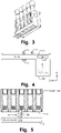
FIG. 3 is a perspective view of a sample rack; -
FIG. 4 is a structural schematic diagram of a feeding channel according to an embodiment; -
FIG. 5 is a schematic structure of a reciprocating feeding mechanism according to an embodiment; -
FIG. 6 is a structural schematic diagram of an automatic sample feeding device according to a further embodiment; -
FIG. 7 is a schematic structure of a buffer region according to an embodiment; -
FIG. 8 is a structural schematic diagram of an automatic sample feeding device according to yet a further embodiment; -
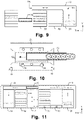
FIG. 9 is a structural schematic diagram for illustrating two channel ports of a feeding channel according to an embodiment; -
FIG. 10 is a schematic structure of a transfer dispatching mechanism according to an embodiment; -
FIG. 11 is a structural schematic diagram of an automatic sample feeding device according to yet still further embodiment; -
FIG. 12 is a structural schematic diagram of a sample analysis system according to an embodiment; -
FIG. 13 is a flow chart of a method for automatic sample feeding control according to an embodiment; -
FIG. 14 is a flow chart of a method for automatic sample feeding control according to another embodiment; -
FIG. 15 is a flow chart of a method for automatic sample feeding control according to a further embodiment; -
FIG. 16 is a flow chart of a method for automatic sample feeding control according to yet a further embodiment. - The disclosure will be further described in detail below through specific implementations in conjunction with the accompanying drawings. Associated similar element reference numerals are used for similar elements in different implementations. In the following implementations, many details are described such that the disclosure may be better understood. However, it may be effortlessly appreciated by persons skilled in the art that some features may be omitted, or may be substituted by other elements, materials, and methods in different cases. In certain cases, some operations involved in the disclosure are not displayed or described in the specification, which is to prevent a core part of the disclosure from being obscured by too much description. Moreover, for persons skilled in the art, detailed description of the involved operations is not necessary, and the involved operations can be thoroughly understood according to the description in the specification and general technical knowledge in the art.
- In addition, the characteristics, operations, or features described in the specification may be combined in any appropriate manner to form various implementations. Meanwhile, the steps or actions in the method description may also be exchanged or adjusted in order in a way that is obvious to persons skilled in the art. Therefore, the various orders in the specification and the accompanying drawings are merely for clear description of a certain embodiment and are not meant to be a necessary order unless it is otherwise stated that a certain order must be followed.
- The serial numbers themselves for the components herein, for example, "first" and "second", are merely used to distinguish described objects, and do not have any sequential or technical meaning. Moreover, as used in the disclosure, "connection" or "coupling", unless otherwise stated, includes both direct and indirect connections (couplings). In addition, up, down, left, and right directions involved herein are defined with respect to the paper direction of the attached drawings.
- Referring to
FIGS. 1 and 2 , an automatic sample feeding device disclosed in some embodiments of the disclosure includes afeeding channel 10, aloading region 20, abuffer region 30, anemergency region 40, and atransfer dispatching mechanism 50. It should be noted that the automatic sample feeding device in some embodiments may not include theemergency region 40, such as the example ofFIG. 1 , and the automatic sample feeding device in some embodiments may include theemergency region 40, such as the example ofFIG. 2 . The components of the automatic sample feeding device are described in detail below. - The
feeding channel 10 is a place for sample aspiration of an analyzer. In some embodiments, the feedingchannel 10 is provided in a first direction, such as in an X-axis direction inFIGS. 1 and 2 . The feedingchannel 10 is configured to support a sample rack and to allow the sample rack to move along a lengthwise direction thereof in the feeding channel. As shown inFIG. 3 , it is an example of the sample rack, a length, a width and a height of the sample rack are respectively represented by L, W and H, the lengthwise direction of the sample rack is a measuring direction, in which the length L is measured, and a height direction is a measuring direction, in which the height H is measured. In some embodiments, the feedingchannel 10 is further provided with a sample aspiration position, such as asample aspiration position 10a inFIGS. 1 and 2 , which is configured such that, when a sample on the sample rack is located at the sample aspiration position of the feedingchannel 10, the sample on the sample rack is aspirated. In other words, when the sample on the sample rack is located at the sample aspiration position of the feedingchannel 10, the analyzer aspirates the sample, and the sample rack may be constantly moved in the first direction such that samples carried by the sample rack pass through the sample aspiration position one by one, allowing the analyzer to aspirate all the samples on the sample rack respectively. - Referring to
FIG. 4 , in order to allow the sample rack to reciprocate in the feedingchannel 10, namely, to move in a direction (such as a forward X-axis direction in the figure) same as the first direction and in a direction (such as a reverse X-axis direction in the figure) opposite to the first direction, or to move in leftward and rightward directions in the figure, areciprocating feeding mechanism 11 may be provided on the feedingchannel 10. By providing thereciprocating feeding mechanism 11 on the feedingchannel 10, the sample rack is bidirectionally conveyed on one track, such that sample aspiration of initial test samples, retest samples and emergency samples may be completed by using one feeding channel, and meanwhile priority processing of the retest samples and the emergency samples may be achieved, overcoming the defect that the retest samples and the emergency samples need to wait in line in the prior art. In a specific embodiment, referring toFIG. 5 , thereciprocating feeding mechanism 11 includes anelectric motor 11a and acatch portion 11b. The bottom of the sample rack is provided with a plurality ofgrooves 11c. Thecatch portion 11b is capable of being driven by theelectric motor 11a to extend and retract in the height direction of the sample rack, and to move in directions same as and opposite to the first direction; when being driven to extend out, thecatch portion 11b is capable of cooperating with any one of the grooves of the sample rack, such that when thecatch portion 11b is driven, the sample rack is driven to move together in the directions same as and opposite to the first direction. For example, when thecatch portion 11b is driven to move in the first direction, the sample rack may be driven to move together in the first direction, and when thecatch portion 11b is driven to move in the direction opposite to the first direction, the sample rack may be driven to move together in the direction opposite to the first direction. - Other components may also be provided on the feeding
channel 10, such as at least one of a test tube/test tube cap presence/absence detection mechanism 12, a test tube rotation mechanism 13 and ascanner 14. Thescanner 14 is configured to scan a label of a test tube for acquiring sample information. The test tube rotation mechanism 13 is a test tube rotation mechanism configured to drive the test tube to rotate, for example, when the sample rack moves in the feedingchannel 10, if thescanner 14 cannot scan the test tube carried on the sample rack-possibly because a label side of the test tube does not face thescanner 14, the test tube rotation mechanism 13 drives the test tube to rotate at this time such that the label of the test tube is aligned with thescanner 14. The test tube/test tube cap presence/absence detection mechanism 12 is a test tube/test tube cap presence/absence detection mechanism configured to detect the presence/absence of a test tube and the presence/absence of a test tube cap on the test tube, and if it is detected that there is no test tube at a sample position on the sample rack, the automatic sample feeding device may output an alarm. - The above are some illustrations about the feeding
channel 10. - The
loading region 20 is in communication with the feedingchannel 10 and is configured to support the sample rack with its lengthwise direction along the first direction and to allow the sample rack to move towards the feedingchannel 10 in a second direction and then to move to the sample aspiration position in the first direction. In some embodiments herein, the first direction and the second direction are perpendicular to each other, for example, the X-axis direction in the figures is the first direction, and the Y-axis direction is the second direction. Theloading region 20 may be configured for a user to place sample racks carrying samples to be tested in batches. - The
buffer region 30 is configured to support a sample rack, which waits for a test result after sample aspiration, and/or support a sample rack storing emergency samples. In some embodiments, thebuffer region 30 supports a sample rack with its lengthwise direction parallel to the first direction, allows the sample rack to move out of thebuffer region 30 in a direction same as or opposite to the first direction, and allows the sample rack to move into thebuffer region 30 in a direction opposite to or same as the first direction. In a specific embodiment, referring toFIG. 6 , thebuffer region 30 includes a plurality ofbuffer positions 31 sequentially provided in the second direction; and any one of the buffer positions 31 is capable of supporting a sample rack with its lengthwise direction parallel to the first direction, allows the sample rack to move out of thebuffer region 30 in the direction same as or opposite to the first direction, and allows the sample rack to move into thebuffer region 30 in the direction opposite to or same as the first direction. In the examples ofFIGS. 1 and 2 , the sample rack moves out of thebuffer region 30 in the first direction and moves into the buffer region in the direction opposite to the first direction. - In order to enable each sample rack to be stably placed in the buffer region, in some embodiments, referring to
FIG. 7 , thebuffer region 30 includes abaffle plate 31a and a plurality ofpartition plates 31b, the arrangement direction of the plurality ofpartition plates 31b is parallel to the first direction, the plurality ofpartition plates 31b are provided at intervals and are arranged in the second direction, and abuffer position 31 is formed between twoadjacent partition plates 31b; and thebaffle plate 31a is provided in a direction parallel to the second direction, and thebaffle plate 31a is connected to one end of each of the plurality ofpartition plates 31b. - In the case where the total number of the buffer positions in the
buffer region 30 is substantially constant, in some embodiments, onebuffer region 30 may be provided, as is the case of the examples inFIGS. 1 and 2 . In some embodiments, at least two, for example two or more,buffer regions 30 are provided, and all the buffer positions are allocated to two ormore buffer regions 30 to change a design size in a certain dimension. In some embodiments, when there aremultiple buffer regions 30, these buffer regions are provided in parallel. In some embodiments, when there aremultiple buffer regions 30, these buffer regions are provided in parallel in the first direction. For example,FIG. 8 shows an example that the buffer regions are provided in parallel in the first direction, and it can be seen that although the length of the automatic sample feeding device in the first direction is increased, the automatic sample feeding device can be subsequently provided on one side of the analyzer, and the first direction is consistent with a lengthwise direction of the analyzer; therefore, in practical situations, there is a sufficient design space for the length of the automatic analyzer in the first direction; furthermore, by providing the buffer regions in parallel in the first direction, the length in the second direction may be decreased, while the design space in the second direction is relatively small, and in practical situations, it is desirable to decrease the length of the automatic analyzer in the second direction as much as possible. With such an arrangement, when the automatic sample feeding is assembled with the analyzer, as described above, the automatic sample feeding device is provided on one side of the analyzer, and the first direction is consistent with the lengthwise direction of the analyzer, so that the lengthwise direction (namely, the length in the first direction) of the final complete machine may be kept constant, and the longitudinal depth (namely, the length in the second direction) is not increased much due to addition of the automatic sample feeding device. In addition, with regard to thebuffer region 30 on the left inFIG. 8 , the sample rack is capable of moving into thebuffer region 30 in the first direction and moving out of the buffer region in the direction opposite to the first direction; and with regard to thebuffer region 30 on the right inFIG. 8 , the sample rack is capable of moving out of the buffer region in the first direction and moving into the buffer region in the direction opposite to the first direction. - Taking an example that two
buffer regions 30 are provided, in some embodiments, the twobuffer regions 30 are provided apart by anintermediate region 32, and the twobuffer regions 30 are symmetrically provided with theintermediate region 32 as an axis of symmetry. A length of theintermediate region 32 in the first direction is at least a length of the sample rack such that the sample rack in each of the twobuffer regions 30 is capable of completely moving into theintermediate region 32 in a direction same as or opposite to the first direction. and then moving in a direction same as or opposite to the second direction. Also takingFIG. 8 as an example, with regard to thebuffer region 30 on the left inFIG. 8 , the sample rack is capable of moving out of the buffer region in the direction opposite to the first direction, and entering the intermediate region, and is capable of moving into the buffer region from the intermediate region in the direction same as the first direction; and with regard to thebuffer region 30 on the right inFIG. 8 , the sample rack is capable of moving out of the buffer region in the first direction and entering the intermediate region, and is capable of moving into the buffer region from the intermediate region in the direction opposite to the first direction. Thetransfer dispatching mechanism 50 moves back and forth in theintermediate region 32. Thetransfer dispatching mechanism 50 moves in the direction opposite to the second direction so as to dispatch the sample rack moving out of the feedingchannel 10 to acorresponding buffer position 31 of thebuffer region 30; and thetransfer dispatching mechanism 50 moves in the direction same as the second direction to take out and dispatch samples in thecorresponding buffer position 31 of thebuffer region 30 to the feedingchannel 10 for sample re-aspiration. - In some embodiments, the
loading region 20 and thebuffer region 30 are provided on a same side of the feedingchannel 10, for example, provided below the feedingchannel 10 in the figures. - The above are some illustrations about the
buffer region 30. - The
emergency region 40 is configured for a user to place a sample rack, for example, the user may place a sample rack carrying emergency samples onto theemergency region 40. In some embodiments, theemergency region 40 is at least connected to thebuffer region 30, and when there is a plurality ofbuffer regions 30, theemergency region 40 is in communication with at least one of thebuffer regions 30. Theemergency region 40 is configured to allow the sample rack to move from theemergency region 40 into thebuffer region 30 in communication with theemergency region 40. In some embodiments, theemergency region 40 supports the sample rack placed with its lengthwise direction along the first direction and allows the sample rack to move from theemergency region 40 to thebuffer region 30 in communication therewith in the direction same as or opposite to the first direction. In some embodiments, theemergency region 40 includes at least oneemergency position 41; and the at least oneemergency position 41 is aligned with abuffer position 31 of thebuffer region 30 and configured to support the sample rack placed with its lengthwise direction along the first direction and to allow the sample rack to move out of the emergency positions 41 in the direction same as or opposite to the first direction and enter thebuffer position 31 aligned with theemergency position 41. As two examples inFIGS. 6 and 8 , the sample rack in theemergency region 40 may move from theemergency region 40 to thebuffer region 30 in communication therewith in the first direction, for example, move from theemergency position 41 to thebuffer position 31 aligned with theemergency position 41 in the first direction. As described above, in some embodiments, thebuffer region 30 includes abaffle plate 31a andpartition plates 31b, it may be appreciated that when the automatic sample feeding device has theemergency region 40, thepartition plates 31b do not separate theemergency region 40 from thebuffer region 30, namely, thepartition plates 31b do not prevent the sample rack from entering thebuffer region 30 in communication with theemergency region 40 from the emergency region. For example, nopartition plate 31b is provided at thebuffer position 31 in communication with theemergency position 41. - In some embodiments, the
emergency region 40 may also be provided in thebuffer region 30. In some embodiments, thebuffer position 31 of at least onebuffer region 30 is provided as the emergency position for the user to place a sample rack. - In some embodiments, the
emergency region 40 is provided with a button (not shown in the figures) that is triggered to generate an instruction of testing the sample rack in theemergency region 40, namely, an emergency instruction. - The above are some illustrations about the
emergency region 40. - The
transfer dispatching mechanism 50 is configured to dispatch the sample rack between thebuffer region 30 and the feedingchannel 10. In some embodiments, thetransfer dispatching mechanism 50 moves the sample rack after sample aspiration out of the feedingchannel 10 and then moves the sample rack into thebuffer region 30 to wait for the test result, and when the test result of the sample indicates that the sample needs to be retested, the transfer dispatching mechanism moves the corresponding sample rack in thebuffer region 30 out of thebuffer region 30 and moves the sample rack into the feedingchannel 10. In some embodiments, when an emergency instruction inputted by a user is received, the sample rack corresponding to the emergency instruction in thebuffer region 30 moves out of thebuffer region 30 and moves into the feedingchannel 10. - In some embodiments, the sample aspiration position of the feeding
channel 10 is located between theloading region 20 and thebuffer region 30; and the sample rack, which moves from theloading region 20 to the feedingchannel 10, moves to the sample aspiration position in the first direction, while the sample rack, which is taken out from thebuffer region 30 and moved into the feedingchannel 10 by thetransfer dispatching mechanism 50, moves to the sample aspiration position in a direction opposite to the first direction, for example, thereciprocating feeding mechanism 11 of the feedingchannel 10 drives the sample rack, which moves from theloading region 20 to the feedingchannel 10, to move to the sample aspiration position in the first direction, and drives the sample rack, which is taken out from thebuffer region 30 and moved into the feedingchannel 10 by thetransfer dispatching mechanism 50, to move to the sample aspiration position in the direction opposite to the first direction. In some specific embodiments, referring toFIG. 9 , the feedingchannel 10 includes afirst channel port 10b and asecond channel port 10c, theloading region 20 is located at one end of thefirst channel port 10b of the feeding channel, and thebuffer region 30 is located at one end of thesecond channel port 10c of the feedingchannel 10, such that theloading region 20 moves the sample rack from thefirst channel port 10b to the feedingchannel 10, and such that thetransfer dispatching mechanism 50 moves the sample rack from thebuffer region 30 to the feedingchannel 10 via thesecond channel port 10c. In some specific embodiments, thetransfer dispatching mechanism 50 is configured to move the sample rack at least in the second direction such that the sample rack can move to the feedingchannel 10 after moving out of thebuffer region 30, and to move the sample rack at least in a direction opposite to the second direction such that the sample rack can move into thebuffer region 30 after moving out of the feedingchannel 10. It can be seen that by redesigning the arrangement, functions of the feedingchannel 10, theloading region 20 and thebuffer region 30 and sample rack access paths, the disclosure allows normal samples to be tested to enter the feedingchannel 10 from theloading region 20 and to move to the sample aspiration position in the first direction to complete sample aspiration; but samples requiring retest and emergency treatment may enter the feedingchannel 10 from thebuffer region 30 and move to the sample aspiration position in a direction opposite to the first direction for sample aspiration, so that the samples requiring retest and emergency treatment pass through a completely different path accessing the sample aspiration position from the normal samples to be tested, allowing the samples requiring retest and emergency treatment to be preferentially treated, without waiting for other normal samples to be tested on the path accessing the sample aspiration position thereof, and without queuing with the normal samples to be tested and jumping a queue. - There are various implementation structures of the
transfer dispatching mechanism 50. For example, in some embodiments, referring toFIG. 10 , thetransfer dispatching mechanism 50 includes anelectric motor 51 and a testtube rack bracket 52; the testtube rack bracket 52 is configured to carry the sample rack with its lengthwise direction along the first direction; and theelectric motor 51 is capable of driving the testtube rack bracket 52 to move in directions same as and opposite to the second direction so as to drive the sample rack carried by the testtube rack bracket 52 to move together in the directions same as and opposite to the second direction. In some embodiments, thetransfer dispatching mechanism 50 further includes a test tuberack transferring mechanism 53, wherein the test tuberack transferring mechanism 53 is configured to move the sample rack with its lengthwise direction along the first direction into or out of the testtube rack bracket 52 in a direction same as or opposite to the first direction. In some embodiments, thetransfer dispatching mechanism 50 further includes a first test tube rack presence/absence detection mechanism 54 and/or a second test tube rack presence/absence detection mechanism 55. The first test tube rack presence/absence detection mechanism 54 is configured to detect whether the testtube rack bracket 52 carries a sample rack. The second test tube rack presence/absence detection mechanism 55 is configured to detect whether the buffer position aligned with the testtube rack bracket 52 carries a sample rack. - The above are some illustrations about the
transfer dispatching mechanism 50. - Referring to
FIG. 11 , the automatic sample feeding device of some embodiments of the disclosure further includes an unloadingchannel 60 and an unloadingregion 70. - The unloading
channel 60 is provided in the first direction and configured to support the sample rack with its lengthwise direction along the first direction and to allow the sample rack to move from the unloadingchannel 60 to the unloadingregion 70 in a direction opposite to the second direction. In some embodiments, the unloadingchannel 60 is aligned with the feedingchannel 10. Specifically, in some embodiments, thetransfer dispatching mechanism 50 is configured to move the sample rack within thebuffer region 30, which has a test result indicating that no sample needs to be retested, at least in the second direction, such that the sample rack can move out of thebuffer region 30 and then move into the unloadingchannel 60. - The unloading
region 70 is configured to support the sample rack with its lengthwise direction along the first direction and to allow the sample rack to move in a direction opposite to the second direction. In some examples, the user may take out the sample rack that completes testing or is to be recycled from the unloadingregion 70. - It can be seen that the sample rack carrying samples to be tested enters the feeding
channel 10 from theloading region 20 and does not need to be dispatched by means of thetransfer dispatching mechanism 50; but, thetransfer dispatching mechanism 50 is mainly responsible for dispatching the sample rack carrying retest samples and the sample rack carrying emergency samples in thebuffer region 30 to the feedingchannel 10, and dispatching the sample rack that completes testing or is to be recycled to the unloadingchannel 60; and in terms of function, the dispatching for sample aspiration of samples to be tested entering the system for the first time is distinguished from the dispatching for special functions, namely, the dispatching for emergency treatment, the dispatching for retest and the dispatching for unloading. The dispatching for sample aspiration is realized by means of relevant mechanisms on theloading region 20 and the feedingchannel 10, the dispatching for emergency treatment, the dispatching for retest and the dispatching for unloading are realized by thetransfer dispatching mechanism 50, thereby obtaining a clear division of work, and obtaining a high efficiency of coordinating, handling and achieving the dispatching process in the whole test process. - In some embodiments, the unloading
region 70, thebuffer region 30 and theloading region 20 are all located on a same side of the feedingchannel 10, for example, below the feedingchannel 10 in the figures. In some embodiments, theloading region 20, thebuffer region 30, and the unloadingregion 70 are sequentially provided in the first direction. - The above is description of the automatic sample feeding device of some embodiments of the disclosure.
- The automatic sample feeding device is configured to supply the analyzer with a sample rack carrying a sample. Referring to
FIG. 12 , in some embodiments of the disclosure, disclosed is a sample analysis system, including an automaticsample feeding device 1 andanalyzer 2, wherein the automaticsample feeding device 1 may be the automatic sample feeding device as disclosed in any one of the embodiments herein, and theanalyzer 2 is configured to aspirate a sample from the sample rack supplied by the automaticsample feeding device 1 and to perform analysis. The automaticsample feeding device 1 is provided on one side of theanalyzer 2, and the first direction is consistent with the lengthwise direction of theanalyzer 2. With such an arrangement, the lengthwise direction (namely, the length in the first direction) of the final complete machine may be kept unchanged, and the longitudinal depth (namely, the length in the second direction) will not increase much due to addition of the automatic sample feeding device, so that it is very advantageous to arrange the final complete machine in a room, and the space of the department is effectively used. Specifically, theloading region 20 and thebuffer region 30 are located on a first side of the feedingchannel 10, for example, located in the lower part in the figure. When the automaticsample feeding device 1 further includes an unloadingregion 70, theloading region 20, thebuffer region 30 and the unloadingregion 70 are located on the first side of the feedingchannel 10, for example, located in the lower part in the figure; and theanalyzer 2 is located on a second side of the automaticsample feeding device 1 opposite to the first side, for example, located in the upper part in the figure. - The flow of the automatic sample feeding device supplying the sample rack to the analyzer will be described below.
- The description is made by taking
FIG. 8 ,FIG. 11 orFIG. 12 as examples, wherein the first direction is a forward X-axis direction, the direction opposite to the first direction is a reverse X-axis direction, the second direction is a forward Y-axis direction, and the direction opposite to the second direction is a reverse Y-axis direction. - A sample rack carrying samples to be tested in the
loading region 20 is moved in the second direction to enter the feedingchannel 10, and then moved in the feedingchannel 10 in the first direction to pass through the sample aspiration position, the analyzer performs sample aspiration on the sample located at the sample aspiration position, and after all the samples on the sample rack are aspirated, the sample rack continues to move in the first direction to enter thetransfer dispatching mechanism 50 from the feedingchannel 10, and after receiving the sample rack, the transfer dispatching mechanism drives the sample rack to move in the direction opposite to the second direction and then stops after aligning with anempty buffer position 31. If theempty buffer position 31 is within theleft buffer region 30 in the figure, the sample rack is moved in the first direction to enter theleft buffer region 30, and if theempty buffer position 31 is within theright buffer region 30 in the figure, the sample rack is moved in the direction opposite to the first direction to enter theright buffer region 30. The purpose of the sample rack entering thebuffer region 30 is to wait for test results of the samples carried thereby. - When the test result of a sample indicates that the sample needs to be retested, the corresponding sample rack in the buffer region 30 is moved out of the buffer region 30 and moved into the feeding channel 10, and specifically, the transfer dispatching mechanism 50 moves and aligns with the buffer position 31 where the sample rack is located; if the sample rack is located in the left buffer region 30 in the figure, the sample rack is moved in the direction opposite to the first direction to enter the transfer dispatching mechanism 50; if the sample rack is located in the right buffer region 30 in the figure, the sample rack is moved in the first direction to enter the transfer dispatching mechanism 50; after receiving the sample rack, the transfer dispatching mechanism 50 moves in the second direction to align with the feeding channel 10, then moves the sample rack in the direction opposite to the first direction to enter the feeding channel 10 such that the sample to be retested passes through the sample aspiration position, and the analyzer aspirates the sample to be retested; after all samples to be retested on the sample rack are aspirated, the sample rack is moved in the first direction to enter the transfer dispatching mechanism 50 from the feeding channel 10, and the transfer dispatching mechanism 50 then moves in the direction opposite to the second direction to re-dispatch the sample rack back to the buffer region 30. In some test modes, a sample only needs to be retested once, namely, after being aspirated for the first time, the sample waits for a test result in the buffer region; if the test result indicates that a retest is needed, the sample is retested, and then the sample does not need to wait for a test result of retesting again, but is directly dispatched, for example, to the unloading region; in this mode, after all samples to be retested on the sample rack are aspirated, the sample rack is moved in the first direction to enter the
transfer dispatching mechanism 50 from the feedingchannel 10, then continues to enter the unloadingchannel 60 from thetransfer dispatching mechanism 50 in the first direction, and eventually enters the unloadingregion 70 through the unloadingchannel 60 in the direction opposite to the second direction. During this process, it is possible to require the sample rack to move a distance along the unloadingchannel 60 in the first direction and then enter the unloadingregion 70 in the direction opposite to the second direction. - When the test results of all the samples on the sample rack in the
buffer region 30 indicate that the corresponding samples do not need to be retested, the corresponding sample rack in thebuffer region 30 is moved out from thebuffer region 30 and is finally moved into the unloadingregion 70. Thetransfer dispatching mechanism 50 moves and aligns with thebuffer position 31 where the sample rack is located; if the sample rack is located in theleft buffer region 30 in the figure, the sample rack is moved in the direction opposite to the first direction to enter thetransfer dispatching mechanism 50; if the sample rack is located in theright buffer region 30 in the figure, the sample rack is moved in the first direction to enter thetransfer dispatching mechanism 50; and after receiving the sample rack, thetransfer dispatching mechanism 50 moves in the second direction to align with the unloadingchannel 60, and the sample rack is moved from thetransfer dispatching mechanism 50 to the unloadingchannel 60 in the first direction, and finally enters the unloadingregion 70 in the direction opposite to the second direction through the unloadingchannel 60. During this process, it is possible to require the sample rack to move a distance in the first direction along the unloadingchannel 60 and then enter the unloadingregion 70 in the direction opposite to the second direction. - The dispatching and testing process of a sample rack carrying emergency samples is also similar, and after a user places the sample rack in the
emergency region 40, the sample rack is moved from theemergency region 40 in the first direction to enter thebuffer region 30 in communication therewith; of course, for embodiments in which theemergency region 40 is provided within thebuffer region 30, for example, onebuffer position 31 in thebuffer region 30 is provided as theemergency position 41, the sample rack carrying the emergency samples itself is already in thebuffer region 30. The sample rack is then moved out from thebuffer region 30 and moved into the feedingchannel 10, and specifically, thetransfer dispatching mechanism 50 moves and aligns with thebuffer position 31 where the sample rack is located. It is shown in the figure that the sample rack is located in theright buffer region 30 in the figure, and therefore the sample rack is moved in the first direction to enter thetransfer dispatching mechanism 50; and after receiving the sample rack, thetransfer dispatching mechanism 50 moves in the second direction to align with the feedingchannel 10, and then the sample rack is moved in the direction opposite to the first direction to enter the feedingchannel 10, such that the samples pass through the sample aspiration position one by one, and the analyzer aspirates each sample of the sample rack; and after each sample of the sample rack is aspirated, the sample rack is moved in the first direction to enter thetransfer dispatching mechanism 50 from the feedingchannel 10, and thetransfer dispatching mechanism 50 then moves in the direction opposite to the second direction to re-dispatch the sample rack back to thebuffer region 30. The purpose of the sample rack entering thebuffer region 30 at the moment is to wait for test results of the samples carried thereby. When the test result of a sample on the sample rack carrying the emergency samples indicates that the sample needs to be retested, the sample rack needs to enter the feedingchannel 10 again for retesting of the corresponding sample, and the specific dispatching process may refer to in the above description, which will not be repeatedly described herein; and similarly, when the test results for all the samples on the sample rack carrying emergency samples indicate that no corresponding sample needs to be retested, the sample rack is moved out from thebuffer region 30 and is eventually moved into the unloadingregion 70, and the specific dispatching process may refer to in the above description, which will not be repeatedly described herein. - In some embodiments of the disclosure, further disclosed is a method for automatic sample feeding control that may be applied to the automatic sample feeding device disclosed in any one of the embodiments herein.
- Referring to
FIG. 13 , the method for automatic sample feeding control in some embodiments includes the following steps: - Step 100 (namely, sample rack placement step), controlling a sample rack to move from the
loading region 20 to the feedingchannel 10 in the second direction; - Step 120 (namely, sample rack feeding step), controlling the sample rack to move in the first direction along the feeding
channel 10 to the sample aspiration position located on the feedingchannel 10 for sample aspiration; - Step 140 (namely, sample rack buffer step), controlling the
transfer dispatching mechanism 50 to move the sample rack, which moves out of the feedingchannel 10 after sample aspiration, to thebuffer region 30 in the direction opposite to the second direction, and driving the sample rack to move into thebuffer region 30 in the direction same as or opposite to the first direction so as to wait for a test result. - Taking
FIG. 8 ,FIG. 11 orFIG. 12 as an example for illustration, after all the samples on the sample rack are aspirated, the sample rack continues to move in the first direction to enter thetransfer dispatching mechanism 50 from the feedingchannel 10, and after receiving the sample rack, the transfer dispatching mechanism drives the sample rack to move in the direction opposite to the second direction and then stops after aligning with anempty buffer position 31. If theempty buffer position 31 is within theleft buffer region 30 in the figure, the sample rack is moved in the first direction to enter theleft buffer region 30, and if theempty buffer position 31 is in theright buffer region 30 in the figure, the sample rack is moved in the direction opposite to the first direction to enter theright buffer region 30. The purpose of the sample rack entering thebuffer region 30 is to wait for test results of the samples carried thereby. -
Step 150, namely, retest step, when the test result of a sample indicates that the sample needs to be retested, controlling the transfer dispatching mechanism to take out the sample rack corresponding to a retest instruction in the buffer region in the direction opposite to or same as the first direction and then dispatch the sample rack to the feeding channel in the second direction, so as to move to the sample aspiration position in the direction opposite to the first direction along the feeding channel for sample aspiration. It should be noted that the retest instruction may be automatically generated by the sample analysis system, or the analyzer, or the automatic sample feeding device when it is determined that there is a sample that needs to be retested, or may be issued by a user by means of a mouse or a keyboard, etc., for example, after the user sees the test results on a display interface, a sample on a certain sample rack is manually designated for retesting. - Taking
FIG. 8 ,FIG. 11 orFIG. 12 as an example for illustration, when the test result of a sample indicates that the sample needs to be retested, the corresponding sample rack in thebuffer region 30 is moved out of thebuffer region 30 and moved into the feedingchannel 10, and specifically, thetransfer dispatching mechanism 50 moves and aligns with thebuffer position 31 where the sample rack is located; if the sample rack is located in theleft buffer region 30 in the figure, the sample rack is moved in the direction opposite to the first direction to enter thetransfer dispatching mechanism 50; if the sample rack is located in theright buffer region 30 in the figure, the sample rack is moved in the first direction to enter thetransfer dispatching mechanism 50; and after receiving the sample rack, thetransfer dispatching mechanism 50 moves in the second direction to align with the feedingchannel 10, and the sample rack is then moved in the direction opposite to the first direction to enter the feedingchannel 10 such that the sample to be retested passes through the sample aspiration position, and the analyzer aspirates the sample to be retested. After all samples to be retested on the sample rack are aspirated, the sample rack is moved in the first direction to enter thetransfer dispatching mechanism 50 from the feedingchannel 10, and thetransfer dispatching mechanism 50 then moves in the direction opposite to the second direction, so as to re-dispatched the sample rack back to thebuffer region 30. In some test modes, a sample only need to be retested once, namely, after being aspirated for the first time, the sample waits for the test result in the buffer region; if the test result indicates that a retest is needed, the sample is retested, and then the sample does not need to wait for a test result of retesting again, but is directly dispatched, for example, to the unloading region; and in this mode, after all samples to be retested on the sample rack are aspirated, the sample rack is moved in the first direction to enter thetransfer dispatching mechanism 50 from the feedingchannel 10, then continues to enter the unloadingchannel 60 from thetransfer dispatching mechanism 50 in the first direction, and eventually enters the unloadingregion 70 through the unloadingchannel 60 in the direction opposite to the second direction. During this process, it is possible to require to move the sample rack a distance along the unloadingchannel 60 in the first direction and then enter the unloadingregion 70 in the direction opposite to the second direction. - In some cases, when the sample rack needs to enter the feeding
channel 10 from thebuffer region 30 for retesting, it is possible that there is already a sample rack on the feedingchannel 10, and some avoidance strategies need to be taken to deal with this relatively complex situation. - In some embodiments, the
retest step 150 may include: when the test result of the sample indicates that the sample needs to be retested, controlling a sample rack located at the sample aspiration position to move out along the feeding channel, which means that there is already a sample rack in the feedingchannel 10 at this time, and the sample on the sample rack is rightly located at the sample aspiration position, so that the samples on the sample rack being fed can be all aspirated, and then controlling thetransfer dispatching mechanism 50 to dispatch the sample rack to thebuffer region 30 to wait for test results; and then, controlling thetransfer dispatching mechanism 50 to take out the sample rack corresponding to the retest instruction in the buffer region in the direction same as or opposite to the first direction and then dispatch the sample rack to the feeding channel in the direction opposite to the second direction so as to move to the sample aspiration position along the feeding channel in the direction opposite to the first direction for sample aspiration. - In some embodiments, the
retest step 150 may include: when the test result of the sample indicates that the sample needs to be retested, controlling a sample rack located at the sample aspiration position to move out along the feeding channel in the direction opposite to the first direction, which means that there is already a sample rack in the feedingchannel 10 at this time, and the sample on the sample rack is rightly located at the sample aspiration position, so that the sample rack can be moved in the direction opposite to the first direction to make room for the sample aspiration position; then controlling thetransfer dispatching mechanism 50 to take out the sample rack corresponding to the retest instruction in the buffer region in the direction same as or opposite to the first direction and then dispatch the sample rack to the feeding channel in the direction opposite to the second direction so as to move to the sample aspiration position along the feeding channel in the direction opposite to the first direction for sample aspiration. - It can be seen that the avoidance strategies are achieved by controlling the sample rack in the feeding channel to move for avoidance. Thus, in some embodiments, the
retest step 150 may include: when it is determined that there is a sample rack in the feeding channel, controlling the sample rack in the feeding channel to move for avoidance. - In some specific embodiments, it may be handled according to whether currently one or more sample racks is in the feeding
channel 10. In some embodiments, controlling the sample rack in the feeding channel to move for avoidance includes: when it is determined that there is only one sample rack in the feedingchannel 10, controlling the sample rack to move in the feeding channel for avoidance, for example, firstly controlling the sample rack to move to the sample aspiration position such that each sample on the sample rack is aspirated, and then controlling the sample rack to move in the feeding channel for avoidance, for example, controlling thetransfer dispatching mechanism 50 to dispatch the sample rack after sample aspiration to thebuffer region 30 to wait for test results, or controlling the sample rack to move in the direction opposite to the first direction to make room for the sample aspiration position. In some embodiments, controlling the sample rack in the feeding channel to move for avoidance includes: when it is determined that there are a plurality of sample racks in the feedingchannel 10, controlling the sample rack closest to the sample aspiration position to move to the sample aspiration position such that each sample on the sample rack is aspirated, then controlling the sample rack after sample aspiration to move out of the feeding channel, for example, controlling thetransfer dispatching mechanism 50 to dispatch the sample rack after sample aspiration to thebuffer region 30 to wait for test results, and controlling other sample racks in the feeding channel to move in the feeding channel for avoidance, for example, controlling these other sample racks to move in the feedingchannel 10 in the direction opposite to the first direction so as to make room for the sample aspiration position, or even controlling the sample racks to reenter theloading region 20. - In some specific embodiments, it may also be handled according to whether or not the feeding
channel 10 is fully loaded. In some embodiments, controlling the sample rack in the feeding channel to move for avoidance includes: when it is determined that the feedingchannel 10 is not fully loaded, controlling each sample rack to move in the feedingchannel 10 for avoidance, for example, controlling each sample rack to move in the feedingchannel 10 in the direction opposite to the first direction to make room for the sample aspiration position, or even controlling each sample rack to reenter theloading region 20. In some embodiments, controlling the sample rack in the feeding channel to move for avoidance includes: when it is determined that the feeding channel is fully loaded, controlling the sample rack closest to the sample aspiration position to move to the sample aspiration position such that each sample on the sample rack is aspirated, then controlling the sample rack after sample aspiration to move out of the feeding channel, for example, controlling thetransfer dispatching mechanism 50 to dispatch the sample rack after sample aspiration to thebuffer region 30 to wait for test results, and controlling other sample racks in the feeding channel to move on the feeding channel for avoidance, for example, controlling these other sample racks to move in the feedingchannel 10 in the direction opposite to the first direction so as to make room for the sample aspiration position, or even controlling the sample racks to reenter theloading region 20. - With the above avoidance strategies and specific methods, it is possible to preferentially process the samples that need to be retested, so that the time required for obtaining final sample test results meets the requirement of the department.
- Referring to
FIG. 14 , the method for automatic sample feeding control in some embodiments includes the following steps: - Step 100 (namely, sample rack placement step), controlling a sample rack to move from the
loading region 20 to the feedingchannel 10 in the second direction; - Step 120 (namely, sample rack feeding step), controlling the sample rack to move in the first direction along the feeding
channel 10 to the sample aspiration position located on the feedingchannel 10 for sample aspiration; - Step 140 (namely, sample rack buffer step), controlling the
transfer dispatching mechanism 50 to move the sample rack, which is moved out of the feedingchannel 10 after sample aspiration, to thebuffer region 30 in the direction opposite to the second direction, and driving the sample rack to move into thebuffer region 30 in the direction same as or opposite to the first direction; - Step 160 (namely, emergency step), controlling, in response to an emergency instruction inputted by the user, the transfer dispatching mechanism to move the sample rack out of the
buffer region 30 in the direction same as or opposite to the first direction from thebuffer region 30 and move the sample rack to the feedingchannel 10 in the second direction, such that the sample rack is moved to the sample aspiration position along the feedingchannel 10 in the direction opposite to the first direction. - In some examples, the
emergency region 40 is a region in communication with thebuffer region 30, then theemergency step 160 further includes: controlling, in response to an emergency instruction inputted by the user, the sample rack located within theemergency region 40 to move from theemergency region 40 to thebuffer region 30 in communication with the emergency region in the direction same as or opposite to the first direction. Specifically,step 160 includes a first emergency step: controlling, in response to an emergency instruction inputted by a user, the sample rack located in theemergency region 40 to move from theemergency region 40 to thebuffer region 30 in communication with the emergency region in the direction same as or opposite to the first direction; controlling the sample rack to move out of thebuffer region 30 in the direction same as or opposite to the first direction from thebuffer region 30; controlling the sample rack moved out of thebuffer region 30 to move in the second direction; and controlling the sample rack to move into the feedingchannel 10 and to move to the sample aspiration position along the feedingchannel 10 in the direction opposite to the first direction for sample aspiration. - In some examples, if the
emergency region 40 is provided in thebuffer region 30, or abuffer position 31 is provided as theemergency position 41, theemergency step 160 includes: directly controlling, in response to an emergency instruction inputted by the user, the sample rack at theemergency position 41 in thebuffer region 30 to move out of thebuffer region 30 in the direction same as or opposite to the first direction from thebuffer region 30 and to move to the feedingchannel 10 in the second direction. Specifically,step 160 includes a second emergency step: controlling, in response to an emergency instruction input by the user, the sample rack at theemergency position 41 in thebuffer region 40 to move out of thebuffer region 30 in the direction same as or opposite to the first direction; controlling the sample rack moved out of thebuffer region 30 to move in the second direction; and controlling the sample rack to move into the feedingchannel 10 and to move to the sample aspiration position along the feeding channel in the direction opposite to the first direction for sample aspiration. - In some cases, when a sample rack carrying emergency samples needs to enter the feeding
channel 10 from thebuffer region 30 for testing, it is possible that there is already a sample rack in the feedingchannel 10, and some avoidance strategies need to be taken to deal with this relatively complex situation. - In some embodiments, the
emergency step 160 further includes: when it is determined that there is a sample rack in the feedingchannel 10, controlling the sample rack in the feeding channel to move for avoidance. - In some specific embodiments, it may be handled according to whether currently one or more sample racks is in the feeding
channel 10. In some embodiments, controlling the sample rack in the feeding channel to move for avoidance includes: when it is determined that there is only one sample rack in the feedingchannel 10, controlling the sample rack to move in the feeding channel for avoidance, for example, firstly controlling the sample rack to move to the sample aspiration position such that each sample on the sample rack is aspirated, and then controlling the sample rack to move in the feeding channel for avoidance, for example, controlling thetransfer dispatching mechanism 50 to dispatch the sample rack after sample aspiration to thebuffer region 30 to wait for test results, or controlling the sample rack to move in the direction opposite to the first direction to make room for the sample aspiration position. In some embodiments, controlling the sample rack on the feeding channel to move for avoidance includes: when it is determined that there are a plurality of sample racks in the feedingchannel 10, controlling the sample rack closest to the sample aspiration position to move to the sample aspiration position such that each sample on the sample rack is aspirated, then controlling the sample rack after sample aspiration to move out of the feeding channel, for example, controlling thetransfer dispatching mechanism 50 to dispatch the sample rack after sample aspiration to thebuffer region 30 to wait for test results, and controlling other sample racks in the feeding channel to move in the feeding channel for avoidance, for example, controlling these other sample racks to move in the feedingchannel 10 in the direction opposite to the first direction so as to make room for the sample aspiration position, or even controlling the sample racks to reenter theloading region 20. - In some specific embodiments, it may also be handled according to whether or not the feeding
channel 10 is fully loaded. In some embodiments, controlling the sample rack in the feeding channel to move for avoidance includes: when it is determined that the feedingchannel 10 is not fully loaded, controlling each sample rack to move in the feedingchannel 10 for avoidance, for example, controlling each sample rack to move in the feedingchannel 10 in the direction opposite to the first direction to make room for the sample aspiration position, or even controlling the sample racks to reenter theloading region 20. In some embodiments, controlling the sample rack in the feeding channel to move for avoidance includes: when it is determined that the feeding channel is fully loaded, controlling the sample rack closest to the sample aspiration position to move to the sample aspiration position such that each sample on the sample rack is aspirated, then controlling the sample rack after sample aspiration to move out of the feeding channel, for example, controlling thetransfer dispatching mechanism 50 to dispatch the sample rack after sample aspiration to thebuffer region 30 to wait for test results, and controlling other sample racks in the feeding channel to move in the feeding channel for avoidance, for example, controlling these other sample racks to move in the feedingchannel 10 in the direction opposite to the first direction so as to make room for the sample aspiration position, or even controlling the sample racks to reenter theloading region 20. - With some avoidance strategies and specific methods above, it is possible to preferentially process samples requiring emergency treatment, meeting the requirement of the time required for obtaining sample test results of emergency samples.
- After all the samples on the sample rack carrying the emergency samples are aspirated, the sample rack after sample aspiration passing the sample aspiration position is controlled to move out of the feeding
channel 10 in the first direction; and thetransfer dispatching mechanism 50 is then controlled to move the sample rack, which is moved out from the feedingchannel 10, in the direction opposite to the second direction and move the sample rack to thebuffer region 30 in the direction same as or opposite to the first direction to wait for test results. When the test result of an emergency sample indicates that the emergency sample needs to be retested, the retest step is performed, and the corresponding sample rack is dispatched for retesting. The specific flow is described above and is not repeatedly described herein. - Referring to
FIGS. 15 and16 , the method for automatic sample feeding control in some embodiments may further include step 170 (namely, unloading step): when the test result of each sample on a sample rack in thebuffer region 30 indicates that the corresponding sample does not need to be retested, controlling the sample rack to move out of thebuffer region 30 in the direction same as or opposite to the first direction from thebuffer region 30, controlling the sample rack moved out of thebuffer region 30 to move in the direction same as the second direction, and then controlling the sample rack to move into the unloadingchannel 60 and to move from the unloadingchannel 60 to the unloadingregion 70 in the direction opposite to the second direction. In this process, it is possible to require the sample rack to move a distance along the unloadingchannel 60 in the first direction and then enter the unloadingregion 70 in the direction opposite to the second direction. - The above illustrates the sample analysis system, the analyzer, the automatic sample feeding device and the automatic sample feeding control method disclosed in the disclosure. The sample analysis system, the analyzer and the automatic sample feeding device of the disclosure are compact in structure, and may achieve conventional sample feeding, rapid emergency sample feeding and rapid retesting. The automatic sample feeding device may be independent of the analyzer and may be removed when the analyzer needs to be connected to a pipeline system. Furthermore, when the analyzer needs to test a larger batch of samples compared to the designed capacity, it is also possible to add an expansion module on an external portion, and the expansion module conveys a sample rack carrying samples to be tested to the
loading region 20 by means of a track, and may also transfer a sample rack out of the unloadingregion 70 by means of the track after the test is completed. Moreover, the automatic sample feeding device may also supply samples to a plurality of analyzers by providing a plurality of feedingchannels 10 in the first direction and thebuffer regions 30 and thetransfer dispatching mechanisms 50 matching the feeding channels 10 (each feedingchannel 10 supplies samples to one analyzer), thereby achieving cascade connection of the plurality of analyzers. - The description has been made with reference to various exemplary embodiments herein. However, persons skilled in the art would have appreciated that changes and modifications could have been made to the exemplary embodiments without departing from the scope herein. For example, various operation steps and assemblies for executing operation steps may be implemented in different ways according to a specific application or considering any number of cost functions associated with the operation of the system (for example, one or more steps may be deleted, modified or incorporated into other steps).
- In the above embodiments, the disclosure may be implemented in whole or in part by software, hardware, firmware, or any combination thereof. In addition, as understood by persons skilled in the art, the principles herein may be reflected in a computer program product on a computer-readable storage medium that is pre-installed with computer-readable program code. Any tangible, non-transitory computer-readable storage medium can be used, including magnetic storage devices (hard disks, floppy disks, etc.), optical storage devices (CD-ROM, DVD, Blu Ray disks, etc.), flash memories, and/or the like. These computer program instructions can be loaded onto a general-purpose computer, a dedicated computer, or other programmable data processing apparatus to form a machine, such that these instructions executed on a computer or other programmable data processing apparatus can generate an apparatus that implements a specified function. These computer program instructions can also be stored in a computer-readable memory that can instruct a computer or other programmable data processing apparatus to operate in a specific manner, such that the instructions stored in the computer-readable memory can form a manufactured product, including an implementation apparatus that implements a specified function. The computer program instructions may also be loaded onto a computer or other programmable data processing apparatus, such that a series of operating steps are executed on the computer or other programmable device to produce a computer-implemented process, such that the instructions executed on the computer or other programmable device can provide steps for implementing a specified function.
- Although the principles herein have been shown in various embodiments, many modifications of structures, arrangements, ratios, elements, materials, and components that are particularly suitable for specific environments and operating requirements can be made without departing from the principles and scope of the disclosure. The above modifications and other changes or amendments will be included within the scope herein.
- The above specific description has been described with reference to various embodiments. However, persons skilled in the art would have appreciated that various modifications and changes could have been made without departing from the scope of the disclosure. Therefore, consideration of the disclosure will be in an illustrative rather than a restrictive sense, and all such modifications will be included within the scope thereof. Likewise, the advantages of various embodiments, other advantages, and the solutions to problems have been described above. However, the benefits, advantages, solutions to problems, and any elements that can produce these, or solutions that make them more explicit, should not be interpreted as critical, necessary, or essential. The term "comprise", "include", and any other variants thereof used herein are non-exclusive, so that the process, method, document, or device that includes a list of elements includes not only these elements, but also other elements that are not explicitly listed or do not belong to the process, method, system, document, or device. Furthermore, the term "coupling" and any other variations thereof used herein refer to physical connection, electrical connection, magnetic connection, optical connection, communication connection, functional connection, and/or any other connection.
- Persons skilled in the art will recognize that many changes may be made to the details of the above-described embodiments without departing from the basic principles of the disclosure. Therefore, the scope of the disclosure should be determined only by the claims.
Claims (43)
- An automatic sample feeding device, characterized in that the automatic sample feeding device comprises:a feeding channel provided in a first direction and configured to support a sample rack and to allow the sample rack to move in the feeding channel along a lengthwise direction thereof; wherein the feeding channel is further provided with a sample aspiration position, which is configured such that, when a sample on the sample rack is located at the sample aspiration position of the feeding channel, the sample on the sample rack is aspirated;a loading region in communication with the feeding channel and configured to support the sample rack with its lengthwise direction along the first direction and to allow the sample rack to move towards the feeding channel in a second direction and then move to the sample aspiration position in the first direction;at least one buffer region configured to support a sample rack, which waits for a test result after sample aspiration, and/or support a sample rack storing an emergency sample; anda transfer dispatching mechanism configured to dispatch the sample rack between the at least one buffer region and the feeding channel, such that the sample rack after sample aspiration moves out of the feeding channel and then moves into the at least one buffer region to wait for the test result, and when the test result of the sample indicates that the sample needs to be retested, the corresponding sample rack in the at least one buffer region moves out of the at least one buffer region and into the feeding channel, or when an emergency instruction inputted by a user is received, the sample rack corresponding to the emergency instruction in the at least one buffer region moves out of the at least one buffer region and into the feeding channel,wherein the sample aspiration position of the feeding channel is located at a position between the loading region and the at least one buffer region; and the sample rack, which moves from the loading region into the feeding channel, moves to the sample aspiration position in the first direction, and the sample rack, which is taken out by the transfer dispatching mechanism from the at least one buffer region and moved into the feeding channel, moves to the sample aspiration position in a direction opposite to the first direction.
- The automatic sample feeding device of claim 1, wherein the at least one buffer region is further configured to support the sample rack with its lengthwise direction parallel to the first direction, and to allow the sample rack to move out of the at least one buffer region in a direction same as or opposite to the first direction, and allow the sample rack to move into the at least one buffer region in a direction opposite to or same as the first direction.
- The automatic sample feeding device of claim 1, wherein the at least one buffer region comprises a plurality of buffer positions sequentially provided in the second direction; and any one of the buffer positions is capable of supporting the sample rack with its lengthwise direction parallel to the first direction, allowing the sample rack to move out of the at least one buffer region in a direction same as or opposite to the first direction, and allowing the sample rack to move into the at least one buffer region in a direction opposite to or same as the first direction.
- The automatic sample feeding device of any one of claims 1 to 3, wherein the at least one buffer region comprises at least two buffer regions provided in parallel.
- The automatic sample feeding device of claim 4, wherein the at least two buffer regions are provided in parallel in the first direction.
- The automatic sample feeding device of claim 5, wherein the at least buffer region comprises two buffer regions, the two buffer regions are provided apart by an intermediate region and are axisymmetrically provided relative to the intermediate region as an axis of symmetry, and a length of the intermediate region in the first direction is at least a length of the sample rack, such that the sample rack in each of the two buffer regions is capable of completely moving into the intermediate region in a direction same as or opposite to the first direction and being moved by the transfer dispatching mechanism in the second direction.
- The automatic sample feeding device of any one of claims 3 to 6, wherein the at least one buffer region comprises a baffle plate and a plurality of partition plates, the arrangement direction of the plurality of partition plates is parallel to the first direction, the plurality of partition plates are provided at intervals and are arranged in the second direction, and each buffer position is formed between two adjacent partition plates; and the baffle plate is provided in a direction parallel to the second direction, and the baffle plate is connected to one end of each of the plurality of partition plates.
- The automatic sample feeding device of any one of claims 1 to 7, wherein the transfer dispatching mechanism is further configured to move the sample rack at least in the second direction such that the sample rack is movable to the feeding channel after moving out of the at least one buffer region, and to move the sample rack at least in a direction opposite to the second direction such that the sample rack is movable to the at least one buffer region after moving out of the feeding channel.
- The automatic sample feeding device of any one of claims 1 to 8, wherein the automatic sample feeding device further comprises an emergency region configured for a user to place a sample rack carrying an emergency sample, wherein the emergency region is at least in communication with one of the at least one buffer region to allow the sample rack to move from the emergency region to the buffer region in communication with the emergency region.
- The automatic sample feeding device of claim 9, wherein the emergency region is configured to support the sample rack with its lengthwise direction along the first direction and allow the sample rack to move from the emergency region to the buffer region in communication with the emergency region in a direction same as or opposite to the first direction.
- The automatic sample feeding device of claim 9 or 10, wherein the emergency region comprises at least one emergency position; and the emergency position is aligned with a buffer position of the at least one buffer region and configured to support the sample rack with its lengthwise direction along the first direction and to allow the sample rack to move out of the emergency position in a direction same as or opposite to the first direction and enter the buffer position aligned with the emergency position.
- The automatic sample feeding device of any one of claims 1 to 8, wherein a buffer position of at least one buffer region is provided as an emergency position for a user to place a sample rack.
- The automatic sample feeding device of any one of claims 1 to 12, wherein the loading region and the at least one buffer region are located on a same side of the feeding channel.
- The automatic sample feeding device of any one of claims 1 to 13, wherein the automatic sample feeding device further comprises an unloading channel and an unloading region;wherein the unloading region is configured to support the sample rack with its lengthwise direction along the first direction and to allow the sample rack to move in a direction opposite to the second direction; andwherein the unloading channel is provided in the first direction and configured to support the sample rack with its lengthwise direction along the first direction and to allow the sample rack to move from the unloading channel to the unloading region in a direction opposite to the second direction.
- The automatic sample feeding device of claim 14, wherein the transfer dispatching mechanism is further configured to move the sample rack within the at least one buffer region that has a test result indicating that no sample needs to be retested, at least in the second direction, such that the sample rack can move out of the at least one buffer region and then move into the unloading channel.
- The automatic sample feeding device of claim 14 or 15, wherein the unloading channel is aligned with the feeding channel.
- The automatic sample feeding device of any one of claims 14 to 16, wherein the unloading region, the at least one buffer region and the loading region are all located on a same side of the feeding channel.
- The automatic sample feeding device of any one of claims 14 to 17, wherein the loading region, the at least one buffer region, and the unloading region are sequentially provided in the first direction.
- The automatic sample feeding device of any one of claims 1 to 18, wherein the feeding channel is further provided with a reciprocating feeding mechanism for driving the sample rack moved from the loading region to the feeding channel to the sample aspiration position in the first direction, and driving the sample rack, which is taken out by the transfer dispatching mechanism from the at least one buffer region and moved into the feeding channel, to the sample aspiration position in a direction opposite to the first direction.
- The automatic sample feeding device of claim 19, wherein the feeding channel comprises a first channel port and a second channel port, wherein the loading region is located at one end of the first channel port of the feeding channel, and the at least one buffer region is located at one end of the second channel port of the feeding channel, such that the loading region moves the sample rack from the first channel port to the feeding channel, and such that the transfer dispatching mechanism moves the sample rack out of the at least one buffer region and into the feeding channel through the second channel port.
- The automatic sample feeding device of claim 19, wherein the bottom of the sample rack is provided with a plurality of grooves; the reciprocating feeding mechanism comprises an electric motor and a catch portion, the catch portion being drivable by the electric motor to extend and retract in a height direction of the sample rack, and to move in a direction same as or opposite to the first direction; and when being driven to extend out, the catch portion is capable of cooperating with any one of the grooves of the sample rack, such that when the catch portion is driven, the sample rack is driven to move in the direction same as or opposite to the first direction.
- The automatic sample feeding device of any one of claims 1 to 21, wherein the feeding channel is further provided with at least one of:a test tube/test tube cap presence/absence detection mechanism configured to detect the presence/absence of a test tube and the presence/absence of a test tube cap on the test tube;a test tube rotation mechanism configured to drive the test tube to rotate; anda scanner configured to scan a label of the test tube for acquiring sample information.
- The automatic sample feeding device of any one of claims 1 to 22, wherein the transfer dispatching mechanism comprises an electric motor and a test tube rack bracket; the test tube rack bracket is configured to carry the sample rack with its lengthwise direction along the first direction; and the electric motor is capable of driving the test tube rack bracket to move in directions same as and opposite to the second direction so as to drive the sample rack carried by the test tube rack bracket to move together in the directions same as and opposite to the second direction.
- The automatic sample feeding device of claim 23, wherein the transfer dispatching mechanism further comprises a test tube rack transferring mechanism configured to move the sample rack with its lengthwise direction along the first direction into or out of the test tube rack bracket in a direction same as or opposite to the first direction.
- The automatic sample feeding device of claim 24, wherein the transfer dispatching mechanism further comprises a first test tube rack presence/absence detection mechanism and/or a second test tube rack presence/absence detection mechanism;the first test tube rack presence/absence detection mechanism is configured to detect whether the test tube rack bracket carries a sample rack; andthe second test tube rack presence/absence detection mechanism is configured to detect whether the buffer position aligned with the test tube rack bracket carries a sample rack.
- The automatic sample feeding device of any one of claims 1 to 25, wherein the first direction is perpendicular to the second direction.
- A sample analysis system, characterized in that the sample analysis system comprises: an automatic sample feeding device, and an analyzer for aspirating a sample from a sample rack supplied by the automatic sample feeding device and performing analysis, wherein the automatic sample feeding device comprises:a feeding channel provided in a first direction, and configured to support a sample rack and to allow the sample rack to move in the feeding channel along a lengthwise direction thereof; wherein the feeding channel is further provided with a sample aspiration position, which is configured to allow a sample aspiration device of the analysis system to aspirate a sample on the sample rack when the sample on the sample rack is located at the sample aspiration position of the feeding channel;a loading region in communication with the feeding channel and configured to support the sample rack with its lengthwise direction along the first direction and to allow the sample rack to move towards the feeding channel in a second direction and then to move to the sample aspiration position in the first direction;at least one buffer region configured to support a sample rack , which waits for a test result after sample aspiration, and/or support a sample rack storing an emergency sample; anda transfer dispatching mechanism configured to dispatch the sample rack between the at least one buffer region and the feeding channel, such that the sample rack after sample aspiration moves out of the feeding channel and then moves into the at least one buffer region to wait for the test result, and when the test result of the sample indicates that the sample needs to be retested, the corresponding sample rack in the at least one buffer region moves out of the at least one buffer region and into the feeding channel, or when an emergency instruction inputted by a user is received, the sample rack corresponding to the emergency instruction in the at least one buffer region moves out of the at least one buffer region and into the feeding channel;wherein the sample aspiration position of the feeding channel is located at a position between the loading region and the at least one buffer region; the sample rack, which moves from the loading region to the feeding channel, moves to the sample aspiration position in the first direction, and the sample rack, which is taken out by the transfer dispatching mechanism from the at least one buffer region and moved into the feeding channel, moves to the sample aspiration position in a direction opposite to the first direction;wherein the automatic sample feeding device is provided on one side of the analyzer, and the first direction is consistent with a lengthwise direction of the analyzer; and the loading region and the at least one buffer region are located on a first side of the feeding channel, and the analyzer is located on a second side opposite to the first side of the automatic sample feeding device.
- The sample analysis system of claim 27, wherein the at least one buffer region comprises at least two buffer regions provided in parallel in the first direction.
- The sample analysis system of claim 28, wherein the at least one buffer region comprises a plurality of buffer positions sequentially provided in the second direction; and any one of the buffer positions is capable of supporting the sample rack with its lengthwise direction parallel to the first direction, allowing the sample rack to move out of the at least one buffer region in the first direction, and allowing the sample rack to move into the at least one buffer region in a direction opposite to the first direction.
- The sample analysis system of any one of claims 27 to 29, wherein the at least buffer region comprises two buffer regions, the two buffer regions are provided apart by an intermediate region and are axisymmetrically provided relative to the intermediate region as an axis of symmetry, and a length of the intermediate region in the first direction is at least a length of the sample rack such that the sample racks in each of the two buffer regions is capable completely moving into the intermediate region in a direction same as or opposite to the first direction and being moved by the transfer dispatching mechanism in the second direction.
- The sample analysis system of any one of claim 29 or 30, wherein the at least one buffer region comprises a baffle plate and a plurality of partition plates, the arrangement direction of the plurality of partition plates is parallel to the first direction, the plurality of partition plates are provided at intervals and are arranged in the second direction, and each buffer position is formed between two adjacent partition plates; and the baffle plate is provided in a direction parallel to the second direction, and the baffle plate is connected to one end of each of the plurality of partition plates.
- The sample analysis system of any one of claims 27 to 31, wherein the automatic sample feeding device further comprises an emergency region configured for a user to place a sample rack carrying an emergency sample, wherein the emergency region is at least in communication with one of the at least one buffer region to allow the sample rack to move from the emergency region to the buffer region in communication with the emergency region.
- The sample analysis system of any one of claims 27 to 32, wherein the emergency region is configured to support the sample rack with its lengthwise direction along the first direction and allows the sample rack to move from the emergency region to the buffer region in communication with the emergency region in a direction same as or opposite to the first direction.
- The sample analysis system of claim 33, wherein the emergency region comprises at least one emergency position; and the emergency position is aligned with a buffer position of the at least one buffer region and configured to support the sample rack with its lengthwise direction along the first direction, and to allow the sample rack to move out of the emergency position in a direction same as or opposite to the first direction and enter the buffer position aligned with the emergency position.
- The sample analysis system of any one of claims 27 to 34, wherein the automatic sample feeding device further comprises an unloading channel and an unloading region;wherein the unloading region is configured to support the sample rack with its lengthwise direction along the first direction and to allow the sample rack to move in a direction opposite to the second direction; andwherein the unloading channel is provided in the first direction and configured to support the sample rack with its lengthwise direction along the first direction and to allow the sample rack to move from the unloading channel to the unloading region in a direction opposite to the second direction.
- The sample analysis system of claim 35, wherein the unloading region, the at least one buffer region and the loading region are all located on a first side of the feeding channel.
- A method for automatic sample feeding control, characterized in that the method comprises:a sample rack placement step: controlling a sample rack to move from a loading region to a feeding channel in a second direction;a sample rack feeding step: controlling the sample rack to move in a first direction along the feeding channel to a sample aspiration position located on the feeding channel for sample aspiration;a sample rack buffer step: controlling a transfer dispatching mechanism to move the sample rack, which moves out of the feeding channel after the sample aspiration, to a buffer region in a direction opposite to the second direction, and driving the sample rack to move into the buffer region in a direction same as or opposite to the first direction so as to wait for a test result; anda retest step: when the test result of a sample indicates that the sample needs to be retested, controlling the transfer dispatching mechanism to take out the sample rack corresponding to a retest instruction in the buffer region in a direction opposite to or same as the first direction and then dispatch the sample rack to the feeding channel in the second direction, so as to move to the sample aspiration position in a direction opposite to the first direction along the feeding channel for sample aspiration.
- The method of claim 37, wherein the retest step further comprises:
when the test result of the sample indicates that the sample needs to be retested, controlling a sample rack located at the sample aspiration position to move out along the feeding channel, then controlling the transfer dispatching mechanism to take out the sample rack corresponding to the retest instruction in the buffer region in the direction same as or opposite to the first direction and then dispatch the sample rack to the feeding channel in a direction opposite to the second direction, so as to move to the sample aspiration position in the direction opposite to the first direction along the feeding channel for sample aspiration. - The method of claim 37, wherein the retest step further comprises:
when the test result of the sample indicates that the sample needs to be retested, controlling a sample rack located at the sample aspiration position to move out along the feeding channel in a direction opposite to the first direction, then controlling the transfer dispatching mechanism to take out the sample rack corresponding to the retest instruction in the buffer region in the direction same as or opposite to the first direction and then dispatch the sample rack to the feeding channel in the second direction, so as to move to the sample aspiration position in the direction opposite to the first direction along the feeding channel for sample aspiration. - The method of any one of claims 37 to 39, wherein the retest step comprises a first emergency step:in response to an emergency instruction inputted by a user, controlling a sample rack located within an emergency region to move from the emergency region to the buffer region in communication with the emergency region in a direction same as or opposite to the first direction;controlling the sample rack to move out of the buffer region in a direction same as or opposite to the first direction;controlling the sample rack, which moves out of the buffer region, to move in the second direction; andcontrolling the sample rack to move into the feeding channel and to move to the sample aspiration position along the feeding channel in a direction opposite to the first direction for sample aspiration.
- The method of any one of claims 37 to 39, wherein the retest step comprises a second emergency step:in response to an emergency instruction inputted by a user, controlling a sample rack at an emergency position in the buffer region to move out of the buffer region in a direction same as or opposite to the first direction;controlling the sample rack, which moves out of the buffer region, to move in the second direction; andcontrolling the sample rack to move into the feeding channel and to move to the sample aspiration position along the feeding channel in a direction opposite to the first direction for sample aspiration.
- The method of any one of claims 37 to 41, wherein the method further comprises:controlling the sample rack passing the sample aspiration position at the end of sample aspiration to move out of the feeding channel in the first direction; andcontrolling the transfer dispatching mechanism to move the sample rack, which moves out from the feeding channel, in a direction opposite to the second direction, and move the sample rack to the buffer region in a direction same as or opposite to the first direction to wait for a test result.
- The method of any one of claims 37 to 42, wherein the method further comprises an unloading step:
when the test result of each sample on the sample rack in the buffer region indicates that the corresponding sample does not need to be retested, controlling the sample rack to move out of the buffer region in a direction same as or opposite to the first direction, controlling the sample rack, which moves out of the buffer region, to move in a direction same as the second direction, and then controlling the sample rack to move into the unloading channel and to move from the unloading channel to the unloading region in a direction opposite to the second direction.
Applications Claiming Priority (1)
| Application Number | Priority Date | Filing Date | Title |
|---|---|---|---|
| PCT/CN2019/129351 WO2021128312A1 (en) | 2019-12-27 | 2019-12-27 | Automatic sample feeding system, sample analysis system and method for automatic sample feeding control |
Publications (4)
| Publication Number | Publication Date |
|---|---|
| EP4083634A1 true EP4083634A1 (en) | 2022-11-02 |
| EP4083634A4 EP4083634A4 (en) | 2023-01-25 |
| EP4083634C0 EP4083634C0 (en) | 2024-09-11 |
| EP4083634B1 EP4083634B1 (en) | 2024-09-11 |
Family
ID=76573542
Family Applications (1)
| Application Number | Title | Priority Date | Filing Date |
|---|---|---|---|
| EP19957638.0A Active EP4083634B1 (en) | 2019-12-27 | 2019-12-27 | Automatic sample feeding system, sample analysis system and method for automatic sample feeding control |
Country Status (3)
| Country | Link |
|---|---|
| EP (1) | EP4083634B1 (en) |
| CN (3) | CN113994210B (en) |
| WO (1) | WO2021128312A1 (en) |
Cited By (3)
| Publication number | Priority date | Publication date | Assignee | Title |
|---|---|---|---|---|
| US12434889B2 (en) | 2022-12-09 | 2025-10-07 | Instrumentation Laboratory Company | Sealing systems |
| EP3809134B1 (en) * | 2019-06-28 | 2025-10-29 | Sysmex Corporation | Storage device, testing system therewith and rack storage method |
| WO2026037343A1 (en) * | 2024-08-16 | 2026-02-19 | Beckman Coulter Laboratory Systems (Suzhou) Co., Ltd. | Sample rack manipulation device, liquid sample analysis system, and operation method |
Families Citing this family (11)
| Publication number | Priority date | Publication date | Assignee | Title |
|---|---|---|---|---|
| CN114047345B (en) * | 2021-11-09 | 2022-09-09 | 中元汇吉生物技术股份有限公司 | A sample priority scheduling method, scheduling system and detection system |
| CN114152770B (en) * | 2022-02-09 | 2022-04-29 | 深圳市帝迈生物技术有限公司 | Sample analyzer and detection process thereof |
| CN114384266B (en) * | 2022-03-23 | 2022-08-09 | 苏州长光华医生物医学工程有限公司 | Intelligent sample loading device and method |
| CN114755439B (en) * | 2022-03-25 | 2025-10-21 | 杭州奥盛仪器有限公司 | Sampling device, sampling equipment and sampling method |
| CN117434285A (en) * | 2022-07-12 | 2024-01-23 | 深圳市帝迈生物技术有限公司 | Sampling module and sample analyzer |
| CN117550337A (en) * | 2022-08-05 | 2024-02-13 | 北京迈瑞医疗器械有限公司 | Sample analyzer and sample rack transport device |
| CN115327149B (en) * | 2022-10-10 | 2022-12-27 | 湖南超亟检测技术有限责任公司 | Full-automatic immunity analyzer and analysis and detection method thereof |
| CN115932308A (en) * | 2022-11-30 | 2023-04-07 | 上海太阳生物技术有限公司 | Sample loading system, in vitro diagnostic instrument and sample loading method |
| CN118501478A (en) * | 2023-02-14 | 2024-08-16 | 贝克曼库尔特实验系统(苏州)有限公司 | Channel bridging device, sample analyzer and sample collection method |
| CN117214449A (en) * | 2023-09-15 | 2023-12-12 | 成都艾科斯伦医疗科技有限公司 | High-efficiency sample injection device, sample analyzer and sample injection method |
| CN120293728B (en) * | 2025-06-13 | 2025-09-09 | 广东工业大学 | Separated Hopkinson pressure bar experimental system for low-temperature in-situ observation |
Family Cites Families (26)
| Publication number | Priority date | Publication date | Assignee | Title |
|---|---|---|---|---|
| JPH0623769B2 (en) * | 1988-08-31 | 1994-03-30 | 株式会社島津製作所 | Automatic analyzer |
| JP3336894B2 (en) * | 1997-01-29 | 2002-10-21 | 株式会社日立製作所 | Automatic analyzer |
| JP3829666B2 (en) * | 2001-08-21 | 2006-10-04 | 株式会社日立製作所 | Automated analysis system for biological samples |
| JP3931110B2 (en) * | 2002-05-29 | 2007-06-13 | 株式会社日立ハイテクノロジーズ | Automatic analyzer |
| JP4146674B2 (en) * | 2002-06-21 | 2008-09-10 | 株式会社日立ハイテクノロジーズ | Automatic analyzer |
| JP2006038881A (en) * | 2005-10-20 | 2006-02-09 | Hitachi Ltd | Automated analysis system for biological samples |
| JP5355362B2 (en) * | 2008-12-22 | 2013-11-27 | シスメックス株式会社 | Specimen inspection system, specimen inspection method and computer program |
| JP5315044B2 (en) * | 2008-12-26 | 2013-10-16 | シスメックス株式会社 | Sample testing equipment |
| JP5362529B2 (en) * | 2009-03-31 | 2013-12-11 | シスメックス株式会社 | Sample analyzer and sample analysis method |
| CN102221624B (en) * | 2010-04-14 | 2014-02-12 | 深圳迈瑞生物医疗电子股份有限公司 | Sample rack delivery system and biochemical analyzer |
| JP5331056B2 (en) * | 2010-05-19 | 2013-10-30 | 株式会社日立ハイテクノロジーズ | Automatic analyzer |
| CN103748472B (en) * | 2011-09-05 | 2016-08-17 | 株式会社日立高新技术 | Automatic analysis device |
| CN103018469B (en) * | 2011-09-27 | 2014-08-06 | 希森美康株式会社 | Sample processing apparatus |
| KR20140092378A (en) * | 2011-11-07 | 2014-07-23 | 베크만 컬터, 인코포레이티드 | System and method for processing samples |
| WO2013116638A1 (en) * | 2012-02-03 | 2013-08-08 | Siemens Healthcare Diagnostics Inc | Intelligent bidirectional multifunctional carrier and integrated automation system for material distribution and transportation |
| CN104569462B (en) * | 2013-10-15 | 2017-12-08 | 深圳迈瑞生物医疗电子股份有限公司 | The carrying device and method of a kind of sample container |
| WO2015093166A1 (en) * | 2013-12-20 | 2015-06-25 | 株式会社 日立ハイテクノロジーズ | Automatic analysis device |
| CN113917168B (en) * | 2016-04-15 | 2025-10-03 | 深圳迈瑞生物医疗电子股份有限公司 | Sample rack transport device, sample analysis equipment and sample analysis system |
| JP6302027B1 (en) * | 2016-09-29 | 2018-03-28 | シスメックス株式会社 | Blood sample testing apparatus and blood sample testing method |
| WO2018163674A1 (en) * | 2017-03-07 | 2018-09-13 | 株式会社日立ハイテクノロジーズ | Automated analyzer |
| CN207423984U (en) * | 2017-06-30 | 2018-05-29 | 迈克医疗电子有限公司 | Sample analysis detection unit and sample analyser |
| JP7002245B2 (en) * | 2017-08-10 | 2022-01-20 | シスメックス株式会社 | Blood analyzers, blood analysis methods and programs |
| CN110892269B (en) * | 2017-10-19 | 2023-05-02 | 深圳迈瑞生物医疗电子股份有限公司 | Sample analysis system and sample analysis system control method |
| CN108196080B (en) * | 2017-12-14 | 2020-10-27 | 迈克医疗电子有限公司 | Sample transport method and apparatus, test instrument, and computer-readable storage medium |
| CN108828250A (en) * | 2018-08-09 | 2018-11-16 | 黄文芳 | Full automatic urine shifts instrument and transfer method |
| CN109799359B (en) * | 2019-01-29 | 2022-10-11 | 迈克医疗电子有限公司 | Assembly line concurrent recovery system, method and device |
-
2019
- 2019-12-27 WO PCT/CN2019/129351 patent/WO2021128312A1/en not_active Ceased
- 2019-12-27 EP EP19957638.0A patent/EP4083634B1/en active Active
- 2019-12-27 CN CN201980097767.1A patent/CN113994210B/en active Active
-
2020
- 2020-12-16 CN CN202023031569.4U patent/CN214622684U/en active Active
- 2020-12-16 CN CN202023031584.9U patent/CN215641308U/en active Active
Cited By (3)
| Publication number | Priority date | Publication date | Assignee | Title |
|---|---|---|---|---|
| EP3809134B1 (en) * | 2019-06-28 | 2025-10-29 | Sysmex Corporation | Storage device, testing system therewith and rack storage method |
| US12434889B2 (en) | 2022-12-09 | 2025-10-07 | Instrumentation Laboratory Company | Sealing systems |
| WO2026037343A1 (en) * | 2024-08-16 | 2026-02-19 | Beckman Coulter Laboratory Systems (Suzhou) Co., Ltd. | Sample rack manipulation device, liquid sample analysis system, and operation method |
Also Published As
| Publication number | Publication date |
|---|---|
| WO2021128312A1 (en) | 2021-07-01 |
| EP4083634C0 (en) | 2024-09-11 |
| CN113994210B (en) | 2025-08-26 |
| CN215641308U (en) | 2022-01-25 |
| CN214622684U (en) | 2021-11-05 |
| CN113994210A (en) | 2022-01-28 |
| EP4083634A4 (en) | 2023-01-25 |
| EP4083634B1 (en) | 2024-09-11 |
Similar Documents
| Publication | Publication Date | Title |
|---|---|---|
| EP4083634B1 (en) | Automatic sample feeding system, sample analysis system and method for automatic sample feeding control | |
| CN114008459B (en) | Automatic sampling system, sample analysis system and automatic sampling control method | |
| US8641969B2 (en) | Sample testing apparatus with controled sample transport mechanism capable of transport in two opposing directions | |
| JP3931150B2 (en) | Automatic analyzer | |
| CN107300624B (en) | Sample analysis equipment and its sample rack transport device | |
| JP5339853B2 (en) | Sample processing system | |
| US9063104B2 (en) | Automatic analyzer | |
| US10145858B2 (en) | Automatic analyzing apparatus | |
| US8939040B2 (en) | Analyzing apparatus and analyzing method | |
| EP2299281B1 (en) | Rack collecting unit and sample processing apparatus | |
| EP2889626B1 (en) | Sample processing apparatus with tube rack identification | |
| JP2008281453A (en) | Automatic analysis system | |
| WO2018163674A1 (en) | Automated analyzer | |
| EP2554999B1 (en) | Specimen analysis device and specimen analysis system | |
| CN111279198B (en) | Automatic analyzer | |
| CN113109579A (en) | Sample analysis system and sample scheduling method thereof | |
| US9606135B2 (en) | Automated biochemical analyzer and reagent container | |
| EP2554998B1 (en) | Sample analysis system | |
| US20100152890A1 (en) | Sample processing system, sample processing method, and computer program product | |
| CN215641309U (en) | Automatic sampling device and sample analysis device | |
| WO2023122970A1 (en) | Medical point-of-care testing device | |
| WO2023122973A1 (en) | Multifunctional sample analysis device | |
| EP4624930A1 (en) | Sample analysis module and sample analysis system | |
| EP4624935A1 (en) | Sample analysis system | |
| JP5597032B2 (en) | Sample analyzer and sample analysis system |
Legal Events
| Date | Code | Title | Description |
|---|---|---|---|
| STAA | Information on the status of an ep patent application or granted ep patent |
Free format text: STATUS: THE INTERNATIONAL PUBLICATION HAS BEEN MADE |
|
| PUAI | Public reference made under article 153(3) epc to a published international application that has entered the european phase |
Free format text: ORIGINAL CODE: 0009012 |
|
| STAA | Information on the status of an ep patent application or granted ep patent |
Free format text: STATUS: REQUEST FOR EXAMINATION WAS MADE |
|
| 17P | Request for examination filed |
Effective date: 20220722 |
|
| AK | Designated contracting states |
Kind code of ref document: A1 Designated state(s): AL AT BE BG CH CY CZ DE DK EE ES FI FR GB GR HR HU IE IS IT LI LT LU LV MC MK MT NL NO PL PT RO RS SE SI SK SM TR |
|
| A4 | Supplementary search report drawn up and despatched |
Effective date: 20221223 |
|
| RIC1 | Information provided on ipc code assigned before grant |
Ipc: G01N 35/00 20060101ALI20221219BHEP Ipc: G01N 35/04 20060101ALI20221219BHEP Ipc: G01N 35/02 20060101AFI20221219BHEP |
|
| DAV | Request for validation of the european patent (deleted) | ||
| DAX | Request for extension of the european patent (deleted) | ||
| GRAP | Despatch of communication of intention to grant a patent |
Free format text: ORIGINAL CODE: EPIDOSNIGR1 |
|
| STAA | Information on the status of an ep patent application or granted ep patent |
Free format text: STATUS: GRANT OF PATENT IS INTENDED |
|
| INTG | Intention to grant announced |
Effective date: 20240404 |
|
| GRAS | Grant fee paid |
Free format text: ORIGINAL CODE: EPIDOSNIGR3 |
|
| GRAA | (expected) grant |
Free format text: ORIGINAL CODE: 0009210 |
|
| STAA | Information on the status of an ep patent application or granted ep patent |
Free format text: STATUS: THE PATENT HAS BEEN GRANTED |
|
| AK | Designated contracting states |
Kind code of ref document: B1 Designated state(s): AL AT BE BG CH CY CZ DE DK EE ES FI FR GB GR HR HU IE IS IT LI LT LU LV MC MK MT NL NO PL PT RO RS SE SI SK SM TR |
|
| REG | Reference to a national code |
Ref country code: GB Ref legal event code: FG4D |
|
| REG | Reference to a national code |
Ref country code: CH Ref legal event code: EP |
|
| REG | Reference to a national code |
Ref country code: DE Ref legal event code: R096 Ref document number: 602019058970 Country of ref document: DE |
|
| REG | Reference to a national code |
Ref country code: IE Ref legal event code: FG4D |
|
| U01 | Request for unitary effect filed |
Effective date: 20240913 |
|
| U07 | Unitary effect registered |
Designated state(s): AT BE BG DE DK EE FI FR IT LT LU LV MT NL PT RO SE SI Effective date: 20240920 |
|
| PG25 | Lapsed in a contracting state [announced via postgrant information from national office to epo] |
Ref country code: NO Free format text: LAPSE BECAUSE OF FAILURE TO SUBMIT A TRANSLATION OF THE DESCRIPTION OR TO PAY THE FEE WITHIN THE PRESCRIBED TIME-LIMIT Effective date: 20241211 |
|
| PG25 | Lapsed in a contracting state [announced via postgrant information from national office to epo] |
Ref country code: GR Free format text: LAPSE BECAUSE OF FAILURE TO SUBMIT A TRANSLATION OF THE DESCRIPTION OR TO PAY THE FEE WITHIN THE PRESCRIBED TIME-LIMIT Effective date: 20241212 |
|
| PG25 | Lapsed in a contracting state [announced via postgrant information from national office to epo] |
Ref country code: HR Free format text: LAPSE BECAUSE OF FAILURE TO SUBMIT A TRANSLATION OF THE DESCRIPTION OR TO PAY THE FEE WITHIN THE PRESCRIBED TIME-LIMIT Effective date: 20240911 |
|
| PG25 | Lapsed in a contracting state [announced via postgrant information from national office to epo] |
Ref country code: RS Free format text: LAPSE BECAUSE OF FAILURE TO SUBMIT A TRANSLATION OF THE DESCRIPTION OR TO PAY THE FEE WITHIN THE PRESCRIBED TIME-LIMIT Effective date: 20241211 Ref country code: ES Free format text: LAPSE BECAUSE OF FAILURE TO SUBMIT A TRANSLATION OF THE DESCRIPTION OR TO PAY THE FEE WITHIN THE PRESCRIBED TIME-LIMIT Effective date: 20240911 |
|
| PG25 | Lapsed in a contracting state [announced via postgrant information from national office to epo] |
Ref country code: RS Free format text: LAPSE BECAUSE OF FAILURE TO SUBMIT A TRANSLATION OF THE DESCRIPTION OR TO PAY THE FEE WITHIN THE PRESCRIBED TIME-LIMIT Effective date: 20241211 Ref country code: NO Free format text: LAPSE BECAUSE OF FAILURE TO SUBMIT A TRANSLATION OF THE DESCRIPTION OR TO PAY THE FEE WITHIN THE PRESCRIBED TIME-LIMIT Effective date: 20241211 Ref country code: HR Free format text: LAPSE BECAUSE OF FAILURE TO SUBMIT A TRANSLATION OF THE DESCRIPTION OR TO PAY THE FEE WITHIN THE PRESCRIBED TIME-LIMIT Effective date: 20240911 Ref country code: GR Free format text: LAPSE BECAUSE OF FAILURE TO SUBMIT A TRANSLATION OF THE DESCRIPTION OR TO PAY THE FEE WITHIN THE PRESCRIBED TIME-LIMIT Effective date: 20241212 Ref country code: ES Free format text: LAPSE BECAUSE OF FAILURE TO SUBMIT A TRANSLATION OF THE DESCRIPTION OR TO PAY THE FEE WITHIN THE PRESCRIBED TIME-LIMIT Effective date: 20240911 |
|
| U20 | Renewal fee for the european patent with unitary effect paid |
Year of fee payment: 6 Effective date: 20241227 |
|
| PG25 | Lapsed in a contracting state [announced via postgrant information from national office to epo] |
Ref country code: IS Free format text: LAPSE BECAUSE OF FAILURE TO SUBMIT A TRANSLATION OF THE DESCRIPTION OR TO PAY THE FEE WITHIN THE PRESCRIBED TIME-LIMIT Effective date: 20250111 |
|
| PG25 | Lapsed in a contracting state [announced via postgrant information from national office to epo] |
Ref country code: SM Free format text: LAPSE BECAUSE OF FAILURE TO SUBMIT A TRANSLATION OF THE DESCRIPTION OR TO PAY THE FEE WITHIN THE PRESCRIBED TIME-LIMIT Effective date: 20240911 |
|
| PG25 | Lapsed in a contracting state [announced via postgrant information from national office to epo] |
Ref country code: CZ Free format text: LAPSE BECAUSE OF FAILURE TO SUBMIT A TRANSLATION OF THE DESCRIPTION OR TO PAY THE FEE WITHIN THE PRESCRIBED TIME-LIMIT Effective date: 20240911 Ref country code: PL Free format text: LAPSE BECAUSE OF FAILURE TO SUBMIT A TRANSLATION OF THE DESCRIPTION OR TO PAY THE FEE WITHIN THE PRESCRIBED TIME-LIMIT Effective date: 20240911 |
|
| PG25 | Lapsed in a contracting state [announced via postgrant information from national office to epo] |
Ref country code: SK Free format text: LAPSE BECAUSE OF FAILURE TO SUBMIT A TRANSLATION OF THE DESCRIPTION OR TO PAY THE FEE WITHIN THE PRESCRIBED TIME-LIMIT Effective date: 20240911 |
|
| PG25 | Lapsed in a contracting state [announced via postgrant information from national office to epo] |
Ref country code: MC Free format text: LAPSE BECAUSE OF FAILURE TO SUBMIT A TRANSLATION OF THE DESCRIPTION OR TO PAY THE FEE WITHIN THE PRESCRIBED TIME-LIMIT Effective date: 20240911 |
|
| PLBE | No opposition filed within time limit |
Free format text: ORIGINAL CODE: 0009261 |
|
| STAA | Information on the status of an ep patent application or granted ep patent |
Free format text: STATUS: NO OPPOSITION FILED WITHIN TIME LIMIT |
|
| U1K | Transfer of rights of the unitary patent after the registration of the unitary effect |
Owner name: SHENZHEN MINDRAY BIO-MEDICAL ELECTRONICS CO., LTD.; CN Owner name: BEIJING MINDRAY MEDICAL INSTRUMENT CO., LTD.; CN |
|
| RAP2 | Party data changed (patent owner data changed or rights of a patent transferred) |
Owner name: BEIJING MINDRAY MEDICAL INSTRUMENT CO., LTD. Owner name: SHENZHEN MINDRAY BIO-MEDICAL ELECTRONICS CO., LTD. |
|
| REG | Reference to a national code |
Ref country code: CH Ref legal event code: PL |
|
| 26N | No opposition filed |
Effective date: 20250612 |
|
| GBPC | Gb: european patent ceased through non-payment of renewal fee |
Effective date: 20241227 |
|
| PG25 | Lapsed in a contracting state [announced via postgrant information from national office to epo] |
Ref country code: GB Free format text: LAPSE BECAUSE OF NON-PAYMENT OF DUE FEES Effective date: 20241227 |
|
| PG25 | Lapsed in a contracting state [announced via postgrant information from national office to epo] |
Ref country code: CH Free format text: LAPSE BECAUSE OF NON-PAYMENT OF DUE FEES Effective date: 20241231 |
|
| PG25 | Lapsed in a contracting state [announced via postgrant information from national office to epo] |
Ref country code: IE Free format text: LAPSE BECAUSE OF NON-PAYMENT OF DUE FEES Effective date: 20241227 |
|
| U20 | Renewal fee for the european patent with unitary effect paid |
Year of fee payment: 7 Effective date: 20251230 |