EP4083475B1 - Verfahren und vorrichtung zur steuerung der parksperre eines fahrzeugs - Google Patents
Verfahren und vorrichtung zur steuerung der parksperre eines fahrzeugs Download PDFInfo
- Publication number
- EP4083475B1 EP4083475B1 EP19957346.0A EP19957346A EP4083475B1 EP 4083475 B1 EP4083475 B1 EP 4083475B1 EP 19957346 A EP19957346 A EP 19957346A EP 4083475 B1 EP4083475 B1 EP 4083475B1
- Authority
- EP
- European Patent Office
- Prior art keywords
- range
- vehicle
- keeping
- park lock
- response
- Prior art date
- Legal status (The legal status is an assumption and is not a legal conclusion. Google has not performed a legal analysis and makes no representation as to the accuracy of the status listed.)
- Active
Links
- 238000000034 method Methods 0.000 title claims description 59
- 230000007246 mechanism Effects 0.000 claims description 30
- 230000004044 response Effects 0.000 claims description 14
- 230000004913 activation Effects 0.000 claims description 7
- 230000008569 process Effects 0.000 description 47
- 239000007858 starting material Substances 0.000 description 10
- 239000003638 chemical reducing agent Substances 0.000 description 5
- 230000005540 biological transmission Effects 0.000 description 3
- 230000000994 depressogenic effect Effects 0.000 description 3
- 230000007935 neutral effect Effects 0.000 description 3
- 238000002485 combustion reaction Methods 0.000 description 2
- 238000010586 diagram Methods 0.000 description 2
- 230000001172 regenerating effect Effects 0.000 description 2
- 230000002159 abnormal effect Effects 0.000 description 1
- 230000005856 abnormality Effects 0.000 description 1
- 230000003213 activating effect Effects 0.000 description 1
- 230000001419 dependent effect Effects 0.000 description 1
- 230000000881 depressing effect Effects 0.000 description 1
- 230000009467 reduction Effects 0.000 description 1
Images


Classifications
-
- F—MECHANICAL ENGINEERING; LIGHTING; HEATING; WEAPONS; BLASTING
- F16—ENGINEERING ELEMENTS AND UNITS; GENERAL MEASURES FOR PRODUCING AND MAINTAINING EFFECTIVE FUNCTIONING OF MACHINES OR INSTALLATIONS; THERMAL INSULATION IN GENERAL
- F16H—GEARING
- F16H63/00—Control outputs from the control unit to change-speed- or reversing-gearings for conveying rotary motion or to other devices than the final output mechanism
- F16H63/40—Control outputs from the control unit to change-speed- or reversing-gearings for conveying rotary motion or to other devices than the final output mechanism comprising signals other than signals for actuating the final output mechanisms
- F16H63/42—Ratio indicator devices
-
- F—MECHANICAL ENGINEERING; LIGHTING; HEATING; WEAPONS; BLASTING
- F16—ENGINEERING ELEMENTS AND UNITS; GENERAL MEASURES FOR PRODUCING AND MAINTAINING EFFECTIVE FUNCTIONING OF MACHINES OR INSTALLATIONS; THERMAL INSULATION IN GENERAL
- F16H—GEARING
- F16H63/00—Control outputs from the control unit to change-speed- or reversing-gearings for conveying rotary motion or to other devices than the final output mechanism
- F16H63/02—Final output mechanisms therefor; Actuating means for the final output mechanisms
- F16H63/30—Constructional features of the final output mechanisms
- F16H63/34—Locking or disabling mechanisms
- F16H63/3416—Parking lock mechanisms or brakes in the transmission
- F16H63/3458—Parking lock mechanisms or brakes in the transmission with electric actuating means, e.g. shift by wire
-
- B—PERFORMING OPERATIONS; TRANSPORTING
- B60—VEHICLES IN GENERAL
- B60T—VEHICLE BRAKE CONTROL SYSTEMS OR PARTS THEREOF; BRAKE CONTROL SYSTEMS OR PARTS THEREOF, IN GENERAL; ARRANGEMENT OF BRAKING ELEMENTS ON VEHICLES IN GENERAL; PORTABLE DEVICES FOR PREVENTING UNWANTED MOVEMENT OF VEHICLES; VEHICLE MODIFICATIONS TO FACILITATE COOLING OF BRAKES
- B60T8/00—Arrangements for adjusting wheel-braking force to meet varying vehicular or ground-surface conditions, e.g. limiting or varying distribution of braking force
- B60T8/17—Using electrical or electronic regulation means to control braking
-
- F—MECHANICAL ENGINEERING; LIGHTING; HEATING; WEAPONS; BLASTING
- F16—ENGINEERING ELEMENTS AND UNITS; GENERAL MEASURES FOR PRODUCING AND MAINTAINING EFFECTIVE FUNCTIONING OF MACHINES OR INSTALLATIONS; THERMAL INSULATION IN GENERAL
- F16H—GEARING
- F16H59/00—Control inputs to control units of change-speed-, or reversing-gearings for conveying rotary motion
- F16H59/02—Selector apparatus
- F16H59/08—Range selector apparatus
-
- F—MECHANICAL ENGINEERING; LIGHTING; HEATING; WEAPONS; BLASTING
- F16—ENGINEERING ELEMENTS AND UNITS; GENERAL MEASURES FOR PRODUCING AND MAINTAINING EFFECTIVE FUNCTIONING OF MACHINES OR INSTALLATIONS; THERMAL INSULATION IN GENERAL
- F16H—GEARING
- F16H61/00—Control functions within control units of change-speed- or reversing-gearings for conveying rotary motion ; Control of exclusively fluid gearing, friction gearing, gearings with endless flexible members or other particular types of gearing
- F16H61/16—Inhibiting or initiating shift during unfavourable conditions, e.g. preventing forward reverse shift at high vehicle speed, preventing engine over speed
-
- F—MECHANICAL ENGINEERING; LIGHTING; HEATING; WEAPONS; BLASTING
- F16—ENGINEERING ELEMENTS AND UNITS; GENERAL MEASURES FOR PRODUCING AND MAINTAINING EFFECTIVE FUNCTIONING OF MACHINES OR INSTALLATIONS; THERMAL INSULATION IN GENERAL
- F16H—GEARING
- F16H63/00—Control outputs from the control unit to change-speed- or reversing-gearings for conveying rotary motion or to other devices than the final output mechanism
- F16H63/02—Final output mechanisms therefor; Actuating means for the final output mechanisms
- F16H63/30—Constructional features of the final output mechanisms
- F16H63/34—Locking or disabling mechanisms
-
- F—MECHANICAL ENGINEERING; LIGHTING; HEATING; WEAPONS; BLASTING
- F16—ENGINEERING ELEMENTS AND UNITS; GENERAL MEASURES FOR PRODUCING AND MAINTAINING EFFECTIVE FUNCTIONING OF MACHINES OR INSTALLATIONS; THERMAL INSULATION IN GENERAL
- F16H—GEARING
- F16H63/00—Control outputs from the control unit to change-speed- or reversing-gearings for conveying rotary motion or to other devices than the final output mechanism
- F16H63/40—Control outputs from the control unit to change-speed- or reversing-gearings for conveying rotary motion or to other devices than the final output mechanism comprising signals other than signals for actuating the final output mechanisms
- F16H63/48—Signals to a parking brake or parking lock; Control of parking locks or brakes being part of the transmission
-
- B—PERFORMING OPERATIONS; TRANSPORTING
- B60—VEHICLES IN GENERAL
- B60Q—ARRANGEMENT OF SIGNALLING OR LIGHTING DEVICES, THE MOUNTING OR SUPPORTING THEREOF OR CIRCUITS THEREFOR, FOR VEHICLES IN GENERAL
- B60Q9/00—Arrangement or adaptation of signal devices not provided for in one of main groups B60Q1/00 - B60Q7/00, e.g. haptic signalling
-
- B—PERFORMING OPERATIONS; TRANSPORTING
- B60—VEHICLES IN GENERAL
- B60Y—INDEXING SCHEME RELATING TO ASPECTS CROSS-CUTTING VEHICLE TECHNOLOGY
- B60Y2200/00—Type of vehicle
- B60Y2200/90—Vehicles comprising electric prime movers
- B60Y2200/91—Electric vehicles
-
- F—MECHANICAL ENGINEERING; LIGHTING; HEATING; WEAPONS; BLASTING
- F16—ENGINEERING ELEMENTS AND UNITS; GENERAL MEASURES FOR PRODUCING AND MAINTAINING EFFECTIVE FUNCTIONING OF MACHINES OR INSTALLATIONS; THERMAL INSULATION IN GENERAL
- F16H—GEARING
- F16H59/00—Control inputs to control units of change-speed-, or reversing-gearings for conveying rotary motion
- F16H59/02—Selector apparatus
- F16H2059/0221—Selector apparatus for selecting modes, i.e. input device
-
- F—MECHANICAL ENGINEERING; LIGHTING; HEATING; WEAPONS; BLASTING
- F16—ENGINEERING ELEMENTS AND UNITS; GENERAL MEASURES FOR PRODUCING AND MAINTAINING EFFECTIVE FUNCTIONING OF MACHINES OR INSTALLATIONS; THERMAL INSULATION IN GENERAL
- F16H—GEARING
- F16H59/00—Control inputs to control units of change-speed-, or reversing-gearings for conveying rotary motion
- F16H59/02—Selector apparatus
- F16H2059/0239—Up- and down-shift or range or mode selection by repeated movement
-
- F—MECHANICAL ENGINEERING; LIGHTING; HEATING; WEAPONS; BLASTING
- F16—ENGINEERING ELEMENTS AND UNITS; GENERAL MEASURES FOR PRODUCING AND MAINTAINING EFFECTIVE FUNCTIONING OF MACHINES OR INSTALLATIONS; THERMAL INSULATION IN GENERAL
- F16H—GEARING
- F16H59/00—Control inputs to control units of change-speed-, or reversing-gearings for conveying rotary motion
- F16H59/74—Inputs being a function of engine parameters
- F16H2059/746—Engine running state, e.g. on-off of ignition switch
-
- F—MECHANICAL ENGINEERING; LIGHTING; HEATING; WEAPONS; BLASTING
- F16—ENGINEERING ELEMENTS AND UNITS; GENERAL MEASURES FOR PRODUCING AND MAINTAINING EFFECTIVE FUNCTIONING OF MACHINES OR INSTALLATIONS; THERMAL INSULATION IN GENERAL
- F16H—GEARING
- F16H63/00—Control outputs from the control unit to change-speed- or reversing-gearings for conveying rotary motion or to other devices than the final output mechanism
- F16H63/40—Control outputs from the control unit to change-speed- or reversing-gearings for conveying rotary motion or to other devices than the final output mechanism comprising signals other than signals for actuating the final output mechanisms
- F16H63/42—Ratio indicator devices
- F16H2063/426—Ratio indicator devices with means for advising the driver for proper shift action, e.g. prompting the driver with allowable selection range of ratios
-
- F—MECHANICAL ENGINEERING; LIGHTING; HEATING; WEAPONS; BLASTING
- F16—ENGINEERING ELEMENTS AND UNITS; GENERAL MEASURES FOR PRODUCING AND MAINTAINING EFFECTIVE FUNCTIONING OF MACHINES OR INSTALLATIONS; THERMAL INSULATION IN GENERAL
- F16H—GEARING
- F16H2312/00—Driving activities
- F16H2312/12—Parking
-
- F—MECHANICAL ENGINEERING; LIGHTING; HEATING; WEAPONS; BLASTING
- F16—ENGINEERING ELEMENTS AND UNITS; GENERAL MEASURES FOR PRODUCING AND MAINTAINING EFFECTIVE FUNCTIONING OF MACHINES OR INSTALLATIONS; THERMAL INSULATION IN GENERAL
- F16H—GEARING
- F16H2312/00—Driving activities
- F16H2312/20—Start-up or shut-down
-
- F—MECHANICAL ENGINEERING; LIGHTING; HEATING; WEAPONS; BLASTING
- F16—ENGINEERING ELEMENTS AND UNITS; GENERAL MEASURES FOR PRODUCING AND MAINTAINING EFFECTIVE FUNCTIONING OF MACHINES OR INSTALLATIONS; THERMAL INSULATION IN GENERAL
- F16H—GEARING
- F16H59/00—Control inputs to control units of change-speed-, or reversing-gearings for conveying rotary motion
- F16H59/02—Selector apparatus
- F16H59/08—Range selector apparatus
- F16H59/10—Range selector apparatus comprising levers
- F16H59/105—Range selector apparatus comprising levers consisting of electrical switches or sensors
-
- F—MECHANICAL ENGINEERING; LIGHTING; HEATING; WEAPONS; BLASTING
- F16—ENGINEERING ELEMENTS AND UNITS; GENERAL MEASURES FOR PRODUCING AND MAINTAINING EFFECTIVE FUNCTIONING OF MACHINES OR INSTALLATIONS; THERMAL INSULATION IN GENERAL
- F16H—GEARING
- F16H63/00—Control outputs from the control unit to change-speed- or reversing-gearings for conveying rotary motion or to other devices than the final output mechanism
- F16H63/40—Control outputs from the control unit to change-speed- or reversing-gearings for conveying rotary motion or to other devices than the final output mechanism comprising signals other than signals for actuating the final output mechanisms
- F16H63/48—Signals to a parking brake or parking lock; Control of parking locks or brakes being part of the transmission
- F16H63/483—Circuits for controlling engagement of parking locks or brakes
Definitions
- the present invention relates to control of a park lock mechanism that locks at least one road wheel of a vehicle when the vehicle is parked.
- a vehicle such as a vehicle equipped with an automatic transmission or an electric vehicle, is provided with a park lock mechanism, wherein when the vehicle is stopped, and a P-range (parking range) is selected by a range selector, the park lock mechanism operates to lock a road wheel so as to prevent the vehicle from moving.
- WO 2015/016109 A1 discloses a control device for a vehicle switches a shift range of an automatic transmission by means of an actuator
- DE 196 25 019 A1 discloses a vehicle with an automatic shifting.
- DE 10 2012 222183 A1 discloses a method and a system for providing neutral holding mode.
- WO 2009/027163 A1 discloses a method for controlling an automatic shifting.
- DE 10 2007 000558 B3 discloses a method for controlling an automatic shifting.
- a patent document 1 discloses an art in which in a situation where a vehicle is stopped, an N-range (neutral range) is selected, and a driver performs key-off operation (turning off an ignition switch) with the N-range selected, a park lock mechanism is activated by shifting into a P-range substantially by an internal mechanism.
- the activation of the park lock mechanism in response to the key-off operation even when in the N-range position is effective in preventing the vehicle from unintentionally moving while the vehicle is parked and the driver is apart from the vehicle.
- the activation of the park lock mechanism in response to the key-off operation when in the N-range position always occurs, it may be inconvenient. For example, in the absence of the driver, it becomes impossible for a person to push and move the vehicle a little for parking space adjustment.
- Patent Document 1 Japanese Patent Application Publication No. 2004-324849
- FIG. 1 is an explanatory diagram showing system configuration of a park lock control device according to the present invention.
- a vehicle is an electric vehicle provided with an EV motor 1 as a drive source, wherein the EV motor 1 is a motor generator, and wherein driving of the EV motor 1 is controlled via an inverter 3 based on a torque command (torque command in forward/backward directions) outputted by a vehicle controller 2.
- the vehicle controller 2 receives input of at least a driver's accelerator operation input (for example, an opening of an accelerator pedal depressed).
- the EV motor 1 outputs a torque that is transmitted to driving wheels 5 via a speed reducer 4, wherein each driving wheel 5 is one of road wheels of the vehicle that is driven by the EV motor 1.
- the speed reducer 4 is configured to transmit rotation of the EV motor 1 to the driving wheels 5 while simply causing speed reduction via a gear train.
- the speed reducer 4 may include a stepwise or continuously variable transmission.
- the speed reducer 4 is provided with a publicly known park lock mechanism 6 for locking the driving wheels 5 from rotating.
- the park lock mechanism 6 includes: a parking gear not shown inside the speed reducer 4, which rotates integrally with the driving wheel 5; a parking rod not shown that is moved forward and backward by operation of a park lock actuator 7 of an electric type; and a parking pole not shown that swings and meshes with the parking gear as the parking rod moves forward and backward.
- the park lock actuator 7 is configured to be rotated by a certain angle by operation of an electric motor, wherein the parking rod moves forward and backward in accordance with the rotational position of the park lock actuator 7, so as to switch between engagement and disengagement of the park lock pole with respect to the park lock gear.
- the park lock actuator 7 is controlled by a shift controller 8.
- a range selector 11 is provided for selecting traveling ranges of the vehicle.
- the range selector 11 is composed of a kind of electric switch for selecting range positions when a driver operates a shift lever 12 as a range selector lever, wherein the shift lever 12 stands upright.
- the vehicle of the embodiment is provided with a D-range (drive range) for normal forward traveling, a B-range (regenerative braking range) for causing relatively strong regenerative braking during deceleration, an R-range (reverse range) for rearward traveling, an N-range (neutral range) in which a driving force is prevented from being transmitted between the EV motor 1 and the driving wheels 5, and a P-range (parking range) for parking the vehicle.
- the shift lever 12 when along a gate not shown the shift lever 12 is pulled toward a driver while being tilted to the right, the D-range is selected. When the shift lever 12 is further pulled, the B-range is selected. When along a gate not shown the shift lever 12 is pushed forward while being tilted to the right, the R-range is selected. When the shift lever 12 is tilted to the right for a certain period of time, the N-range is selected. The P-range is selected by pressing a P-range button 13 provided in a head of the shift lever 12.
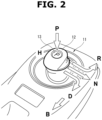
- the shift lever 12 has a home position (indicated by a reference numeral H in FIG. 2 ) in which the shift lever 12 stands almost vertically in the center, wherein the shift lever 12 is configured to mechanically return to the home position when forces of a palm and fingers are released after tilting in each direction.
- a corresponding switch is turned on.
- the switch is of a type performing so-called momentary operation. For example, regarding the N-range, an N-range signal indicating selection of the N-range is on, only while the shift lever 12 is tilted to the right.
- the range signal outputted from the range selector 11 by momentary operation is inputted to the shift controller 8, wherein the shift controller 8 processes the range signal and determines which range the driver has selected. For example, selection of each range other than shifting from the D-range to the B-range is required be performed along with depression of a brake pedal not shown. Selection of the P-range requires a condition that the vehicle is completely stopped in addition to a condition that the brake pedal is depressed. As shown in FIG. 1 , a brake signal and a vehicle speed signal are inputted to the shift controller 8 in order to determine whether the brake pedal is depressed and the vehicle is at rest. Near the range selector 11, a shift indicator 15 is provided for indicating a selected range position by lighting a small lamp, based on a signal (shift indicator output) outputted from the shift controller 8.
- the shift controller 8 is connected via a communication network (for example, CAN communication) to the vehicle controller 2 that controls the EV motor 1 actually. As shown in FIG. 1 , based on the input from the range selector 11, the shift controller 8 transmits a requested range signal to the vehicle controller 2. The vehicle controller 2 calculates a torque command to the EV motor 1 in a mode corresponding to the designated range position, based on the accelerator operation input described above. On the other hand, the vehicle controller 2 sends back to the shift controller 8 a vehicle actual range signal indicating the range position currently recognized by the vehicle controller 2. The shift controller 8 is configured to collate the requested range signal with the vehicle actual range signal, and thereby detect abnormality in a section related to these signals. The vehicle controller 2 also transmits to the shift controller 8 information on the accelerator operation input as accelerator operation information.
- a communication network for example, CAN communication
- the current range position is outputted by the vehicle controller 2 and indicated at an appropriate position on a display 16 in front of the driver's seat. In the example of FIG. 1 , it is indicated that it is currently in the P-range position.
- the display 16 includes not only an area for indication of the range position, but also an area of indication that is configured to indicate, by a character string or an image, guidance on N-range keeping operation, and that an N-range keeping mode is set, as detailed below.
- a buzzer 18 is arranged for warning or informing acoustically, and is connected to the vehicle controller 2.
- the vehicle controller 2 receives input of a signal from a starter switch 17 of a push button type.
- the starter switch 17 corresponds to a so-called key switch, and is used solely to perform key-on operation and key-off operation.
- This starter switch 17 is also of a momentary operation type, and outputs an on-signal only while being pressed.
- the vehicle controller 2 determines that key-on operation is performed, and when the on-signal of the starter switch 17 is inputted when in the key-on state, the vehicle controller 2 determines that key-off operation is performed.
- “key on” may be also referred to as "ignition on” or "IGN ON”
- key off may be also referred to as "ignition off” or "IGN OFF”.
- FIG. 3 is a time chart showing an example of behavior of the park lock control device configured as described above.
- the on/off state of the ignition In order from the top are arranged (a) the on/off state of the ignition, (b) the actual range position, (c) the range signal outputted by the range selector 11, (d) the signal of the starter switch 17, (e) the brake signal, (f) the presence/absence of indication on the display 16, (g) the on/off state of the buzzer, and (h) the state of an N-range keeping flag.
- This time chart starts under a condition where the ignition is on, and the vehicle is traveling in the D-range, B-range or R-range.
- the first half of the time chart shows behavior in which as a default setting, when the ignition is turned off while being in the N-range position, shifting into the P-range automatically occurs. Namely, when the traveling is finished, the brake signal is turned on, and the range signal to the N-range is inputted, the actual range position becomes the N-range at a time instant t1. Thereafter, when a driver presses the starter switch 17, the ignition is turned off at a time instant t2.
- the display 16 in front of the driver's seat indicates by a character string or an image that N-range keeping operation is possible which allows the vehicle to be parked without activation of the park lock mechanism 6, and indicates the guidance on the method of operation.
- the N-range keeping mode is set by continuously operating the shift lever 12 of the range selector 11 as "P -> N -> N". The guidance for such an operation is indicated on the display 16.
- the actual range position shifts from the N-range to the P-range according to the default setting.
- the shift into the P-range causes the park lock mechanism 6 to operate and lock the driving wheels 5.
- the vehicle is parked in the P-range with the park lock mechanism 6 activated.
- the guidance for the N-range keeping operation is presented until an appropriate time elapses, and then disappears.
- the guidance is set to disappear later than the shift to the P-range, in order to allow shifting to the N-range keeping mode even after the actual range position becomes the P-range and the park lock mechanism 6 is once activated.
- the time chart shows setting operation of the N-range keeping mode.
- the N-range keeping mode is set by operating the shift lever 12 of the range selector 11 continuously as "P -> N -> N" while the vehicle is stopped, the ignition is on, and the brake signal is on.
- the shift controller 8 determines that such a continuous input is a request for setting the N-range keeping mode. Therefore, the N-range keeping flag shown in row (h) is turned on (at a time instant t4).
- the display 16 indicates that the N-range keeping mode has been set, and the buzzer 18 sounds to warn the driver that the N-range keeping mode has been set.
- the starter switch 17 subsequent to operation of the shift lever 12, the ignition is turned off from the on-state at a time instant t5 as shown in row (a).
- the actual range position is shifted to the N-range by the first N-range signal, so that when the ignition is turned off, it is in the N-range position.
- the N-range keeping mode is set (namely, the N-range keeping flag is on), no automatic shifting to the P-range is performed.
- the park lock mechanism 6 also remains inactive. Therefore, it is possible to park the vehicle in the N-range where the vehicle can be slightly moved by human power.
- the indication on the display 16 and the sound of the buzzer 18 continue for an appropriate time from the ignition-off operation, and then terminate. This is to prevent the driver from leaving the vehicle while misunderstanding that the park lock mechanism 6 is operating.
- the N-range keeping flag is basically turned off, namely, the N-range keeping mode is canceled.
- the range keeping mode is not released by ignition-on operation.
- the shift lever 12 is continuously operated as "P -> N -> N"
- the N-range keeping mode is customized and is not canceled by subsequent ignition-on operation.
- the customized setting of the N-range keeping mode is canceled when the driver operates the shift lever 12 into the P-range (actually, pressing the button 13 for the P-range).
- FIGS. 4 to 6 show a main flowchart divided into three, and the main flowchart is repeatedly executed by the shift controller 8 at predetermined calculation cycles, for example. Symbols used in the drawings are as follows.
- Step 1 each step is abbreviated as S1 etc. in the drawings
- the controllers are energized, for example, when a door is released from locking or the door is opened.
- Step 4 it is determined whether the ignition is on. When the ignition is not on, the process returns to Step 1.
- Step 5 it is determined whether the N-range keeping customization setting flag is equal to 1.
- Step 6 the N-range keeping flag is reset to 0. Thereby, the N-range keeping mode is to be canceled when the ignition is turned on, as described above.
- Step 7 it is determined at Step 7 whether the N-range keeping flag at this moment is equal to 1.
- the process proceeds to a subroutine of Step 8.
- the process proceeds to a subroutine of Step 9.
- the subroutine of Step 8 is a process of determining whether the driver intends to keep the N-range.
- the subroutine of Step 9 is a process of determining the necessity of canceling the N-range keeping.
- Step 10 it is determined whether the N-range keeping flag is equal to 1 after the subroutines.
- the process proceeds to Step 11.
- the N-range keeping flag is equal to 0, the process proceeds to Step 24 in FIG. 5 .
- Step 11 it is determined whether the N-range keeping customization setting flag is equal to 1.
- the process proceeds to Step 21 in FIG. 5 .
- the process proceeds to Step 12 in FIG. 5 .
- Step 12 it is determined whether a count value of the display-buzzer timer exceeds a predetermined time (xx seconds). In case of NO, at Step 13, the N-range keeping display flag and the N-range keeping buzzer flag are set to 1. Then, at Step 14, the display 16 is caused to indicate that the N-range keeping mode is set, and the buzzer 18 is caused to sound.
- Step 12 When the count value of the display-buzzer timer exceeds the predetermined time (xx seconds) at Step 12, the process proceeds to Step 15 where the display-buzzer timer is stopped, and proceeds to Steps 16 and 17 where the N-range keeping display flag and the N-range keeping flag are set to 0. Thereby, the indication on the display 16 and the buzzer 18 are stopped.
- the predetermined time (xx seconds) is changeable and appropriately set.
- the indication on the display 16 and the warning by the buzzer 18 may be configured to continue while the ignition is on.
- Step 18 it is determined whether or not the driver has performed the customization setting operation of the N-range keeping.
- the customization setting operation of the N-range keeping when the shift lever 12 is operated continuously as "P -> N -> N", the last N-range signal is outputted for a long time (namely, the shift lever 12 is held at the N-range position for a predetermined time).
- the customization setting operation may be implemented by a specific operation other than this example.
- Step 18 When the customization setting operation is performed, the process proceeds from Step 18 to Step 19 where the N-range keeping customization setting flag is set to 1. When no customization setting operation is performed, the process proceeds from Step 18 to Step 20 where the N-range keeping customization setting flag is set to 0.
- Step 11 when the N-range keeping customization setting flag is already set to 1 at Step 11 described above, the process proceeds from Step 11 to Step 21 where it is determined whether or not the driver has canceled the N-range keeping customization setting.
- pressing the P-range button 13 of the shift lever 12 is an example of operation of cancelling the N-range keeping customization setting.
- the operation of cancellation of the customization setting may be implemented by a specific operation other than this example.
- Step 21 When no cancellation operation of the customization setting is performed, the process proceeds from Step 21 to Step 22 where the N-range keeping customization setting flag is maintained at 1.
- Step 21 to Step 23 When the operation to cancel the customization setting is performed, the process proceeds from Step 21 to Step 23 where the N-range keeping customization setting flag is set to 0.
- Step 10 When the N-range keeping flag is equal to 0 at Step 10 described above, the process proceeds to Step 24 where the N-range keeping customization setting flag at the moment is held.
- Step 25 After processing the N-range keeping customization setting flag at Steps 19, 20, 22, 23, and 24, the process proceeds to Step 25 where it is determined whether the ignition is off. In case of NO, the process returns to Step 7. Accordingly, the process of Steps 7 to 25 is basically repeated from ignition-on operation to ignition-off operation.
- Step 25 When it is determined at Step 25 that the ignition is off, the process proceeds to Step 26 where it is determined whether or not the N-range keeping flag is equal to 1.
- the process proceeds to Step 27 where the N-range keeping display flag is set to 0.
- the N-range keeping guidance flag is set to 1, and based on this flag, the guidance for setting the N-range keeping mode is indicated on the display 16 (Steps 28 and 29). Namely, for example, the driver is informed that the N-range keeping mode can be set by the operation of "P -> N - > N".
- Step 30 automatic shifting to the P-range is performed, and proceeds to Step 31 where it is determined whether or not the shifting to the P-range is completed.
- Step 32 the N-range keeping guidance flag is set to 0. Accordingly, the indication of the guidance on the display 16 terminates.
- the indication of the N-range keeping guidance may be configured to continue for a while after the shift to the P-range. With the shift to the P-range, the park lock mechanism 6 is activated.
- Step 33 the value of the N-range keeping flag at that time is stored as the N-range keeping flag previous trip value (bNKPON_bkup), and the overall process is terminated.
- Step 34 the N-range is maintained without automatic shift to the P-range. Namely, the N-range is maintained without activation of the park lock mechanism 6.
- Step 35 the N-range keeping display flag and the N-range keeping buzzer flag are set to 0 after a predetermined time has elapsed from the ignition-off operation (for example, 5 seconds later).
- the indication that the N-range keeping mode is set and the buzzer 18 are stopped (Step 36). Namely, when the ignition is turned off while the N-range position is maintained in the N-range keeping mode, the indication that the N-range keeping mode is set and the buzzer 18 are stopped 5 seconds after the ignition is turned off.
- Step 33 the value of the N-range keeping flag at that time is stored as the N-range keeping flag previous trip value (bNKPON_bkup), and the overall process is terminated.
- This subroutine is a process of determining driver's intention to keep the N-range when the N-range keeping flag is equal to 0 at Step 7.
- Step 41 it is determined whether the brake signal is on and the P-range signal is on. This corresponds to the first operation to the "P-range" in the series of operations "P -> N -> N” according to the embodiment.
- Step 41 When the determination at Step 41 is YES, the process proceeds to Step 42 where counting of the N-range keeping determination permission timer is started.
- Step 43 it is determined whether the brake signal is on, the N-range signal is on, and the count value of the N-range keeping determination permission timer is less than or equal to a predetermined time (for example, 5 seconds). This corresponds to determination as to whether or not the first operation to the "N-range” in the series of operations of "P - > N -> N" is performed within 5 seconds from the operation to the P-range.
- a predetermined time for example, 5 seconds
- Step 44 it is determined whether the brake signal is on, the N-range signal is on, and the count value of the N-range keeping determination permission timer is less than or equal to a predetermined time (for example, 5 seconds). This corresponds to determination as to whether or not the second operation to the "N-range" in the series of operations of "P -> N -> N” is performed within 5 seconds from the operation to the P-range.
- a predetermined time for example, 5 seconds
- Step 44 When the determination at Step 44 is YES, it means that the operation of "P -> N -> N" is continuously executed within 5 seconds as a whole, and the process proceeds to Step 45 where the N-range keeping flag is set to 1. Then, at Step 46, counting of the display-buzzer timer is started. The processing of Step 12 and others described above is performed based on the count value of this display-buzzer timer.
- Step 41 determines whether the determination at Step 41, Step 43, and Step 44 is NO. If any of the determination at Step 41, Step 43, and Step 44 is NO, the process proceeds to Step 48 where the N-range keeping flag is set to 0. Then, at Step 49, the value of the display-buzzer timer is reset to 0.
- Step 47 the N-range keeping determination permission timer is stopped, the count value thereof is reset to 0, and the subroutine is terminated.
- This subroutine is a process of determining whether or not it is required to cancel the N-range keeping when the N-range keeping flag is equal to 1 at Step 7.
- Step 51 it is determined whether the N-range keeping customization setting flag is equal to 1.
- the N-range keeping customization setting flag is equal to 1
- the process proceeds to Step 53 where the value of the N-range keeping flag is held as it is. In other words, the N-range keeping flag remains to be equal to 1.
- the count value of the display-buzzer timer is held as it is (Step 54).
- Step 55 it is determined whether or not the P-range operation (the operation of pressing the P-range button 13) is performed.
- the process further proceeds to Step 56 where it is determined whether or not operation has been made to a traveling range other than the N-range (in this embodiment, this traveling range corresponds to the D-range, the B-range, and the R-range).
- Step 56 it is determined whether or not operation has been made to a traveling range other than the N-range (in this embodiment, this traveling range corresponds to the D-range, the B-range, and the R-range).
- Step 52 the operation described above.
- Step 55 the process proceeds to Step 57 where the N-range keeping flag is reset to 0. Then, the display-buzzer timer is reset to 0.
- the P-range is automatically set to operate the park lock mechanism 6.
- the guidance on the possibility of setting the N-range keeping mode and the method thereof is indicated. Simultaneously, this guidance also informs the driver that the ignition is turned off by the driver when in the N-range instead of the P-range.
- the N-range keeping mode is set to allow parking in the N-range. Namely, the park lock mechanism 6 is not activated even when the ignition is turned off. At this time, the indication on the display 16 and the buzzer 18 warn that the N-range keeping mode is set, namely, the park lock mechanism 6 is not operating.
- the N-range keeping mode can be set as a customized setting of the vehicle, and the N-range keeping mode is not canceled at the next ignition-on operation. It is convenient for users who want to always keep the N-range when parking, because the customized setting of the vehicle serves to eliminate the necessity of each operation of setting the N-range keeping mode.
- the present invention is not limited to electric vehicles, but may be applied widely to vehicles each having an internal combustion engine as a drive source, or hybrid vehicles each having an internal combustion engine and an electric motor as a drive source.
- the range selector and the ignition key switch are not limited to the types of the above-described embodiment, but may be of any publicly known type.
- the existing shift lever 12 is used for the N-range keeping mode setting, the vehicle customization setting, and cancellation of the vehicle customization setting.
- dedicated switches or the like may be provided.
- the setting operation of the N-range keeping mode may be implemented not only by the above-mentioned operation "P -> N -> N", but also may be implemented variously with existing devices, for example, by shifting to the N-range while depressing the brake with no driving torque generated, and thereafter holding accelerator operation for a certain period of time. The same applies to the vehicle customization setting and its cancellation.
Claims (5)
- Fahrzeug-Parksperren-Steuerverfahren mit einem Bereichswähler (11), der zur Auswahl von Bereichspositionen vorgesehen ist, die eine P-Bereichsposition und eine N-Bereichsposition aufweisen, in denen jeweils verhindert wird, dass eine Antriebskraft auf ein Antriebsrad (5) des Fahrzeugs übertragen wird, wobei der Bereichswähler einen Bereichswählhebel (12) aufweist, der angeordnet ist, um mechanisch in eine Ausgangsposition zurückgeführt zu werden, wobei ein Parksperrmechanismus (6) aktiviert wird, wenn die P-Bereichsposition durch den Bereichswähler (11) ausgewählt wird, wobei das Fahrzeug-Parksperren-Steuerverfahren aufweist:Ermöglichen, dass ein Bediener auswählt, ob zu bewirken oder nicht, dass der Parksperrmechanismus (6) in Reaktion auf Schlüssel-Aus-Betätigung aktiviert wird, wenn in der N-Bereichsposition (6); undBereitstellen eines N-Bereich-Halte-Modus, wobei der N-Bereich-Halte-Modus durch eine vorbestimmte N-Bereich-Halte-Betätigung des Bedieners aktiviert wird; undin Reaktion auf Aktivierung des N-Bereich-Halte-Modus, Verhindern, dass der Parksperrmechanismus (6) in Reaktion auf Schlüssel-Aus-Betätigung aktiviert wird, wenn in der N-Bereichsposition,dadurch gekennzeichnet, dassin Reaktion auf Schlüssel-Aus-Betätigung in der N-Bereichsposition ohne aktivierten N-Bereich-Halte-Modus, Anzeigen einer Anleitung für die N-Bereich-Halte-Betätigung auf einer Anzeige (16) des Fahrzeugs; undImplementieren der N-Bereich-Halte-Betätigung durch Schalten des Bereichswahlhebels (12) nach einem vorbestimmten Muster von einer Ausgangsposition in eine Mehrzahl von spezifischen der Bereichspositionen.
- Fahrzeug-Parksperren-Steuerverfahren nach Anspruch 1, dadurch gekennzeichnet ferner durch:
Deaktivieren des N-Bereich-Halte-Modus in Reaktion auf eine nächste Schlüssel-Ein-Betätigung. - Fahrzeug-Parksperren-Steuerverfahren nach Anspruch 2, dadurch gekennzeichnet ferner durch:
in Reaktion auf eine vorbestimmte Betätigung des Bedieners, Einrichten einer Fahrzeuganpassungseinstellung, um zu verhindern, dass der N-Bereich-Halte-Modus in Reaktion auf die nächste Schlüssel-Ein-Betätigung deaktiviert wird. - Fahrzeug-Parksperren-Steuerverfahren nach Anspruch 1, dadurch gekennzeichnet ferner durch:
in Reaktion auf Auswählen des N-Bereich-Halte-Modus, visuelles oder akustisches Informieren des Bedieners über die Auswahl des N-Bereich-Halte-Modus . - Fahrzeug-Parksperren-Steuervorrichtung, umfassend:einen Bereichswähler (11), der zum Auswählen von Bereichspositionen vorgesehen ist, die eine P-Bereich-Position und eine N-Bereich-Position umfassen, in denen jeweils verhindert wird, dass eine Antriebskraft auf ein Antriebsrad (5) übertragen wird, das ein Straßenrad eines Fahrzeugs darstellt, wobei der Bereichswähler einen Bereichswählhebel (12) aufweist, der angeordnet ist, um mechanisch in eine Ausgangsposition zurückgeführt zu werden; undeinen Parksperrmechanismus (6), der eingerichtet ist, um mindestens ein Straßenrad (5) zu sperren;wobei die Fahrzeug-Parksperren-Steuervorrichtung konfiguriert ist, dass der Parksperrmechanismus (6) aktiviert wird, wenn die P-Bereich-Position durch den Bereichswähler (11) ausgewählt wird;wobei ein Bediener auswählen kann, ob der Parksperrmechanismus (6) in Reaktion auf eine Schlüssel-Aus-Betätigung bewirkt werden soll oder nicht, wenn in der N-Bereich-Position; undein N-Bereich-Halte-Modus vorgesehen ist, wobei der N-Bereich-Halte-Modus durch eine vorbestimmte N-Bereich-Halte-Betätigung des Bedieners aktiviert wird; undin Reaktion auf Aktivierung des N-Bereich-Halte-Modus verhindert wird, dass der Parksperrmechanismus (6) in Reaktion auf Schlüssel-Aus-Betätigung aktiviert wird, wenn in der N-Bereich-Position;dadurch gekennzeichnet, dass die Fahrzeug-Parksperren-Steuervorrichtung ferner konfiguriert ist, sodassin Reaktion auf eine Schlüssel-Aus-Betätigung, wenn in der N-Bereich-Position ohne aktivierten N-Bereich-Halte-Modus, Anleitung für die N-Bereich-Halte-Betätigung auf einem Display (16) des Fahrzeugs angezeigt wird; unddie N-Bereich-Halte-Betätigung implementiert wird durch Schalten des Bereichswählhebels (12) nach einem vorbestimmten Muster von einer Ausgangsposition in eine Mehrzahl von spezifischen der Bereichspositionen.
Applications Claiming Priority (1)
| Application Number | Priority Date | Filing Date | Title |
|---|---|---|---|
| PCT/JP2019/051191 WO2021130974A1 (ja) | 2019-12-26 | 2019-12-26 | 車両のパークロック制御方法およびパークロック制御装置 |
Publications (3)
| Publication Number | Publication Date |
|---|---|
| EP4083475A1 EP4083475A1 (de) | 2022-11-02 |
| EP4083475A4 EP4083475A4 (de) | 2022-12-07 |
| EP4083475B1 true EP4083475B1 (de) | 2023-11-15 |
Family
ID=76575848
Family Applications (1)
| Application Number | Title | Priority Date | Filing Date |
|---|---|---|---|
| EP19957346.0A Active EP4083475B1 (de) | 2019-12-26 | 2019-12-26 | Verfahren und vorrichtung zur steuerung der parksperre eines fahrzeugs |
Country Status (5)
| Country | Link |
|---|---|
| US (1) | US20230032865A1 (de) |
| EP (1) | EP4083475B1 (de) |
| JP (1) | JP7447917B2 (de) |
| CN (1) | CN114867955A (de) |
| WO (1) | WO2021130974A1 (de) |
Families Citing this family (1)
| Publication number | Priority date | Publication date | Assignee | Title |
|---|---|---|---|---|
| CN113335078A (zh) * | 2021-07-20 | 2021-09-03 | 中国第一汽车股份有限公司 | 一种p挡驻车监控方法、监控系统和电动汽车 |
Family Cites Families (19)
| Publication number | Priority date | Publication date | Assignee | Title |
|---|---|---|---|---|
| DE19625019A1 (de) * | 1996-06-22 | 1998-01-02 | Bayerische Motoren Werke Ag | Kraftfahrzeug mit automatisch geschaltetem Getriebe |
| JP2004324849A (ja) | 2003-04-28 | 2004-11-18 | Nissan Motor Co Ltd | シフトバイワイヤ式自動変速機のレンジ切り換え制御装置 |
| DE102007040904B4 (de) * | 2007-08-30 | 2011-06-22 | ZF Friedrichshafen AG, 88046 | Verfahren zur Ansteuerung der Neutralposition in einem automatischen oder automatisierten Getriebe eines Kraftfahrzeugs |
| DE102007000558B3 (de) * | 2007-10-24 | 2009-06-04 | Zf Friedrichshafen Ag | Verfahren zum Ansteuern einer Neutralposition eines Kfz-Getriebes und zum Ansteuern einer Parkvorrichtung des Kraftfahrzeugs |
| JP4837754B2 (ja) * | 2009-02-17 | 2011-12-14 | ジヤトコ株式会社 | シフトバイワイヤ式車両の制御装置 |
| JP4920732B2 (ja) * | 2009-09-30 | 2012-04-18 | ジヤトコ株式会社 | シフトバイワイヤ式車両の制御装置 |
| US9091340B2 (en) * | 2011-05-11 | 2015-07-28 | GM Global Technology Operations LLC | Latching shifter with override feature |
| US8897978B2 (en) * | 2011-12-09 | 2014-11-25 | Ford Global Technologies, Llc | Method and system for providing a neutral hold mode in a shift-by-wire transmission |
| US8634995B2 (en) * | 2011-12-09 | 2014-01-21 | Ford Global Technologies, Llc | Method and system for providing a voting strategy for determining a mode state in a shift-by-wire transmission |
| WO2015016109A1 (ja) * | 2013-08-02 | 2015-02-05 | 本田技研工業株式会社 | 車両の制御装置及び制御方法 |
| KR101575414B1 (ko) * | 2013-11-18 | 2015-12-21 | 현대자동차주식회사 | 차량의 변속 장치 |
| US9726284B2 (en) * | 2015-04-30 | 2017-08-08 | Honda Motor Co., Ltd. | Neutral-hold mode system and method |
| US9714706B1 (en) * | 2016-06-20 | 2017-07-25 | Ford Global Technologies, Llc | Driver interface with inferred park logic |
| US10443725B2 (en) * | 2016-09-01 | 2019-10-15 | Ford Global Technologies, Llc | Shift-by-wire module illumination strategy for vehicle |
| JP2019070394A (ja) * | 2017-10-06 | 2019-05-09 | スズキ株式会社 | 車両の制御装置 |
| JP6935753B2 (ja) * | 2018-01-19 | 2021-09-15 | トヨタ自動車株式会社 | 車両の制御装置 |
| JP2019138316A (ja) * | 2018-02-06 | 2019-08-22 | トヨタ自動車株式会社 | 車両制御装置 |
| CN110271519B (zh) * | 2019-06-11 | 2021-04-13 | 浙江吉利控股集团有限公司 | 一种自动驻车系统和方法及车辆 |
| US11384832B1 (en) * | 2021-04-02 | 2022-07-12 | Honda Motor Co., Ltd. | System and method for neutral transmission hold |
-
2019
- 2019-12-26 EP EP19957346.0A patent/EP4083475B1/de active Active
- 2019-12-26 JP JP2021566693A patent/JP7447917B2/ja active Active
- 2019-12-26 WO PCT/JP2019/051191 patent/WO2021130974A1/ja unknown
- 2019-12-26 US US17/788,804 patent/US20230032865A1/en active Pending
- 2019-12-26 CN CN201980103286.7A patent/CN114867955A/zh active Pending
Also Published As
| Publication number | Publication date |
|---|---|
| EP4083475A1 (de) | 2022-11-02 |
| EP4083475A4 (de) | 2022-12-07 |
| JPWO2021130974A1 (de) | 2021-07-01 |
| US20230032865A1 (en) | 2023-02-02 |
| JP7447917B2 (ja) | 2024-03-12 |
| CN114867955A (zh) | 2022-08-05 |
| WO2021130974A1 (ja) | 2021-07-01 |
Similar Documents
| Publication | Publication Date | Title |
|---|---|---|
| JP4179388B1 (ja) | 車両用制御装置 | |
| US7451845B2 (en) | Adjustment of the speed of a motor vehicle with an automatic gearbox | |
| US6699155B2 (en) | Vehicle transmission controller | |
| US5984828A (en) | Control methods for a shift by wire vehicle transmission | |
| JP4668226B2 (ja) | 車両制御システム | |
| EP1845495B1 (de) | Elektrisches Parkbremsensystem | |
| EP2683587B1 (de) | Fahrer auswählbare langsame modus zur deaktivierung der stop / start | |
| JP2007170546A (ja) | 車両制御システム | |
| US9309966B2 (en) | Method of controlling vehicle washing mode for vehicle equipped with shift-by-wire shifting device | |
| EP4083475B1 (de) | Verfahren und vorrichtung zur steuerung der parksperre eines fahrzeugs | |
| JP2010173607A (ja) | 車両制御システム | |
| US6612966B2 (en) | Vehicle securing system | |
| JP5234309B2 (ja) | 変速制御装置 | |
| JP2017075631A (ja) | 駐車制御装置 | |
| US11415214B2 (en) | Shift operation determination apparatus and shift apparatus | |
| US11708894B2 (en) | Shift apparatus and control method of shift apparatus | |
| JP2022152515A (ja) | 車両の制御装置 | |
| JPS61150841A (ja) | 自動トランスミツシヨン | |
| JPS63251330A (ja) | 歯車変速機の自動変速装置 | |
| JPH05229365A (ja) | 自動変速機の変速制御装置 | |
| JPH04327060A (ja) | 変速装置 | |
| KR930012432A (ko) | 수동, 자동 겸용의 차량변속, 제어장치 및 그 제어방법 |
Legal Events
| Date | Code | Title | Description |
|---|---|---|---|
| STAA | Information on the status of an ep patent application or granted ep patent |
Free format text: STATUS: THE INTERNATIONAL PUBLICATION HAS BEEN MADE |
|
| PUAI | Public reference made under article 153(3) epc to a published international application that has entered the european phase |
Free format text: ORIGINAL CODE: 0009012 |
|
| STAA | Information on the status of an ep patent application or granted ep patent |
Free format text: STATUS: REQUEST FOR EXAMINATION WAS MADE |
|
| 17P | Request for examination filed |
Effective date: 20220627 |
|
| AK | Designated contracting states |
Kind code of ref document: A1 Designated state(s): AL AT BE BG CH CY CZ DE DK EE ES FI FR GB GR HR HU IE IS IT LI LT LU LV MC MK MT NL NO PL PT RO RS SE SI SK SM TR |
|
| A4 | Supplementary search report drawn up and despatched |
Effective date: 20221108 |
|
| RIC1 | Information provided on ipc code assigned before grant |
Ipc: F16H 59/74 20060101ALN20221102BHEP Ipc: F16H 59/02 20060101ALN20221102BHEP Ipc: F16H 59/10 20060101ALN20221102BHEP Ipc: F16H 63/48 20060101ALI20221102BHEP Ipc: F16H 63/42 20060101ALI20221102BHEP Ipc: F16H 61/16 20060101ALI20221102BHEP Ipc: B60T 8/17 20060101ALI20221102BHEP Ipc: F16H 63/34 20060101AFI20221102BHEP |
|
| DAV | Request for validation of the european patent (deleted) | ||
| DAX | Request for extension of the european patent (deleted) | ||
| STAA | Information on the status of an ep patent application or granted ep patent |
Free format text: STATUS: EXAMINATION IS IN PROGRESS |
|
| 17Q | First examination report despatched |
Effective date: 20230623 |
|
| GRAP | Despatch of communication of intention to grant a patent |
Free format text: ORIGINAL CODE: EPIDOSNIGR1 |
|
| STAA | Information on the status of an ep patent application or granted ep patent |
Free format text: STATUS: GRANT OF PATENT IS INTENDED |
|
| RIC1 | Information provided on ipc code assigned before grant |
Ipc: F16H 59/74 20060101ALN20230731BHEP Ipc: F16H 59/02 20060101ALN20230731BHEP Ipc: F16H 59/10 20060101ALN20230731BHEP Ipc: F16H 63/48 20060101ALI20230731BHEP Ipc: F16H 63/42 20060101ALI20230731BHEP Ipc: F16H 61/16 20060101ALI20230731BHEP Ipc: B60T 8/17 20060101ALI20230731BHEP Ipc: F16H 63/34 20060101AFI20230731BHEP |
|
| RIC1 | Information provided on ipc code assigned before grant |
Ipc: F16H 59/74 20060101ALN20230824BHEP Ipc: F16H 59/02 20060101ALN20230824BHEP Ipc: F16H 59/10 20060101ALN20230824BHEP Ipc: F16H 63/48 20060101ALI20230824BHEP Ipc: F16H 63/42 20060101ALI20230824BHEP Ipc: F16H 61/16 20060101ALI20230824BHEP Ipc: B60T 8/17 20060101ALI20230824BHEP Ipc: F16H 63/34 20060101AFI20230824BHEP |
|
| INTG | Intention to grant announced |
Effective date: 20230906 |
|
| GRAS | Grant fee paid |
Free format text: ORIGINAL CODE: EPIDOSNIGR3 |
|
| GRAA | (expected) grant |
Free format text: ORIGINAL CODE: 0009210 |
|
| STAA | Information on the status of an ep patent application or granted ep patent |
Free format text: STATUS: THE PATENT HAS BEEN GRANTED |
|
| AK | Designated contracting states |
Kind code of ref document: B1 Designated state(s): AL AT BE BG CH CY CZ DE DK EE ES FI FR GB GR HR HU IE IS IT LI LT LU LV MC MK MT NL NO PL PT RO RS SE SI SK SM TR |
|
| REG | Reference to a national code |
Ref country code: CH Ref legal event code: EP Ref country code: GB Ref legal event code: FG4D |
|
| REG | Reference to a national code |
Ref country code: DE Ref legal event code: R096 Ref document number: 602019041732 Country of ref document: DE |
|
| REG | Reference to a national code |
Ref country code: IE Ref legal event code: FG4D |
|
| PGFP | Annual fee paid to national office [announced via postgrant information from national office to epo] |
Ref country code: GB Payment date: 20231115 Year of fee payment: 5 |
|
| PGFP | Annual fee paid to national office [announced via postgrant information from national office to epo] |
Ref country code: FR Payment date: 20231108 Year of fee payment: 5 Ref country code: DE Payment date: 20231031 Year of fee payment: 5 |
|
| REG | Reference to a national code |
Ref country code: LT Ref legal event code: MG9D |
|
| REG | Reference to a national code |
Ref country code: NL Ref legal event code: MP Effective date: 20231115 |
|
| PG25 | Lapsed in a contracting state [announced via postgrant information from national office to epo] |
Ref country code: GR Free format text: LAPSE BECAUSE OF FAILURE TO SUBMIT A TRANSLATION OF THE DESCRIPTION OR TO PAY THE FEE WITHIN THE PRESCRIBED TIME-LIMIT Effective date: 20240216 |
|
| PG25 | Lapsed in a contracting state [announced via postgrant information from national office to epo] |
Ref country code: IS Free format text: LAPSE BECAUSE OF FAILURE TO SUBMIT A TRANSLATION OF THE DESCRIPTION OR TO PAY THE FEE WITHIN THE PRESCRIBED TIME-LIMIT Effective date: 20240315 |
|
| PG25 | Lapsed in a contracting state [announced via postgrant information from national office to epo] |
Ref country code: LT Free format text: LAPSE BECAUSE OF FAILURE TO SUBMIT A TRANSLATION OF THE DESCRIPTION OR TO PAY THE FEE WITHIN THE PRESCRIBED TIME-LIMIT Effective date: 20231115 |
|
| REG | Reference to a national code |
Ref country code: AT Ref legal event code: MK05 Ref document number: 1632054 Country of ref document: AT Kind code of ref document: T Effective date: 20231115 |
|
| PG25 | Lapsed in a contracting state [announced via postgrant information from national office to epo] |
Ref country code: NL Free format text: LAPSE BECAUSE OF FAILURE TO SUBMIT A TRANSLATION OF THE DESCRIPTION OR TO PAY THE FEE WITHIN THE PRESCRIBED TIME-LIMIT Effective date: 20231115 |
|
| PG25 | Lapsed in a contracting state [announced via postgrant information from national office to epo] |
Ref country code: AT Free format text: LAPSE BECAUSE OF FAILURE TO SUBMIT A TRANSLATION OF THE DESCRIPTION OR TO PAY THE FEE WITHIN THE PRESCRIBED TIME-LIMIT Effective date: 20231115 |
|
| PG25 | Lapsed in a contracting state [announced via postgrant information from national office to epo] |
Ref country code: ES Free format text: LAPSE BECAUSE OF FAILURE TO SUBMIT A TRANSLATION OF THE DESCRIPTION OR TO PAY THE FEE WITHIN THE PRESCRIBED TIME-LIMIT Effective date: 20231115 |
|
| PG25 | Lapsed in a contracting state [announced via postgrant information from national office to epo] |
Ref country code: NL Free format text: LAPSE BECAUSE OF FAILURE TO SUBMIT A TRANSLATION OF THE DESCRIPTION OR TO PAY THE FEE WITHIN THE PRESCRIBED TIME-LIMIT Effective date: 20231115 Ref country code: LT Free format text: LAPSE BECAUSE OF FAILURE TO SUBMIT A TRANSLATION OF THE DESCRIPTION OR TO PAY THE FEE WITHIN THE PRESCRIBED TIME-LIMIT Effective date: 20231115 Ref country code: IS Free format text: LAPSE BECAUSE OF FAILURE TO SUBMIT A TRANSLATION OF THE DESCRIPTION OR TO PAY THE FEE WITHIN THE PRESCRIBED TIME-LIMIT Effective date: 20240315 Ref country code: GR Free format text: LAPSE BECAUSE OF FAILURE TO SUBMIT A TRANSLATION OF THE DESCRIPTION OR TO PAY THE FEE WITHIN THE PRESCRIBED TIME-LIMIT Effective date: 20240216 Ref country code: ES Free format text: LAPSE BECAUSE OF FAILURE TO SUBMIT A TRANSLATION OF THE DESCRIPTION OR TO PAY THE FEE WITHIN THE PRESCRIBED TIME-LIMIT Effective date: 20231115 Ref country code: BG Free format text: LAPSE BECAUSE OF FAILURE TO SUBMIT A TRANSLATION OF THE DESCRIPTION OR TO PAY THE FEE WITHIN THE PRESCRIBED TIME-LIMIT Effective date: 20240215 Ref country code: AT Free format text: LAPSE BECAUSE OF FAILURE TO SUBMIT A TRANSLATION OF THE DESCRIPTION OR TO PAY THE FEE WITHIN THE PRESCRIBED TIME-LIMIT Effective date: 20231115 Ref country code: PT Free format text: LAPSE BECAUSE OF FAILURE TO SUBMIT A TRANSLATION OF THE DESCRIPTION OR TO PAY THE FEE WITHIN THE PRESCRIBED TIME-LIMIT Effective date: 20240315 |