EP4082877B1 - Fahrzeugluftreifen für die forstwirtschaft - Google Patents
Fahrzeugluftreifen für die forstwirtschaft Download PDFInfo
- Publication number
- EP4082877B1 EP4082877B1 EP22178788.0A EP22178788A EP4082877B1 EP 4082877 B1 EP4082877 B1 EP 4082877B1 EP 22178788 A EP22178788 A EP 22178788A EP 4082877 B1 EP4082877 B1 EP 4082877B1
- Authority
- EP
- European Patent Office
- Prior art keywords
- tread
- section
- tyre
- elevated
- primary
- Prior art date
- Legal status (The legal status is an assumption and is not a legal conclusion. Google has not performed a legal analysis and makes no representation as to the accuracy of the status listed.)
- Active
Links
Images


Classifications
-
- B—PERFORMING OPERATIONS; TRANSPORTING
- B60—VEHICLES IN GENERAL
- B60C—VEHICLE TYRES; TYRE INFLATION; TYRE CHANGING; CONNECTING VALVES TO INFLATABLE ELASTIC BODIES IN GENERAL; DEVICES OR ARRANGEMENTS RELATED TO TYRES
- B60C11/00—Tyre tread bands; Tread patterns; Anti-skid inserts
- B60C11/03—Tread patterns
- B60C11/0311—Patterns comprising tread lugs arranged parallel or oblique to the axis of rotation
- B60C11/0316—Patterns comprising tread lugs arranged parallel or oblique to the axis of rotation further characterised by the groove cross-section
-
- B—PERFORMING OPERATIONS; TRANSPORTING
- B62—LAND VEHICLES FOR TRAVELLING OTHERWISE THAN ON RAILS
- B62D—MOTOR VEHICLES; TRAILERS
- B62D55/00—Endless track vehicles
- B62D55/04—Endless track vehicles with tracks and alternative ground wheels, e.g. changeable from endless track vehicle into wheeled vehicle and vice versa
-
- B—PERFORMING OPERATIONS; TRANSPORTING
- B60—VEHICLES IN GENERAL
- B60C—VEHICLE TYRES; TYRE INFLATION; TYRE CHANGING; CONNECTING VALVES TO INFLATABLE ELASTIC BODIES IN GENERAL; DEVICES OR ARRANGEMENTS RELATED TO TYRES
- B60C11/00—Tyre tread bands; Tread patterns; Anti-skid inserts
- B60C11/03—Tread patterns
- B60C11/0311—Patterns comprising tread lugs arranged parallel or oblique to the axis of rotation
- B60C2011/0313—Patterns comprising tread lugs arranged parallel or oblique to the axis of rotation directional type
-
- B—PERFORMING OPERATIONS; TRANSPORTING
- B60—VEHICLES IN GENERAL
- B60C—VEHICLE TYRES; TYRE INFLATION; TYRE CHANGING; CONNECTING VALVES TO INFLATABLE ELASTIC BODIES IN GENERAL; DEVICES OR ARRANGEMENTS RELATED TO TYRES
- B60C2200/00—Tyres specially adapted for particular applications
- B60C2200/08—Tyres specially adapted for particular applications for agricultural vehicles
Definitions
- the invention to be presented relates to a pneumatic tyre for forestry use.
- the invention to be presented relates further to forestry machine having the pneumatic tyre.
- the invention to be presented relates further to a method of installing the pneumatic tyre onto a forestry machine.
- Pneumatic tyres applied in forestry, especially in forestry machines are used in severe off-road conditions in which the tyre is subject to damages caused by rough terrain, stones, tree stumps and logging waste removed from felled trees. Additionally, a continuous track installed on the tyre wears down the tyre and the tyre is subject to damages caused by the track that is dislocated and forced to move on the tyre in such a way that projecting parts of the track may damage the tyre or the track is not optimally placed on the tyre. Not only the track is used to improve the traction capability of tyre but alternatively also a tyre chain may be in use. The tyre chain wears down the tyre and may be dislocated when the tyre is used in rough terrain.
- a pneumatic tyre suitable for forestry use and applied in forestry machines is shown in EP 3412475 A1 .
- a track suitable for use with pneumatic tyres is shown in WO 2019/016430 A1 .
- Pneumatic tyres for agricultural use are disclosed in WO 2011/094828 A1 and JP H06320915 A .
- Another pneumatic tyre for forestry use, which is prior art according to Article 54(3) EPC, is known from EP 3738791 A1 .
- a pneumatic tyre for forestry use according to the preamble of claim 1 is disclosed in WO 2015/015525 A1 .
- the pneumatic tyre for forestry use according to the invention is presented in claim 1.
- the forestry machine according to the invention is presented in claim 12.
- the method of installing tyres onto a forestry machine according to the invention is presented in claim 13.
- the pneumatic tyre for forestry use comprises a ground-engaging tread section extending around the tyre in the circumferential direction of the tyre, the tread section defining an imaginary equatorial plane that is perpendicular to an axial direction of the tyre and passes through a centre region of the tread section; a pair of bead sections, located on two opposite sides of the tyre; a pair of sidewall sections, located on two opposite sides of the tyre, wherein each sidewall section extends between the respective bead section and the tread section, and wherein the tread section defines a pair of shoulder regions adjacent to the respective sidewall section.
- the tread section comprises a tread block row on both sides of the equatorial plane and each tread block row extends in the circumferential direction.
- Each tread block row comprises a series of primary tread blocks that are spaced along the circumferential direction and define tread grooves located between the primary tread blocks and defining a tread groove bottom from the level of which the primary tread blocks extend radially to a height at which each primary tread block comprises a radially outermost surface; wherein each primary tread block is oriented obliquely with respect to the circumferential direction and extends obliquely with respect to the axial direction from the centre region to the shoulder region.
- Each primary tread block comprises the radially outermost surface and an axially outermost shoulder surface, the shoulder surface in the shoulder region being oriented transversally in relation to the radially outermost surface.
- the radially outermost surface provides a supporting surface suitable for supporting a tyre chain or a track which can be placed on the tread section and the axially outermost shoulder surface provides a supporting surface suitable for supporting the chain or the track.
- Each tread block row further comprises a series of elevated sections, each elevated section being located in the tread groove between two consecutive primary tread blocks with one of which the elevated section is united, each elevated section extending radially from the level of the tread groove bottom and extending in the tread groove obliquely with respect to the axial direction to the shoulder region.
- Each elevated section comprises a radially outermost surface and an axially outermost shoulder surface in such a way that the elevated section extends radially from the level of the tread groove bottom to a height that is reduced with respect to the height of the radially outermost surfaces of the primary tread blocks; that the shoulder surface in the shoulder region is oriented transversally in relation to the radially outermost surface of the elevated section; and that the radially outermost surface of the elevated section provides a protecting surface suitable for safeguarding the tread groove bottom from the tyre chain or the track and the shoulder surface of the elevated section provides a supporting surface suitable for supporting the tyre chain or the track.
- Each elevated section with which each primary tread block unites is located at a rear wall of the primary tread block, a side surface of the primary tread block forming the rear wall, and there is no elevated section at a front wall of the primary tread block, the front wall being at the opposite side of the primary tread block.
- the tyre is applied in a forestry machine.
- the forestry machine comprises a frame, the frame having two opposite sides and being wheeled for propulsion of the forestry machine and having two or more wheel assemblies with tyres on each of the two opposite sides of the frame, at least one of the wheel assemblies comprising a tyre according to the presented invention.
- the forestry machine further comprises a continuous track circling one of the wheel assemblies including the tyre and/or a pair of wheel assemblies including the tyre and being placed on the tread section of the tyre, the track being in contact with the primary tread blocks and with the elevated sections.
- the radially outermost surface of the elevated section provides the protecting surface safeguarding the tread groove bottom from the track
- the axially outermost shoulder surface of the elevated section provides the supporting surface supporting the track
- the tyre is applied in a method of installing tyres onto a forestry machine.
- the forestry machine includes a frame, the frame having two opposite sides and being wheeled for propulsion of the forestry machine and having two or more wheel assemblies with tyres on each of the two opposite sides of the frame.
- the method comprising mounting at least one of the wheel assemblies comprising a tyre according to the presented invention to the frame of the forestry machine.
- the method may further include installing a continuous track to circle one of the wheel assemblies including the tyre and/or a pair of wheel assemblies including the tyre and being placed on the tread section of the tyre, the track being in contact with the primary tread blocks and the elevated sections.
- the radially outermost surface of the elevated section protects the groove bottom against damage caused by off-road conditions when moving along rough terrain. Additionally, the radially outermost surface protects the groove bottom from projecting parts of a continuous track, or a tyre chain, digging into the material of the groove bottom when, for example, the track is forced to move laterally on the tread section as a consequence of the off-road conditions.
- An advantage is that the shoulder surfaces of the primary tread blocks and the elevated sections prevent the track from moving laterally on the tread section.
- the shoulder surfaces keep the track in place in such a way that in a lateral, axial direction they support the track and prevent the projecting parts of the track from moving onto the tread section.
- a further advantage provided by the elevated sections is increased traction capability as a consequence of axially and/or radially extending edges of the elevated sections.
- the forestry machine is e.g. a felling machine for felling trees, a harvester for felling trees and processing tree trunks, or a forwarder for collecting and transporting logs and timber.
- the presented invention relates to a pneumatic tyre 100 which is suitable for use in forestry, especially in forestry machines.
- the forestry machine is a timber-harvesting vehicle adapted to operate in rough terrain and handle timber.
- the forestry machine is adapted to fell trees in a felling site or to transport timber in the felling site, for example a felling machine for felling trees, a harvester for felling a tree and processing the trunk of the felled tree, including debranching and cross-cutting, or a forwarder for collecting and transporting timber, e.g. to a collection point.
- This description deals with a pneumatic tyre that is adapted to be in contact with the ground surface.
- the tyre is filled with a gas, such as air, e.g. by means of an inner tube or without it.
- the ground-engaging tread section of the tyre is provided on the circumference of the tyre and constitutes an endless surface in the circumferential direction of the tyre, making it possible for the tyre to roll forward.
- the tyre 100 comprises a ground-engaging tread section 10, a pair of bead sections 12, and a pair of sidewall sections 14.
- the tread section 10 extends around the tyre 100 in a circumferential direction C of the tyre 100, the tread section 10 defining an imaginary equatorial plane EP that is perpendicular to axial directions A and passes through a centre region 40 of the tread section 10.
- the axial direction A refers to directions that extend from the equatorial plane EP and are parallel to the axis of rotation CL of the tyre, i.e. the centreline CL defined by the circular shape of the tyre 100.
- the equatorial plane EP refers to a plane perpendicular to the axis of rotation CL and passing through the centre region 40, preferably the centre of the tread section 10.
- the bead sections 12 are located on two opposite sides of the tyre 100. Preferably, the bead sections 12 are adapted to secure the tyre 100 to a wheel rim.
- the sidewall sections 14 are located on two opposite sides of the tyre 100. Each sidewall section 14 extends between the respective bead section 12 and the tread section 10.
- the tread section 10 may define a pair of shoulder regions 16, each shoulder region 16 being adjacent to the respective sidewall section 14.
- the tread section 10 comprises a tread block row 50 on both sides of the equatorial plane EP, each tread block row 50 including tread blocks and extending in the circumferential direction C, see Fig. 3 .
- Each tread block row 50 comprises a series of primary tread blocks 20 that are spaced along the circumferential direction C and define tread grooves 38 located between the primary tread blocks 20 and defining a tread groove bottom 22 (see Fig. 4 ).
- the primary tread blocks 20 extend radially from the level of the tread groove bottom 22.
- the primary tread blocks 20 extend radially to a height H1 from the axis of rotation CL (see Fig. 6 ), at which height H1 each primary tread block 20 comprises a radially outermost surface 32.
- Each primary tread block 20 is oriented obliquely with respect to the circumferential direction CL.
- the primary tread block 20 extends obliquely with respect to the axial direction A from the centre region 40 to the shoulder region 16.
- the height H1 relates to the height of the tread section 10 excluding the shoulder region 16, i.e. to the height of the radially outermost surface 32.
- the primary tread blocks 20 extend to the centre region 40 and cross the equatorial plane EP.
- all the tread grooves 38 of the tyre section are connected to each other.
- the primary tread blocks 20 alternate in the centre region 40 in such a way that every other primary tread block 20 belongs to one of the tread block rows 50 and every other primary tread block 20 belongs to the other one of the tread block rows 50.
- the primary tread block 20 may include an end section directed in the axial direction A towards the opposite side of the tread section 10.
- the primary tread block 20 may include one or more shallow grooves extending in the circumferential direction C across the primary tread block 20.
- the depth of the grooves being at the most 20%, or 25%, or preferably at the most 30%, of the height of the primary tread block 20 with respect to the tread groove bottom 22.
- the percentage of the area covered by the tread grooves 38 is at the most 25%, 30%, or 35%, or preferably at the most 40%, of the area covered by both the tread grooves 38 and the primary tread blocks 20.
- the primary tread block 20 is oriented obliquely at an angle of 30° to 60°, or 35° to 55°, or 40° to 50°, with respect to the circumferential direction C.
- the centre region 40 covers in the axial direction A not more than 5%, 10%, or 15%, or preferably not more than 20% of the width of the tread section 10.
- the tread section 10 further comprises a series of elevated sections 24 of the tread grooves 38.
- Each elevated section 24 is in the tread groove 38 (see Fig. 4 ) between two consecutive primary tread blocks 20.
- the elevated sections 24 extend radially from the level of the tread groove bottom 22.
- the elevated section 24 extends in the tread groove 38 obliquely with respect to the axial direction A to the shoulder region 16.
- each tread block row 50 includes one series of elevated sections 24 as described above.
- the elevated sections 24 are spaced along the circumferential direction C and alternate with the primary tread blocks 20.
- the tread groove bottom 22 extends obliquely with respect to the axial direction A to the sidewall section 14 on one side of the elevated section 24 only as shown in Figs. 1 and 4 .
- the elevated section 24 is separated from one of the primary tread blocks 20 by the tread groove bottom 22.
- the elevated section 24 unites with another one of the primary tread blocks 20, preferably in a grooveless manner.
- the elevated section 24 unites with the primary tread block 20 in such a way that a radially outermost surface 26 of the elevated section 24 extends towards the primary tread block 20 and curves smoothly upwards to form a side surface of the primary tread block 20, the side surface extending upwards, e.g. substantially in a radial direction, to the radially outermost surface 32.
- Each elevated section 24 unites with only one of the primary tread blocks 20.
- the elevated section 24 supports the primary tread block 20 and prevents cracking at the root of the primary tread block 20.
- the tread groove bottom 22 unites with the adjacent primary tread block 20 and with the adjacent elevated section 24 in such a way that the tread groove bottom 22 extends in opposite directions towards the adjacent primary tread block 20 and the adjacent elevated section 24 and curves smoothly upwards to form a side surface of the adjacent primary tread block 20 and a side surface of the adjacent elevated section 24, the side surface extending upwards, e.g. substantially in a radial direction, to the radially outermost surface 26, 32.
- the above-mentioned side surface forms the rear wall of the primary tread block 20 and there is no elevated section 24 at the front wall of the primary tread block 20, i.e. at the opposite side of the primary tread block 20.
- the front and rear walls are defined by the intended direction of rotation of the tyre 100 in such a way that the rear wall forms the trailing edge of the primary tread block 20 and the front wall forms the leading edge of the primary tread block 20. According to the intended direction of rotation, the end section of the primary tread block 20 at the centre region 40 is in contact with the ground before the other end section of the primary tread block 20 at the shoulder region 16.
- the elevated section 24 is oriented obliquely at an angle of 30° to 60°, or 35° to 55°, or 40° to 50°, with respect to the circumferential direction C, and/or the orientation of the elevated section 24 substantially corresponds to the orientation of the primary tread block 20.
- Each elevated section 24 comprises the radially outermost surface 26 and an axially outermost shoulder surface 28 (also herein referred to as the shoulder surface 28).
- the shoulder surface 28 is oriented transversally in relation to the radially outermost surface 26.
- the radially outermost surface 26 forms the top surface of the elevated section 24 and the shoulder surface 28 forms the end surface of the elevated section 24, see Figs. 2 and 4 .
- the shoulder surface 28 may form an integral part of the surface of the sidewall section 14. According to an example, the shoulder surface 28 unites with the surface of the sidewall section 14 in a grooveless or seamless manner.
- the shoulder surface 28 is separated from the radially outermost surface 26 by an edge of the elevated section 24.
- the edge is preferably rounded.
- the shoulder surface 28 inclines towards the tread groove bottom 22 adjacent to the shoulder surface 28.
- each primary tread block 20 in addition to the radially outermost surface 32 comprises an axially outermost shoulder surface 34 (also herein referred to as the shoulder surface 34).
- the shoulder surface 34 is oriented transversally in relation to the radially outermost surface 32.
- the radially outermost surface 32 forms the top surface of the primary tread block 20 and the shoulder surface 34 forms the end surface of the primary tread block 20.
- the shoulder surface 34 may form an integral part of the surface of the sidewall section 14. According to an example, the shoulder surface 34 unites with the surface of the sidewall section 14 in a grooveless or seamless manner.
- the shoulder surface 34 is separated from the radially outermost surface 32 by an edge of the primary tread block 20.
- the edge is preferably rounded.
- the elevated section 24 extends radially from the level of the tread groove bottom 22 adjacent to the elevated section 24 to a height H2 from the axis of rotation CL (see Fig. 6 ), which height H2 is reduced with respect to the height H1 of the radially outermost surfaces 32 of the primary tread blocks 20.
- the height of the elevated section 24 with respect to the tread groove bottom 22 is at the most 20%, 30%, or 40%, or preferably at the most 50%, of the height of the primary tread block 20 with respect to the tread groove bottom 22.
- each elevated section 24 approaches gradually the level defined by the tread groove bottom 22 adjacent to the elevated section 24 while the elevated section 24 extends towards the centre region 40.
- the elevated section 24 is less than 50%, or 40%, or preferably less than 30%, of the length of the primary tread block 20, measured along the primary tread block 20 in the tread section 10.
- the elevated section 24 and the primary tread block 20 extend to the sidewall section 14.
- the surface of the sidewall section 14 may extend to and unite with the shoulder surface 28 and/or with the shoulder surface 34.
- the shoulder surface 28 and the shoulder surface 34 together may form an integral part of the surface of the sidewall section 14.
- the shoulder surface 28 unites with the shoulder surface 34 in such a way that the shoulder surface 28 extends smoothly to the shoulder surface 34, preferably in a grooveless or seamless manner.
- a track 200 to be placed on the tread section 10 is shown in a cross-section.
- the track 200 may include a series of bodies 202 that extend in the axial directions A across the tread section 10 when placed on the tread section 10.
- Each body 202 may have two opposite, outer ends to each of which a guide plate 204 may be attached.
- the guide plates 204 preferably extend from the outer ends towards the centreline CL.
- the bodies 202 are articulatedly attached to each other to form the track 200 that is continuous and adapted to extend in the circumferential direction C.
- the track 200 e.g. the guide plate 204
- the track 200 is further adapted to be placed adjacent to the shoulder region 16 and preferably the track 200, e.g. the guide plate 204, and the shoulder surface 28 (see Fig. 6 ) of the elevated section 24 are adjacent in the axial direction A.
- the track 200 e.g. the guide plate 204, and the shoulder surface 34 (see Fig. 6 ) of the primary tread block 20 are adjacent in the axial direction A.
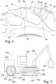
- the above-mentioned forestry machine 300 may comprise a frame 302 having two opposite sides and being wheeled for propulsion of the forestry machine.
- a pair of wheel assemblies 102 may be installed to a bogie axle assembly of the frame 302.
- At least one of the wheel assemblies 102 comprises a tyre corresponding the tyre 100 according to the examples of this description.
- the wheel assembly 102 may comprise a rim on which the tyre 100 is installed and the wheel assembly 102 is, e.g. by means of the rim, connectable to the frame 302, e.g. to a wheel mount 310 on the frame.
- the bogie axle assembly may include the wheel mount 310.
- the forestry machine 300 may have at least one track corresponding the continuous track 200, each track 200 circling a single wheel assembly 102 or a pair of wheel assemblies 102, the track being placed on the tread section 10 of the tyre 100.
- the track 200 is in contact with the primary tread blocks 20 and the elevated sections 24.
- the frame 302 of the forestry machine 300 may be articulated.
- a cabin 304 with an operator's station, an engine 306 and an articulated boom 308 may be attached to frame 302.
- a tool 400 for handling timber may be attachable to an end of the boom 308.
- the tool 400 may be e.g. a felling head or harvester head used in a harvester or a timber grapple used in a forwarder.
- the radially outermost surface 26 of the elevated section 24 offers a protecting surface adapted to protect the tread groove bottom 22 against damages caused by the track 200 to be placed on the tread section 10, see Figs. 5 and 6 .
- the shoulder surface 28 on a side of the tread section 10 offers a supporting surface adapted to support the track 200, e.g. the guide plate 204, that may contact the shoulder surface 28 which prevents lateral movement of the track 200.
- the shoulder surface 28 keeps the guide plate 204 from moving into the groove 38 and/or onto the tread section 10.
- the elevated section 24 adds material onto the tread groove bottom 22 for protecting it against damages.
- the shoulder surface 34 of the primary tread block 20 on a side of the tread section 10 offers a supporting surface adapted to support the track 200, e.g. the guide plate 204, that may contact the shoulder surface 34 which prevents lateral movement of the track 200.
- the shoulder surface 34 keeps the guide plate 204 from moving onto the tread section 10.
- the primary tread block 20 comprises in the radially outermost surface 32 one or more indentations 36 as shown in Fig. 4 .
- the indentation 36 extends in the axial direction A across the primary tread block 20.
- the indentation 36 is adapted to support the track 200 and keep the track 200 in place.
- At least one of the indentations 36 is in the axial direction A aligned with the shoulder surface 28 of the elevated section 24. That is, the indentation 36 is directed towards the shoulder surface 28.
- inclination RA of the shoulder surface 28 of the elevated section 24 in relation to the radial direction R, or the equatorial plane EQ equals or is substantially the same as inclination RB of the shoulder surface 34 of the primary tread block 20 in relation to the radial direction R, or the equatorial plane EQ.
- the shoulder surfaces 28, 34 are inclined in such a way that the farther the shoulder surfaces 28, 34 get from the centreline CL the nearer they get to the equatorial plane EQ.
- the above-mentioned inclination angle RA, RB is 0°, or at least 2°, or 5°, or at least 10°. Additionally, the above-mentioned inclination angle RA, RB may be at the most 20°, or 30°, or at the most 40°. Thus, the shoulder surfaces 28, 34 incline towards the radially outermost surfaces 26, 32.
- each shoulder surface 28, 34 of the primary tread blocks 20 and the elevated sections 24 are arranged in a circular pattern in relation to the centreline CL.
- each shoulder surface 28, 34 includes a section on which the track 200 is supported.
- the sections on the shoulder surfaces 28, 34 are at equal or substantially equal distances D1 from the axis of rotation CL, see Fig. 6 .
- the shoulder surfaces 34 of the primary tread blocks 20 and the shoulder surfaces 28 of the elevated sections 24 are in the axial direction A at equal distances D2 or at substantially equal distances D2 from the equatorial plane EP, see Fig. 6 .
- the elevated section24 is positioned correspondingly.
- the elevated section 24 between a pair of the primary tread blocks 20 is closer to one of the primary tread blocks 20 of the pair.
- the elevated section 24 is located within a distance D4 from the one primary tread block 20.
- the distance D4 is at the most 80%, or 60%, or preferably at the most 40%, of the distance D3 between the primary tread blocks 20 of the pair, the distance D3 substantially corresponding the width of the tread groove 38.
- the distances D3, D4 are measured in the circumferential direction C, preferably in the shoulder region 16 or at the shoulder surface 28.
- the forestry machine 300 may have a tyre chain 500 encircling one or more tyres 100 and being placed on the tread section 10 of the tyre 100, see Fig. 7 .
- the tyre chain 500 is in contact with the primary tread blocks 20 and the elevated sections 24.
- the shoulder surface 28 of the elevated section 24 supports the tyre chain 500 when the tyre chain 500 is placed on the tread section 10.
Landscapes
- Engineering & Computer Science (AREA)
- Mechanical Engineering (AREA)
- Chemical & Material Sciences (AREA)
- Combustion & Propulsion (AREA)
- Transportation (AREA)
- Tires In General (AREA)
Claims (14)
- Luftreifen für den Einsatz in der Forstwirtschaft, wobei der Reifen (100) Folgendes umfasst:- einen bodenberührenden Laufflächenabschnitt (10), der sich in Umfangsrichtung (C) des Reifens um diesen herum erstreckt, wobei der Laufflächenabschnitt eine imaginäre Äquatorialebene (EP) definiert, die senkrecht zu einer axialen Richtung (A) des Reifens ist und durch einen Mittelbereich (40) des Laufflächenabschnitts verläuft;- ein Paar Wulstabschnitte (12), die sich auf zwei gegenüberliegenden Seiten des Reifens befinden;- ein Paar Seitenwandabschnitte (14), die sich auf zwei gegenüberliegenden Seiten des Reifens befinden, wobei sich jeder Seitenwandabschnitt zwischen dem jeweiligen Wulstabschnitt und dem Laufflächenabschnitt erstreckt, und wobei der Laufflächenabschnitt ein Paar Schulterbereiche (16) neben dem jeweiligen Seitenwandabschnitt definiert;- wobei der Laufflächenabschnitt auf beiden Seiten der Äquatorialebene eine Laufflächenblockreihe (50) umfasst und sich jede Laufflächenblockreihe in Umfangsrichtung erstreckt;- wobei jede Laufflächenblockreihe eine Reihe von primären Laufflächenblöcken (20) umfasst, die entlang der Umfangsrichtung beabstandet sind und Laufflächenrillen (38) definieren, die sich zwischen den primären Laufflächenblöcken befinden und einen Laufflächenrillenboden (22) definieren, von dessen Niveau aus sich die primären Laufflächenblöcke radial bis zu einer Höhe (H1) erstrecken, bei der jeder primäre Laufflächenblock eine radial äußerste Oberfläche (32) umfasst;- wobei jeder primäre Laufflächenblock schräg zur Umfangsrichtung ausgerichtet ist und schräg zur Axialrichtung vom Mittelbereich zum Schulterbereich verläuft,- wobei jeder primäre Laufflächenblock (20) die radial äußerste Oberfläche (32) und eine axial äußerste Schulteroberfläche (34) umfasst, wobei die Schulteroberfläche im Schulterbereich (16) quer zur radial äußersten Oberfläche (32) ausgerichtet ist, und- wobei die radial äußerste Oberfläche (32) eine Stützfläche bereitstellt, die zum Stützen einer Raupenkette (200) geeignet ist, die auf dem Laufflächenabschnitt platziert werden kann, und die axial äußerste Schulteroberfläche (34) eine Stützfläche bereitstellt, die zum Stützen der Raupenkette geeignet ist;- wobei jede Laufflächenblockreihe (50) ferner eine Reihe von erhöhten Abschnitten (24) umfasst, wobei sich jeder erhöhte Abschnitt in der Laufflächenrille (38) zwischen zwei aufeinanderfolgenden primären Laufflächenblöcken (20) befindet, mit einem davon der erhöhte Abschnitt verbunden ist, wobei sich jeder erhöhte Abschnitt radial von der Ebene des Laufflächenrillenbodens (22) erstreckt und in der Laufflächenrille schräg in Bezug auf die axiale Richtung zum Schulterbereich verläuft;- wobei jeder erhöhte Abschnitt eine radial äußerste Oberfläche (26) aufweist, und zwar derart- dass der erhöhte Abschnitt sich radial von der Höhe des Laufflächenrillenbodens bis zu einer Höhe (H2) erstreckt, die in Bezug auf die Höhe (H1) der radial äußersten Oberflächen (26) der primären Laufflächenblöcke verringert ist; und- wobei jeder erhöhte Abschnitt außerdem eine axial äußerste Schulterfläche (28) aufweist, und zwar derart- dass die Schulterfläche (28) im Schulterbereich (16) quer zur radial äußersten Fläche (26) des erhöhten Abschnitts (24) ausgerichtet ist; und- dass die radial äußerste Oberfläche (26) des erhöhten Abschnitts (24) eine Schutzoberfläche bietet, die zum Schutz des Laufflächenrillenbodens vor der Raupenkette (200) geeignet ist, und dass die Schulteroberfläche (28) des erhöhten Abschnitts (24) eine Stützoberfläche bietet, die zum Stützen der Raupenkette geeignet ist dadurch gekennzeichnet, dass jeder erhöhte Abschnitt (24), mit dem sich jeder primäre Laufflächenblock (20) verbindet, an einer Rückwand des primären Laufflächenblocks (20) angeordnet ist, wobei eine Seitenoberfläche des primären Laufflächenblocks (20) die Rückwand bildet, und dass an einer Vorderwand des primären Laufflächenblocks (20) kein erhöhter Abschnitt (24) vorhanden ist, wobei sich die Vorderwand auf der gegenüberliegenden Seite des primären Laufflächenblocks (20) befindet.
- Reifen nach Anspruch 1, wobei sich die Laufflächenrillenböden (22) und die erhöhten Abschnitte (24) bis zum Seitenwandabschnitt (14) erstrecken und zwar derart, dass die Schulterfläche (28) jedes erhöhten Abschnitts einen integralen Teil der Oberfläche des Seitenwandabschnitts bildet.
- Reifen nach Anspruch 1 oder 2, wobei sich die Schulterfläche (28) des erhöhten Abschnitts (24) mit der Schulterfläche (34) des primären Laufflächenblocks (20) verbindet und zwar so, dass die Schulterfläche des erhöhten Abschnitts glatt bis zur Schulterfläche des primären Laufflächenblocks reicht.
- Reifen nach Anspruch 3, wobei sich die Schulterfläche (28) des erhöhten Abschnitts (24) rillenlos oder nahtlos bis zur Schulterfläche (34) des primären Laufflächenblocks (20) erstreckt.
- Reifen nach einem der Ansprüche 1 bis 4, wobei die Neigung (RB) der Schulterfläche (28) des erhöhten Abschnitts (24) in Bezug auf eine radiale Richtung (R) gleich oder im Wesentlichen gleich der Neigung (RA) der Schulterfläche (34) des primären Laufflächenblocks (20) in Bezug auf die radiale Richtung ist.
- Reifen nach einem der Ansprüche 1 bis 5,- wobei die Schulterflächen (34) der primären Laufflächenblöcke (20) und die Schulterflächen (28) der erhöhten Abschnitte (24) in einem kreisförmigen Muster angeordnet sind; und- wobei die Schulterflächen der primären Laufflächenblöcke und die Schulterflächen der erhöhten Abschnitte jeweils einen Abschnitt umfassen, der zum Tragen der Raupenkette (200) auf dem Abschnitt geeignet ist, wobei die Abschnitte in radialer Richtung in gleichen Abständen (D1) oder in im Wesentlichen gleichen Abständen von der Rotationsachse (CL) des Reifens angeordnet sind.
- Reifen nach einem der Ansprüche 1 bis 6, wobei die Schulterflächen (34) der primären Laufflächenblöcke (20) und die Schulterflächen (28) der erhöhten Abschnitte (24) in axialer Richtung gleiche Abstände (D2) oder im Wesentlichen gleiche Abstände von der Äquatorialebene (EP) aufweisen.
- Reifen nach einem der Ansprüche 1 bis 7, wobei auf einer Seite des erhöhten Abschnitts (24) der erhöhte Abschnitt durch den Laufflächenrillenboden (22) von einem der primären Laufflächenblöcke (20) getrennt ist, und wobei auf der anderen Seite des erhöhten Abschnitts der erhöhte Abschnitt mit einem anderen der primären Laufflächenblöcke verbunden ist.
- Reifen nach einem der Ansprüche 1 bis 8, wobei der erhöhte Abschnitt (24) mit dem primären Laufflächenblock (20) verbunden ist und zwar so, dass die radial äußerste Oberfläche (26) des erhöhten Abschnitts (24) sich in Richtung des primären Laufflächenblocks erstreckt und sanft nach oben gebogen ist, um eine Seitenoberfläche des primären Laufflächenblocks zu bilden.
- Reifen nach einem der Ansprüche 1 bis 9, wobei sich die radial äußerste Oberfläche (26) jedes erhöhten Abschnitts (24) allmählich dem Niveau nähert, das durch den Laufflächenrillenboden (22) neben dem erhöhten Abschnitt definiert ist, während sich der erhöhte Abschnitt in Richtung des Mittelbereichs erstreckt.
- Reifen nach einem der Ansprüche 1 bis 10, wobei sich die primären Laufflächenblöcke (20) im Mittelbereich (40) derart abwechseln, dass jeder zweite primäre Laufflächenblock ein primärer Laufflächenblock einer der Laufflächenblockreihen (50) und jeder zweite primäre Laufflächenblock ein primärer Laufflächenblock der anderen der Laufflächenblockreihen ist.
- Forstmaschine, die einen Rahmen umfasst, wobei der Rahmen zwei gegenüberliegende Seiten aufweist und mit Rädern zum Antrieb der Forstmaschine ausgestattet ist und zwei oder mehr Radanordnungen mit Reifen auf jeder der beiden gegenüberliegenden Seiten des Rahmens aufweist, wobei mindestens eine der Radanordnungen Folgendes umfasst- einen Reifen (100) gemäß einem der Ansprüche 1 bis 11,- wobei die Forstmaschine ferner eine durchgehende Raupenkette (200) umfasst, die eine der Radanordnungen einschließlich des Reifens und/oder ein Paar von Radanordnungen einschließlich des Reifens umkreist und auf dem Laufflächenabschnitt (10) des Reifens platziert ist, wobei die Raupenkette in Kontakt mit den primären Laufflächenblöcken (20) und mit den erhöhten Abschnitten (24) ist.
- Verfahren zum Anbringen von Reifen an einer Forstmaschine mit einem Rahmen, wobei der Rahmen zwei gegenüberliegende Seiten aufweist und mit Rädern zum Antrieb der Forstmaschine ausgestattet ist und zwei oder mehr Radanordnungen mit Reifen auf jeder der beiden gegenüberliegenden Seiten des Rahmens aufweist, wobei das Verfahren durch Folgendes gekennzeichnet ist- Anbringen von mindestens einer der Radanordnungen, die einen Reifen (100) gemäß einem der Ansprüche 1 bis 11 umfasst, an dem Rahmen der Forstmaschine.
- Verfahren nach Anspruch 13, wobei das Verfahren ferner Folgendes umfasst- Installieren einer durchgehenden Raupenkette (200), die eine der Radanordnungen einschließlich des Reifens und/oder ein Paar von Radanordnungen einschließlich des Reifens umkreist und auf dem Laufflächenabschnitt (10) des Reifens platziert wird, wobei die Raupenkette in Kontakt mit den primären Laufflächenblöcken (20) und mit den erhöhten Abschnitten (24) ist.
Priority Applications (1)
| Application Number | Priority Date | Filing Date | Title |
|---|---|---|---|
| EP22178788.0A EP4082877B1 (de) | 2020-06-18 | 2020-06-18 | Fahrzeugluftreifen für die forstwirtschaft |
Applications Claiming Priority (2)
| Application Number | Priority Date | Filing Date | Title |
|---|---|---|---|
| EP20397509.9A EP3925867B1 (de) | 2020-06-18 | 2020-06-18 | Fahrzeugluftreifen für die forstwirtschaft |
| EP22178788.0A EP4082877B1 (de) | 2020-06-18 | 2020-06-18 | Fahrzeugluftreifen für die forstwirtschaft |
Related Parent Applications (2)
| Application Number | Title | Priority Date | Filing Date |
|---|---|---|---|
| EP20397509.9A Division EP3925867B1 (de) | 2020-06-18 | 2020-06-18 | Fahrzeugluftreifen für die forstwirtschaft |
| EP20397509.9A Division-Into EP3925867B1 (de) | 2020-06-18 | 2020-06-18 | Fahrzeugluftreifen für die forstwirtschaft |
Publications (3)
| Publication Number | Publication Date |
|---|---|
| EP4082877A1 EP4082877A1 (de) | 2022-11-02 |
| EP4082877C0 EP4082877C0 (de) | 2024-08-07 |
| EP4082877B1 true EP4082877B1 (de) | 2024-08-07 |
Family
ID=71661801
Family Applications (2)
| Application Number | Title | Priority Date | Filing Date |
|---|---|---|---|
| EP22178788.0A Active EP4082877B1 (de) | 2020-06-18 | 2020-06-18 | Fahrzeugluftreifen für die forstwirtschaft |
| EP20397509.9A Active EP3925867B1 (de) | 2020-06-18 | 2020-06-18 | Fahrzeugluftreifen für die forstwirtschaft |
Family Applications After (1)
| Application Number | Title | Priority Date | Filing Date |
|---|---|---|---|
| EP20397509.9A Active EP3925867B1 (de) | 2020-06-18 | 2020-06-18 | Fahrzeugluftreifen für die forstwirtschaft |
Country Status (1)
| Country | Link |
|---|---|
| EP (2) | EP4082877B1 (de) |
Families Citing this family (1)
| Publication number | Priority date | Publication date | Assignee | Title |
|---|---|---|---|---|
| EP4470795B1 (de) | 2023-05-29 | 2026-01-28 | Nokian Raskaat Renkaat Oy | Luftreifen aus gummimaterial für forstfahrzeuge |
Family Cites Families (7)
| Publication number | Priority date | Publication date | Assignee | Title |
|---|---|---|---|---|
| JPH06320915A (ja) * | 1993-05-18 | 1994-11-22 | Ohtsu Tire & Rubber Co Ltd :The | 農用タイヤ |
| EP2531362B1 (de) * | 2010-02-05 | 2015-04-08 | Pirelli Tyre S.p.A. | Landwirtschaftsreifen |
| JP5675895B2 (ja) * | 2013-05-28 | 2015-02-25 | 株式会社ブリヂストン | 農業車両用空気入りラジアルタイヤ |
| ITRM20130447A1 (it) * | 2013-07-30 | 2015-01-31 | Trelleborg Wheel Sys Italia Spa | Pneumatico con migliorate capacita' di trazione. |
| EP3412475B1 (de) | 2017-06-08 | 2019-08-21 | Nokian Raskaat Renkaat Oy | Fahrzeugluftreifen |
| CA3075960A1 (en) | 2017-07-21 | 2019-01-24 | Fomatec Oy | Track assemblies for terrain going vehicles and method for repairing the tracks |
| EP3738791B1 (de) * | 2019-05-14 | 2021-04-07 | Nokian Raskaat Renkaat Oy | Fahrzeugluftreifen für die forstwirtschaft |
-
2020
- 2020-06-18 EP EP22178788.0A patent/EP4082877B1/de active Active
- 2020-06-18 EP EP20397509.9A patent/EP3925867B1/de active Active
Also Published As
| Publication number | Publication date |
|---|---|
| EP3925867A1 (de) | 2021-12-22 |
| EP4082877C0 (de) | 2024-08-07 |
| EP4082877A1 (de) | 2022-11-02 |
| EP3925867B1 (de) | 2022-07-27 |
Similar Documents
| Publication | Publication Date | Title |
|---|---|---|
| EP3738791B1 (de) | Fahrzeugluftreifen für die forstwirtschaft | |
| US7980282B2 (en) | Tire system for an off-highway machine | |
| EP0510465B1 (de) | Luftreifen für die Landwirtschaft oder die Holzbringung | |
| US7640996B2 (en) | Walking beam and tire system for an earthmoving scraping device | |
| US10745068B2 (en) | Endless track and guide member | |
| US6299181B1 (en) | Vehicle having steerable wheels | |
| EP4082877B1 (de) | Fahrzeugluftreifen für die forstwirtschaft | |
| FI126750B (fi) | Metsäkone ja telayksikkö | |
| EP0194069A2 (de) | Fahrzeugrad und radialer Luftreifen | |
| US4445582A (en) | Track unit of bogie type | |
| US20040118497A1 (en) | Pneumatic tire for use on row-crop field sprayers and other like farm machinery | |
| CA3091545A1 (en) | Track assembly for terrain going vehicles and a link for the track assembly | |
| US11753092B2 (en) | Interchangeable track systems | |
| US20100300589A1 (en) | Wheel having a segmented tire | |
| EP2920005B1 (de) | Radanordnung und fahrzeug damit | |
| EP4470795B1 (de) | Luftreifen aus gummimaterial für forstfahrzeuge | |
| CA2129022C (en) | Chassis for a utility vehicle | |
| BR112013015582B1 (pt) | pneumático | |
| FI130425B (en) | Band plate and band set | |
| US11427041B2 (en) | Chain system for a continuous track | |
| US20040123926A1 (en) | Off road tire having variable width puncture preventing pads | |
| US5152583A (en) | Continuous-operation extraction machinery for strip mining with a cylindrical extractor | |
| EP3202253B1 (de) | Zuführmittel und rundholzverarbeitungskopf | |
| US20230061578A1 (en) | Vehicle Platforms | |
| AU2003100410A4 (en) | Track and Guide System for a Skid-Steer Vehicle |
Legal Events
| Date | Code | Title | Description |
|---|---|---|---|
| PUAI | Public reference made under article 153(3) epc to a published international application that has entered the european phase |
Free format text: ORIGINAL CODE: 0009012 |
|
| STAA | Information on the status of an ep patent application or granted ep patent |
Free format text: STATUS: THE APPLICATION HAS BEEN PUBLISHED |
|
| AC | Divisional application: reference to earlier application |
Ref document number: 3925867 Country of ref document: EP Kind code of ref document: P |
|
| AK | Designated contracting states |
Kind code of ref document: A1 Designated state(s): AL AT BE BG CH CY CZ DE DK EE ES FI FR GB GR HR HU IE IS IT LI LT LU LV MC MK MT NL NO PL PT RO RS SE SI SK SM TR |
|
| STAA | Information on the status of an ep patent application or granted ep patent |
Free format text: STATUS: REQUEST FOR EXAMINATION WAS MADE |
|
| 17P | Request for examination filed |
Effective date: 20230301 |
|
| RBV | Designated contracting states (corrected) |
Designated state(s): AL AT BE BG CH CY CZ DE DK EE ES FI FR GB GR HR HU IE IS IT LI LT LU LV MC MK MT NL NO PL PT RO RS SE SI SK SM TR |
|
| GRAP | Despatch of communication of intention to grant a patent |
Free format text: ORIGINAL CODE: EPIDOSNIGR1 |
|
| STAA | Information on the status of an ep patent application or granted ep patent |
Free format text: STATUS: GRANT OF PATENT IS INTENDED |
|
| INTG | Intention to grant announced |
Effective date: 20240516 |
|
| GRAS | Grant fee paid |
Free format text: ORIGINAL CODE: EPIDOSNIGR3 |
|
| GRAA | (expected) grant |
Free format text: ORIGINAL CODE: 0009210 |
|
| STAA | Information on the status of an ep patent application or granted ep patent |
Free format text: STATUS: THE PATENT HAS BEEN GRANTED |
|
| AC | Divisional application: reference to earlier application |
Ref document number: 3925867 Country of ref document: EP Kind code of ref document: P |
|
| AK | Designated contracting states |
Kind code of ref document: B1 Designated state(s): AL AT BE BG CH CY CZ DE DK EE ES FI FR GB GR HR HU IE IS IT LI LT LU LV MC MK MT NL NO PL PT RO RS SE SI SK SM TR |
|
| REG | Reference to a national code |
Ref country code: GB Ref legal event code: FG4D |
|
| REG | Reference to a national code |
Ref country code: CH Ref legal event code: EP |
|
| REG | Reference to a national code |
Ref country code: IE Ref legal event code: FG4D |
|
| REG | Reference to a national code |
Ref country code: DE Ref legal event code: R096 Ref document number: 602020035582 Country of ref document: DE |
|
| U01 | Request for unitary effect filed |
Effective date: 20240906 |
|
| U07 | Unitary effect registered |
Designated state(s): AT BE BG DE DK EE FI FR IT LT LU LV MT NL PT RO SE SI Effective date: 20240923 |
|
| PG25 | Lapsed in a contracting state [announced via postgrant information from national office to epo] |
Ref country code: NO Free format text: LAPSE BECAUSE OF FAILURE TO SUBMIT A TRANSLATION OF THE DESCRIPTION OR TO PAY THE FEE WITHIN THE PRESCRIBED TIME-LIMIT Effective date: 20241107 |
|
| PG25 | Lapsed in a contracting state [announced via postgrant information from national office to epo] |
Ref country code: PL Free format text: LAPSE BECAUSE OF FAILURE TO SUBMIT A TRANSLATION OF THE DESCRIPTION OR TO PAY THE FEE WITHIN THE PRESCRIBED TIME-LIMIT Effective date: 20240807 Ref country code: GR Free format text: LAPSE BECAUSE OF FAILURE TO SUBMIT A TRANSLATION OF THE DESCRIPTION OR TO PAY THE FEE WITHIN THE PRESCRIBED TIME-LIMIT Effective date: 20241108 |
|
| PG25 | Lapsed in a contracting state [announced via postgrant information from national office to epo] |
Ref country code: IS Free format text: LAPSE BECAUSE OF FAILURE TO SUBMIT A TRANSLATION OF THE DESCRIPTION OR TO PAY THE FEE WITHIN THE PRESCRIBED TIME-LIMIT Effective date: 20241207 |
|
| PG25 | Lapsed in a contracting state [announced via postgrant information from national office to epo] |
Ref country code: HR Free format text: LAPSE BECAUSE OF FAILURE TO SUBMIT A TRANSLATION OF THE DESCRIPTION OR TO PAY THE FEE WITHIN THE PRESCRIBED TIME-LIMIT Effective date: 20240807 |
|
| PG25 | Lapsed in a contracting state [announced via postgrant information from national office to epo] |
Ref country code: ES Free format text: LAPSE BECAUSE OF FAILURE TO SUBMIT A TRANSLATION OF THE DESCRIPTION OR TO PAY THE FEE WITHIN THE PRESCRIBED TIME-LIMIT Effective date: 20240807 Ref country code: RS Free format text: LAPSE BECAUSE OF FAILURE TO SUBMIT A TRANSLATION OF THE DESCRIPTION OR TO PAY THE FEE WITHIN THE PRESCRIBED TIME-LIMIT Effective date: 20241107 |
|
| PG25 | Lapsed in a contracting state [announced via postgrant information from national office to epo] |
Ref country code: RS Free format text: LAPSE BECAUSE OF FAILURE TO SUBMIT A TRANSLATION OF THE DESCRIPTION OR TO PAY THE FEE WITHIN THE PRESCRIBED TIME-LIMIT Effective date: 20241107 Ref country code: PL Free format text: LAPSE BECAUSE OF FAILURE TO SUBMIT A TRANSLATION OF THE DESCRIPTION OR TO PAY THE FEE WITHIN THE PRESCRIBED TIME-LIMIT Effective date: 20240807 Ref country code: NO Free format text: LAPSE BECAUSE OF FAILURE TO SUBMIT A TRANSLATION OF THE DESCRIPTION OR TO PAY THE FEE WITHIN THE PRESCRIBED TIME-LIMIT Effective date: 20241107 Ref country code: IS Free format text: LAPSE BECAUSE OF FAILURE TO SUBMIT A TRANSLATION OF THE DESCRIPTION OR TO PAY THE FEE WITHIN THE PRESCRIBED TIME-LIMIT Effective date: 20241207 Ref country code: HR Free format text: LAPSE BECAUSE OF FAILURE TO SUBMIT A TRANSLATION OF THE DESCRIPTION OR TO PAY THE FEE WITHIN THE PRESCRIBED TIME-LIMIT Effective date: 20240807 Ref country code: GR Free format text: LAPSE BECAUSE OF FAILURE TO SUBMIT A TRANSLATION OF THE DESCRIPTION OR TO PAY THE FEE WITHIN THE PRESCRIBED TIME-LIMIT Effective date: 20241108 Ref country code: ES Free format text: LAPSE BECAUSE OF FAILURE TO SUBMIT A TRANSLATION OF THE DESCRIPTION OR TO PAY THE FEE WITHIN THE PRESCRIBED TIME-LIMIT Effective date: 20240807 |
|
| PG25 | Lapsed in a contracting state [announced via postgrant information from national office to epo] |
Ref country code: SM Free format text: LAPSE BECAUSE OF FAILURE TO SUBMIT A TRANSLATION OF THE DESCRIPTION OR TO PAY THE FEE WITHIN THE PRESCRIBED TIME-LIMIT Effective date: 20240807 |
|
| PG25 | Lapsed in a contracting state [announced via postgrant information from national office to epo] |
Ref country code: CZ Free format text: LAPSE BECAUSE OF FAILURE TO SUBMIT A TRANSLATION OF THE DESCRIPTION OR TO PAY THE FEE WITHIN THE PRESCRIBED TIME-LIMIT Effective date: 20240807 |
|
| PG25 | Lapsed in a contracting state [announced via postgrant information from national office to epo] |
Ref country code: SK Free format text: LAPSE BECAUSE OF FAILURE TO SUBMIT A TRANSLATION OF THE DESCRIPTION OR TO PAY THE FEE WITHIN THE PRESCRIBED TIME-LIMIT Effective date: 20240807 |
|
| PLBE | No opposition filed within time limit |
Free format text: ORIGINAL CODE: 0009261 |
|
| STAA | Information on the status of an ep patent application or granted ep patent |
Free format text: STATUS: NO OPPOSITION FILED WITHIN TIME LIMIT |
|
| 26N | No opposition filed |
Effective date: 20250508 |
|
| U20 | Renewal fee for the european patent with unitary effect paid |
Year of fee payment: 6 Effective date: 20250617 |
|
| REG | Reference to a national code |
Ref country code: CH Ref legal event code: H13 Free format text: ST27 STATUS EVENT CODE: U-0-0-H10-H13 (AS PROVIDED BY THE NATIONAL OFFICE) Effective date: 20260127 |
|
| PG25 | Lapsed in a contracting state [announced via postgrant information from national office to epo] |
Ref country code: MC Free format text: LAPSE BECAUSE OF FAILURE TO SUBMIT A TRANSLATION OF THE DESCRIPTION OR TO PAY THE FEE WITHIN THE PRESCRIBED TIME-LIMIT Effective date: 20240807 |
|
| GBPC | Gb: european patent ceased through non-payment of renewal fee |
Effective date: 20250618 |