EP2920005B1 - Radanordnung und fahrzeug damit - Google Patents
Radanordnung und fahrzeug damit Download PDFInfo
- Publication number
- EP2920005B1 EP2920005B1 EP13854414.3A EP13854414A EP2920005B1 EP 2920005 B1 EP2920005 B1 EP 2920005B1 EP 13854414 A EP13854414 A EP 13854414A EP 2920005 B1 EP2920005 B1 EP 2920005B1
- Authority
- EP
- European Patent Office
- Prior art keywords
- rotation
- axis
- central hub
- wheel assembly
- alternating
- Prior art date
- Legal status (The legal status is an assumption and is not a legal conclusion. Google has not performed a legal analysis and makes no representation as to the accuracy of the status listed.)
- Active
Links
Images


Classifications
-
- B—PERFORMING OPERATIONS; TRANSPORTING
- B60—VEHICLES IN GENERAL
- B60B—VEHICLE WHEELS; CASTORS; AXLES FOR WHEELS OR CASTORS; INCREASING WHEEL ADHESION
- B60B3/00—Disc wheels, i.e. wheels with load-supporting disc body
- B60B3/002—Disc wheels, i.e. wheels with load-supporting disc body characterised by the shape of the disc
-
- B—PERFORMING OPERATIONS; TRANSPORTING
- B60—VEHICLES IN GENERAL
- B60B—VEHICLE WHEELS; CASTORS; AXLES FOR WHEELS OR CASTORS; INCREASING WHEEL ADHESION
- B60B21/00—Rims
-
- B—PERFORMING OPERATIONS; TRANSPORTING
- B60—VEHICLES IN GENERAL
- B60B—VEHICLE WHEELS; CASTORS; AXLES FOR WHEELS OR CASTORS; INCREASING WHEEL ADHESION
- B60B25/00—Rims built-up of several main parts ; Locking means for the rim parts
- B60B25/02—Segmented rims, e.g. with segments arranged in sections; Connecting equipment, e.g. hinges; Insertable flange rings therefor
Definitions
- the present invention relates generally to wheels and, more particularly, to wheels configured to be used on a variety of terrains and surfaces.
- a wheel in the simplest terms, is a circular component that rotates on an axle.
- the main advantage of a wheel is that it greatly reduces friction by rolling across a flat surface compared to sliding or dragging an object.
- Early wheels were simple wooden disks with a hole for an axle.
- a cross section of a tree was used.
- this type of wheel was problematic because it did not have sufficient structural strength to support weight without breaking. It was inherently flawed because a cross section of a tree does not utilize the strength of the grain of wood, like a plank cut lengthwise.
- three lengthwise cut planks were banded together side by side, with the axle hole bored through the centerpiece, and shaped into a circle.
- the invention is defined in its broadest terms in claims 1, 6 and 12 below, and provides a wheel assembly having a body formed as an alternating pattern circumscribed about a central hub.
- the body has a constant radial distance from the axis of rotation, as referenced by a median circle centered on the axis of rotation and defined by the body's alternating pattern.
- the wheel can be adapted for use in any type of vehicle for transportation, such as a car, bicycle, skateboard, and wheelchair, among others.
- the wheel body defines an effective width (We) greater than a body width (Wb).
- We effective width
- Wb body width
- the wheel assembly can provide a broad track while maintaining a relatively thin contact area in that the wheel assembly generates less friction than a traditional wheel with a comparable effective width.
- soft surfaces e.g., sand
- the broad travel path of the wheel assembly enables the vehicle to travel smoothly without unduly sinking into soft material, providing substantial traction, particularly if the wheel begins to slip.
- the wheel body is formed of a plurality of arcs connected in sequential, adjacent alignment to circumscribe the central hub.
- Each arc having an arc center that is spaced apart from the axis of rotation, such that adjacent arcs have arc center on opposing sides of the body.
- each arc of the plurality of arcs has an arc angle of 90 degrees, in which the alternating pattern is formed of six arcs.
- each wheel 42 includes a hub 14 and an annular body 12 having an alternating pattern circumscribed about hub 14.
- Wheels 42 each include a plurality of spokes 20 connecting to hub 14 and projecting relative wheels 42. The outermost ends of spokes 20 attach along an inner edge of body 12.
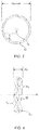
- the bicycle may include a front fork 22 sized to accommodate an effective width ( W e ) of body 12 as shown in FIG. 4 .
- W e effective width
- wheel 42 provides a broad track, the effective width ( W e ), while maintaining a relatively thin contact area with a surface upon which bicycle 21 may ride and this results in less friction than a traditional wheel with a comparable effective width.
- the effective width ( W e ) of wheel 42 enables bicycle 21 to travel smoothly without undue sinking into the soft material (see, FIGS. 5-7 ), while providing substantial traction, for example, in scenarios in which wheel 42 begins to slip, the wheel's contact area with the soft surface increases up to the effective width ( W e ), providing additional traction.
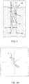
- FIG. 7 depicts wheel 42 from a front view.
- the alternating arc portions of wheel 42 produces the alternating pattern on its rolling surface, as shown in FIG. 6 .
- wheel 42 has effective width (We) but has less contact surface area (Wt), and therefore less fluid dynamic drag, as compared with a conventional wheel of similar width.
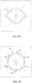
- body 12 is coupled to hub 14, and rotates about an axis of rotation ( A r ) at a constant radial distance ( R d ) from the axis of rotation A r .
- the body 12 defines a median circle ( C m ) centered on the plane of rotation and is transverse to the axis of rotation ( A r ).
- the alternating pattern of body 12 is evenly distributed across the median circle.
- the alternating pattern is a series of alternating curved portions disposed on opposing sides of the median circle ( C m ), forming a wave pattern having a constant amplitude and a constant frequency.
- body 12 may include six alternating portions in sequential alignment which extend on alternating sides of median circle ( C m ) see Fig. 4 .
- Each portion is shaped as an arc having an arc angle that may comprise 90 degrees as shown in the exemplary embodiment in FIG. 8E , where arc portions that are located diametrically opposite on body 12 are in mutually parallel orientation to one another, e.g. opposing arc portions: 12a & 12d, 12b & 12e, and 12c & 12f)
- the amplitude and frequency of the portions can vary across embodiments as well as within.
- the shape of body 12 can vary in other embodiments.
- the number and shapes of the alternating portions can vary.
- wheel 42 is depicted as having a plurality of arc portions disposed in an alternating arrangement about hub 14.
- wheel 42 is depicted as having a greater number of arc portions disposed in an alternating arrangement about hub 14.
- the amplitude and frequency of the portions can vary across embodiments as well as within an embodiment.
- the alternating portions need not be limited to a curved shape. Any other shape can be used such as squared, pie, or cantilevered portions, among others.
- one or more portions of body 12 can extend around median circle ( C m ) at prescribed location(s), interspaced between alternating portions.
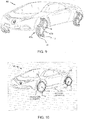
- a motor vehicle 40 may have four dual wheel sets, as shown. Each wheel set may have a pair of wheels 42 mounted in side-by-side alignment.
- the bodies 12 may incorporate the alternating pattern discussed above.
- the bodies 12 can share a hub 14, or the bodies 12 can each have a separate hub 14.
- an inner wheel 42a and an outer wheel 42b need not have the same shape or configuration alignment.
- an amphibious vehicle 50 may include four dual wheels sets as shown, each with a pair of bodies 12 mounted in alignment with each other.
- the bodies 12 may incorporate the alternating pattern discussed above.
- the bodies 12 can share a hub 14 or each can be mounted to a separate hub 14.
- Bodies 12 may have a shape that provides propulsion when the vehicle is in water.
- the vehicle 50 may include an inflatable underbelly support 52 mounted to the vehicle's undercarriage.
- the support 52 may be configured and sized to aid in floatation of vehicle 50.
- wheel 42 may include a hub 14, a rim 7, and a tire 8.
- Rim 7 and tire 8 cooperatively may define the alternating pattern as discussed above.
- Body 12 can accommodate pneumatic tires or other types.
- body 12 may provide rim 7 supporting a pneumatic tire and inner tube.
- body 12 may be designed for tubular tires, which attach to rim 7 by adhesive or other approaches known in the art.
- the body 12 can be formed of other variations of tires and rim configurations known in the art and can be used without departing from the scope of the invention as herein described and illustrated.
- three skateboard wheels 60, 62 and 64 are disposed in alignment with each other. These wheels incorporate an alternating pattern, as discussed above.
- the bodies 12 can share a hub, or each can have a separate hub.
- the wheels 60, 62, 64 are positioned to be mounted adjacent to each other on an axle of a skateboard truck. In other embodiments incorporating dual wheel configurations, an inner wheel and an outer wheel need not have the same shape or alignment.
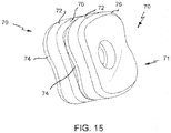
- the wheels 70 may be formed of layers of materials, in which the layers are disposed in alignment about an axis of rotation. In an exemplary embodiment, the layers may be aligned with sidewalls 71 of whee 70.
- the layers may incorporate materials having different material parameters, such as, elasticity, stiffness, pliability, hardness (durometer), among others.
- the wheel 70 may include a center layer 72 that is comparatively softer than adjacent layers 74, 76.
Landscapes
- Engineering & Computer Science (AREA)
- Mechanical Engineering (AREA)
- Tires In General (AREA)
- Pulleys (AREA)
Claims (13)
- Fahrzeugradanordnung, Folgendes umfassend:eine zentrale Nabe (14), die die Drehachse definiert; undeinen Körper (12), der mit der zentralen Nabe (14) gekoppelt ist, um sich um die Drehachse zu drehen, wobei der Körper ein um die zentrale Nabe herum umschriebenes, alternierendes Muster ausbildet, wobei der Körper (12) einen konstanten radialen Abstand von der Drehachse aufweist und einen auf der Drehachse (Ar) zentrierten und quer dazu angeordneten Mittelkreis (Cm) definiert, dadurch gekennzeichnet, dass das alternierende Muster eine Reihe von alternierenden gekrümmten Abschnitten ist, die auf einander gegenüberliegenden Seiten des Mittelkreises (Cm) angeordnet sind, um, bezogen auf den Mittelkreis (Cm), ein Wellenmuster mit einer konstanten Amplitude und einer konstanten Frequenz zu definieren.
- Fahrzeugradanordnung (50) nach Anspruch 1, wobei der Körper (12) aus mehreren Bögen, die in sequenzieller, benachbarter Ausrichtung verbunden sind, ausgebildet ist, um die zentrale Nabe (12) zu umschreiben, wobei jeder Bogen eine Bogenmitte aufweist, die so von der Drehachse (Ar) beabstandet ist, dass benachbarte Bögen auf gegenüberliegenden Seiten des Körpers eine Bogenmitte aufweisen.
- Fahrzeugradanordnung nach Anspruch 1, wobei der Körper (12) ein effektives Verhältnis von Breite (We) zu Durchmesser von mindestens 0,2 aufweist.
- Fahrzeugradanordnung nach Anspruch 1, wobei der Körper (12) eine größere effektive Breite (We) als eine Körperbreite (Wb) definiert.
- Fahrzeugradanordnung nach Anspruch 1, ferner einen zweiten Körper (12) umfassend, der an der zentralen Nabe angrenzend an den ersten Körper (12) gekoppelt ist, wobei der zweite Körper (12) befestigt ist, um sich um die Drehachse zu drehen, wobei der zweite Körper (12) ein alternierendes Muster auf einander gegenüberliegenden Seiten des Mittelkreises (Cm) ausbildet, wobei das alternierende Muster des zweiten Körpers einen um die zentrale Nabe (12) in einem konstanten radialen Abstand von der Drehachse zentrierten Mittelkreis (Cm) definiert und sowohl in axialer als auch in Umfangsrichtung kontinuierlich gekrümmt ist.
- Fahrzeugradanordnung, Folgendes umfassend:eine zentrale Nabe (14), die die Drehachse definiert; undeinen Körper (12), der mit der zentralen Nabe (14) gekoppelt ist, um sich um die Drehachse zu drehen, wobei der Körper (12) mehrere alternierend gekrümmte Abschnitte aufweist, die in sequenzieller, benachbarter Ausrichtung verbunden sind, um die zentrale Nabe (14) zu umschreiben, wobei jeder alternierend gekrümmte Abschnitt einen Bogenmittelpunkt aufweist, der von der Drehachse (Ar) beabstandet ist, und einen auf der Drehachse (Ar) zentrierten und quer dazu verlaufenden Mittelkreis (Cm) definiert, so dass benachbarte, alternierend gekrümmte Abschnitte Bogenmittelpunkte auf gegenüberliegenden Seiten des Körpers (12) aufweisen, dadurch gekennzeichnet, dass die benachbarten Bögen ein alternierendes Muster ausbilden, das auf einander gegenüberliegenden Seiten des Mittelkreises (Cm) angeordnet ist, um ein Wellenmuster mit einer konstanten Amplitude und einer konstanten Frequenz relativ zum Mittelkreis (Cm) zu definieren.
- Fahrzeugradanordnung nach Anspruch 6, wobei der Körper (12) eine effektive Breite (We) definiert, die größer ist als eine Körperbreite (Wb).
- Fahrzeugradanordnung nach Anspruch 6, wobei jeder Bogen der mehreren Bögen einen Bogenwinkel von 90 Grad aufweist.
- Fahrzeugradanordnung nach Anspruch 8, wobei die mehreren Bögen aus sechs Bögen bestehen.
- Fahrzeugradanordnung nach Anspruch 6, wobei die mehreren Bögen mehr als sechs Bögen enthalten.
- Fahrzeugradanordnung nach Anspruch 6, ferner einen zweiten Körper (12) umfassend, der an der zentralen Nabe (14) angrenzend an den ersten Körper (12) gekoppelt ist, wobei der zweite Körper (12) befestigt ist, um sich um die Drehachse zu drehen, wobei der zweite Körper (12) ein alternierendes Muster auf einander gegenüberliegenden Seiten des Mittelkreises (Cm) ausbildet, um ein Wellenmuster mit einer konstanten Amplitude und einer konstanten Frequenz relativ zum Mittelkreis (Cm) zu definieren.
- Fahrzeugradanordnung (50), Folgendes umfassend:eine zentrale Nabe (52), die die Drehachse definiert; undeinen Körper, der Folgendes enthält: eine Felge (54), gekoppelt mit der zentralen Nabe (52), und einen Reifen (56), der an der Felge (54) montiert ist, um sich um die Drehachse (Ar) zu drehen, wobei der Körper ein alternierendes Muster ausbildet, das um die zentrale Nabe (52) umschrieben ist, wobei das alternierende Muster des Körpers einen Mittelkreis (Cm) definiert, der um die zentrale Nabe (52) in einem konstanten radialen Abstand von der Drehachse (Ar) zentriert ist, dadurch gekennzeichnet, dass das alternierende Muster eine Reihe alternierender gekrümmter Abschnitte ist, die auf einander gegenüberliegenden Seiten des Mittelkreises (Cm) angeordnet sind, um ein alternierendes Muster mit einer konstanten Amplitude und einer konstanten Frequenz relativ zum Mittelkreis (Cm) zu definieren.
- Fahrzeugradanordnung (50) nach Anspruch 12, wobei das alternierende Muster aus mehreren Bögen besteht, die in sequenzieller, benachbarter Ausrichtung verbunden sind und die zentrale Nabe (52) umschreiben, wobei jeder Bogen eine Bogenmitte aufweist, die so von der Drehachse beabstandet ist, dass benachbarte Bögen auf gegenüberliegenden Seiten des Körpers eine Bogenmitte aufweisen.
Priority Applications (1)
| Application Number | Priority Date | Filing Date | Title |
|---|---|---|---|
| PL13854414T PL2920005T3 (pl) | 2012-11-14 | 2013-05-08 | Zespół koła i zawierający go pojazd |
Applications Claiming Priority (2)
| Application Number | Priority Date | Filing Date | Title |
|---|---|---|---|
| US13/676,790 US20140132059A1 (en) | 2012-11-14 | 2012-11-14 | Wheel assembly and vehicle incorporating same |
| PCT/US2013/040213 WO2014077894A1 (en) | 2012-11-14 | 2013-05-08 | Wheel assembly and vehicle incorporating same |
Publications (3)
| Publication Number | Publication Date |
|---|---|
| EP2920005A1 EP2920005A1 (de) | 2015-09-23 |
| EP2920005A4 EP2920005A4 (de) | 2017-02-22 |
| EP2920005B1 true EP2920005B1 (de) | 2019-07-17 |
Family
ID=50681015
Family Applications (1)
| Application Number | Title | Priority Date | Filing Date |
|---|---|---|---|
| EP13854414.3A Active EP2920005B1 (de) | 2012-11-14 | 2013-05-08 | Radanordnung und fahrzeug damit |
Country Status (10)
| Country | Link |
|---|---|
| US (1) | US20140132059A1 (de) |
| EP (1) | EP2920005B1 (de) |
| CN (1) | CN105121177B (de) |
| AU (1) | AU2013345403A1 (de) |
| BR (1) | BR112015010933A2 (de) |
| CA (1) | CA2891411A1 (de) |
| DK (1) | DK2920005T3 (de) |
| ES (1) | ES2751412T3 (de) |
| PL (1) | PL2920005T3 (de) |
| WO (1) | WO2014077894A1 (de) |
Families Citing this family (4)
| Publication number | Priority date | Publication date | Assignee | Title |
|---|---|---|---|---|
| US10899172B2 (en) | 2012-11-14 | 2021-01-26 | Shark Wheel, Inc. | Sinusoidal wheel |
| US10974919B2 (en) | 2012-11-14 | 2021-04-13 | Shark Wheel, Inc. | Device and method for aligning material sheets |
| US10118439B1 (en) * | 2015-11-27 | 2018-11-06 | Shark Wheel, LLC | Wheel having a sinusoidal circumference |
| USD898324S1 (en) | 2018-08-30 | 2020-10-06 | Shark Wheel, Inc. | Pallet truck wheels |
Family Cites Families (19)
| Publication number | Priority date | Publication date | Assignee | Title |
|---|---|---|---|---|
| US907991A (en) * | 1907-11-01 | 1908-12-29 | Joseph O Dye | Traction-wheel. |
| US1081844A (en) * | 1913-09-13 | 1913-12-16 | William A Kimmel | Spring-wheel. |
| US1395734A (en) * | 1920-12-20 | 1921-11-01 | Globe Machine & Stamping Co | Wheel |
| US1453542A (en) * | 1921-12-07 | 1923-05-01 | Beisel William Jakob | Spring wheel |
| US1779994A (en) * | 1926-09-03 | 1930-10-28 | John W Tatter | Tractor wheel |
| US3064796A (en) * | 1959-03-05 | 1962-11-20 | Fisher & Ludlow Ltd | Pulleys, rollers and other wheel-like members |
| SU384697A1 (ru) * | 1966-06-06 | 1973-05-29 | Автомобиль-амфибия | |
| US3913981A (en) * | 1974-06-06 | 1975-10-21 | Solis Dennis A | Dual tire wheel and method of making same |
| JPS58191603A (ja) * | 1982-04-30 | 1983-11-08 | Honda Motor Co Ltd | 車両用ホイ−ル |
| US4674757A (en) * | 1985-06-24 | 1987-06-23 | Martin William B | Stair-climbing wheel utilizing an involute curve configuration |
| US7174935B2 (en) * | 2002-11-05 | 2007-02-13 | Soleyman Kahen | Automatic safety tire device |
| US20050116539A1 (en) * | 2003-12-01 | 2005-06-02 | Jiazheng Lu | Walking wheel for bicycle |
| CN101085594A (zh) * | 2006-06-06 | 2007-12-12 | 李天夫 | 水陆两用滚筒车 |
| SE530394C2 (sv) * | 2006-10-04 | 2008-05-20 | Sesyk Ab | Stötdämpande hjul |
| US7946658B2 (en) * | 2008-12-16 | 2011-05-24 | Rph Irrigation Services Ltd. | Wheel hub, system and method for rut reduction in self propelled irrigation systems |
| RU2414360C1 (ru) * | 2009-10-19 | 2011-03-20 | Юлия Алексеевна Щепочкина | Колесо |
| US8002294B2 (en) * | 2009-12-10 | 2011-08-23 | Disney Enterprises, Inc. | Vehicle wheel assembly with a mechanism compensating for a varying wheel radius |
| US8905490B2 (en) * | 2010-03-29 | 2014-12-09 | Robosynthesis Limited | Wheel and wheel assembly |
| RU2438879C1 (ru) * | 2010-11-09 | 2012-01-10 | Юлия Алексеевна Щепочкина | Колесо |
-
2012
- 2012-11-14 US US13/676,790 patent/US20140132059A1/en not_active Abandoned
-
2013
- 2013-05-08 EP EP13854414.3A patent/EP2920005B1/de active Active
- 2013-05-08 CN CN201380064434.1A patent/CN105121177B/zh active Active
- 2013-05-08 WO PCT/US2013/040213 patent/WO2014077894A1/en not_active Ceased
- 2013-05-08 BR BR112015010933A patent/BR112015010933A2/pt not_active IP Right Cessation
- 2013-05-08 AU AU2013345403A patent/AU2013345403A1/en not_active Abandoned
- 2013-05-08 DK DK13854414T patent/DK2920005T3/da active
- 2013-05-08 PL PL13854414T patent/PL2920005T3/pl unknown
- 2013-05-08 CA CA2891411A patent/CA2891411A1/en not_active Abandoned
- 2013-05-08 ES ES13854414T patent/ES2751412T3/es active Active
Non-Patent Citations (1)
| Title |
|---|
| None * |
Also Published As
| Publication number | Publication date |
|---|---|
| CA2891411A1 (en) | 2014-05-22 |
| WO2014077894A1 (en) | 2014-05-22 |
| BR112015010933A2 (pt) | 2017-07-11 |
| PL2920005T3 (pl) | 2020-01-31 |
| ES2751412T3 (es) | 2020-03-31 |
| EP2920005A1 (de) | 2015-09-23 |
| EP2920005A4 (de) | 2017-02-22 |
| CN105121177B (zh) | 2018-04-03 |
| AU2013345403A1 (en) | 2015-05-21 |
| CN105121177A (zh) | 2015-12-02 |
| DK2920005T3 (da) | 2019-10-28 |
| US20140132059A1 (en) | 2014-05-15 |
Similar Documents
| Publication | Publication Date | Title |
|---|---|---|
| US5375640A (en) | Pneumatic tire for offroad vehicles | |
| US5259429A (en) | Pneumatic tire for offroad vehicles | |
| US7367637B2 (en) | Endless track for high speed multi-terrain vehicles | |
| US20180065414A1 (en) | Airless tire | |
| EP3135498B1 (de) | Karre für kayak | |
| EP2920005B1 (de) | Radanordnung und fahrzeug damit | |
| EP2091760B1 (de) | Reifen für landwirtschaftliches fahrzeug | |
| JP2018506464A (ja) | 交差スポークの非空気式タイヤ | |
| US1284385A (en) | Traction-wheel. | |
| US8007058B2 (en) | Traction assembly with endless track having variable ground-contacting area | |
| JP2905929B2 (ja) | 空気入りラジアルタイヤ | |
| US20040178677A1 (en) | Traction band and sprocket for vehicles | |
| EP3802153B1 (de) | Lauffläche für ein landwirtschaftliches fahrzeug | |
| US6390564B1 (en) | Pneumatic tire wheel assembly for tracked vehicle | |
| JP4464562B2 (ja) | 無限軌道車両用空気入り駆動タイヤ | |
| US20150042147A1 (en) | Wheel | |
| RU2466877C2 (ru) | Шина полноприводного вездехода | |
| EP3946977B1 (de) | Lauffläche für ein landwirtschaftliches fahrzeug | |
| US20240092437A1 (en) | Resilient wheel with low-friction and wear resistant sidewall and track system having same | |
| RU2788049C1 (ru) | Шина повышенной проходимости для снегоболотохода | |
| CA2508741C (en) | Wheel assembly for a tracked vehicle and anti-accumulation sleeve therefor | |
| US20240383282A1 (en) | Wheels with anti-build-up properties, track systems and vehicles with same | |
| US20250340258A1 (en) | Drive wheel for track systems and track system having same | |
| US3074763A (en) | Tubular wheel | |
| US20070247002A1 (en) | Wheel with mechanically bonded rim for tracked vehicles |
Legal Events
| Date | Code | Title | Description |
|---|---|---|---|
| PUAI | Public reference made under article 153(3) epc to a published international application that has entered the european phase |
Free format text: ORIGINAL CODE: 0009012 |
|
| 17P | Request for examination filed |
Effective date: 20150506 |
|
| AK | Designated contracting states |
Kind code of ref document: A1 Designated state(s): AL AT BE BG CH CY CZ DE DK EE ES FI FR GB GR HR HU IE IS IT LI LT LU LV MC MK MT NL NO PL PT RO RS SE SI SK SM TR |
|
| AX | Request for extension of the european patent |
Extension state: BA ME |
|
| DAX | Request for extension of the european patent (deleted) | ||
| RA4 | Supplementary search report drawn up and despatched (corrected) |
Effective date: 20170125 |
|
| RIC1 | Information provided on ipc code assigned before grant |
Ipc: B60B 19/00 20060101AFI20170119BHEP Ipc: B60B 5/00 20060101ALI20170119BHEP |
|
| STAA | Information on the status of an ep patent application or granted ep patent |
Free format text: STATUS: EXAMINATION IS IN PROGRESS |
|
| 17Q | First examination report despatched |
Effective date: 20181015 |
|
| GRAP | Despatch of communication of intention to grant a patent |
Free format text: ORIGINAL CODE: EPIDOSNIGR1 |
|
| STAA | Information on the status of an ep patent application or granted ep patent |
Free format text: STATUS: GRANT OF PATENT IS INTENDED |
|
| INTG | Intention to grant announced |
Effective date: 20190416 |
|
| GRAS | Grant fee paid |
Free format text: ORIGINAL CODE: EPIDOSNIGR3 |
|
| GRAA | (expected) grant |
Free format text: ORIGINAL CODE: 0009210 |
|
| STAA | Information on the status of an ep patent application or granted ep patent |
Free format text: STATUS: THE PATENT HAS BEEN GRANTED |
|
| AK | Designated contracting states |
Kind code of ref document: B1 Designated state(s): AL AT BE BG CH CY CZ DE DK EE ES FI FR GB GR HR HU IE IS IT LI LT LU LV MC MK MT NL NO PL PT RO RS SE SI SK SM TR |
|
| REG | Reference to a national code |
Ref country code: GB Ref legal event code: FG4D |
|
| REG | Reference to a national code |
Ref country code: CH Ref legal event code: EP |
|
| REG | Reference to a national code |
Ref country code: IE Ref legal event code: FG4D |
|
| REG | Reference to a national code |
Ref country code: DE Ref legal event code: R096 Ref document number: 602013058017 Country of ref document: DE |
|
| REG | Reference to a national code |
Ref country code: AT Ref legal event code: REF Ref document number: 1155492 Country of ref document: AT Kind code of ref document: T Effective date: 20190815 |
|
| REG | Reference to a national code |
Ref country code: DK Ref legal event code: T3 Effective date: 20191024 |
|
| REG | Reference to a national code |
Ref country code: CH Ref legal event code: NV Representative=s name: DENNEMEYER AG, CH |
|
| REG | Reference to a national code |
Ref country code: SE Ref legal event code: TRGR |
|
| REG | Reference to a national code |
Ref country code: NL Ref legal event code: FP |
|
| REG | Reference to a national code |
Ref country code: LT Ref legal event code: MG4D |
|
| REG | Reference to a national code |
Ref country code: AT Ref legal event code: MK05 Ref document number: 1155492 Country of ref document: AT Kind code of ref document: T Effective date: 20190717 |
|
| PG25 | Lapsed in a contracting state [announced via postgrant information from national office to epo] |
Ref country code: LT Free format text: LAPSE BECAUSE OF FAILURE TO SUBMIT A TRANSLATION OF THE DESCRIPTION OR TO PAY THE FEE WITHIN THE PRESCRIBED TIME-LIMIT Effective date: 20190717 Ref country code: BG Free format text: LAPSE BECAUSE OF FAILURE TO SUBMIT A TRANSLATION OF THE DESCRIPTION OR TO PAY THE FEE WITHIN THE PRESCRIBED TIME-LIMIT Effective date: 20191017 Ref country code: PT Free format text: LAPSE BECAUSE OF FAILURE TO SUBMIT A TRANSLATION OF THE DESCRIPTION OR TO PAY THE FEE WITHIN THE PRESCRIBED TIME-LIMIT Effective date: 20191118 Ref country code: NO Free format text: LAPSE BECAUSE OF FAILURE TO SUBMIT A TRANSLATION OF THE DESCRIPTION OR TO PAY THE FEE WITHIN THE PRESCRIBED TIME-LIMIT Effective date: 20191017 Ref country code: HR Free format text: LAPSE BECAUSE OF FAILURE TO SUBMIT A TRANSLATION OF THE DESCRIPTION OR TO PAY THE FEE WITHIN THE PRESCRIBED TIME-LIMIT Effective date: 20190717 Ref country code: AT Free format text: LAPSE BECAUSE OF FAILURE TO SUBMIT A TRANSLATION OF THE DESCRIPTION OR TO PAY THE FEE WITHIN THE PRESCRIBED TIME-LIMIT Effective date: 20190717 Ref country code: FI Free format text: LAPSE BECAUSE OF FAILURE TO SUBMIT A TRANSLATION OF THE DESCRIPTION OR TO PAY THE FEE WITHIN THE PRESCRIBED TIME-LIMIT Effective date: 20190717 |
|
| PG25 | Lapsed in a contracting state [announced via postgrant information from national office to epo] |
Ref country code: LV Free format text: LAPSE BECAUSE OF FAILURE TO SUBMIT A TRANSLATION OF THE DESCRIPTION OR TO PAY THE FEE WITHIN THE PRESCRIBED TIME-LIMIT Effective date: 20190717 Ref country code: IS Free format text: LAPSE BECAUSE OF FAILURE TO SUBMIT A TRANSLATION OF THE DESCRIPTION OR TO PAY THE FEE WITHIN THE PRESCRIBED TIME-LIMIT Effective date: 20191117 Ref country code: RS Free format text: LAPSE BECAUSE OF FAILURE TO SUBMIT A TRANSLATION OF THE DESCRIPTION OR TO PAY THE FEE WITHIN THE PRESCRIBED TIME-LIMIT Effective date: 20190717 Ref country code: AL Free format text: LAPSE BECAUSE OF FAILURE TO SUBMIT A TRANSLATION OF THE DESCRIPTION OR TO PAY THE FEE WITHIN THE PRESCRIBED TIME-LIMIT Effective date: 20190717 |
|
| REG | Reference to a national code |
Ref country code: GR Ref legal event code: EP Ref document number: 20190403181 Country of ref document: GR Effective date: 20200213 |
|
| PG25 | Lapsed in a contracting state [announced via postgrant information from national office to epo] |
Ref country code: TR Free format text: LAPSE BECAUSE OF FAILURE TO SUBMIT A TRANSLATION OF THE DESCRIPTION OR TO PAY THE FEE WITHIN THE PRESCRIBED TIME-LIMIT Effective date: 20190717 |
|
| REG | Reference to a national code |
Ref country code: ES Ref legal event code: FG2A Ref document number: 2751412 Country of ref document: ES Kind code of ref document: T3 Effective date: 20200331 |
|
| PG25 | Lapsed in a contracting state [announced via postgrant information from national office to epo] |
Ref country code: RO Free format text: LAPSE BECAUSE OF FAILURE TO SUBMIT A TRANSLATION OF THE DESCRIPTION OR TO PAY THE FEE WITHIN THE PRESCRIBED TIME-LIMIT Effective date: 20190717 Ref country code: EE Free format text: LAPSE BECAUSE OF FAILURE TO SUBMIT A TRANSLATION OF THE DESCRIPTION OR TO PAY THE FEE WITHIN THE PRESCRIBED TIME-LIMIT Effective date: 20190717 |
|
| PG25 | Lapsed in a contracting state [announced via postgrant information from national office to epo] |
Ref country code: CZ Free format text: LAPSE BECAUSE OF FAILURE TO SUBMIT A TRANSLATION OF THE DESCRIPTION OR TO PAY THE FEE WITHIN THE PRESCRIBED TIME-LIMIT Effective date: 20190717 Ref country code: SK Free format text: LAPSE BECAUSE OF FAILURE TO SUBMIT A TRANSLATION OF THE DESCRIPTION OR TO PAY THE FEE WITHIN THE PRESCRIBED TIME-LIMIT Effective date: 20190717 Ref country code: IS Free format text: LAPSE BECAUSE OF FAILURE TO SUBMIT A TRANSLATION OF THE DESCRIPTION OR TO PAY THE FEE WITHIN THE PRESCRIBED TIME-LIMIT Effective date: 20200224 Ref country code: SM Free format text: LAPSE BECAUSE OF FAILURE TO SUBMIT A TRANSLATION OF THE DESCRIPTION OR TO PAY THE FEE WITHIN THE PRESCRIBED TIME-LIMIT Effective date: 20190717 |
|
| REG | Reference to a national code |
Ref country code: DE Ref legal event code: R097 Ref document number: 602013058017 Country of ref document: DE |
|
| PLBE | No opposition filed within time limit |
Free format text: ORIGINAL CODE: 0009261 |
|
| STAA | Information on the status of an ep patent application or granted ep patent |
Free format text: STATUS: NO OPPOSITION FILED WITHIN TIME LIMIT |
|
| PG2D | Information on lapse in contracting state deleted |
Ref country code: IS |
|
| 26N | No opposition filed |
Effective date: 20200603 |
|
| PG25 | Lapsed in a contracting state [announced via postgrant information from national office to epo] |
Ref country code: SI Free format text: LAPSE BECAUSE OF FAILURE TO SUBMIT A TRANSLATION OF THE DESCRIPTION OR TO PAY THE FEE WITHIN THE PRESCRIBED TIME-LIMIT Effective date: 20190717 |
|
| PG25 | Lapsed in a contracting state [announced via postgrant information from national office to epo] |
Ref country code: MC Free format text: LAPSE BECAUSE OF FAILURE TO SUBMIT A TRANSLATION OF THE DESCRIPTION OR TO PAY THE FEE WITHIN THE PRESCRIBED TIME-LIMIT Effective date: 20190717 |
|
| PG25 | Lapsed in a contracting state [announced via postgrant information from national office to epo] |
Ref country code: LU Free format text: LAPSE BECAUSE OF NON-PAYMENT OF DUE FEES Effective date: 20200508 |
|
| PG25 | Lapsed in a contracting state [announced via postgrant information from national office to epo] |
Ref country code: MT Free format text: LAPSE BECAUSE OF FAILURE TO SUBMIT A TRANSLATION OF THE DESCRIPTION OR TO PAY THE FEE WITHIN THE PRESCRIBED TIME-LIMIT Effective date: 20190717 Ref country code: CY Free format text: LAPSE BECAUSE OF FAILURE TO SUBMIT A TRANSLATION OF THE DESCRIPTION OR TO PAY THE FEE WITHIN THE PRESCRIBED TIME-LIMIT Effective date: 20190717 |
|
| PG25 | Lapsed in a contracting state [announced via postgrant information from national office to epo] |
Ref country code: MK Free format text: LAPSE BECAUSE OF FAILURE TO SUBMIT A TRANSLATION OF THE DESCRIPTION OR TO PAY THE FEE WITHIN THE PRESCRIBED TIME-LIMIT Effective date: 20190717 |
|
| P01 | Opt-out of the competence of the unified patent court (upc) registered |
Effective date: 20230327 |
|
| PGFP | Annual fee paid to national office [announced via postgrant information from national office to epo] |
Ref country code: IE Payment date: 20250327 Year of fee payment: 13 |
|
| PGFP | Annual fee paid to national office [announced via postgrant information from national office to epo] |
Ref country code: GB Payment date: 20250327 Year of fee payment: 13 |
|
| PGFP | Annual fee paid to national office [announced via postgrant information from national office to epo] |
Ref country code: NL Payment date: 20250521 Year of fee payment: 13 |
|
| PGFP | Annual fee paid to national office [announced via postgrant information from national office to epo] |
Ref country code: PL Payment date: 20250425 Year of fee payment: 13 Ref country code: DE Payment date: 20250521 Year of fee payment: 13 |
|
| PGFP | Annual fee paid to national office [announced via postgrant information from national office to epo] |
Ref country code: ES Payment date: 20250627 Year of fee payment: 13 Ref country code: DK Payment date: 20250526 Year of fee payment: 13 |
|
| PGFP | Annual fee paid to national office [announced via postgrant information from national office to epo] |
Ref country code: BE Payment date: 20250521 Year of fee payment: 13 Ref country code: IT Payment date: 20250527 Year of fee payment: 13 |
|
| PGFP | Annual fee paid to national office [announced via postgrant information from national office to epo] |
Ref country code: FR Payment date: 20250528 Year of fee payment: 13 |
|
| PGFP | Annual fee paid to national office [announced via postgrant information from national office to epo] |
Ref country code: GR Payment date: 20250523 Year of fee payment: 13 |
|
| PGFP | Annual fee paid to national office [announced via postgrant information from national office to epo] |
Ref country code: CH Payment date: 20250601 Year of fee payment: 13 |
|
| PGFP | Annual fee paid to national office [announced via postgrant information from national office to epo] |
Ref country code: SE Payment date: 20250521 Year of fee payment: 13 |