EP4082491B1 - Implantateinführungssystem - Google Patents
Implantateinführungssystem Download PDFInfo
- Publication number
- EP4082491B1 EP4082491B1 EP20905091.3A EP20905091A EP4082491B1 EP 4082491 B1 EP4082491 B1 EP 4082491B1 EP 20905091 A EP20905091 A EP 20905091A EP 4082491 B1 EP4082491 B1 EP 4082491B1
- Authority
- EP
- European Patent Office
- Prior art keywords
- tube
- sliding member
- inner sliding
- jacking
- connector
- Prior art date
- Legal status (The legal status is an assumption and is not a legal conclusion. Google has not performed a legal analysis and makes no representation as to the accuracy of the status listed.)
- Active
Links
Images

Classifications
-
- A—HUMAN NECESSITIES
- A61—MEDICAL OR VETERINARY SCIENCE; HYGIENE
- A61F—FILTERS IMPLANTABLE INTO BLOOD VESSELS; PROSTHESES; DEVICES PROVIDING PATENCY TO, OR PREVENTING COLLAPSING OF, TUBULAR STRUCTURES OF THE BODY, e.g. STENTS; ORTHOPAEDIC, NURSING OR CONTRACEPTIVE DEVICES; FOMENTATION; TREATMENT OR PROTECTION OF EYES OR EARS; BANDAGES, DRESSINGS OR ABSORBENT PADS; FIRST-AID KITS
- A61F2/00—Filters implantable into blood vessels; Prostheses, i.e. artificial substitutes or replacements for parts of the body; Appliances for connecting them with the body; Devices providing patency to, or preventing collapsing of, tubular structures of the body, e.g. stents
- A61F2/95—Instruments specially adapted for placement or removal of stents or stent-grafts
- A61F2/962—Instruments specially adapted for placement or removal of stents or stent-grafts having an outer sleeve
- A61F2/966—Instruments specially adapted for placement or removal of stents or stent-grafts having an outer sleeve with relative longitudinal movement between outer sleeve and prosthesis, e.g. using a push rod
-
- A—HUMAN NECESSITIES
- A61—MEDICAL OR VETERINARY SCIENCE; HYGIENE
- A61F—FILTERS IMPLANTABLE INTO BLOOD VESSELS; PROSTHESES; DEVICES PROVIDING PATENCY TO, OR PREVENTING COLLAPSING OF, TUBULAR STRUCTURES OF THE BODY, e.g. STENTS; ORTHOPAEDIC, NURSING OR CONTRACEPTIVE DEVICES; FOMENTATION; TREATMENT OR PROTECTION OF EYES OR EARS; BANDAGES, DRESSINGS OR ABSORBENT PADS; FIRST-AID KITS
- A61F2/00—Filters implantable into blood vessels; Prostheses, i.e. artificial substitutes or replacements for parts of the body; Appliances for connecting them with the body; Devices providing patency to, or preventing collapsing of, tubular structures of the body, e.g. stents
- A61F2/95—Instruments specially adapted for placement or removal of stents or stent-grafts
- A61F2/9517—Instruments specially adapted for placement or removal of stents or stent-grafts handle assemblies therefor
-
- A—HUMAN NECESSITIES
- A61—MEDICAL OR VETERINARY SCIENCE; HYGIENE
- A61F—FILTERS IMPLANTABLE INTO BLOOD VESSELS; PROSTHESES; DEVICES PROVIDING PATENCY TO, OR PREVENTING COLLAPSING OF, TUBULAR STRUCTURES OF THE BODY, e.g. STENTS; ORTHOPAEDIC, NURSING OR CONTRACEPTIVE DEVICES; FOMENTATION; TREATMENT OR PROTECTION OF EYES OR EARS; BANDAGES, DRESSINGS OR ABSORBENT PADS; FIRST-AID KITS
- A61F2/00—Filters implantable into blood vessels; Prostheses, i.e. artificial substitutes or replacements for parts of the body; Appliances for connecting them with the body; Devices providing patency to, or preventing collapsing of, tubular structures of the body, e.g. stents
- A61F2/95—Instruments specially adapted for placement or removal of stents or stent-grafts
- A61F2/962—Instruments specially adapted for placement or removal of stents or stent-grafts having an outer sleeve
- A61F2/97—Instruments specially adapted for placement or removal of stents or stent-grafts having an outer sleeve the outer sleeve being splittable
-
- A—HUMAN NECESSITIES
- A61—MEDICAL OR VETERINARY SCIENCE; HYGIENE
- A61F—FILTERS IMPLANTABLE INTO BLOOD VESSELS; PROSTHESES; DEVICES PROVIDING PATENCY TO, OR PREVENTING COLLAPSING OF, TUBULAR STRUCTURES OF THE BODY, e.g. STENTS; ORTHOPAEDIC, NURSING OR CONTRACEPTIVE DEVICES; FOMENTATION; TREATMENT OR PROTECTION OF EYES OR EARS; BANDAGES, DRESSINGS OR ABSORBENT PADS; FIRST-AID KITS
- A61F2250/00—Special features of prostheses classified in groups A61F2/00 - A61F2/26 or A61F2/82 or A61F9/00 or A61F11/00 or subgroups thereof
- A61F2250/0058—Additional features; Implant or prostheses properties not otherwise provided for
- A61F2250/0096—Markers and sensors for detecting a position or changes of a position of an implant, e.g. RF sensors, ultrasound markers
- A61F2250/0098—Markers and sensors for detecting a position or changes of a position of an implant, e.g. RF sensors, ultrasound markers radio-opaque, e.g. radio-opaque markers
Definitions
- Intraluminal implants are generally compressible implants such as self-expanding implants.
- the implants are configured to be compressed into a hollow catheter.
- digital imaging such as DSA, CT, ultrasound, endoscopy, etc.
- the implant compressed in the catheter is delivered to the diseased area, and then the implant is released and expanded in a certain way. Relying on the radial support force of the implant itself and the contraction force of the body lumen, the implant is fixed in a specific position to achieve the purpose of treating or alleviating the disease.
- An objective of the present invention is to provide an implant delivery system, which is able to compensate for the shortening and displacement of the implant caused by expansion during the process of releasing the implant, so that the implant can reach a predetermined position to ensure the treatment effect.
- an outer surface of the first inner sliding member is provided with a first external thread
- an outer surface of the second inner sliding member is provided with a second external thread, thread directions of the first external thread and the second external thread are opposite.
- the handle comprises two sub-handles having inner cavities, and each of the inner cavities has a semicircular arc shape on a cross section perpendicular to an axial direction of the handle.
- each of the first inner sliding member and the second inner sliding member has an arc shape on a cross section perpendicular to the axis of the handle, and a concave surface of the first inner sliding member is arranged opposite to a concave surface of the second inner sliding member.
- each of the first inner sliding member and the second inner sliding member has a semicircular arc shape on a cross section perpendicular to the axis of the handle.
- a positioning groove extending along an axial direction of the handle is defined in each of the first inner sliding member and the second inner sliding member, and the first inner sliding member and the second inner sliding member are slidably connected to an arc-shaped plate through the positioning groove.
- the first inner sliding member has two first end surfaces extending along the axial direction of the handle, the positioning groove is defined in each of the two first end surfaces, and the first inner sliding member is slidably connected to the two arc-shaped plates through the two positioning grooves;
- the second inner sliding member has two second end surfaces extending along the axial direction of the handle, the positioning groove is further defined in each of the two second end surfaces, and the second inner sliding member is slidably connected to the two arc-shaped plates through the two positioning grooves.
- the first end surface is provided with a raised limiting member
- the second end surface is defined with a sliding groove extending along the axial direction of the handle, and the limiting member is installed in the sliding groove; or, the first end surface is defined with a sliding groove, the second end surface is provided with a raised limiting member extending along the axial direction of the handle, and the limiting member is installed in the sliding groove.
- the implant delivery system further comprises a proximal connector and a distal connector provided at respective ends of the handle, the proximal connector and the distal connector are connected by two arc-shaped plates having concave surfaces which are arranged opposite to each other and define a second cavity; the distal connector is defined with a first through hole penetrating in an axial direction; the proximal connector is defined with a second through hole penetrating in the axial direction, and the inner tube extends through the first through hole, the second cavity and the second through hole.
- the arc-shaped plate has a third proximal end and a third distal end opposite to each other; a first blind hole is defined in the proximal connector, and the third proximal end of the arc-shaped plate is installed in the first blind hole; a second blind hole is defined in the distal connector, and the third distal end of the arc-shaped plate is installed in the second blind hole.
- the holding structure comprises a plurality of hooks spaced apart along a circumferential direction of the head of the jacking tube.
- the implant delivery system further comprises at least a developing ring arranged at the fourth distal end of the inner tube.
- the first proximal end of the outer tube is connected to an outer wall of the jacking tube through an outer tube connection assembly, and the outer tube is slidable along the outer wall of the jacking tube.
- the outer tube connector is further defined with a first snap groove
- the first inner sliding member is provided with a first snap ring
- the first snap groove is detachably connected to the first snap ring.
- the second proximal end of the jacking tube is provided with a jacking tube connection assembly comprising a jacking tube connector, wherein the jacking tube connector is arranged at the second proximal end of the jacking tube, and the jacking tube connector is defined with a second connecting hole through which the jacking tube connector is sleeved over the inner tube and is slidable along the inner tube.
- the jacking tube connection assembly further comprises a second sealing ring and a second sealing cap, the second sealing ring is sleeved over the inner tube, the second sealing cap is used to fasten the second sealing ring so that the jacking tube connector is in sealing connection with the inner tube.
- the jacking tube connector is defined with a second snap groove
- the second inner sliding member is provided with a second snap ring
- the second snap groove is detachably connected to the second snap ring.
- the implant delivery system further comprises a first infusion tube and a second infusion tube; the fourth proximal end of the inner tube protrudes from the second proximal end of the jacking tube and is in communication with the first infusion tube; the outer tube connector is provided with a first branch connector, and a third connecting hole is defined in the first branch connector and is in communication with the second infusion tube; or, the tube jacking tube connector is provided with a second branch connector, and a fourth connecting hole is defined in the second branch connector and is in communication with the second infusion tube.
- the fourth proximal end of the inner tube is provided with an inner tube connection assembly comprising a first connecting sleeve, a second connecting sleeve and a locking cap; the first connecting sleeve is used to connect the inner tube and the first infusion tube, the second connecting sleeve is sleeved over the first connecting sleeve and is used to fix the fourth proximal end of the inner tube, and the locking cap is used to lock the second connecting sleeve, the first connecting sleeve and the first infusion tube in position.
- first inner sliding member and the second inner sliding member are shaped as two hollow tube-shaped structures arranged coaxially with each other.
- the present invention offers the following advantages.
- proximal and distal refer to the relative position, relative orientation, and direction of elements or actions relative to each other from the perspective of the operator using the implant delivery system, although the “distal” and “Proximal” is not restrictive, “proximal end” usually refers to the end of the implant delivery system close to the operator during normal operation, and “distal” usually refers to the end away from the operator, that is, the end that first enters the patient's body.
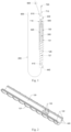
- the implant delivery system provided by the embodiment of the present invention is configured to deliver an implant into a diseased lumen such as a blood vessel.
- the stent 10 is used as an implant to be delivered for description, but it should not constitute a limitation to the present invention.
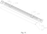
- the implant delivery system includes a handle 110, a first inner sliding member 120, a second inner sliding member 130, an outer tube 200, and a jacking tube 300.
- the handle 110 has a first cavity.
- the first inner sliding member 120 and the second inner sliding member 130 are located in the first cavity.
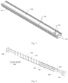
- the outer tube 200 has a first proximal end and a first distal end opposite to each other.
- the first proximal end is connected to the first inner sliding member 120.
- the jacking tube has a second proximal end and a second distal end opposite to each other.
- the second distal end is disposed in the outer tube, and the second proximal end is connected to the second inner sliding member 130.
- the handle 110 is threadedly matched with the first inner sliding member 120 and the second inner sliding member 130 for screw transmission, and is configured to drive the first inner sliding member 120 and the second inner sliding member 130 to move linearly along the axis of the handle 110 in two opposite directions, thereby driving the outer tube 200 and the jacking tube 300 to move in the two opposite directions.
- the stent 10 is delivered and released by the implant delivery system provided by the present invention.
- the first inner sliding member 120 can drive the outer tube 200 to withdraw by means of screw transmission, and the stent 10 is released with its volume expanded but length shortened, which results in a deviation from the predetermined position.
- the second inner sliding member 130 drives the jacking tube 300 to move to the predetermined position, thereby pushing the stent 10 to the predetermined position, so that the stent 10 is positioned accurately to ensure a treatment effect.
- the implant delivery system further includes a circumferential positioning member 400.
- the circumferential positioning member 400 is used to keep the first inner sliding member 120 and the second inner sliding member 130 fixed in the circumferential direction and moveable in the axial direction.
- the retracting distance of the outer tube 200 and the pushing distance of the jacking tube 300 need to meet a certain ratio, so that the stent 10 can accurately reach the predetermined position.
- the retracting distance of the outer tube 200 and the pushing distance of the jacking tube 300 can be calculated through simulation experiments.
- the retreating distance of the outer tube 200 is equal to the moving distance of the first inner sliding member 120
- the pushing distance of the jacking tube 300 is equal to the moving distance of the second inner sliding member 130.
- the moving distances of the first inner sliding member 120 and the second inner sliding member 130 rely on the rotation speed and the pitch.
- the first inner sliding member 120 and the second inner sliding member 130 are controlled to rotate by the same handle 110, and both have the same rotation speed.
- the moving distances of the first inner sliding member 120 and the second inner sliding member 130 are respectively determined by the respective pitch.
- the pitch ratio of the first inner sliding member 120 and the second inner sliding member 130 By setting the pitch ratio of the first inner sliding member 120 and the second inner sliding member 130, the first inner sliding member 120 and the second inner sliding member 130 can move according to an expected speed ratio, so that the retreating distance of the outer tube 200 and the pushing distance of the jacking tube 300 meets an expected ratio, so that the stent 10 can accurately reach the predetermined position.
- it is common knowledge to set the pitch ratio of the two threaded segments according to the ratio of the known moving distances so it will not be described in detail here.
- first inner sliding member 120 the second inner sliding member 130, and the handle 110 will be further described and illustrated in detail, but not limited to the structure described in the following embodiments.
- the outer surface of the first inner sliding member 120 is provided with a first external thread 121
- the outer surface of the second inner sliding member is provided with a second external thread 131.
- the thread directions of the first external thread 121 and the second external thread 131 are opposite.
- the first inner sliding member 120 may have an arc shape, preferably a semicircular arc shape
- the first external thread 121 is provided on the convex surface of the first inner sliding member 120.
- the second inner sliding member 130 may have an arc shape, preferably a semicircular arc shape.
- first inner sliding member 120 and the second inner sliding member 130 are both of semicircular arc shapes.
- the outer diameter of the second inner sliding member 130 is equal in length to the outer diameter of the first inner sliding member 120, and the inner diameters of the second inner sliding member 130 and the first inner sliding member 120 are also equal in length.
- the first inner sliding member and the second inner sliding member may have other shapes.
- the outer diameters of the first inner sliding member and the second inner sliding member can be the same or different.
- the second external thread 131 is provided on the convex surface of the second inner sliding member 130.
- the concave surface of the first inner sliding member 120 and the concave surface of the second inner sliding member 130 are arranged opposite to each other (that is, when the first inner sliding member 120 and the second inner sliding member 130 are projected to a plane perpendicular to the axial direction of the handle 110, the projections of the first inner sliding member 120 and the second inner sliding member 130 may form a circle).
- the first inner sliding member 120 and the second inner sliding member 130 are slidable relatively along the axial direction of the handle 110. During the sliding process, the first inner sliding member 120 and the second inner sliding member 130 may overlap at least partially. This structural design can reduce the axial length of the handle 110, reduce the size of the delivery system, and also make it easier to operate.
- first inner sliding member 120 has two first end surfaces extending along the axial direction of the handle 110, and each of the first end surface may be provided with a raised limiting member 122 extending along the axial direction of the handle 110.
- the second inner sliding member 130 has two second end surfaces extending along the axial direction of the handle 110, and each of the second end surfaces may be correspondingly provided with a sliding groove 132 extending along the axial direction of the handle 110.
- the raised limiting member 122 is installed in the sliding groove 132 and is slidable along the sliding groove 132 to realize the circumferential positioning of the first inner sliding member 120 and the second inner sliding member 130.
- the positions of the raised limiting member 122 and the sliding groove 132 can also be exchanged.
- the raised limiting member 122 is arranged on the second end surfaces of the second inner sliding member 130, and the sliding groove 132 is arranged on the first end surfaces of the first inner sliding member 120.
- the raised limiting member 122 can be a continuous member extending along the axial direction of the handle 110, or can be a plurality of members spaced apart along the axial direction of the handle 110.
- the first inner sliding member 120 can be provided with a raised limiting member on one of the first end surfaces, or can be provided with raised limiting members 122 on both of the first end surfaces; accordingly, the second inner sliding member 130 can be provided with a sliding groove 132 on one of the second end surfaces, or can be provided with sliding grooves on both of the second end surfaces.
- the raised limiting member and sliding grooves may not be provided, but the circumferential positioning between the first inner sliding member and the second inner sliding member is realized through specific structures.
- the circumferential positioning member 400 further includes positioning grooves 420 defined in the first inner sliding member 120 and the second inner sliding member 130, and the positioning grooves 420 extends along the axial direction of the handle 110.
- the first inner sliding member 120 and the second inner sliding member 130 are mounted to the arc-shaped plate 410 through the positioning grooves 420 and are slidable along the arc-shaped plate 410.
- two arc-shaped plates 410 are included, and the two arc-shaped plates 410 are arranged side by side and both extend along the axial direction of the handle 110.
- Each of the two first end surfaces of the first inner sliding member 120 is provided with a positioning groove 420, and each of the two second end surfaces of the second inner sliding member 130 is defined with a positioning groove 420.
- the arc-shaped plate 410 may be an arc-shaped plate structure, and is symmetrically arranged by the positioning grooves 420, so that the first inner sliding member 120 and the second inner sliding member 130 are balanced in force during movement.
- the fourth distal end of the inner tube 500 is further provided with a developing ring 520 to facilitate positioning of the stent 10.
- the number of the developing ring 520 may be one or more.
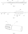
- the second distal end of the jacking tube 300 is provided with a head 310, and the head 310 has a holding structure 311.
- the holding structure 311 is used for holding and releasing the stent 10.
- the head 310 of the jacking tube is sleeved over the jacking tube 300, and the part of the jacking tube 300 away from the second distal end of the jacking tube 300 is preferably designed as an umbrella-shaped structure, and the outer surface of the umbrella-shaped structure is provided with the holding structure 311.
- the holding structure 311 is a hook, the number of the hook is at least two, and the at least two of the hooks can be arranged at intervals along the circumferential direction of the head 310 of the jacking tube.
- the second proximal end of the jacking tube 300 is provided with a jacking tube connection assembly 320 used to connect the jacking tube 300 with the inner tube 500, and the jacking tube connection assembly 320 is also used to connect with the second inner sliding member 130.
- the jacking tube connector 321 may further be defined with a second snap groove.
- a second snap ring 133 can be provided on the inner wall of the second inner sliding member 130.
- the jacking tube 300 can be detachably connected to the second inner sliding member 130 by means of the fit between the second snap groove and the second snap ring 133.
- the outer tube connector 211 may further be defined with a first snap groove, and the first inner sliding member 120 may be correspondingly provided with a first snap ring 123.
- the outer tube 200 can be detachably connected to the first inner sliding member 120 by means of the fit between the first snap groove and the first snap ring 123.
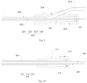
- the second infusion tube 810 is used to discharge the air between the outer tube 200 and the jacking tube 300 and the air between the jacking tube 300 and the inner tube 500.
- the arrangement of the second infusion tube may be selected from, but not limited to, the following two options:
- the first arrangement (not shown): the outer tube connector is provided with a first branch connector in wich a third connecting hole is defined.
- the second infusion tube is inserted in the third connecting hole.
- the end of the second infusion tube away from the first branch connector is provided with a check valve.
- the jacking tube connection assembly 320 further includes a second branch connector 324 in which a fourth connecting hole is defined.
- the second infusion tube 810 is inserted into the fourth connecting hole so that the jacking tube 300 is in communication with the second infusion tube 810.
- the end of the second infusion tube 810 away from the jacking tube connector 321 is provided with a check valve 820. It should be noted that various existing methods can be used to realize the fixed connection between the components when assembling the components.
- the guide member 600 may be injection molded on the fourth distal end of the inner tube 500, and the head 310 of the jacking tube may be injection molded on or in hot melt connection with the second distal end of the jacking tube 300, and the outer tube connector 211 may be injection molded on the first proximal end of the outer tube 200, the inner tube 500 and the first connecting sleeve 511 may be bonded by glue, the second infusion tube 810 and the second branch connector 324 may be bonded by glue.
- the stent 10 is first compressed into the outer tube 200; then a syringe is connected to the check valve 820, and a liquid such as heparin saline is injected into the implant delivery system by the syringe to discharge the air between the inner tube 500 and the jacking tube 300 as well as the air between the jacking tube 300 and the outer tube 200; and a syringe is connected to the Luer taper 720 to inject liquid into the inner tube 500 to discharge the air in the inner tube 500; the outer wall of the outer tube 200 is then cleaned by heparin saline.
- a liquid such as heparin saline
- the blood vessel is first punctured, and then under the supervision of the X-ray machine, the guide member 600 is sent to the area where the lesion locates by using a common means (such as a guide wire) to make the developing ring 520 coincide in position with the location where and the stent 10 is to be placed.
- a common means such as a guide wire
- the handle 110 is rotated to move the outer tube 200 proximally, and the stent 10 is released and expanded.
- the jacking tube 300 pushes the stent 10 to move distally so that the stent 10 is finally located at a predetermined position, and the guide member 600 is separated from the outer tube 200; the handle 110 is continuously rotated until the stent 10 is completely released.
- the locking cap 513 is released, and the first infusion tube 710 is pulled proximally to drive the inner tube 500 to move proximally until the guide member 600 contacts the outer tube 200 again, and finally the implant delivery system is withdrawn from the body.
- the first inner sliding member 120 and the second inner sliding member 130 are arc-shaped when viewed along the axial direction of the handle 110, which is taken as an example to describe the structure of the implant delivery system.
- structures of the first inner sliding member 120 and the second inner sliding member 130 are not limited thereto.
- the handle 110 has a first cavity extending axially with a cylinder shape, and the wall of the first cavity is formed with a first internal thread and a second internal thread, and the first internal thread and the second internal thread are arranged along the axial direction of the handle 110.
- the present invention does not strictly limit the specific structures of the first inner sliding member, the second inner sliding member, and the handle, as long as the first inner sliding member and the second inner sliding member can simultaneously move linearly in opposite directions in response to the rotation of the handle after they are threadedly connected to the handle.
- the advantage of the implant delivery system provided in the embodiments of the present invention is as follows.
- the outer tube 200 and the jacking tube 300 are simultaneously driven by the driving assembly 100 to move linearly in opposite directions, so that the stent 10 gradually moves from the distal end to the proximal end, and the stent 10 is pushed by the jacking tube 300 to move distally to supplement the displacement caused by the contraction of the stent 10 due to expansion, so that the stent 10 can be delivered to a predetermined position to ensure the treatment effect.
- the outer tube 200 and the jacking tube 300 are driven to move by means of screw feeding, which facilitates the control of the moving distance of the outer tube 200 and the jacking tube 300, so as to achieve accurat positioning of the stent 10 and reduced requirement for the operator's experience.
Landscapes
- Health & Medical Sciences (AREA)
- Engineering & Computer Science (AREA)
- Biomedical Technology (AREA)
- Cardiology (AREA)
- Oral & Maxillofacial Surgery (AREA)
- Transplantation (AREA)
- Heart & Thoracic Surgery (AREA)
- Vascular Medicine (AREA)
- Life Sciences & Earth Sciences (AREA)
- Animal Behavior & Ethology (AREA)
- General Health & Medical Sciences (AREA)
- Public Health (AREA)
- Veterinary Medicine (AREA)
- Media Introduction/Drainage Providing Device (AREA)
- Prostheses (AREA)
Claims (15)
- Einführungssystem für ein Implantat (10), umfassend: einen Handgriff (110), ein erstes inneres Gleitelement (120), ein zweites inneres Gleitelement (130), ein inneres Rohr (500), ein äußeres Rohr (200) und ein Vorschubrohr (300), wobei der Handgriff (110) einen ersten Hohlraum aufweist, in dem sich das erste innere Gleitelement (120) und das zweite innere Gleitelement (130) befinden;das äußere Rohr (200) ein erstes proximales Ende und ein erstes distales Ende aufweist, die einander gegenüberliegen, und das erste proximale Ende mit dem ersten inneren Gleitelement (120) verbunden ist; das Vorschubrohr (300) ein zweites proximales Ende und ein zweites distales Ende aufweist, die einander gegenüberliegen, das zweite distale Ende in dem äußeren Rohr (200) angeordnet ist, und das zweite proximale Ende mit dem zweiten inneren Gleitstück (130) verbunden ist; das innere Rohr (500) sich durch das äußere Rohr (200) und das Vorschubrohr (300) erstreckt und ein Hohlraum, der zum Aufnehmen eines Implantats (10) konfiguriert ist, zwischen dem inneren Rohr (500) und dem äußeren Rohr (200) gebildet ist; und das zweite distale Ende zum Verbinden mit einem proximalen Teil des Implantats (10) konfiguriert ist;der Handgriff (110) mit dem ersten inneren Gleitelement und dem zweiten inneren Gleitelement (130) zur Schraubenübertragung verschraubt ist und konfiguriert ist, um das erste innere Gleitelement (120) und das zweite innere Gleitelement (130) anzutreiben, um sich linear entlang einer Achse des Handgriffs (110) in entgegengesetzte Richtungen zu bewegen, um das äußere Rohr (200) und das Vorschubrohr (300) anzutreiben, um sich in die entgegengesetzten Richtungen zu bewegen, um das Implantat (10) von einem distalen Ende zu einem proximalen Ende davon zu lösen;wobei das Einführungssystem für ein Implantat (10) ferner ein proximales Verbinder (430) und ein distales Verbinder (440) umfasst, die an den jeweiligen Enden des Handgriffs (110) bereitgestellt sind, der proximale Verbinder (430) und der distale Verbinder (440) durch zwei bogenförmige Platten (410) mit konkaven Oberflächen verbunden sind, die einander gegenüberliegend angeordnet sind und einen zweiten Hohlraum definieren; der distale Verbinder (440) mit einem ersten Durchgangsloch versehen ist, das in axialer Richtung durchdringt; der proximale Verbinder (430) mit einem proximalen Ende des inneren Rohrs (500) verbunden ist;wobei eine Stellnut (420), die sich entlang einer axialen Richtung des Handgriffs (110) erstreckt, sowohl in dem ersten inneren Gleitelement (120) als auch in dem zweiten inneren Gleitelement (130) definiert ist, und das erste innere Gleitelement (120) und das zweite innere Gleitelement (130) durch die Stellnut (420) gleitend mit einer bogenförmigen Platte (410) verbunden sind; das Vorschubrohr (300) durch das erste Durchgangsloch verläuft.
- Einführungssystem für ein Implantat (10) nach Anspruch 1, wobei eine Außenfläche des ersten inneren Gleitelements (120) mit einem ersten Außengewinde (121) versehen ist, und eine Außenfläche des zweiten inneren Gleitelements (130) mit einem zweiten Außengewinde (131) versehen ist, wobei die Gewinderichtungen des ersten Außengewindes (121) und des zweiten Außengewindes (131) entgegengesetzt sind;
wobei eine Innenfläche des Handgriffs (110) mit einem ersten Innengewinde und einem zweiten Innengewinde versehen ist und das erste Innengewinde des Handgriffs (110) mit dem ersten Außengewinde (121) des ersten inneren Gleitelements (120) zur Schraubübertragung verschraubt ist, und das zweite Innengewinde des Handgriffs (110) mit dem zweiten Außengewinde (131) des zweiten inneren Gleitelements (130) zur Schraubübertragung verschraubt ist. - Einführungssystem für ein Implantat (10) nach Anspruch 1, wobei der Handgriff (110) zwei Teilhandgriffe (111) umfasst, die innere Hohlräume aufweisen, und jeder der inneren Hohlräume eine halbkreisförmige Bogenform in einem Querschnitt senkrecht zu einer axialen Richtung des Handgriffs (110) aufweist.
- Einführungssystem für ein Implantat (10) nach einem der Ansprüche 1 bis 3, wobei sowohl das erste innere Gleitelement (120) als auch das zweite innere Gleitelement (130) eine Bogenform, vorzugsweise eine halbkreisförmige Bogenform, in einem Querschnitt senkrecht zu der Achse des Handgriffs (110) aufweist, und eine konkave Fläche des ersten inneren Gleitelements (120) gegenüber einer konkaven Fläche des zweiten inneren Gleitelements (130) angeordnet ist.
- Einführungssystem für ein Implantat (10) nach Anspruch 1, wobei das erste innere Gleitelement (120) zwei erste Endflächen aufweist, die sich entlang der axialen Richtung des Handgriffs (110) erstrecken, die Stellnut (420) in jeder der zwei ersten Endflächen definiert ist, und das erste innere Gleitelement (120) durch die zwei Stellnuten (420) gleitend mit den zwei bogenförmigen Platten (410) verbunden ist; das zweite innere Gleitelement (130) zwei zweite Endflächen aufweist, die sich entlang der axialen Richtung des Handgriffs (110) erstrecken, die Stellnut (420) ferner in jeder der zwei zweiten Endflächen definiert ist, und das zweite innere Gleitelement (130) durch die zwei Stellnuten (420) gleitend mit den zwei bogenförmigen Platten (410) verbunden ist;
wobei die erste Endfläche mit einem erhabenen Begrenzungselement (122) versehen ist, die zweite Endfläche mit einer sich entlang der axialen Richtung des Handgriffs (110) erstreckenden Gleitnut (132) definiert ist und das Begrenzungselement in der Gleitnut (132) installiert ist; oder, die erste Endfläche mit einer Gleitnut definiert ist, die zweite Endfläche mit einem erhöhten Begrenzungselement (122) versehen ist, das sich entlang der axialen Richtung des Handgriffs (110) erstreckt, und das Begrenzungselement in der Gleitnut (132) installiert ist. - Einführungssystem für ein Implantat (10) nach Anspruch 1, wobei der proximale Verbinder (430) mit einem zweiten Durchgangsloch definiert ist, das in der axialen Richtung durchdringt, und das innere Rohr (500) sich durch das erste Durchgangsloch, den zweiten Hohlraum und das zweite Durchgangsloch erstreckt.
- Einführungssystem für ein Implantat (10) nach Anspruch 1, wobei die bogenförmige Platte (410) ein drittes proximales Ende und ein drittes distales Ende aufweist, die einander gegenüberliegen; ein erstes Sackloch in dem proximalen Verbinder (430) definiert ist, und das dritte proximale Ende der bogenförmigen Platte (410) in dem ersten Sackloch installiert ist; ein zweites Sackloch in dem distalen Verbinder (440) definiert ist und das dritte distale Ende der bogenförmigen Platte (410) in dem zweiten Sackloch installiert ist.
- Einführungssystem für ein Implantat (10) nach Anspruch 1, wobei ferner umfassend einen Kopf des Vorschubrohrs (310), der an dem zweiten distalen Ende des Vorschubrohrs (300) angeordnet ist, und der Kopf mit einer Haltestruktur zum Halten und Freigeben des Implantats (10) versehen ist;
wobei die Haltestruktur eine Vielzahl von Haken (311) umfasst, die entlang einer Umfangsrichtung des Kopfs des Vorschubrohrs (310) beabstandet sind. - Einführungssystem für ein Implantat (10) nach Anspruch 1, wobei ferner umfassend ein Führungselement (600) und das innere Rohr (500) ein viertes proximales Ende und ein viertes distales Ende aufweist, die einander gegenüberliegen, das vierte distale Ende des inneren Rohrs (500) über das erste distale Ende des äußeren Rohrs (200) hervorsteht und mit dem Führungselement (600) verbunden ist;
wobei ferner umfassend mindestens ein Entwicklungsring (520), das an dem vierten distalen Ende des inneren Rohrs (500) angeordnet ist. - Einführungssystem für ein Implantat (10) nach Anspruch 1, wobei ferner umfassend ein Führungselement (600) und das innere Rohr (500) ein viertes proximales Ende und ein viertes distales Ende aufweist, die einander gegenüberliegen, das vierte distale Ende des inneren Rohrs (500) über das erste distale Ende des äußeren Rohrs (200) hervorsteht und mit dem Führungselement (600) verbunden ist;wobei das erste proximale Ende des äußeren Rohrs (200) mit einer Außenwand des Vorschubrohrs (300) durch eine äußere Rohrverbindungsanordnung (210) verbunden ist und das äußere Rohr (200) entlang der Außenwand des Vorschubrohrs (300) verschiebbar ist;wobei die äußere Rohrverbindungsanordnung (210) einen äußeren Rohrverbinder (211), einen ersten Dichtungsring (212) und eine erste Dichtungskappe (213) umfasst; der äußeren Rohrverbinder (211) ein erstes Verbindungsloch aufweist, dessen eine Ende fest mit dem äußeren Rohr (200) verbunden ist, ein weiteres Ende über das Vorschubrohr (300) aufgesteckt ist; und der erste Dichtungsring (212) über das Vorschubrohr (300) aufgesteckt ist und in abdichtender Verbindung mit dem äußeren Rohr (200) ist, wenn die erste Dichtungskappe (213) angezogen ist.
- Einführungssystem für ein Implantat (10) nach Anspruch 10, wobei der äußere Rohrverbinder (211) ferner mit einer ersten Rastnut versehen ist, das erste innere Gleitelement (120) mit einem ersten Einrastring (123) versehen ist, und die erste Rastnut lösbar mit dem ersten Einrastring (123) verbunden ist.
- Einführungssystem für ein Implantat (10) nach Anspruch 10, wobei das zweite proximale Ende des Vorschubrohrs (300) mit einer Vorschubrohrverbindungsanordnung (320) versehen ist, umfassend einen Vorschubrohrverbinder (321), wobei das Vorschubrohrverbinder (321) an dem zweiten proximalen Ende des Vorschubrohrs (300) angeordnet ist und das Vorschubrohrverbinder (321) mit einem zweiten Verbindungsloch definiert ist, durch das das Vorschubrohrverbinder (321) über das innere Rohr (500) geschoben wird und entlang des inneren Rohrs (500) verschiebbar ist;
wobei die Verbindungsanordnung für das Vorschubrohr ferner einen zweiten Dichtungsring (322) und eine zweite Dichtungskappe (323) umfasst, der zweite Dichtungsring (322) über das innere Rohr (500) aufgesteckt wird, die zweite Dichtungskappe (323) zur Befestigung des zweiten Dichtungsrings (322) verwendet wird, sodass der Vorschubrohranschluss (321) in dichtender Verbindung mit dem inneren Rohr (500) ist. - Einführungssystem für ein Implantat (10) nach Anspruch 10, wobei das zweite proximale Ende des Vorschubrohrs (300) mit einer Vorschubrohrverbindungsanordnung (320) versehen ist, umfassend einen Vorschubrohrverbinder (321), wobei das Vorschubrohrverbinder (321) an dem zweiten proximalen Ende des Vorschubrohrs (300) angeordnet ist und das Vorschubrohrverbinder (321) mit einem zweiten Verbindungsloch definiert ist, durch das der Vorschubrohrverbinder (321) über das innere Rohr (500) geschoben wird und entlang des inneren Rohrs (500) verschiebbar ist;
wobei der Vorschubrohrverbinder (321) mit einer zweiten Rastnut versehen ist, das zweite innere Gleitelement (130) mit einem zweiten Einrastring (133) versehen ist und die zweite Rastnut lösbar mit dem zweiten Einrastring (133) verbunden ist. - Einführungssystem für ein Implantat (10) nach Anspruch 12, wobei umfassend ein erstes Infusionsrohr (710) und ein zweites Infusionsrohr (810); wobei das vierte proximale Ende des inneren Rohrs (500) aus dem zweiten proximalen Ende des Vorschubrohrs (300) hervorsteht und mit dem ersten Infusionsrohr (710) in Verbindung ist; der äußere Rohrverbinder (211) mit einem ersten Verzweigungsverbinder versehen ist und ein drittes Verbindungsloch in dem ersten Abzweigverbinder definiert ist und in Verbindung mit dem zweiten Infusionsrohr (810) ist; oder,der Vorschubrohrverbinder (321) mit einem zweiten Abzweigverbinder (324) versehen ist, und ein viertes Verbindungsloch in dem zweiten Abzweigverbinder (324) definiert ist und mit dem zweiten Infusionsrohr (810) in Verbindung ist;wobei das vierte proximale Ende des inneren Rohrs (500) mit einer innere Rohrverbindungsanordnung (510) versehen ist, die eine erste Verbindungsmuffe (511), eine zweite Verbindungsmuffe (512) und eine Verschlusskappe (513) umfasst; die erste Verbindungshülse (511) verwendet wird, um das innere Rohr (500) und das erste Infusionsrohr (710) zu verbinden, die zweite Verbindungshülse (512) auf die die erste Verbindungshülse (511) aufgesteckt und verwendet wird, um das vierte proximale Ende des inneren Rohrs (500) zu fixieren, und die Verriegelungskappe (513) verwendet wird, um die zweite Verbindungshülse (512), die erste Verbindungshülse (511) und das erste Infusionsrohr (710) in ihrer Position zu verriegeln.
- Einführungssystem für ein Implantat (10) nach einem der Ansprüche 1 bis 3, wobei das erste innere Gleitelement (120) und das zweite innere Gleitelement (130) als zwei koaxial zueinander angeordnete hohle röhrenförmige Strukturen gebildet sind.
Applications Claiming Priority (2)
| Application Number | Priority Date | Filing Date | Title |
|---|---|---|---|
| CN201911349231.2A CN110882096B (zh) | 2019-12-24 | 2019-12-24 | 一种植入物输送系统 |
| PCT/CN2020/113615 WO2021128940A1 (zh) | 2019-12-24 | 2020-09-04 | 一种植入物输送系统 |
Publications (3)
| Publication Number | Publication Date |
|---|---|
| EP4082491A1 EP4082491A1 (de) | 2022-11-02 |
| EP4082491A4 EP4082491A4 (de) | 2023-01-25 |
| EP4082491B1 true EP4082491B1 (de) | 2025-07-02 |
Family
ID=69752975
Family Applications (1)
| Application Number | Title | Priority Date | Filing Date |
|---|---|---|---|
| EP20905091.3A Active EP4082491B1 (de) | 2019-12-24 | 2020-09-04 | Implantateinführungssystem |
Country Status (8)
| Country | Link |
|---|---|
| EP (1) | EP4082491B1 (de) |
| JP (1) | JP7447273B2 (de) |
| KR (1) | KR102665074B1 (de) |
| CN (1) | CN110882096B (de) |
| AR (1) | AR120907A1 (de) |
| BR (1) | BR112022012539A2 (de) |
| ES (1) | ES3039937T3 (de) |
| WO (1) | WO2021128940A1 (de) |
Families Citing this family (5)
| Publication number | Priority date | Publication date | Assignee | Title |
|---|---|---|---|---|
| CN110882096B (zh) * | 2019-12-24 | 2024-11-15 | 上海蓝脉医疗科技有限公司 | 一种植入物输送系统 |
| CN113558834B (zh) * | 2021-08-09 | 2024-04-26 | 广东脉搏医疗科技有限公司 | 用于心血管植入物的连接组件 |
| CN116250970B (zh) * | 2023-03-31 | 2025-09-23 | 上海微创心通医疗科技有限公司 | 介入手柄与介入系统 |
| CN119700372A (zh) * | 2023-09-27 | 2025-03-28 | 深圳市健心医疗科技有限公司 | 一种用于输送器的支撑装置 |
| CN118892383B (zh) * | 2024-10-09 | 2025-01-24 | 北京华脉泰科医疗器械股份有限公司 | 深静脉血栓去除装置 |
Family Cites Families (17)
| Publication number | Priority date | Publication date | Assignee | Title |
|---|---|---|---|---|
| GB0203177D0 (en) * | 2002-02-11 | 2002-03-27 | Anson Medical Ltd | An improved control mechanism for medical catheters |
| KR100536405B1 (ko) * | 2002-09-09 | 2005-12-14 | 사회복지법인 삼성생명공익재단 | 카테타 미세 위치 조절기능이 부가된 관상동맥 확장장치 |
| US7691095B2 (en) * | 2004-12-28 | 2010-04-06 | St. Jude Medical, Atrial Fibrillation Division, Inc. | Bi-directional steerable catheter control handle |
| US8623064B2 (en) * | 2010-04-30 | 2014-01-07 | Medtronic Vascular, Inc. | Stent graft delivery system and method of use |
| CN102283728B (zh) * | 2011-06-28 | 2014-09-10 | 先健科技(深圳)有限公司 | 一种管腔支架输送系统 |
| US9393140B2 (en) * | 2012-04-27 | 2016-07-19 | Medtronic Vascular, Inc. | Reconfigurable stent-graft delivery system and method of use |
| JP6326648B2 (ja) * | 2012-08-10 | 2018-05-23 | アルツラ メディカル インコーポレイテッド | ステントデリバリシステム及び関連方法 |
| CN106308986B (zh) * | 2015-07-01 | 2018-06-01 | 微创心脉医疗科技(上海)有限公司 | 一种用于植入物输送系统的导管手柄 |
| CN106691648A (zh) * | 2016-12-20 | 2017-05-24 | 心凯诺医疗科技(上海)有限公司 | 一种可精确释放的自扩张支架输送系统 |
| CN109248012B (zh) * | 2017-07-14 | 2020-12-25 | 先健科技(深圳)有限公司 | 植入物的输送系统 |
| CN209075052U (zh) * | 2018-01-31 | 2019-07-09 | 常州乐奥医疗科技股份有限公司 | 自膨支架输送系统及其输送手柄 |
| CN209075051U (zh) | 2018-01-31 | 2019-07-09 | 常州乐奥医疗科技股份有限公司 | 自膨支架输送系统及其输送手柄 |
| CN108403269A (zh) * | 2018-03-07 | 2018-08-17 | 普霖医疗科技(广州)有限公司 | 一体式支架输送器 |
| US11517458B2 (en) * | 2018-04-05 | 2022-12-06 | Microvention, Inc. | Implant delivery system |
| CN211674738U (zh) * | 2019-12-24 | 2020-10-16 | 上海蓝脉医疗科技有限公司 | 一种植入物输送系统 |
| CN110882096B (zh) | 2019-12-24 | 2024-11-15 | 上海蓝脉医疗科技有限公司 | 一种植入物输送系统 |
| CN120907505A (zh) * | 2025-10-09 | 2025-11-07 | 江西省交投养护科技集团有限公司 | 一种改扩建路基沉降分析方法及系统 |
-
2019
- 2019-12-24 CN CN201911349231.2A patent/CN110882096B/zh active Active
-
2020
- 2020-09-04 ES ES20905091T patent/ES3039937T3/es active Active
- 2020-09-04 WO PCT/CN2020/113615 patent/WO2021128940A1/zh not_active Ceased
- 2020-09-04 KR KR1020227025323A patent/KR102665074B1/ko active Active
- 2020-09-04 EP EP20905091.3A patent/EP4082491B1/de active Active
- 2020-09-04 BR BR112022012539A patent/BR112022012539A2/pt unknown
- 2020-09-04 JP JP2022539003A patent/JP7447273B2/ja active Active
- 2020-12-23 AR ARP200103654A patent/AR120907A1/es active IP Right Grant
Also Published As
| Publication number | Publication date |
|---|---|
| CN110882096A (zh) | 2020-03-17 |
| KR20220119679A (ko) | 2022-08-30 |
| WO2021128940A1 (zh) | 2021-07-01 |
| CN110882096B (zh) | 2024-11-15 |
| EP4082491A4 (de) | 2023-01-25 |
| ES3039937T3 (en) | 2025-10-27 |
| BR112022012539A2 (pt) | 2022-09-06 |
| JP7447273B2 (ja) | 2024-03-11 |
| EP4082491A1 (de) | 2022-11-02 |
| JP2023508958A (ja) | 2023-03-06 |
| AR120907A1 (es) | 2022-03-30 |
| KR102665074B1 (ko) | 2024-05-20 |
Similar Documents
| Publication | Publication Date | Title |
|---|---|---|
| EP4082491B1 (de) | Implantateinführungssystem | |
| US11950807B2 (en) | Puncturing device and anchoring device | |
| CN106963516B (zh) | 腔内原位开窗穿刺装置 | |
| EP3398568B1 (de) | Einführungssystem und lumenstentsystem | |
| EP4458388A1 (de) | Interventionelle injektionsvorrichtung und interventionelles injektionssystem | |
| CN109953843B (zh) | 主动脉支架的输送释放装置 | |
| CN110974502B (zh) | 输送器以及植入件输送系统 | |
| CN211674738U (zh) | 一种植入物输送系统 | |
| CN110025415B (zh) | 一种医用植入物释放系统的手柄 | |
| RU2741702C2 (ru) | Устройство для внутривенной терапии с направляющим гибким проводным элементом | |
| CN111067682A (zh) | 用于控制植入式器械释放的组件及系统 | |
| CN118512285B (zh) | 一种可控弯主动脉瓣膜输送系统 | |
| CN107518968A (zh) | 自膨胀支架输送系统及其齿轮驱动组件 | |
| US20190313975A1 (en) | Imaging catheter assembly | |
| EP3219262A1 (de) | Vorrichtung und system für robotische embolisierung | |
| CN112315638A (zh) | 一种支架输送系统 | |
| CN108245291A (zh) | 自膨胀支架输送系统及其导管组件 | |
| EP2968752B1 (de) | Zelleninjektionsnadel | |
| CN116115402B (zh) | 一种输送器的近端结构及输送系统 | |
| CN209392164U (zh) | 输送系统 | |
| CN114983632B (zh) | 双向移动释放的心脏瓣膜输送系统 | |
| CN118141568A (zh) | 穿刺扩张组件及瓣膜输送系统 | |
| CN116407383A (zh) | 输送装置 | |
| CN119523705B (zh) | 一种输送器手柄及其输送系统 | |
| CN121015357A (zh) | 植介入式医疗器械输送器及输送组件 |
Legal Events
| Date | Code | Title | Description |
|---|---|---|---|
| STAA | Information on the status of an ep patent application or granted ep patent |
Free format text: STATUS: THE INTERNATIONAL PUBLICATION HAS BEEN MADE |
|
| PUAI | Public reference made under article 153(3) epc to a published international application that has entered the european phase |
Free format text: ORIGINAL CODE: 0009012 |
|
| STAA | Information on the status of an ep patent application or granted ep patent |
Free format text: STATUS: REQUEST FOR EXAMINATION WAS MADE |
|
| 17P | Request for examination filed |
Effective date: 20220708 |
|
| AK | Designated contracting states |
Kind code of ref document: A1 Designated state(s): AL AT BE BG CH CY CZ DE DK EE ES FI FR GB GR HR HU IE IS IT LI LT LU LV MC MK MT NL NO PL PT RO RS SE SI SK SM TR |
|
| A4 | Supplementary search report drawn up and despatched |
Effective date: 20221223 |
|
| RIC1 | Information provided on ipc code assigned before grant |
Ipc: A61F 2/95 20130101ALI20221219BHEP Ipc: A61F 2/966 20130101AFI20221219BHEP |
|
| DAV | Request for validation of the european patent (deleted) | ||
| DAX | Request for extension of the european patent (deleted) | ||
| GRAP | Despatch of communication of intention to grant a patent |
Free format text: ORIGINAL CODE: EPIDOSNIGR1 |
|
| STAA | Information on the status of an ep patent application or granted ep patent |
Free format text: STATUS: GRANT OF PATENT IS INTENDED |
|
| INTG | Intention to grant announced |
Effective date: 20250410 |
|
| GRAS | Grant fee paid |
Free format text: ORIGINAL CODE: EPIDOSNIGR3 |
|
| GRAA | (expected) grant |
Free format text: ORIGINAL CODE: 0009210 |
|
| STAA | Information on the status of an ep patent application or granted ep patent |
Free format text: STATUS: THE PATENT HAS BEEN GRANTED |
|
| AK | Designated contracting states |
Kind code of ref document: B1 Designated state(s): AL AT BE BG CH CY CZ DE DK EE ES FI FR GB GR HR HU IE IS IT LI LT LU LV MC MK MT NL NO PL PT RO RS SE SI SK SM TR |
|
| REG | Reference to a national code |
Ref country code: GB Ref legal event code: FG4D |
|
| REG | Reference to a national code |
Ref country code: CH Ref legal event code: EP |
|
| REG | Reference to a national code |
Ref country code: DE Ref legal event code: R096 Ref document number: 602020054009 Country of ref document: DE |
|
| REG | Reference to a national code |
Ref country code: IE Ref legal event code: FG4D |
|
| PGFP | Annual fee paid to national office [announced via postgrant information from national office to epo] |
Ref country code: DE Payment date: 20250919 Year of fee payment: 6 |
|
| PGFP | Annual fee paid to national office [announced via postgrant information from national office to epo] |
Ref country code: GB Payment date: 20250919 Year of fee payment: 6 |
|
| REG | Reference to a national code |
Ref country code: ES Ref legal event code: FG2A Ref document number: 3039937 Country of ref document: ES Kind code of ref document: T3 Effective date: 20251027 |
|
| REG | Reference to a national code |
Ref country code: NL Ref legal event code: MP Effective date: 20250702 |