EP4080860B1 - Elektronische vorrichtung - Google Patents
Elektronische vorrichtung Download PDFInfo
- Publication number
- EP4080860B1 EP4080860B1 EP22732886.1A EP22732886A EP4080860B1 EP 4080860 B1 EP4080860 B1 EP 4080860B1 EP 22732886 A EP22732886 A EP 22732886A EP 4080860 B1 EP4080860 B1 EP 4080860B1
- Authority
- EP
- European Patent Office
- Prior art keywords
- dial plate
- electronic device
- disposed
- angle
- induction
- Prior art date
- Legal status (The legal status is an assumption and is not a legal conclusion. Google has not performed a legal analysis and makes no representation as to the accuracy of the status listed.)
- Active
Links
Images







Classifications
-
- H—ELECTRICITY
- H04—ELECTRIC COMMUNICATION TECHNIQUE
- H04M—TELEPHONIC COMMUNICATION
- H04M1/00—Substation equipment, e.g. for use by subscribers
- H04M1/02—Constructional features of telephone sets
- H04M1/0202—Portable telephone sets, e.g. cordless phones, mobile phones or bar type handsets
- H04M1/026—Details of the structure or mounting of specific components
- H04M1/0264—Details of the structure or mounting of specific components for a camera module assembly
-
- H—ELECTRICITY
- H04—ELECTRIC COMMUNICATION TECHNIQUE
- H04M—TELEPHONIC COMMUNICATION
- H04M1/00—Substation equipment, e.g. for use by subscribers
- H04M1/02—Constructional features of telephone sets
- H04M1/23—Construction or mounting of dials or of equivalent devices; Means for facilitating the use thereof
- H04M1/233—Construction or mounting of dials or of equivalent devices; Means for facilitating the use thereof including a pointing device, e.g. roller key, track ball, rocker switch or joystick
-
- H—ELECTRICITY
- H04—ELECTRIC COMMUNICATION TECHNIQUE
- H04M—TELEPHONIC COMMUNICATION
- H04M1/00—Substation equipment, e.g. for use by subscribers
- H04M1/02—Constructional features of telephone sets
- H04M1/0202—Portable telephone sets, e.g. cordless phones, mobile phones or bar type handsets
- H04M1/0279—Improving the user comfort or ergonomics
- H04M1/0281—Improving the user comfort or ergonomics for providing single handed use or left/right hand conversion
-
- H—ELECTRICITY
- H04—ELECTRIC COMMUNICATION TECHNIQUE
- H04M—TELEPHONIC COMMUNICATION
- H04M1/00—Substation equipment, e.g. for use by subscribers
- H04M1/02—Constructional features of telephone sets
- H04M1/0202—Portable telephone sets, e.g. cordless phones, mobile phones or bar type handsets
- H04M1/0279—Improving the user comfort or ergonomics
- H04M1/0283—Improving the user comfort or ergonomics for providing a decorative aspect, e.g. customization of casings, exchangeable faceplate
-
- H—ELECTRICITY
- H04—ELECTRIC COMMUNICATION TECHNIQUE
- H04M—TELEPHONIC COMMUNICATION
- H04M1/00—Substation equipment, e.g. for use by subscribers
- H04M1/02—Constructional features of telephone sets
- H04M1/23—Construction or mounting of dials or of equivalent devices; Means for facilitating the use thereof
- H04M1/236—Construction or mounting of dials or of equivalent devices; Means for facilitating the use thereof including keys on side or rear faces
Definitions
- This application relates to the technical field of electronic devices.
- US 2019/212830 A1 relates to a camera module mounted to a mobile device, the camera module comprising: a main lens disposed to a back surface of the mobile device; at least one function key disposed to the back surface of the mobile device and adjacent to the main lens, the function key being connected to a control system of the mobile device; wherein the function key corresponds to at least one control command of the control system when the function key is triggered.
- the function key presents an annular structure and surrounds a periphery of the main lens.
- the function key is triggered by circumferentially rotating along the main lens.
- the control command to which the function key corresponds may include at least two types, one of which type is triggered when the function key rotates clockwise, and the other of which type is triggered when the function key rotates counterclockwise.
- An objective of this application is to provide an electronic device to resolve the existing problem of relatively inconvenient operation of an electronic device such as a mobile phone.
- the electronic device includes a rear cover and a camera decoration component that are fixedly connected.
- the camera decoration component includes a decoration member, a dial plate, a plurality of positioning members and a plurality of induction members; the dial plate is annular, and is sleeved on an outer peripheral side of the decoration member; and the decoration member includes a virtual rotation axis, and the dial plate is rotatably connected to the decoration member, and is configured to rotate around the virtual rotation axis of the decoration member.
- the plurality of positioning members are fixed to the decoration member and are disposed toward the dial plate, the plurality of positioning members are disposed at equal intervals along a circumferential direction of the virtual rotation axis, the plurality of induction members are fixed to the dial plate and are disposed toward the decoration member, and the plurality of induction members are disposed at equal intervals along the circumferential direction of the virtual rotation axis.
- the virtual rotation axis is used as a center of a circle, an angle between two adjacent positioning members is ⁇ , an angle between two adjacent induction members is ⁇ , and there is an integer multiple relationship between the angle ⁇ and the angle ⁇ ; and during directly facing each other, the positioning member and the induction member are configured to control the dial plate to be in a hovering state.
- the electronic device includes a dial plate that is relatively rotatable, to make it convenient for a user to dial. Based on this, by dialing the dial plate, an interaction function of the electronic device may be expanded to enrich the user experience in different use scenarios. For example, by dialing the dial plate, functions such as swiping a display page or flipping a display page may be implemented to expand man-machine interaction manners and help the user obtain related information of the display page conveniently and quickly.
- the plurality of induction members is made of magnetic iron, and the plurality of positioning members is made of magnetic metal or magnetic iron. Alternatively, the plurality of induction members is made of magnetic metal, and the plurality of positioning members is made of magnetic iron.
- the electronic device further includes a sensor, and the sensor directly faces the dial plate, and is configured to obtain motion information of the dial plate during rotation. It should be understood that, through the cooperation between the dial plate and the related sensor, motion information such as a rotation direction and a rotation angle during dialing of the dial plate may be obtained, thereby triggering related functions of software to facilitate the expansion of man-machine interaction functions.
- the decoration member includes a main body portion and an annular bearing portion, and the bearing portion is located on an outer side of the main body portion and is disposed around the main body portion; and the plurality of positioning members are disposed at equal intervals along a circumferential direction of the bearing portion.
- a material of the decoration member may be aluminum alloy or the like, and a material of the dial plate may be, for example, aluminum alloy or stainless steel.
- the bearing portion includes a plurality of first mounting grooves disposed at equal intervals, and each of the positioning members is correspondingly mounted in each of the first mounting grooves; and the dial plate is disposed on the bearing portion and is rotatably connected to the main body portion, the dial plate includes a plurality of second mounting grooves disposed at equal intervals, and each of the induction members is correspondingly mounted in each of the second mounting grooves. Based on the first mounting groove and the second mounting groove, thicknesses of the dial plate, the camera decoration component, and the like may be better controlled while the induction member and the positioning member are correspondingly mounted.
- the camera decoration component When the camera decoration component is applied to an electronic device, while expanding the interaction functions, space occupied by the interior of the electronic device may be reduced and a thickness of the camera decoration component protruding from the rear cover may be controlled, so that an overall thickness of the electronic device may be easily controlled.
- the main body portion is provided with a boss in an axial direction along the virtual rotation axis, and the boss protrudes relative to the dial plate. It should be understood that the boss may protrude relative to the dial plate to protect the dial plate to a certain extent and reduce the possibility that the dial plate is bumped and deformed by a force.
- the positioning member is made of magnetic metal
- the induction member is made of magnetic iron
- the sensors are Hall sensors.
- the Hall sensor When the dial plate is in the hovering state, the Hall sensor directly faces the induction member, and the Hall sensor is configured to obtain magnetic field change information of the induction member that moves synchronously during movement of the dial plate. It should be understood that when the dial plate rotates, the Hall sensor senses a change of a magnetic field, and information such as the rotation direction and the rotation angle of the dial plate may be obtained to trigger the corresponding function of software.
- the quantity of the Hall sensors is N, and the plurality of positioning members and the N Hall sensors are circumferentially disposed around the bearing portion as a whole.
- the dial plate includes a top surface and a bottom surface opposite to each other, and the bottom surface faces the bearing portion.
- a side of the dial plate facing the bottom surface is provided with an identification texture; and the sensor is a texture sensor, and the texture sensor is configured to obtain texture information of the identification texture that moves synchronously during movement of the dial plate. It should be understood that, based on the analysis of the texture information, motion information such as the rotation direction and the rotation angle of the dial plate may be determined.
- the identification texture includes a plurality of grooves or a plurality of protrusions, and the plurality of grooves or the plurality of protrusions are disposed at equal intervals along the circumferential direction of the virtual rotation axis.
- texture information such as depth or roughness of the groove obtained by the texture sensor is also different. Based on this, according to the texture information of the groove and intervals between the grooves, the rotation direction and the rotation angle of the dial plate that is dialed may be determined, so as to facilitate execution of a related program.
- each of the grooves or each of the protrusions includes a first surface, a second surface and a third surface that are sequentially connected; and there is an inclination angle ⁇ between the first surface and the second surface, there is an inclination angle ⁇ between the second surface and the third surface, and the inclination angle ⁇ and the inclination angle ⁇ are different in magnitude.
- the identification texture includes a plurality of groups of identification stripes with a gradual change in lengths, and the plurality of groups of identification stripes are disposed along a circumferential direction of the dial plate. It should be understood that the length refers to a size of the identification stripe in a radial direction of the dial plate, and the gradual change may include gradual increase or gradual decrease.
- the camera decoration component further includes a sliding member, and the sliding member is sandwiched between the dial plate and the bearing portion, and is spaced apart from the positioning member.
- the sliding member may support the dial plate, and may improve the user's operation hand feeling when dialing the dial plate.
- the camera decoration component is provided with a Teflon tape on a surface of the sliding member. Based on this, a friction coefficient of a sliding sheet may be reduced, service life of the sliding sheet may be prolonged, and the operation hand feeling may be improved.
- the decoration member includes a first groove disposed along the circumferential direction of the virtual rotation axis
- the dial plate includes a second groove disposed along the circumferential direction of the virtual rotation axis, and the second groove directly faces the first groove.
- the camera decoration component further includes a gasket; and the gasket is sandwiched between the first groove and the second groove, and is configured to implement rotatable connection between the dial plate and the decoration member.
- the gasket includes an annular portion, a first buckling portion, and a second buckling portion; and the first buckling portion is located on an inner side of the annular portion, and the second buckling portion is located on an outer side of the annular portion and is disposed alternately with the first buckling portion, where the first buckling portion is at least partially disposed in the first groove, and the second buckling portion is at least partially disposed in the second groove.
- the gasket is elastically deformed and is sleeved on the decoration member, and sizes of the gasket in a radial direction may be further kept substantially the same, reducing the possibility that the gasket breaks under an external force, so that the service life of the gasket is prolonged.
- the positioning member includes an elastic member and a ball, the elastic member and the ball are sequentially disposed in the first mounting groove, and the elastic member is pressed between the bearing portion and the ball, where in a case that the ball is engaged with the second mounting groove, the dial plate is controlled to be in the hovering state.
- the induction member may be completely accommodated in the second mounting groove, so that the ball may be engaged with a notch of the second mounting groove, thereby implementing hovering.
- the ball when the dial plate is dialed, the ball is disengaged from the second mounting groove, and as the ball comes into contact with the bottom surface of the dial plate, the ball also rolls along with the rotation of the dial plate, so that a mechanical sound of dialing the dial plate is generated and the user experience is satisfied.
- the camera decoration component includes a rear cover and a camera decoration component that are fixedly connected.
- the camera decoration component includes a decoration member, a dial plate, a plurality of positioning members and a plurality of induction members; the dial plate is annular, and is sleeved on an outer peripheral side of the decoration member; and the decoration member includes a virtual rotation axis, and the dial plate is rotatably connected to the decoration member, and is configured to rotate around the virtual rotation axis of the decoration member.
- the plurality of positioning members are fixed to the decoration member and are disposed toward the dial plate, the plurality of positioning members are disposed at equal intervals along a circumferential direction of the virtual rotation axis, the plurality of induction members are fixed to the dial plate and are disposed toward the decoration member, and the plurality of induction members are disposed at equal intervals along the circumferential direction of the virtual rotation axis.
- the virtual rotation axis is used as a center of a circle, an angle between two adjacent positioning members is ⁇ , an angle between two adj acent induction members is ⁇ , and there is an integer multiple relationship between the angle ⁇ and the angle ⁇ ; and during directly facing each other, the positioning member and the induction member are configured to control the dial plate to be in a hovering state.
- the electronic device includes a dial plate that is relatively rotatable, to make it convenient for a user to dial.
- the camera decoration component may be applied to an electronic device and be used as a part of the electronic device.
- an interaction function of the electronic device may be expanded to enrich the user experience in different use scenarios. For example, by dialing the dial plate, functions such as swiping a display page or flipping a display page may be implemented to expand man-machine interaction manners and help the user obtain related information of the display page conveniently and quickly.
- the interaction function of the electronic device may be expanded while the dial plate is dialed by the user, so as to improve the user experience of the electronic device and help the user implement functions such as one-handed operation.
- a screen-to-body ratio is also gradually increasing. While satisfying the visual experience, it is increasingly inconvenient for a user to perform related operations through a screen of a mobile phone. For example, the user may not be capable of holding the mobile phone well with one hand. When performing an operation such as switching a photographing mode, changing a screen zoom ratio, or the like, the operation may need to be implemented in cooperation with the other hand. In electronic devices such as a tablet computer, because a screen size of the tablet computer is originally relatively large, many operations performed by the user are each implemented by two hands.
- electronic devices such as a mobile phone and a tablet computer have relatively few physical buttons. Therefore, these electronic devices also have relatively few functions that can be expanded through the physical buttons, and an actual experience effect of the user is also relatively poor.
- the mobile phone may generally include a power button and a volume button.
- the user may perform operations such as screening off and powering on and off through the power button; or the user may perform operations such as adjusting the volume and flipping a page through the volume button.
- functions expanded in a mobile phone based on these physical buttons are relatively limited, and cannot well meet the user's use requirements in different scenarios.
- the screen size of the mobile phone is increased.
- Embodiments of this application provide an electronic device 10, and the electronic device 10 includes a dial plate 120 and a decoration member 110 that are rotatably connected.
- the decoration member 110 may be a part of a camera decoration component 100.
- the dial plate 120 may rotate relative to the decoration member 110 of a camera.
- the operation possibility of the electronic device 10 may be expanded, thereby enriching the user's interaction requirements in different use scenarios. For example, by dialing the dial plate 120, functions such as swiping a display page or flipping a display page may be implemented to expand man-machine interaction manners and help the user obtain related information of the display page conveniently and quickly.
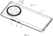
- the electronic device 10 includes a rear cover 16 and in some embodiments, a front cover 12, and a middle bezel 14, .
- the front cover 12 may be a transparent cover plate to facilitate light emission.
- a material of the front cover 12 may be glass or the like.
- the middle bezel 14 may be connected between the front cover 12 and the rear cover 16 to cooperate with the front cover 12 and the rear cover 16 to surround and form the interior of the electronic device 10, and may improve the structural strength of the electronic device 10.
- a material of the middle bezel 14 may be plastic, metal, or the like.
- the middle bezel 14 may be an aluminum alloy middle bezel 14.
- the rear cover 16 may be a transparent or non-transparent cover plate, and a material of the rear cover 16 may be glass, ceramic, metal, or the like.
- the electronic device 10 may further include a volume button 22 and a power button 24, and the volume button 22 and the power button 24 may be disposed inside the electronic device 10.
- the middle bezel 14 is provided with holes (not shown in the figure) corresponding to the volume button 22 and the power button 24. Based on this, the volume button 22 and the power button 24 may partially protrude from the middle bezel 14 so as to respond to the user's related operations and execute a related program.
- volume button 22 may be further removed from the electronic device 10, and functions such as volume adjustment are implemented through the dial plate 120; or the dial plate 120 may cooperate with the power button 24 to implement functions such as quick screenshot and quick screen recording.
- the electronic device 10 may further include a front camera component 26.
- the front camera component 26 may be placed inside the electronic device 10 and face the front cover 12, so as to implement functions such as face recognition, video chat, and the like.
- the electronic device 10 further includes a camera decoration component 100, and the camera decoration component 100 is fixedly connected to the rear cover 16.
- a fixed connection manner may include bonding by an adhesive and fixing by dispensing, which is not limited in this application.
- the camera decoration component 100 may be located in an upper-middle region of the rear cover 16, for example, in the upper-middle region of the rear cover 16 of the mobile phone, so as to help the user dial.
- the camera decoration component 100 may be fixed in other regions of the rear cover 16 according to actual requirements, in addition to being located in the upper-middle region of the rear cover 16, which is not limited.
- the electronic device 10 is a tablet computer or another electronic device 10 with a relatively large screen size
- the camera decoration component 100 may be located at an upper left corner or an upper right corner of the rear cover 16, so as to help the user dial.
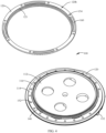
- the camera decoration component 100 is provided with a dial plate 120 on an outer peripheral side of the decoration member 110.
- the dial plate 120 is substantially annular in shape, and is rotatably connected to the decoration member 110. It should be understood that the dial plate 120 may rotate around the decoration member 110 when being dialed.
- the rotation of the dial plate 120 may be understood as self-rotation of the dial plate 120. That is, the decoration member 110 includes a virtual rotation axis P, and the dial plate 120 may rotate around the rotation axis when being dialed.
- a direction along the virtual rotation axis P may be understood as an axial direction
- a direction along the self-rotation/rotation of the dial plate 120 may be understood as a circumferential direction
- a direction perpendicular to the axial direction may be understood as a radial direction.
- the electronic device 10 may further include a related sensor, for example, the sensor in FIG. 2 is, but is not limited to, a Hall sensor 132.
- a related sensor for example, the sensor in FIG. 2 is, but is not limited to, a Hall sensor 132.
- motion information such as a rotation direction and a rotation angle during dialing of the dial plate 120 may be obtained, thereby triggering related functions of software and meeting the user's use requirement.
- motion information such as speed/angular velocity during dialing of the dial plate 120 may be further obtained, so as to expand man-machine interaction functions.
- the decoration member 110 includes a main body portion 112 and a bearing portion 114 surrounding the main body portion 112.
- a shape of the main body portion 112 is substantially cylindrical, and the bearing portion 114 is located on an outer side of the main body portion 112 and is disposed around the main body portion 112.
- a shape of the bearing portion 114 is substantially annular, and structures such as the dial plate 120 may be disposed on the bearing portion.
- a material of the decoration member 110 may be aluminum alloy, or the like, and a material of the dial plate 120 may be, for example, aluminum alloy or stainless steel, which is not limited.
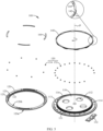
- the camera decoration component 100 further includes a gasket 140.
- the gasket 140 is disposed on the bearing portion 114 of the decoration member 110 and is sandwiched between the main body portion 112 and the dial plate 120.
- a material of the gasket 140 may be POM (Polyoxymethylene, Polyoxymethylene), PET, or the like.
- the gasket 140 may include an annular portion 142, a first buckling portion 144, and a second buckling portion 146.
- the first buckling portion 144 is located on an inner side of the annular portion 142
- the second buckling portion 146 is located on an outer side of the annular portion 142.
- the first buckling portion 144 and the second buckling portion 146 are disposed alternately.
- the gasket 140 is elastically deformed and is sleeved on the decoration member 110, and sizes of the gasket 140 in a radial direction may be further kept substantially the same, reducing the possibility that the gasket 140 breaks under an external force, so that service life of the gasket 140 may be further prolonged.
- a first groove 111 may be disposed on an outer side of the main body portion 112.
- the first groove 111 may be disposed along a circumferential direction of the virtual rotation axis P, and may be configured to implement the rotatable connection between the decoration member 110 and the dial plate 120.
- the dial plate 120 is further provided with a second groove 121.
- the second groove 121 may be disposed along a circumferential direction of the virtual rotation axis P, and may be opposite to the first groove 111 of the decoration member 110. Based on this, the first buckling portion 144 of the gasket 140 may at least partially extend into the first groove 111, and the second buckling portion 146 of the gasket 140 may also at least partially extend into the second groove 121. In this way, the dial plate 120 may be mounted on the decoration member 110, and the rotatable connection between the dial plate 120 and the decoration member 110 may be implemented.
- the main body portion 112 is provided with a boss 116 in an axial direction along the virtual rotation axis P, and the boss 116 is disposed around an inner side of the dial plate 120. It should be understood that after the dial plate 120 is mounted, the boss 116 may protrude relative to the dial plate 120. Based on this, the boss 116 may protect the dial plate 120 to a certain extent, so as to reduce the possibility that the dial plate 120 is bumped and deformed by a force.
- the electronic device 10 may further include a camera (not shown in the figure) and a glass sheet (not shown in the figure), and the camera decoration component is disposed between the camera and the glass sheet.
- the main body portion 112 of the decoration member 110 may be equipped with the glass sheet, so as to cooperate with the glass sheet to protect the camera.
- the main body portion 112 is further provided with a through hole (not marked) in a region corresponding to the glass sheet, and the through hole may directly face a lens of the camera, so that the camera may obtain external information.
- the boss 116 may be located between the glass sheet and the dial plate 120; and similarly, the boss 116 may protrude relative to the glass sheet, so as to reduce the possibility that the glass sheet is bumped and worn.
- the dial plate 120 includes a top surface 120a and a bottom surface 120b opposite to each other.
- the top surface 120a is a surface of the dial plate 120 away from the bearing portion 114, and is also a surface of the dial plate 120 that the user may touch; and the bottom surface 120b is a surface of the dial plate 120 facing the bearing portion 114.
- the top surface 120a of the dial plate 120 may include a texture to increase a frictional force when the user comes into contact with the dial plate 120.
- the dial plate 120 may further include a side surface.
- the side surface may be connected between the top surface 120a and the bottom surface 120b, and is also a surface of the dial plate 120 that the user may touch. Similar to the top surface 120a, the side surface may also include a texture to help the user dial the dial plate 120.
- the top surface 120a of the dial plate 120 may be an inclined surface inclined relative to the bottom surface 120b, and the side surface is perpendicular to the bottom surface 120b; and a cross-section of the dial plate 120 is trapezoidal as a whole.
- the top surface 120a of the dial plate 120 may be an inclined surface inclined relative to the bottom surface 120b, and is directly connected to the bottom surface 120b; and a cross-section of the dial plate 120 is triangular as a whole.
- the top surface 120a of the dial plate 120 may be an arc-shaped surface, and the top surface 120a is curved and is directly connected to the bottom surface 120b.
- the dial plate 120 may not include the side surface in the foregoing embodiments.
- the camera decoration component 100 further includes a hovering mechanism 150, and the hovering mechanism 150 may enable the dial plate 120 to hover after rotating by a preset angle. For example, under an external force and in cooperation with the hovering mechanism 150, every time the dial plate 120 rotates by 9°, 10°, 20°, 30°, or 45°, the dial plate hovers once. It should be understood that the preset angle may be different according to a setting of the hovering mechanism 150, which is not limited.
- the hovering mechanism 150 includes a positioning member 152 and an induction member 154, at least one of the positioning member 152 and the induction member 154 is made of magnetic iron, and the other is a structure that may generate a magnetic force with the magnet. Based on this, through the cooperation between the positioning member 152 and the induction member 154, hovering of the dial plate 120 may be implemented, and the user's operation hand feeling may be improved.
- the induction member 154 may be made of magnetic iron, and the positioning member 152 may be made of magnetic metal, but is not limited thereto. In some other embodiments, the induction member 154 may be made of magnetic metal, and the positioning member 152 may be made of magnetic iron; or the induction member 154 and the positioning member 152 may both be made of magnetic iron.
- the magnetic metal may be, for example, iron, nickel, cobalt, or the like.
- a side of the bearing portion 114 of the decoration member 110 facing the dial plate 120 is provided with a first mounting groove 113, and the positioning member 152 is disposed in the first mounting groove 113 and correspondingly faces the dial plate 120; and a side of the dial plate 120 facing the bearing portion 114 is provided with a second mounting groove 123, and the induction member 154 is disposed in the second mounting groove 123 and correspondingly faces the bearing portion 114 of the decoration member 110.
- thicknesses of the dial plate 120, the camera decoration component 100, and the like may be further better controlled while the induction member 154 and the positioning member 152 are correspondingly mounted.
- the camera decoration component 100 is applied to an electronic device 10
- space occupied by the interior of the electronic device 10 may be reduced and a thickness of the camera decoration component 100 protruding from the rear cover 16 may be controlled, so that an overall thickness of the electronic device 10 may be easily controlled.
- the induction member 154 made of magnetic iron and the positioning member 152 made of magnetic metal as an example, there are a plurality of induction members 154, and the plurality of induction members 154 are evenly disposed around the dial plate 120.
- the plurality of induction members 154 may be symmetrically and regularly disposed around the dial plate 120. Along the circumferential direction of the dial plate 120, the plurality of induction members 154 are disposed at equal intervals along the circumferential direction of the virtual rotation axis P. Alternatively, in other examples useful for understanding the invention, the plurality of induction members 154 may not be all disposed at equal intervals along the circumferential direction of the virtual rotation axis P. It should be understood that in this embodiment, a distance between each two adjacent induction members 154 is approximately the same, and within an allowable range of error, rotation and hovering of the dial plate 120 may also be implemented.
- the quantity of positioning members 152 is more than one.
- the plurality of positioning members 152 are symmetrically and regularly disposed around the bearing portion 114 of the decoration member 110. Along the circumferential direction of the bearing portion 114, the plurality of positioning members 152 are disposed at equal intervals along the circumferential direction of the virtual rotation axis P. Based on this, corresponding to the plurality of induction members 154 in the foregoing embodiments, the plurality of positioning members 152 may not be all disposed at equal intervals along the circumferential direction of the virtual rotation axis P in other examples useful for understanding the invention.
- a distance between each two adjacent positioning members 152 is approximately the same, so as to directly face the induction member 154. In this way, the rotation and hovering of the dial plate 120 may be implemented within an allowable range of error.
- a plurality of positioning members 152 may circumferentially surround the bearing portion 114.
- a plurality of positioning members 152 may be disposed around the bearing portion 114 in an arc. It may be understood that, to obtain motion information of the dial plate 120, components such as the Hall sensor 132 may be correspondingly disposed in a region of the bearing portion 114 where the positioning member 152 is not disposed.
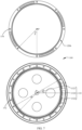
- the quantity of positioning members 152 is A; and the virtual rotation axis P of the decoration member 110 is used as a center of a circle, and an angle between two adjacent positioning members 152 is ⁇ .
- the quantity of induction members 154 is B; and the virtual rotation axis P of the decoration member 110 is used as a center of a circle, and an angle between two adjacent induction members 154 is ⁇ .
- a smaller angle of the angle ⁇ and the angle ⁇ may be understood as a preset angle.
- the induction member 154 on the dial plate 120 may directly face the positioning member 152 on the decoration member 110.
- the dial plate 120 may hover at a current position under magnetic forces of the induction member 154 and the positioning member 152, so that every time the dial plate 120 rotates by 15°, the dial plate may hover once.
- the dial plate 120 may be controlled to be in a hovering state.
- the external force may enable the dial plate 120 to rotate and be out of the hovering state, and the induction member 154 does not directly face the positioning member 152.
- the dial plate 120 still tends to return to the hovering state again.
- the dial plate 120 may automatically rotate and enable the induction member 154 to directly face the positioning member 152 again, and the dial plate 120 is in the hovering state again. Based on this, quick dialing and quick hovering of the dial plate 120 may be implemented, and the user's operation hand feeling may be improved.
- the positioning member 152 circumferentially surrounds the bearing portion 114 of the decoration member 110 as a whole, and the induction member 154 circumferentially surrounds the dial plate 120 as a whole.
- the quantity A of the positioning members 152 is 3 times the quantity B of the induction members 154.
- the quantity A of the positioning members 152 is 4 times the quantity B of the induction members 154.
- the positioning member 152 surrounds the bearing portion 114 of the decoration member 110 in an arc as a whole, and the induction member 154 circumferentially surrounds the dial plate 120 as a whole. It should be understood that, based on an arrangement manner of the arc, a certain region may be further reserved on the bearing portion 114, that is, the positioning member 152 is not disposed in this region, so as to facilitate arrangement of components such as a sensor.
- the angle ⁇ is 15°
- the arc is five sixths of a circumference (that is, an angle of the arc is 300°)
- the angle ⁇ is 45°.
- ⁇ ⁇ *3
- the angle ⁇ between adjacent positioning members 152 may be adaptively adjusted according to factors such as a size of the dial plate 120, design requirements, and rotation sensitivity of the dial plate 120, which is not limited.
- the camera decoration component 100 further includes a sliding member 160.
- the sliding member 160 may be sandwiched between the dial plate 120 and the bearing portion 114 of the decoration member 110 to support the dial plate 120 and improve the operation hand feeling when the dial plate 120 is dialed.
- the sliding member 160 may be disposed on the dial plate 120 or the bearing portion 114, and may be correspondingly disposed around the dial plate 120 or the bearing portion 114.
- the induction member 154 is made of magnetic iron
- the positioning member 152 is made of magnetic metal
- the quantity of the positioning members 152 is greater than the quantity of the induction members 154.
- the sliding member 160 may be disposed on the dial plate 120 and be spaced apart from the induction member 154.
- the dial plate 120 may be further provided with a slot 125, and the slot 125 is spaced apart from the second mounting groove 123. The sliding member 160 may partially extend into the slot 125 to mount the sliding member 160.
- the quantity of the sliding members 160 may be two or more.
- the quantity of the sliding members 160 is three, four, or five. It should be understood that, in some cases, under a magnetic force of the hovering mechanism 150, the user needs to exert a certain force to dial the dial plate 120, which may reduce the possibility that the dial plate 120 is dialed by mistake. Based on the cooperation between the hovering mechanism 150 and the sliding member 160, it can be ensured that the user has a relatively smooth and coherent dialing hand feeling when dialing the dial plate 120, so as to improve the user experience of dialing the dial plate 120.
- the sliding member 160 may be a spacer, for example, the sliding member 160 may be, but not limited to, a POM spacer.
- a surface of a sliding sheet may be further provided with a film layer such as a Teflon tape, to reduce a friction coefficient of the sliding sheet, prolong service life of the sliding sheet, and improve the operation hand feeling.
- the camera decoration component 100 may further include the Hall sensor 132, and the Hall sensor 132 may obtain related motion information of the dial plate 120 by sensing a change of the magnetic field.
- the induction member 154 is made of magnetic iron
- the positioning member 152 is made of magnetic metal.
- the Hall sensor 132 is correspondingly disposed on a side of the bearing portion 114 away from the dial plate 120, or the Hall sensor 132 may be correspondingly disposed on a side of the bearing portion 114 facing the dial plate 120.
- the positioning member 152 surrounds the bearing portion 114 of the decoration member 110 in an arc as a whole, while the Hall sensor 132 and the positioning member 152 may circumferentially surround the bearing portion 114 as a whole.
- the Hall sensor 132 may directly face the induction member 154 located on the dial plate 120.
- the dial plate 120 rotates and is out of the hovering state, the induction member 154 mounted on the dial plate 120 also synchronously rotates.
- the Hall sensor 132 uses the Hall sensor 132 as a reference to change a position of the induction member 154 directly facing the Hall sensor 132 changes; and based on a change of the position, the corresponding magnetic field information obtained by the Hall sensor 132 also changes. Based on this, the motion information of the dial plate 120 may be correspondingly obtained after a processor processes the magnetic field information. Therefore, when the dial plate 120 rotates, the Hall sensor 132 senses a change of the magnetic field, and information such as the rotation direction and the rotation angle of the dial plate 120 may be obtained to trigger a corresponding function of software.
- the Hall sensor 132 when the Hall sensor 132 is located on a side of the bearing portion 114 away from the dial plate 120, a part of the bearing portion 114 is disposed between the Hall sensor 132 and the induction member 154. However, because the part of the bearing portion 114 is not provided with the positioning member 152, the Hall sensor 132 may still relatively stably obtain the change of the magnetic field of the induction member 154 to obtain the motion information of the dial plate 120 and trigger the corresponding function of the software. Referring to FIG. 7 , in some embodiments, using the quantity of the Hall sensors 132 being more than one as an example for description, the plurality of Hall sensors 132 are sequentially disposed at intervals along the circumferential direction of the bearing portion 114.
- the virtual rotation axis P of the decoration member 110 is used as a center of a circle.
- the angle between the adj acent Hall sensors 132 and the angle between the Hall sensor 132 on the edge and the adjacent positioning member 152 are both ⁇ , and the angle ⁇ is the same as the angle ⁇ .
- the Hall sensor 132 may directly face the induction member 154; and whenever the dial plate 120 rotates, the magnetic field information of the induction member 154 is obtained by the Hall sensor 132, and the electronic device 10 may determine that the dial plate 120 rotates, so as to execute a corresponding program.
- the virtual rotation axis P of the decoration member 110 is used as a center of a circle.
- the processor may process the magnetic field information of the Hall sensor 132 to determine motion information such as a rotation direction and a rotation angle of the dial plate 120.
- the three Hall sensors 132 may be sequentially disposed at intervals along the circumferential direction of the bearing portion 114. It should be understood that, as shown in FIG.
- the Hall sensors 132 include a first Hall sensor 1321, a second Hall sensor 1322, and a third Hall sensor 1323.
- the dial plate 120 is initially in the hovering state, the first Hall sensor 1321 may directly face one induction member 154.
- the second Hall sensor 1322 may directly face the induction member 154.
- the third Hall sensor 1323 may directly face the induction member 154.
- the first Hall sensor 1321 may directly face another induction member 154, and at this point, the dial plate 120 stops rotating.
- the dial plate 120 stops rotating.
- a rotation direction of the dial plate 120 is the clockwise direction, and a total rotation angle of the dial plate 120 is 45°.
- motion information such as a rotation speed of the dial plate 120 may be further obtained. As shown in FIG.
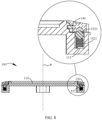
- the positioning member 152 may include an elastic member 1521 and a ball 1523, and the elastic member 1521 and the ball 1523 are sequentially disposed in the first mounting groove 113, where the elastic member 1521 is pressed between a groove bottom of the first mounting groove 113 and the ball 1523. Based on a force of the elastic member 1521 on the ball 1523, the ball 1523 may be pressed against the bottom surface 120b of the dial plate 120. By bouncing the ball 1523 between the second mounting grooves 123, the hovering of the dial plate 120 may also be implemented.
- the induction member 154 may be completely accommodated in the second mounting groove 123, so that the ball 1523 may be engaged with a notch of the second mounting groove 123, thereby implementing hovering.
- the ball 1523 is disengaged from the second mounting groove 123, and as the ball 1523 comes into contact with the bottom surface 120b of the dial plate 120, the ball 1523 also rolls along with the rotation of the dial plate 120, so that a mechanical sound of dialing the dial plate 120 is generated.
- the hovering mechanism 150 may alternatively not include the induction member 154, which may also implement functions such as rotation and hovering of the dial plate 120.
- the camera decoration component 100 may include a texture sensor 134. Similar to the Hall sensor 132 in FIG. 7 , the texture sensor 134 is correspondingly disposed on a side of the bearing portion 114 away from the dial plate 120, or the texture sensor 134 may be correspondingly disposed on a side of the bearing portion 114 facing the dial plate 120. It should be understood that the texture sensor 134 may obtain texture information of the bottom surface 120b of the dial plate 120 to determine motion information such as the rotation direction and the rotation angle of the dial plate 120. Because the texture sensor 134 and the Hall sensor 132 identify a rotation direction in different manners, aspects such as determining the rotation direction may be implemented by a texture sensor 134.
- a side of the dial plate 120 facing the bottom surface 120b is provided with an identification texture 122.
- the identification texture 122 may include grooves, protrusions, or the like, which are spaced apart along the circumferential direction of the dial plate 120.
- the groove or protrusion includes a certain inclination angle and depth, so that the texture sensor 134 may obtain related texture information.
- motion information such as the rotation direction and the rotation angle of the dial plate 120 may be determined.
- a thickness of the dial plate 120 may be further reduced, so as to implement lightening and thinning of the camera decoration component 100.
- the identification texture 122 being a groove is used as an example for description.
- the identification texture 122 being the groove may include a first surface 122a, a second surface 122b, and a third surface 122c, and the second surface 122b is connected between the first surface 122a and the third surface 122c.
- the inclination angle ⁇ and the inclination angle ⁇ are different in magnitude.
- the inclination angle ⁇ may be an obtuse angle
- the inclination angle ⁇ may be a right angle.
- texture information such as depth or roughness of the groove obtained by the texture sensor 134 is also different.
- the dial plate 120 rotates in a clockwise direction, the texture sensor 134 sequentially scans the first surface 122a, the second surface 122b, and the third surface 122c, and the processor may obtain first texture information through analysis; and the dial plate 120 rotates in a counterclockwise direction, the texture sensor 134 sequentially scans the third surface 122c, the second surface 122b, and the first surface 122a, and the processor may obtain second texture information through analysis.
- the first texture information and the second texture information are not the same based on differences in aspects such as the inclination angle ⁇ and the inclination angle ⁇ , scan time, and the like. Based on this, according to the texture information of the groove and intervals between the grooves, the rotation direction, the rotation angle, and the like of the dial plate 120 that is dialed may be determined, so as to facilitate execution of a related program.
- the first surface 122a may be a curved surface, and the third surface 122c may be a flat surface; or the first surface 122a may be a flat surface, and the third surface 122c may be a curved surface.
- the groove may include a first surface 122a and a second surface 122b, and there is an inclination angle between the first surface 122a and the second surface 122b; or the first surface 122a is a curved surface, and the second surface 122b is a flat surface; or the first surface 122a is a flat surface, and the second surface 122b is a curved surface; or the first surface 122a and the second surface 122b are curved surfaces with different curvatures.
- the corresponding texture information may also be obtained according to depth changes of the first surface 122a and the second surface 122b, and the motion information such as the rotation direction and the rotation angle of the dial plate 120 may also be determined according to the depth changes.
- the protrusion may be understood by analogy with the groove, for example, the protrusion may include a first surface, a second surface, and a third surface, and a convex top surface is connected between the first surface and the third surface, which is not repeated herein.
- the identification texture 122 may further include a plurality of groups of identification stripes with a gradual change in lengths, and the plurality of groups of identification stripes are disposed along the circumferential direction of the dial plate 120, where the length refers to a size of the identification stripe in a radial direction of the dial plate 120, and the gradual change may include gradual increase or gradual decrease
- the quantity of texture sensors 134 may be one, two, or more, which is not limited.
- a type of the texture sensor 134 may include a depth sensor, a laser sensor, or the like.
- the identification texture 122 may be formed on the dial plate 120 by a process such as CNC or laser engraving.
- the embodiments of this application further provide a camera module, and the camera module may include a camera and the camera decoration component 100 described in the foregoing embodiments.
- a through hole of the decoration member 110 may directly face a lens of the camera, so that an image sensor of the camera may obtain external light or reflected light.
- the electronic device 10 may quickly enter a one-handed operation mode by dialing the dial plate 120 in one direction. Commonly used applications may be placed close to a corner of a screen to help the user perform the one-handed operation.
- the dial plate 120 may be dialed in an opposite direction to switch the electronic device 10 from the one-handed operation mode to a normal mode.
- quick switching between the normal mode and the one-handed operation mode may be implemented to meet the user's use requirement.
- the user may dial the dial plate 120 with an index finger of the right hand, generally dial the dial plate 120 in a counterclockwise direction.
- the electronic device 10 may enter the one-handed operation mode, and commonly used applications are located in a region in a lower right corner of the screen, so that the user's right thumb may easily touch.
- the dial plate 120 is generally dialed clockwise, which may be understood by analogy with the foregoing example, and is not repeated herein.
- the user when the camera decoration component 100 is applied to the electronic device 10, and when performing an operation such as video recording or photographing, the user may zoom a video or an image or rapidly switch between modes such as a video recording mode and a photographing mode by dialing the dial plate 120. It should be understood that, based on a preset angle of the dial plate 120, the user may relatively accurately zoom the video or image, or rapidly switch between the video recording mode and the photographing mode, so as to improve the user experience.
- an image may be zoomed in or out, that is, an imaging focal length of the camera module may be changed.
- the focal length is reduced; and when the dial plate 120 is dialed in a counterclockwise direction, the focal length is increased.
- the dial plate 120 when the camera decoration component 100 is applied to the electronic device 10, and when the user watches a video in a landscape orientation, by dialing the dial plate 120, functions such as fast forwarding and fast rewinding may be implemented. It should be understood that, based on the rotation direction and the rotation angle of the dial plate 120, extents of fast forwarding and fast rewinding may be precisely controlled to meet the watching requirements of the user.
- some customized functions may be correspondingly expanded based on the dial plate 120. For example, by dialing the dial plate 120, it is possible to zoom in or out, switch a perspective, switch an application (APP), view a pop-up message, or the like.
- APP application
- the user may further implement functions such as controlling volume increase and decrease, flipping a video or a picture, zooming in and out an image or a text, and switching applications in special scenarios.
Landscapes
- Engineering & Computer Science (AREA)
- Signal Processing (AREA)
- Telephone Set Structure (AREA)
- Studio Devices (AREA)
Claims (14)
- Elektronische Vorrichtung (10), umfassend eine hintere Abdeckung (16) und eine Kameradekorationskomponente (100), die fest verbunden sind, wobeidie Kameradekorationskomponente (100) ein Dekorationselement (110), eine Wählscheibe (120), eine Vielzahl von Positionierungselementen (152) und eine Vielzahl von Induktionselementen (154) umfasst; die Wählscheibe (120) ringförmig ist und auf einer äußeren Umfangsseite des Dekorationselements (110) aufgebracht ist; das Dekorationselement (110) eine virtuelle Drehachse (P) umfasst und die Wählscheibe (120) mit dem Dekorationselement (110) drehbar verbunden ist und konfiguriert ist, um sich um die virtuelle Drehachse (P) des Dekorationselements (110) herum zu drehen;die Vielzahl von Positionierungselementen (152) an dem Dekorationselement (110) befestigt ist und in Richtung der Wählscheibe (120) angeordnet ist, die Vielzahl von Positionierungselementen (152) in gleichen Abständen entlang einer Umfangsrichtung der virtuellen Drehachse (P) angeordnet ist, die Vielzahl von Induktionselementen (154) an der Wählscheibe (120) befestigt ist und in Richtung des Dekorationselements (110) angeordnet ist, und die Vielzahl von Induktionselementen (154) in gleichen Abständen entlang der Umfangsrichtung der virtuellen Drehachse (P) angeordnet ist;die virtuelle Drehachse (P) als Mittelpunkt eines Kreises verwendet wird, ein Winkel zwischen zwei benachbarten Positionierungselementen (152) α ist, ein Winkel zwischen zwei benachbarten Induktionselementen (154) β ist und zwischen dem Winkel α und dem Winkel β eine Beziehung eines ganzzahligen Vielfachen besteht; und während sie einander direkt zugewandt sind, das Positionierungselement (152) und das Induktionselement (154) konfiguriert sind, um die Wählscheibe (120) zu steuern, um in einem Schwebezustand zu sein, wobei die Vielzahl von Induktionselementen (154) aus magnetischem Eisen hergestellt ist, und die Vielzahl von Positionierungselementen (152) aus magnetischem Metall oder magnetischem Eisen hergestellt ist; oder die Vielzahl von Induktionselementen (154) aus magnetischem Metall hergestellt ist und die Vielzahl von Positionierungselementen (152) aus magnetischem Eisen hergestellt ist.
- Elektronische Vorrichtung (10) nach Anspruch 1, wobei die elektronische Vorrichtung (10) ferner einen Sensor (132, 134) umfasst und der Sensor (132, 134) der Wählscheibe (120) direkt zugewandt ist und konfiguriert ist, um Bewegungsinformationen der Wählscheibe (120) während einer Drehung zu erhalten.
- Elektronische Vorrichtung (10) nach Anspruch 1 oder 2, wobei das Dekorationselement (110) einen Hauptkörperabschnitt (112) und einen ringförmigen Lagerabschnitt (114) umfasst und sich der Lagerabschnitt (114) auf einer Außenseite des Hauptkörperabschnitts (112) befindet und um den Hauptkörperabschnitt (112) herum angeordnet ist; und die Vielzahl von Positionierungselementen (152) in gleichen Abständen entlang einer Umfangsrichtung des Lagerabschnitts (114) angeordnet ist.
- Elektronische Vorrichtung (10) nach Anspruch 3, wobei der Lagerabschnitt (114) eine Vielzahl von ersten Montagenuten (113) umfasst, die in gleichen Abständen angeordnet sind, und jedes der Positionierungselemente (152) entsprechend in jeder der ersten Montagenuten (113) montiert ist; und die Wählscheibe (120) auf dem Lagerabschnitt (114) angeordnet ist und mit dem Hauptkörperabschnitt (112) drehbar verbunden ist, wobei die Wählscheibe (120) eine Vielzahl von zweiten Montagenuten (123) umfasst, die in gleichen Abständen angeordnet sind, und jedes der Induktionselemente (154) entsprechend in jeder der zweiten Montagenuten (123) montiert ist.
- Elektronische Vorrichtung (10) nach Anspruch 3 oder 4, wobei der Hauptkörperabschnitt (112) mit einem Buckel (116) in einer axialen Richtung entlang der virtuellen Drehachse (P) versehen ist und der Buckel (116) relativ zu der Wählscheibe (120) vorsteht.
- Elektronische Vorrichtung (10) nach einem der Ansprüche 3 bis 5, wobei das Positionierungselement (152) aus magnetischem Metall hergestellt ist, das Induktionselement (154) aus magnetischem Eisen hergestellt ist und der Sensor (132, 134) ein Hall-Sensor (132); und
in einem Fall, dass die Wählscheibe (120) in dem Schwebezustand ist, der Hall-Sensor (132) dem Induktionselement (154) direkt zugewandt ist und der Hall-Sensor (132) konfiguriert ist, um Informationen über eine Magnetfeldänderung des Induktionselements (154) zu erhalten, das sich während der Bewegung der Wählscheibe (120) synchron bewegt. - Elektronische Vorrichtung (10) nach Anspruch 6, wobei eine Beziehung zwischen dem Winkel α und dem Winkel β α=β*N ist, wobei N eine positive ganze Zahl größer als oder gleich 3 ist;die Anzahl der Hall-Sensoren (132) N ist und die Vielzahl von Positionierungselementen (152) und die N Hall-Sensoren (132) insgesamt um den Lagerabschnitt (114) herum angeordnet sind, wobeidie virtuelle Drehachse (P) als Mittelpunkt des Kreises verwendet wird, sowohl ein Winkel zwischen zwei benachbarten Hall-Sensoren (132) als auch ein Winkel zwischen einem Hall-Sensor (132) und einem benachbarten Positionierungselement (152) λ sind, und λ=β.
- Elektronische Vorrichtung (10) nach einem der Ansprüche 3 bis 5, wobei die Wählscheibe (120) eine obere Oberfläche (120a) und eine untere Oberfläche (120b) aufweist, die einander gegenüberliegen, und die untere Oberfläche (120b) dem Lagerabschnitt (114) zugewandt ist;
eine Seite der Wählscheibe (120), die der unteren Oberfläche (120b) zugewandt ist, mit einer Identifikationstextur (122) versehen ist; und der Sensor (132, 134) ein Textursensor (134) ist und der Textursensor (134) konfiguriert ist, um Texturinformationen der Identifikationstextur (122) zu erhalten, die sich während der Bewegung der Wählscheibe (120) synchron bewegt. - Elektronische Vorrichtung (10) nach Anspruch 8, wobei die Identifikationstextur (122) eine Vielzahl von Nuten oder eine Vielzahl von Vorsprüngen umfasst und die Vielzahl von Nuten oder die Vielzahl von Vorsprüngen in gleichen Abständen entlang der Umfangsrichtung der virtuellen Drehachse (P) angeordnet sind.
- Elektronische Vorrichtung (10) nach Anspruch 9, wobei jede der Nuten oder jeder der Vorsprünge eine erste Oberfläche (122a), eine zweite Oberfläche (122b) und eine dritte Oberfläche (122c) umfasst, die nacheinander verbunden sind; und es einen Neigungswinkel θ zwischen der ersten Oberfläche (122a) und der zweiten Oberfläche (122b) gibt, es einen Neigungswinkel ϕ zwischen der zweiten Oberfläche (122b) und der dritten Oberfläche (122c) gibt und der Neigungswinkel θ und der Neigungswinkel ϕ unterschiedlich groß sind.
- Elektronische Vorrichtung (10) nach einem der Ansprüche 1 bis 10, wobei die Kameradekorationskomponente (100) ferner ein Gleitelement (160) umfasst und das Gleitelement (160) zwischen der Wählscheibe (120) und dem Lagerabschnitt (114) eingeschoben ist und von dem Positionierungselement (152) beanstandet ist.
- Elektronische Vorrichtung (10) nach einem der Ansprüche 1 bis 5 oder 11, wobei das Dekorationselement (110) eine erste Nut (111) umfasst, die entlang der Umfangsrichtung der virtuellen Drehachse (P) angeordnet ist, die Wählscheibe (120) eine zweite Nut (121) umfasst, die entlang der Umfangsrichtung der virtuellen Drehachse (P) angeordnet ist, und die zweite Nut (121) der ersten Nut (111) direkt zugewandt ist; und
die Kameradekorationskomponente (100) ferner eine Dichtung (140) umfasst; und die Dichtung (140) zwischen der ersten Nut (111) und der zweiten Nut (121) eingeschoben ist und konfiguriert ist, um eine drehbare Verbindung zwischen der Wählscheibe (120) und dem Dekorationselement (110) zu implementieren. - Elektronische Vorrichtung (10) nach Anspruch 12, wobei die Dichtung (140) einen ringförmigen Abschnitt (142), einen ersten Knickabschnitt (144) und einen zweiten Knickabschnitt (146) umfasst; und sich der erste Knickabschnitt (144) auf einer Innenseite des ringförmigen Abschnitts (142) befindet und sich der zweite Knickabschnitt (146) auf einer Außenseite des ringförmigen Abschnitts (142) befindet und abwechselnd mit dem ersten Knickabschnitt (144) angeordnet ist, wobei der erste Knickabschnitt (144) mindestens teilweise in der ersten Nut (111) angeordnet ist und der zweite Knickabschnitt (146) mindestens teilweise in der zweiten Nut (121) angeordnet ist.
- Elektronische Vorrichtung (10) nach Anspruch 4, wobei das Positionierungselement (152) ein elastisches Element (1521) und eine Kugel (1523) umfasst, das elastische Element (1521) und die Kugel (1523) nacheinander in der ersten Montagenut (113) angeordnet sind, und das elastische Element (1521) zwischen dem Lagerabschnitt (114) und der Kugel (1523) gepresst wird, wobei in einem Fall, dass die Kugel (1523) mit der zweiten Montagenut (123) in Eingriff steht, die Wählscheibe (120) gesteuert wird, um in dem Schwebezustand zu sein.
Applications Claiming Priority (3)
| Application Number | Priority Date | Filing Date | Title |
|---|---|---|---|
| CN202110237840 | 2021-03-03 | ||
| CN202110595681.0A CN115022441B (zh) | 2021-03-03 | 2021-05-29 | 电子设备 |
| PCT/CN2022/078629 WO2022184057A1 (zh) | 2021-03-03 | 2022-03-01 | 电子设备 |
Publications (3)
| Publication Number | Publication Date |
|---|---|
| EP4080860A1 EP4080860A1 (de) | 2022-10-26 |
| EP4080860A4 EP4080860A4 (de) | 2023-07-26 |
| EP4080860B1 true EP4080860B1 (de) | 2024-05-01 |
Family
ID=83064559
Family Applications (1)
| Application Number | Title | Priority Date | Filing Date |
|---|---|---|---|
| EP22732886.1A Active EP4080860B1 (de) | 2021-03-03 | 2022-03-01 | Elektronische vorrichtung |
Country Status (4)
| Country | Link |
|---|---|
| US (1) | US12244751B2 (de) |
| EP (1) | EP4080860B1 (de) |
| CN (1) | CN115022441B (de) |
| WO (1) | WO2022184057A1 (de) |
Families Citing this family (4)
| Publication number | Priority date | Publication date | Assignee | Title |
|---|---|---|---|---|
| EP4391503B1 (de) | 2022-10-24 | 2025-10-01 | Honor Device Co., Ltd. | Elektronische vorrichtung |
| CN115604556B (zh) * | 2022-12-01 | 2023-09-05 | 荣耀终端有限公司 | 摄像头装饰组件及电子设备 |
| CN119967072A (zh) * | 2023-10-31 | 2025-05-09 | 荣耀终端股份有限公司 | 一种移动终端及移动终端的交互方法 |
| CN118381844A (zh) * | 2024-04-15 | 2024-07-23 | Oppo广东移动通信有限公司 | 电子设备和电子设备系统 |
Family Cites Families (16)
| Publication number | Priority date | Publication date | Assignee | Title |
|---|---|---|---|---|
| JP3820548B2 (ja) * | 2001-06-01 | 2006-09-13 | ソニー株式会社 | 情報入力装置とそれを用いた電子機器 |
| KR20070078443A (ko) * | 2006-01-27 | 2007-08-01 | 주식회사 팬택 | 다이얼 휠을 구비하는 이동통신단말기 |
| JP2008078045A (ja) * | 2006-09-22 | 2008-04-03 | Olympus Corp | ダイヤルスイッチ、電子機器およびカメラ |
| CN201285488Y (zh) * | 2008-10-22 | 2009-08-05 | 华晶科技股份有限公司 | 转盘模块 |
| CN201311537Y (zh) * | 2008-11-17 | 2009-09-16 | 华晶科技股份有限公司 | 转盘模块及具该转盘模块的切换机构 |
| CN201421795Y (zh) * | 2009-01-19 | 2010-03-10 | 华晶科技股份有限公司 | 电子装置的模式转盘机构 |
| JP5896662B2 (ja) * | 2011-09-15 | 2016-03-30 | キヤノン株式会社 | 撮像装置及びアクセサリ |
| CN202841274U (zh) * | 2012-09-24 | 2013-03-27 | 广东欧珀移动通信有限公司 | 手机 |
| KR102313898B1 (ko) * | 2015-02-27 | 2021-10-19 | 삼성전자주식회사 | 웨어러블 전자장치 |
| US10345123B2 (en) * | 2015-07-04 | 2019-07-09 | Push, Inc. | Water resistant smart gauge |
| JP7059607B2 (ja) * | 2017-12-11 | 2022-04-26 | セイコーエプソン株式会社 | 回転ベゼル付時計 |
| CN108174070A (zh) * | 2018-01-10 | 2018-06-15 | 京东方科技集团股份有限公司 | 摄像头模块及具有该摄像头模块的移动设备 |
| EP3543798B1 (de) * | 2018-03-20 | 2020-12-30 | Omega SA | System eines drehbaren aussenrings einer armbanduhr, das mit mindestens einem federnden arm ausgestattet ist |
| US11787050B1 (en) * | 2019-01-01 | 2023-10-17 | Sanctuary Cognitive Systems Corporation | Artificial intelligence-actuated robot |
| CN111327832A (zh) * | 2020-03-31 | 2020-06-23 | 厦门美图之家科技有限公司 | 拍照参数调节方法、装置、电子设备和可读存储介质 |
| CN212572639U (zh) * | 2020-08-31 | 2021-02-19 | 维沃移动通信有限公司 | 电子设备 |
-
2021
- 2021-05-29 CN CN202110595681.0A patent/CN115022441B/zh active Active
-
2022
- 2022-03-01 US US17/790,338 patent/US12244751B2/en active Active
- 2022-03-01 WO PCT/CN2022/078629 patent/WO2022184057A1/zh not_active Ceased
- 2022-03-01 EP EP22732886.1A patent/EP4080860B1/de active Active
Also Published As
| Publication number | Publication date |
|---|---|
| US12244751B2 (en) | 2025-03-04 |
| EP4080860A1 (de) | 2022-10-26 |
| EP4080860A4 (de) | 2023-07-26 |
| WO2022184057A1 (zh) | 2022-09-09 |
| US20240195902A1 (en) | 2024-06-13 |
| CN115022441B (zh) | 2023-08-25 |
| CN115022441A (zh) | 2022-09-06 |
Similar Documents
| Publication | Publication Date | Title |
|---|---|---|
| US12244751B2 (en) | Electronic device | |
| JP3671883B2 (ja) | 画像記録再生装置 | |
| JP4649134B2 (ja) | 電子機器 | |
| US7239304B2 (en) | Pointing device and portable information terminal using the same | |
| EP3335409B1 (de) | Tragbare vorrichtung und verfahren zur steuerung eines bildschirms davon | |
| EP2463712B1 (de) | Elektronische Vorrichtung, die unterschiedliche Arten von Betriebsabläufen auf Drehbetriebselementen erkennt | |
| US20020093492A1 (en) | System for a navigable display | |
| WO2003091867A1 (en) | Graphical user interface and method and electronic device for navigating in the graphical user interface | |
| US11012625B2 (en) | Electronic equipment having a touch operating face | |
| JP2010092086A (ja) | ユーザ入力装置、デジタルカメラ、入力制御方法、および入力制御プログラム | |
| KR20220074989A (ko) | 측벽 디스플레이를 갖는 전자 디바이스 | |
| US9251977B2 (en) | Electronic apparatus | |
| HK40078689B (zh) | 电子设备 | |
| HK40078689A (en) | Electronic device | |
| JP6078861B2 (ja) | 触感切替スイッチを有するデジタルカメラ | |
| JP6676807B2 (ja) | 電子機器 | |
| US20200004360A1 (en) | Electronic equipment | |
| JP2017003996A6 (ja) | 触感切替スイッチを有するデジタルカメラ | |
| JPWO2013073197A1 (ja) | 撮像装置及び撮像制御プログラム | |
| JP2011187168A (ja) | 操作スイッチおよび携帯端末 | |
| JPH08255052A (ja) | 座標入力装置及び方法 | |
| JP6133016B2 (ja) | 入力装置及びそれを有する電子機器 | |
| JPH06301481A (ja) | 3次元入力装置 | |
| JP5440284B2 (ja) | アナログポインティングキー構造 | |
| JP2014225381A (ja) | 回転ダイヤルおよび電子機器 |
Legal Events
| Date | Code | Title | Description |
|---|---|---|---|
| STAA | Information on the status of an ep patent application or granted ep patent |
Free format text: STATUS: UNKNOWN |
|
| STAA | Information on the status of an ep patent application or granted ep patent |
Free format text: STATUS: THE INTERNATIONAL PUBLICATION HAS BEEN MADE |
|
| PUAI | Public reference made under article 153(3) epc to a published international application that has entered the european phase |
Free format text: ORIGINAL CODE: 0009012 |
|
| STAA | Information on the status of an ep patent application or granted ep patent |
Free format text: STATUS: REQUEST FOR EXAMINATION WAS MADE |
|
| 17P | Request for examination filed |
Effective date: 20220701 |
|
| AK | Designated contracting states |
Kind code of ref document: A1 Designated state(s): AL AT BE BG CH CY CZ DE DK EE ES FI FR GB GR HR HU IE IS IT LI LT LU LV MC MK MT NL NO PL PT RO RS SE SI SK SM TR |
|
| A4 | Supplementary search report drawn up and despatched |
Effective date: 20230627 |
|
| RIC1 | Information provided on ipc code assigned before grant |
Ipc: H04M 1/02 20060101ALI20230621BHEP Ipc: H04M 1/23 20060101AFI20230621BHEP |
|
| GRAP | Despatch of communication of intention to grant a patent |
Free format text: ORIGINAL CODE: EPIDOSNIGR1 |
|
| STAA | Information on the status of an ep patent application or granted ep patent |
Free format text: STATUS: GRANT OF PATENT IS INTENDED |
|
| INTG | Intention to grant announced |
Effective date: 20231212 |
|
| GRAS | Grant fee paid |
Free format text: ORIGINAL CODE: EPIDOSNIGR3 |
|
| GRAA | (expected) grant |
Free format text: ORIGINAL CODE: 0009210 |
|
| STAA | Information on the status of an ep patent application or granted ep patent |
Free format text: STATUS: THE PATENT HAS BEEN GRANTED |
|
| AK | Designated contracting states |
Kind code of ref document: B1 Designated state(s): AL AT BE BG CH CY CZ DE DK EE ES FI FR GB GR HR HU IE IS IT LI LT LU LV MC MK MT NL NO PL PT RO RS SE SI SK SM TR |
|
| DAV | Request for validation of the european patent (deleted) | ||
| DAX | Request for extension of the european patent (deleted) | ||
| REG | Reference to a national code |
Ref country code: GB Ref legal event code: FG4D |
|
| REG | Reference to a national code |
Ref country code: CH Ref legal event code: EP |
|
| REG | Reference to a national code |
Ref country code: DE Ref legal event code: R096 Ref document number: 602022003249 Country of ref document: DE |
|
| REG | Reference to a national code |
Ref country code: IE Ref legal event code: FG4D |
|
| REG | Reference to a national code |
Ref country code: NL Ref legal event code: FP |
|
| REG | Reference to a national code |
Ref country code: LT Ref legal event code: MG9D |
|
| PG25 | Lapsed in a contracting state [announced via postgrant information from national office to epo] |
Ref country code: IS Free format text: LAPSE BECAUSE OF FAILURE TO SUBMIT A TRANSLATION OF THE DESCRIPTION OR TO PAY THE FEE WITHIN THE PRESCRIBED TIME-LIMIT Effective date: 20240901 |
|
| PG25 | Lapsed in a contracting state [announced via postgrant information from national office to epo] |
Ref country code: BG Free format text: LAPSE BECAUSE OF FAILURE TO SUBMIT A TRANSLATION OF THE DESCRIPTION OR TO PAY THE FEE WITHIN THE PRESCRIBED TIME-LIMIT Effective date: 20240501 |
|
| PG25 | Lapsed in a contracting state [announced via postgrant information from national office to epo] |
Ref country code: FI Free format text: LAPSE BECAUSE OF FAILURE TO SUBMIT A TRANSLATION OF THE DESCRIPTION OR TO PAY THE FEE WITHIN THE PRESCRIBED TIME-LIMIT Effective date: 20240501 Ref country code: HR Free format text: LAPSE BECAUSE OF FAILURE TO SUBMIT A TRANSLATION OF THE DESCRIPTION OR TO PAY THE FEE WITHIN THE PRESCRIBED TIME-LIMIT Effective date: 20240501 |
|
| PG25 | Lapsed in a contracting state [announced via postgrant information from national office to epo] |
Ref country code: GR Free format text: LAPSE BECAUSE OF FAILURE TO SUBMIT A TRANSLATION OF THE DESCRIPTION OR TO PAY THE FEE WITHIN THE PRESCRIBED TIME-LIMIT Effective date: 20240802 |
|
| PG25 | Lapsed in a contracting state [announced via postgrant information from national office to epo] |
Ref country code: PT Free format text: LAPSE BECAUSE OF FAILURE TO SUBMIT A TRANSLATION OF THE DESCRIPTION OR TO PAY THE FEE WITHIN THE PRESCRIBED TIME-LIMIT Effective date: 20240902 |
|
| REG | Reference to a national code |
Ref country code: AT Ref legal event code: MK05 Ref document number: 1683942 Country of ref document: AT Kind code of ref document: T Effective date: 20240501 |
|
| PG25 | Lapsed in a contracting state [announced via postgrant information from national office to epo] |
Ref country code: ES Free format text: LAPSE BECAUSE OF FAILURE TO SUBMIT A TRANSLATION OF THE DESCRIPTION OR TO PAY THE FEE WITHIN THE PRESCRIBED TIME-LIMIT Effective date: 20240501 |
|
| PG25 | Lapsed in a contracting state [announced via postgrant information from national office to epo] |
Ref country code: AT Free format text: LAPSE BECAUSE OF FAILURE TO SUBMIT A TRANSLATION OF THE DESCRIPTION OR TO PAY THE FEE WITHIN THE PRESCRIBED TIME-LIMIT Effective date: 20240501 |
|
| PG25 | Lapsed in a contracting state [announced via postgrant information from national office to epo] |
Ref country code: PL Free format text: LAPSE BECAUSE OF FAILURE TO SUBMIT A TRANSLATION OF THE DESCRIPTION OR TO PAY THE FEE WITHIN THE PRESCRIBED TIME-LIMIT Effective date: 20240501 |
|
| PG25 | Lapsed in a contracting state [announced via postgrant information from national office to epo] |
Ref country code: LV Free format text: LAPSE BECAUSE OF FAILURE TO SUBMIT A TRANSLATION OF THE DESCRIPTION OR TO PAY THE FEE WITHIN THE PRESCRIBED TIME-LIMIT Effective date: 20240501 |
|
| PG25 | Lapsed in a contracting state [announced via postgrant information from national office to epo] |
Ref country code: PT Free format text: LAPSE BECAUSE OF FAILURE TO SUBMIT A TRANSLATION OF THE DESCRIPTION OR TO PAY THE FEE WITHIN THE PRESCRIBED TIME-LIMIT Effective date: 20240902 Ref country code: PL Free format text: LAPSE BECAUSE OF FAILURE TO SUBMIT A TRANSLATION OF THE DESCRIPTION OR TO PAY THE FEE WITHIN THE PRESCRIBED TIME-LIMIT Effective date: 20240501 Ref country code: NO Free format text: LAPSE BECAUSE OF FAILURE TO SUBMIT A TRANSLATION OF THE DESCRIPTION OR TO PAY THE FEE WITHIN THE PRESCRIBED TIME-LIMIT Effective date: 20240801 Ref country code: LV Free format text: LAPSE BECAUSE OF FAILURE TO SUBMIT A TRANSLATION OF THE DESCRIPTION OR TO PAY THE FEE WITHIN THE PRESCRIBED TIME-LIMIT Effective date: 20240501 Ref country code: IS Free format text: LAPSE BECAUSE OF FAILURE TO SUBMIT A TRANSLATION OF THE DESCRIPTION OR TO PAY THE FEE WITHIN THE PRESCRIBED TIME-LIMIT Effective date: 20240901 Ref country code: HR Free format text: LAPSE BECAUSE OF FAILURE TO SUBMIT A TRANSLATION OF THE DESCRIPTION OR TO PAY THE FEE WITHIN THE PRESCRIBED TIME-LIMIT Effective date: 20240501 Ref country code: GR Free format text: LAPSE BECAUSE OF FAILURE TO SUBMIT A TRANSLATION OF THE DESCRIPTION OR TO PAY THE FEE WITHIN THE PRESCRIBED TIME-LIMIT Effective date: 20240802 Ref country code: FI Free format text: LAPSE BECAUSE OF FAILURE TO SUBMIT A TRANSLATION OF THE DESCRIPTION OR TO PAY THE FEE WITHIN THE PRESCRIBED TIME-LIMIT Effective date: 20240501 Ref country code: ES Free format text: LAPSE BECAUSE OF FAILURE TO SUBMIT A TRANSLATION OF THE DESCRIPTION OR TO PAY THE FEE WITHIN THE PRESCRIBED TIME-LIMIT Effective date: 20240501 Ref country code: BG Free format text: LAPSE BECAUSE OF FAILURE TO SUBMIT A TRANSLATION OF THE DESCRIPTION OR TO PAY THE FEE WITHIN THE PRESCRIBED TIME-LIMIT Effective date: 20240501 Ref country code: AT Free format text: LAPSE BECAUSE OF FAILURE TO SUBMIT A TRANSLATION OF THE DESCRIPTION OR TO PAY THE FEE WITHIN THE PRESCRIBED TIME-LIMIT Effective date: 20240501 Ref country code: RS Free format text: LAPSE BECAUSE OF FAILURE TO SUBMIT A TRANSLATION OF THE DESCRIPTION OR TO PAY THE FEE WITHIN THE PRESCRIBED TIME-LIMIT Effective date: 20240801 |
|
| PG25 | Lapsed in a contracting state [announced via postgrant information from national office to epo] |
Ref country code: DK Free format text: LAPSE BECAUSE OF FAILURE TO SUBMIT A TRANSLATION OF THE DESCRIPTION OR TO PAY THE FEE WITHIN THE PRESCRIBED TIME-LIMIT Effective date: 20240501 |
|
| PG25 | Lapsed in a contracting state [announced via postgrant information from national office to epo] |
Ref country code: EE Free format text: LAPSE BECAUSE OF FAILURE TO SUBMIT A TRANSLATION OF THE DESCRIPTION OR TO PAY THE FEE WITHIN THE PRESCRIBED TIME-LIMIT Effective date: 20240501 |
|
| PG25 | Lapsed in a contracting state [announced via postgrant information from national office to epo] |
Ref country code: CZ Free format text: LAPSE BECAUSE OF FAILURE TO SUBMIT A TRANSLATION OF THE DESCRIPTION OR TO PAY THE FEE WITHIN THE PRESCRIBED TIME-LIMIT Effective date: 20240501 |
|
| PG25 | Lapsed in a contracting state [announced via postgrant information from national office to epo] |
Ref country code: SK Free format text: LAPSE BECAUSE OF FAILURE TO SUBMIT A TRANSLATION OF THE DESCRIPTION OR TO PAY THE FEE WITHIN THE PRESCRIBED TIME-LIMIT Effective date: 20240501 Ref country code: RO Free format text: LAPSE BECAUSE OF FAILURE TO SUBMIT A TRANSLATION OF THE DESCRIPTION OR TO PAY THE FEE WITHIN THE PRESCRIBED TIME-LIMIT Effective date: 20240501 |
|
| PG25 | Lapsed in a contracting state [announced via postgrant information from national office to epo] |
Ref country code: SM Free format text: LAPSE BECAUSE OF FAILURE TO SUBMIT A TRANSLATION OF THE DESCRIPTION OR TO PAY THE FEE WITHIN THE PRESCRIBED TIME-LIMIT Effective date: 20240501 |
|
| PG25 | Lapsed in a contracting state [announced via postgrant information from national office to epo] |
Ref country code: SM Free format text: LAPSE BECAUSE OF FAILURE TO SUBMIT A TRANSLATION OF THE DESCRIPTION OR TO PAY THE FEE WITHIN THE PRESCRIBED TIME-LIMIT Effective date: 20240501 Ref country code: SK Free format text: LAPSE BECAUSE OF FAILURE TO SUBMIT A TRANSLATION OF THE DESCRIPTION OR TO PAY THE FEE WITHIN THE PRESCRIBED TIME-LIMIT Effective date: 20240501 Ref country code: RO Free format text: LAPSE BECAUSE OF FAILURE TO SUBMIT A TRANSLATION OF THE DESCRIPTION OR TO PAY THE FEE WITHIN THE PRESCRIBED TIME-LIMIT Effective date: 20240501 Ref country code: EE Free format text: LAPSE BECAUSE OF FAILURE TO SUBMIT A TRANSLATION OF THE DESCRIPTION OR TO PAY THE FEE WITHIN THE PRESCRIBED TIME-LIMIT Effective date: 20240501 Ref country code: DK Free format text: LAPSE BECAUSE OF FAILURE TO SUBMIT A TRANSLATION OF THE DESCRIPTION OR TO PAY THE FEE WITHIN THE PRESCRIBED TIME-LIMIT Effective date: 20240501 Ref country code: CZ Free format text: LAPSE BECAUSE OF FAILURE TO SUBMIT A TRANSLATION OF THE DESCRIPTION OR TO PAY THE FEE WITHIN THE PRESCRIBED TIME-LIMIT Effective date: 20240501 |
|
| REG | Reference to a national code |
Ref country code: DE Ref legal event code: R097 Ref document number: 602022003249 Country of ref document: DE |
|
| PG25 | Lapsed in a contracting state [announced via postgrant information from national office to epo] |
Ref country code: IT Free format text: LAPSE BECAUSE OF FAILURE TO SUBMIT A TRANSLATION OF THE DESCRIPTION OR TO PAY THE FEE WITHIN THE PRESCRIBED TIME-LIMIT Effective date: 20240501 |
|
| PLBE | No opposition filed within time limit |
Free format text: ORIGINAL CODE: 0009261 |
|
| STAA | Information on the status of an ep patent application or granted ep patent |
Free format text: STATUS: NO OPPOSITION FILED WITHIN TIME LIMIT |
|
| 26N | No opposition filed |
Effective date: 20250204 |
|
| PG25 | Lapsed in a contracting state [announced via postgrant information from national office to epo] |
Ref country code: SI Free format text: LAPSE BECAUSE OF FAILURE TO SUBMIT A TRANSLATION OF THE DESCRIPTION OR TO PAY THE FEE WITHIN THE PRESCRIBED TIME-LIMIT Effective date: 20240501 |
|
| PG25 | Lapsed in a contracting state [announced via postgrant information from national office to epo] |
Ref country code: SE Free format text: LAPSE BECAUSE OF FAILURE TO SUBMIT A TRANSLATION OF THE DESCRIPTION OR TO PAY THE FEE WITHIN THE PRESCRIBED TIME-LIMIT Effective date: 20240501 |
|
| PG25 | Lapsed in a contracting state [announced via postgrant information from national office to epo] |
Ref country code: MC Free format text: LAPSE BECAUSE OF FAILURE TO SUBMIT A TRANSLATION OF THE DESCRIPTION OR TO PAY THE FEE WITHIN THE PRESCRIBED TIME-LIMIT Effective date: 20240501 |
|
| REG | Reference to a national code |
Ref country code: CH Ref legal event code: H13 Free format text: ST27 STATUS EVENT CODE: U-0-0-H10-H13 (AS PROVIDED BY THE NATIONAL OFFICE) Effective date: 20251024 |
|
| PG25 | Lapsed in a contracting state [announced via postgrant information from national office to epo] |
Ref country code: LU Free format text: LAPSE BECAUSE OF NON-PAYMENT OF DUE FEES Effective date: 20250301 |
|
| REG | Reference to a national code |
Ref country code: BE Ref legal event code: MM Effective date: 20250331 |
|
| PG25 | Lapsed in a contracting state [announced via postgrant information from national office to epo] |
Ref country code: FR Free format text: LAPSE BECAUSE OF NON-PAYMENT OF DUE FEES Effective date: 20250331 |
|
| PG25 | Lapsed in a contracting state [announced via postgrant information from national office to epo] |
Ref country code: BE Free format text: LAPSE BECAUSE OF NON-PAYMENT OF DUE FEES Effective date: 20250331 |
|
| PG25 | Lapsed in a contracting state [announced via postgrant information from national office to epo] |
Ref country code: CH Free format text: LAPSE BECAUSE OF NON-PAYMENT OF DUE FEES Effective date: 20250331 |
|
| PG25 | Lapsed in a contracting state [announced via postgrant information from national office to epo] |
Ref country code: IE Free format text: LAPSE BECAUSE OF NON-PAYMENT OF DUE FEES Effective date: 20250301 |
|
| PGFP | Annual fee paid to national office [announced via postgrant information from national office to epo] |
Ref country code: NL Payment date: 20260213 Year of fee payment: 5 |
|
| PGFP | Annual fee paid to national office [announced via postgrant information from national office to epo] |
Ref country code: GB Payment date: 20260202 Year of fee payment: 5 |
|
| PGFP | Annual fee paid to national office [announced via postgrant information from national office to epo] |
Ref country code: DE Payment date: 20260204 Year of fee payment: 5 |