EP4080646B1 - Batteriepack, das einen kühlmittelkreislauf im pack-gehäuse aufweist - Google Patents
Batteriepack, das einen kühlmittelkreislauf im pack-gehäuse aufweist Download PDFInfo
- Publication number
- EP4080646B1 EP4080646B1 EP21818804.3A EP21818804A EP4080646B1 EP 4080646 B1 EP4080646 B1 EP 4080646B1 EP 21818804 A EP21818804 A EP 21818804A EP 4080646 B1 EP4080646 B1 EP 4080646B1
- Authority
- EP
- European Patent Office
- Prior art keywords
- refrigerant
- circulation channel
- battery pack
- battery
- refrigerant circulation
- Prior art date
- Legal status (The legal status is an assumption and is not a legal conclusion. Google has not performed a legal analysis and makes no representation as to the accuracy of the status listed.)
- Active
Links
Images


Classifications
-
- H—ELECTRICITY
- H01—ELECTRIC ELEMENTS
- H01M—PROCESSES OR MEANS, e.g. BATTERIES, FOR THE DIRECT CONVERSION OF CHEMICAL ENERGY INTO ELECTRICAL ENERGY
- H01M10/00—Secondary cells; Manufacture thereof
- H01M10/60—Heating or cooling; Temperature control
- H01M10/65—Means for temperature control structurally associated with the cells
- H01M10/656—Means for temperature control structurally associated with the cells characterised by the type of heat-exchange fluid
-
- H—ELECTRICITY
- H01—ELECTRIC ELEMENTS
- H01M—PROCESSES OR MEANS, e.g. BATTERIES, FOR THE DIRECT CONVERSION OF CHEMICAL ENERGY INTO ELECTRICAL ENERGY
- H01M10/00—Secondary cells; Manufacture thereof
- H01M10/60—Heating or cooling; Temperature control
- H01M10/61—Types of temperature control
- H01M10/613—Cooling or keeping cold
-
- H—ELECTRICITY
- H01—ELECTRIC ELEMENTS
- H01M—PROCESSES OR MEANS, e.g. BATTERIES, FOR THE DIRECT CONVERSION OF CHEMICAL ENERGY INTO ELECTRICAL ENERGY
- H01M10/00—Secondary cells; Manufacture thereof
- H01M10/60—Heating or cooling; Temperature control
- H01M10/62—Heating or cooling; Temperature control specially adapted for specific applications
- H01M10/625—Vehicles
-
- H—ELECTRICITY
- H01—ELECTRIC ELEMENTS
- H01M—PROCESSES OR MEANS, e.g. BATTERIES, FOR THE DIRECT CONVERSION OF CHEMICAL ENERGY INTO ELECTRICAL ENERGY
- H01M10/00—Secondary cells; Manufacture thereof
- H01M10/60—Heating or cooling; Temperature control
- H01M10/65—Means for temperature control structurally associated with the cells
- H01M10/655—Solid structures for heat exchange or heat conduction
- H01M10/6551—Surfaces specially adapted for heat dissipation or radiation, e.g. fins or coatings
-
- H—ELECTRICITY
- H01—ELECTRIC ELEMENTS
- H01M—PROCESSES OR MEANS, e.g. BATTERIES, FOR THE DIRECT CONVERSION OF CHEMICAL ENERGY INTO ELECTRICAL ENERGY
- H01M10/00—Secondary cells; Manufacture thereof
- H01M10/60—Heating or cooling; Temperature control
- H01M10/65—Means for temperature control structurally associated with the cells
- H01M10/655—Solid structures for heat exchange or heat conduction
- H01M10/6554—Rods or plates
-
- H—ELECTRICITY
- H01—ELECTRIC ELEMENTS
- H01M—PROCESSES OR MEANS, e.g. BATTERIES, FOR THE DIRECT CONVERSION OF CHEMICAL ENERGY INTO ELECTRICAL ENERGY
- H01M10/00—Secondary cells; Manufacture thereof
- H01M10/60—Heating or cooling; Temperature control
- H01M10/65—Means for temperature control structurally associated with the cells
- H01M10/655—Solid structures for heat exchange or heat conduction
- H01M10/6556—Solid parts with flow channel passages or pipes for heat exchange
-
- H—ELECTRICITY
- H01—ELECTRIC ELEMENTS
- H01M—PROCESSES OR MEANS, e.g. BATTERIES, FOR THE DIRECT CONVERSION OF CHEMICAL ENERGY INTO ELECTRICAL ENERGY
- H01M10/00—Secondary cells; Manufacture thereof
- H01M10/60—Heating or cooling; Temperature control
- H01M10/65—Means for temperature control structurally associated with the cells
- H01M10/656—Means for temperature control structurally associated with the cells characterised by the type of heat-exchange fluid
- H01M10/6561—Gases
- H01M10/6566—Means within the gas flow to guide the flow around one or more cells, e.g. manifolds, baffles or other barriers
-
- H—ELECTRICITY
- H01—ELECTRIC ELEMENTS
- H01M—PROCESSES OR MEANS, e.g. BATTERIES, FOR THE DIRECT CONVERSION OF CHEMICAL ENERGY INTO ELECTRICAL ENERGY
- H01M10/00—Secondary cells; Manufacture thereof
- H01M10/60—Heating or cooling; Temperature control
- H01M10/65—Means for temperature control structurally associated with the cells
- H01M10/656—Means for temperature control structurally associated with the cells characterised by the type of heat-exchange fluid
- H01M10/6567—Liquids
- H01M10/6568—Liquids characterised by flow circuits, e.g. loops, located externally to the cells or cell casings
-
- H—ELECTRICITY
- H01—ELECTRIC ELEMENTS
- H01M—PROCESSES OR MEANS, e.g. BATTERIES, FOR THE DIRECT CONVERSION OF CHEMICAL ENERGY INTO ELECTRICAL ENERGY
- H01M50/00—Constructional details or processes of manufacture of the non-active parts of electrochemical cells other than fuel cells, e.g. hybrid cells
- H01M50/20—Mountings; Secondary casings or frames; Racks, modules or packs; Suspension devices; Shock absorbers; Transport or carrying devices; Holders
- H01M50/204—Racks, modules or packs for multiple batteries or multiple cells
-
- H—ELECTRICITY
- H01—ELECTRIC ELEMENTS
- H01M—PROCESSES OR MEANS, e.g. BATTERIES, FOR THE DIRECT CONVERSION OF CHEMICAL ENERGY INTO ELECTRICAL ENERGY
- H01M2220/00—Batteries for particular applications
- H01M2220/20—Batteries in motive systems, e.g. vehicle, ship, plane
-
- Y—GENERAL TAGGING OF NEW TECHNOLOGICAL DEVELOPMENTS; GENERAL TAGGING OF CROSS-SECTIONAL TECHNOLOGIES SPANNING OVER SEVERAL SECTIONS OF THE IPC; TECHNICAL SUBJECTS COVERED BY FORMER USPC CROSS-REFERENCE ART COLLECTIONS [XRACs] AND DIGESTS
- Y02—TECHNOLOGIES OR APPLICATIONS FOR MITIGATION OR ADAPTATION AGAINST CLIMATE CHANGE
- Y02E—REDUCTION OF GREENHOUSE GAS [GHG] EMISSIONS, RELATED TO ENERGY GENERATION, TRANSMISSION OR DISTRIBUTION
- Y02E60/00—Enabling technologies; Technologies with a potential or indirect contribution to GHG emissions mitigation
- Y02E60/10—Energy storage using batteries
Definitions
- the present invention relates to a battery pack having a refrigerant circulation channel provided in a pack case, and more particularly to a battery pack having a refrigerant circulation channel provided in a pack case, wherein the refrigerant circulation channel, which is configured to discharge heat generated from a battery module, is provided in a frame, whereby it is possible to prevent leakage of a refrigerant and to reduce the volume of the battery pack while maintaining existing cooling performance.
- the secondary batteries which are being capable of being charged and discharged, are intimately used in daily life.
- the secondary batteries are used in mobile devices, electric vehicles, and hybrid electric vehicles.
- the present invention has been made in view of the above problems, and it is an object of the present invention to provide a battery pack configured such that leakage of a refrigerant from the battery pack is minimized.
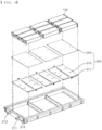
- the pair of the refrigerant transfer pipes 213 supplies and collects the refrigerant to and from the side frames 230. A detailed description related thereto will be given below.
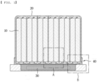
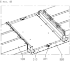
- a plurality of partition walls may be provided on the bottom surface of the pack case 200 such that the battery modules 100 are spaced apart from each other by a predetermined distance.
- the cooling unit 300 which is configured to remove heat generated from the battery modules 100, is located between the battery modules 100 and an inside upper surface of the pack case 200, and includes a heat sink 310 and a first heat dissipation plate 320 between the heat sink 310 and the pack case 200. A detailed description related thereto will be given below.
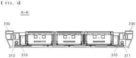
- FIG. 4 is a sectional view taken along line A-A' of FIG. 2
- FIG. 5 is a perspective view showing a side frame according to a preferred embodiment of the present invention
- FIG. 6 is a perspective view illustrating coupling of the side frame according to the preferred embodiment of the present invention.
- the pair of side frames 230 is spaced apart from each other by a predetermined distance in order to connect the front frame 210 and the rear frame 220 to each other, and each side frame 230 is provided with a refrigerant circulation channel 231 connected to a corresponding one of the refrigerant transfer pipes 213, an air circulation channel 232, an incision portion 233, and a fastening hole 234.
- the refrigerant circulation channel 231 connected to one side of the refrigerant transfer pipe 213 is configured to have a shape extending through the side frame 230 in a longitudinal direction thereof. Consequently, a cool refrigerant to be supplied to the heat sink 310 flows in the refrigerant circulation channel 231 connected to the refrigerant transfer pipe 213 communicating with the refrigerant introduction port 211, and a refrigerant heated to a predetermined temperature as a result of heat absorption moves in the refrigerant circulation channel 231 connected to the refrigerant transfer pipe 213 communicating with the refrigerant discharge port 212.
- the refrigerant circulation channel is separately manufactured and is then connected to the side surface or the bottom surface of the pack case, and therefore the refrigerant circulation channel may be easily damaged due to external impact. Furthermore, there is a problem in that a refrigerant that leaks from the refrigerant circulation channel as a result of damage to the refrigerant circulation channel may cause a new event.
- the refrigerant circulation channel 231 according to the present invention is provided in the side frame 230, and therefore there are advantages in that a danger of damage to the refrigerant circulation channel due to external impact may be minimized and the overall volume of the battery pack may be reduced.
- the air circulation channel 232 is located in the state in which a separation wall is disposed between the air circulation channel and the refrigerant circulation channel 231 such that no refrigerant leaks into the air circulation channel. At this time, the air circulation channel extends long parallel to the refrigerant circulation channel 231 such that the refrigerant moving in the refrigerant circulation channel 231 is cooled as naturally as possible.
- the air circulation channel 232 is provided with at least one incision portion 233, through which external air may pass, whereby more efficient cooling is possible. That is, since the air circulation channel 232 is further provided in the side frame 230 along the refrigerant circulation channel 231, it is possible to rapidly cool the battery pack and to reduce the overall weight of the battery pack.
- each of the pair of side frames 230 is provided in the bottom surface thereof with at least one fastening hole 234 configured to communicate with the refrigerant circulation channel 231, more specifically fastening holes 234 equal in number to refrigerant inlets 311 or refrigerant outlets 312 of the heat sink 310 located under the battery modules 100.
- the fastening holes 234 formed in the bottom surface of the side frame 230 are respectively fixed to the refrigerant inlets 311 of the heat sink 310 by fastening. Consequently, a refrigerant introduced into the refrigerant introduction port 211 sequentially moves along the refrigerant transfer pipe 213 and the refrigerant circulation channel 231 and is then supplied to the refrigerant inlets 311 of the heat sink 310.
- the other side frame 230 connected to the refrigerant discharge port 212 and the refrigerant transfer pipe 213 has the same coupling structure as described above, and a heated refrigerant is circulated in the order of the refrigerant outlets 312 of the heat sink 310, the refrigerant transfer pipe 213, and the refrigerant discharge port 212.
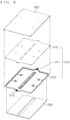
- FIG. 7 is an exploded perspective view of a cooling unit according to a preferred embodiment of the present invention.
- the cooling unit 300 includes a heat sink 310, a first heat dissipation plate 320, and a second heat dissipation plate 330.
- the heat sink 310 is constituted by a pair of a lower plate 310' and an upper plate 310" in order to provide a space in which a refrigerant is circulated.
- the lower plate 310' is provided with a pair of a refrigerant inlet 311 and a refrigerant outlet 312 facing each other, to which the fastening holes 234 formed in the bottom surfaces of the side frames 230 are coupled, as previously described.
- the first heat dissipation plate 320 is located between the heat sink 310 and the battery modules 100
- the second heat dissipation plate 330 is located under the heat sink 310, whereby heat generated from the battery modules 100 is transmitted to the heat sink 310.
- first heat dissipation plate 320 and the second heat dissipation plate 330 are located at the upper surface and the lower surface of the heat sink 310, respectively, so as to wrap the heat sink 310 once more, there is an advantage in that, even in the case in which refrigerant leakage occurs, it is possible to prevent the refrigerant from permeating into the battery pack.
- each of the heat sink 310, the first heat dissipation plate 320, and the second heat dissipation plate 330 prefferably be made of a material that exhibits high thermal conductivity, such as aluminum.
- FIG. 8 is a partial perspective view illustrating a battery pack according to a second preferred embodiment of the present invention.
- the battery pack according to the second preferred embodiment of the present invention may further include a refrigerant circulation pipe 313.
- a refrigerant is circulated along the refrigerant circulation channel 231 of the side frame 230, whereas the refrigerant circulation pipe 313 is further provided in the second embodiment.
- the refrigerant transfer pipe 213 and the refrigerant circulation pipe 313 are connected to each other such that a refrigerant introduced into or discharged from the refrigerant transfer pipe 213 passes though the refrigerant circulation pipe 313, and the refrigerant circulation pipe 313 is disposed in the refrigerant circulation channel 231 of the side frame 230.
- the refrigerant circulation pipe 313 is located in the refrigerant circulation channel 231, as described above, it is possible to securely prevent leakage of the refrigerant, thus inhibiting occurrence of an event, even in the case in which the side case 230 is damaged due to external impact.
Landscapes
- Chemical & Material Sciences (AREA)
- Chemical Kinetics & Catalysis (AREA)
- Electrochemistry (AREA)
- General Chemical & Material Sciences (AREA)
- Engineering & Computer Science (AREA)
- Manufacturing & Machinery (AREA)
- Secondary Cells (AREA)
- Battery Mounting, Suspending (AREA)
Claims (7)
- Batteriepack, welcher einen Kühlmittel-Zirkulationskanal (231) aufweist, welcher in einem Packgehäuse (200) bereitgestellt ist, der Batteriepack umfassend:wenigstens ein Batteriemodul (100);ein Packgehäuse (200), welches dazu eingerichtet ist, das Batteriemodul (100) darin aufzunehmen; undeine Kühleinheit (300), welche zwischen einer inneren oberen Fläche des Packgehäuses (200) und dem Batteriemodul (100) angeordnet ist, wobei die Kühleinheit (300) dazu eingerichtet ist, Wärme abzugeben, welche von dem Batteriemodul (100) erzeugt wird, wobeidas Packgehäuse (200) mit einem Kühlmittel-Zirkulationskanal (231) darin bereitgestellt ist, welcher dazu eingerichtet ist, ein Kühlmittel zu und von der Kühleinheit (300) zu liefern und zu sammeln,wobei das Packgehäuse (200) einen vorderen Rahmen (210), einen hinteren Rahmen (220) und ein Paar von Seitenrahmen (230) umfasst, welche den vorderen Rahmen (210) und den hinteren Rahmen (220) miteinander verbinden, und der Kühlmittel-Zirkulationskanal (231) in jedem aus dem Paar von Seitenrahmen (230) bereitgestellt ist,dadurch gekennzeichnet, dass ein Luft-Zirkulationskanal (232) benachbart zu dem Kühlmittel-Zirkulationskanal (231) des Seitenrahmens (230) angeordnet ist, um so parallel zu dem Kühlmittel-Zirkulationskanal (231) zu sein, undwobei der Luft-Zirkulationskanal (232) wenigstens einen Einschnittsabschnitt (233) aufweist, welcher dazu eingerichtet ist, es externer Luft zu erlauben,dahindurchzutreten.
- Batteriepack nach Anspruch 1, wobei der vordere Rahmen (210) ein Paar aus einem Kühlmittel-Einlassanschluss (211) und einem Kühlmittel-Auslassanschluss (212) aufweist, welche voneinander um eine vorbestimmte Distanz beabstandet sind, und eine Kühlmittel-Transferleitung (213) in Kommunikation mit dem Kühlmittel-Zirkulationskanal (231) mit jedem aus dem Kühlmittel-Einlassanschluss (211) und dem Kühlmittel-Auslassanschluss (212) verbunden ist.
- Batteriepack nach Anspruch 1, wobei die Kühleinheit (300) umfasst:eine Wärmesenke (310);eine erste Wärme-Verteilplatte (320), welche zwischen der Wärmesenke (310) und dem Packgehäuse (200) angeordnet ist; undeine zweite Wärme-Verteilplatte (330), welche zwischen der Wärmesenke (310) und einer unteren Fläche des Packgehäuses (200) angeordnet ist.
- Batteriepack nach Anspruch 3, wobei die Wärmesenke (310) umfasst:ein Paar aus einer unteren Platte (310') und einer oberen Platte (310"), welches dazu eingerichtet ist, einen Raum bereitzustellen, in welchem ein Kühlmittel zirkuliert wird; undeinen Kühlmittel-Einlass (311) und einen Kühlmittel-Auslass (312), welche lösbar mit dem Kühlmittel-Zirkulationskanal (231) gekoppelt sind.
- Batteriepack nach Anspruch 4, wobei eine untere Fläche des Seitenrahmens (230) Befestigungslöcher (234) aufweist, welche mit dem Kühlmittel-Einlass (311) und dem Kühlmittel-Auslass (312) verbunden sind.
- Batteriepack nach Anspruch 1, wobei der Kühlmittel-Zirkulationskanal (321) des Packgehäuses (200) eine Kühlmittel-Zirkulationsleitung (313) aufweist, welche darin aufgenommen und dazu eingerichtet ist, das Kühlmittel zu und von der Kühleinheit (300) zu liefern und zu sammeln.
- Vorrichtung, umfassend den Batteriepack nach einem der Ansprüche 1 bis 6.
Applications Claiming Priority (2)
| Application Number | Priority Date | Filing Date | Title |
|---|---|---|---|
| KR1020200066467A KR102805880B1 (ko) | 2020-06-02 | 2020-06-02 | 팩 케이스에 냉매 순환로가 구비한 전지 팩 |
| PCT/KR2021/005535 WO2021246657A1 (ko) | 2020-06-02 | 2021-05-03 | 팩 케이스에 냉매 순환로가 구비한 전지 팩 |
Publications (3)
| Publication Number | Publication Date |
|---|---|
| EP4080646A1 EP4080646A1 (de) | 2022-10-26 |
| EP4080646A4 EP4080646A4 (de) | 2024-06-19 |
| EP4080646B1 true EP4080646B1 (de) | 2025-07-02 |
Family
ID=78831501
Family Applications (1)
| Application Number | Title | Priority Date | Filing Date |
|---|---|---|---|
| EP21818804.3A Active EP4080646B1 (de) | 2020-06-02 | 2021-05-03 | Batteriepack, das einen kühlmittelkreislauf im pack-gehäuse aufweist |
Country Status (8)
| Country | Link |
|---|---|
| US (1) | US20230378567A1 (de) |
| EP (1) | EP4080646B1 (de) |
| JP (1) | JP7362051B2 (de) |
| KR (1) | KR102805880B1 (de) |
| CN (1) | CN115136389A (de) |
| ES (1) | ES3036950T3 (de) |
| HU (1) | HUE072289T2 (de) |
| WO (1) | WO2021246657A1 (de) |
Family Cites Families (23)
| Publication number | Priority date | Publication date | Assignee | Title |
|---|---|---|---|---|
| JP5777734B2 (ja) * | 2011-02-22 | 2015-09-09 | エルジー ケム. エルティーディ. | 冷却効率の改善された冷却部材及びそれを用いたバッテリーモジュール |
| DE102011084660B4 (de) * | 2011-10-18 | 2018-02-15 | Bayerische Motoren Werke Aktiengesellschaft | Vorrichtung zur Spannungsversorgung |
| KR101560563B1 (ko) * | 2012-09-19 | 2015-10-16 | 주식회사 엘지화학 | 냉각 효율성이 향상된 이차전지 |
| KR20140140795A (ko) * | 2013-05-30 | 2014-12-10 | 삼성에스디아이 주식회사 | 배터리 모듈 |
| KR101589996B1 (ko) * | 2013-06-07 | 2016-01-29 | 주식회사 엘지화학 | 액상 냉매 유출에 대한 안전성이 향상된 전지팩 |
| KR101743700B1 (ko) * | 2014-10-07 | 2017-06-05 | 주식회사 엘지화학 | 배터리 모듈 |
| KR101806415B1 (ko) * | 2014-12-19 | 2017-12-07 | 주식회사 엘지화학 | 냉각효율이 향상된 이차전지 셀 및 이를 포함하는 모듈형 전지 |
| KR102314041B1 (ko) * | 2015-03-12 | 2021-10-18 | 삼성에스디아이 주식회사 | 베터리 팩 |
| GB2541203B (en) * | 2015-08-11 | 2019-02-06 | Jaguar Land Rover Ltd | Apparatus for supporting a battery with integrated cooling channels |
| CN107785511B (zh) * | 2016-08-30 | 2019-11-22 | 比亚迪股份有限公司 | 电池模组、动力电池包及汽车 |
| KR101818922B1 (ko) * | 2016-12-01 | 2018-01-18 | 연암공과대학교산학협력단 | 강제 냉각이 가능한 전기자동차용 배터리 팩 |
| KR101947887B1 (ko) * | 2017-01-03 | 2019-02-13 | 삼성에스디아이 주식회사 | 배터리 팩 하우징 |
| KR102258816B1 (ko) * | 2017-06-27 | 2021-05-31 | 주식회사 엘지에너지솔루션 | 배터리 모듈 |
| KR102050025B1 (ko) | 2017-09-04 | 2020-01-08 | 주식회사 엘지화학 | 냉각수 직접 접촉 냉각 방식의 배터리 팩 |
| KR20190032843A (ko) * | 2017-09-20 | 2019-03-28 | 에스케이이노베이션 주식회사 | 이차 전지용 배터리 모듈 및 이를 포함하는 배터리 팩 |
| KR102301195B1 (ko) * | 2017-12-01 | 2021-09-09 | 주식회사 엘지에너지솔루션 | 배터리 팩 |
| WO2019146238A1 (ja) * | 2018-01-25 | 2019-08-01 | 三洋電機株式会社 | 電源装置及び電源装置を備える車両並びに蓄電装置 |
| EP3584877A1 (de) * | 2018-05-16 | 2019-12-25 | Samsung SDI Co., Ltd. | Batteriepack mit einem rahmenprofil mit integralen kühlkreislaufelementen |
| WO2019221376A1 (ko) * | 2018-05-16 | 2019-11-21 | 삼성에스디아이 주식회사 | 일체형 냉매 회로 부재를 갖는 프레임 프로파일을 포함한 전지 팩 |
| KR102151039B1 (ko) | 2018-11-30 | 2020-09-03 | 한국생산기술연구원 | 태양열 에너지를 이용한 바이오매스 제조장치 |
| CN109713177B (zh) * | 2018-11-30 | 2021-12-17 | 东风汽车有限公司 | 电动汽车动力电池下壳 |
| CN210040354U (zh) * | 2019-08-14 | 2020-02-07 | 嘉兴泽通新能源科技有限公司 | 一种电池箱 |
| CN210516779U (zh) * | 2019-09-19 | 2020-05-12 | 厦门金龙汽车新能源科技有限公司 | 一种水冷动力电池箱结构 |
-
2020
- 2020-06-02 KR KR1020200066467A patent/KR102805880B1/ko active Active
-
2021
- 2021-05-03 US US17/909,841 patent/US20230378567A1/en active Pending
- 2021-05-03 CN CN202180015921.3A patent/CN115136389A/zh active Pending
- 2021-05-03 HU HUE21818804A patent/HUE072289T2/hu unknown
- 2021-05-03 ES ES21818804T patent/ES3036950T3/es active Active
- 2021-05-03 EP EP21818804.3A patent/EP4080646B1/de active Active
- 2021-05-03 WO PCT/KR2021/005535 patent/WO2021246657A1/ko not_active Ceased
- 2021-05-03 JP JP2022548025A patent/JP7362051B2/ja active Active
Also Published As
| Publication number | Publication date |
|---|---|
| CN115136389A (zh) | 2022-09-30 |
| ES3036950T3 (en) | 2025-09-26 |
| HUE072289T2 (hu) | 2025-11-28 |
| WO2021246657A1 (ko) | 2021-12-09 |
| KR102805880B1 (ko) | 2025-05-12 |
| US20230378567A1 (en) | 2023-11-23 |
| EP4080646A4 (de) | 2024-06-19 |
| JP7362051B2 (ja) | 2023-10-17 |
| KR20210149431A (ko) | 2021-12-09 |
| EP4080646A1 (de) | 2022-10-26 |
| JP2023512819A (ja) | 2023-03-29 |
Similar Documents
| Publication | Publication Date | Title |
|---|---|---|
| US20240030517A1 (en) | Battery Module Having Improved Cooling Structure | |
| EP4087020A1 (de) | Batteriepack mit in mehreren schichten gestapelten batteriemodulen | |
| JP5000107B2 (ja) | フィルム外装電気デバイス集合体 | |
| EP4071892B1 (de) | Akkusatz mit einer aussenliegenden kühleinheit | |
| KR102802530B1 (ko) | 전지 팩 및 이를 포함하는 디바이스 | |
| KR102792214B1 (ko) | 전지 팩 및 이를 포함하는 디바이스 | |
| JP7636089B2 (ja) | 電池モジュールおよびそれを含む電池パック | |
| KR20210133886A (ko) | 전지팩 및 이를 포함하는 디바이스 | |
| CN114388871B (zh) | 电池组和包括所述电池组的装置 | |
| EP4239766A1 (de) | Batteriepack | |
| EP4099482B1 (de) | Batteriemodul mit verbesserter kühleffizienz und batteriepack damit | |
| EP4080646B1 (de) | Batteriepack, das einen kühlmittelkreislauf im pack-gehäuse aufweist | |
| US20230361383A1 (en) | Battery module having bent trap portion and battery pack including the same | |
| US20250038351A1 (en) | Battery pack | |
| KR20250147389A (ko) | 향상된 냉각성능을 가지는 배터리 팩 | |
| KR20250124527A (ko) | 전지 모듈 및 이를 포함하는 전지팩 | |
| KR20250177601A (ko) | 배터리 팩 | |
| KR20250147380A (ko) | 향상된 냉각성능을 가지는 배터리 팩 | |
| KR20240114910A (ko) | 배터리 팩 |
Legal Events
| Date | Code | Title | Description |
|---|---|---|---|
| STAA | Information on the status of an ep patent application or granted ep patent |
Free format text: STATUS: THE INTERNATIONAL PUBLICATION HAS BEEN MADE |
|
| PUAI | Public reference made under article 153(3) epc to a published international application that has entered the european phase |
Free format text: ORIGINAL CODE: 0009012 |
|
| STAA | Information on the status of an ep patent application or granted ep patent |
Free format text: STATUS: REQUEST FOR EXAMINATION WAS MADE |
|
| 17P | Request for examination filed |
Effective date: 20220721 |
|
| AK | Designated contracting states |
Kind code of ref document: A1 Designated state(s): AL AT BE BG CH CY CZ DE DK EE ES FI FR GB GR HR HU IE IS IT LI LT LU LV MC MK MT NL NO PL PT RO RS SE SI SK SM TR |
|
| DAV | Request for validation of the european patent (deleted) | ||
| DAX | Request for extension of the european patent (deleted) | ||
| A4 | Supplementary search report drawn up and despatched |
Effective date: 20240522 |
|
| RIC1 | Information provided on ipc code assigned before grant |
Ipc: H01M 50/20 20210101ALI20240515BHEP Ipc: H01M 10/613 20140101ALI20240515BHEP Ipc: H01M 10/6551 20140101ALI20240515BHEP Ipc: H01M 10/6566 20140101ALI20240515BHEP Ipc: H01M 10/6568 20140101ALI20240515BHEP Ipc: H01M 10/6556 20140101AFI20240515BHEP |
|
| REG | Reference to a national code |
Ref country code: DE Ref legal event code: R079 Free format text: PREVIOUS MAIN CLASS: H01M0010655600 Ipc: H01M0010655400 Ref country code: DE Ref legal event code: R079 Ref document number: 602021033507 Country of ref document: DE Free format text: PREVIOUS MAIN CLASS: H01M0010655600 Ipc: H01M0010655400 |
|
| GRAP | Despatch of communication of intention to grant a patent |
Free format text: ORIGINAL CODE: EPIDOSNIGR1 |
|
| STAA | Information on the status of an ep patent application or granted ep patent |
Free format text: STATUS: GRANT OF PATENT IS INTENDED |
|
| INTG | Intention to grant announced |
Effective date: 20250225 |
|
| RIC1 | Information provided on ipc code assigned before grant |
Ipc: H01M 50/204 20210101ALI20250214BHEP Ipc: H01M 10/6568 20140101ALI20250214BHEP Ipc: H01M 10/6566 20140101ALI20250214BHEP Ipc: H01M 10/6551 20140101ALI20250214BHEP Ipc: H01M 10/613 20140101ALI20250214BHEP Ipc: H01M 50/20 20210101ALI20250214BHEP Ipc: H01M 10/6556 20140101ALI20250214BHEP Ipc: H01M 10/6554 20140101AFI20250214BHEP |
|
| GRAS | Grant fee paid |
Free format text: ORIGINAL CODE: EPIDOSNIGR3 |
|
| P01 | Opt-out of the competence of the unified patent court (upc) registered |
Free format text: CASE NUMBER: APP_13961/2025 Effective date: 20250321 |
|
| GRAA | (expected) grant |
Free format text: ORIGINAL CODE: 0009210 |
|
| STAA | Information on the status of an ep patent application or granted ep patent |
Free format text: STATUS: THE PATENT HAS BEEN GRANTED |
|
| AK | Designated contracting states |
Kind code of ref document: B1 Designated state(s): AL AT BE BG CH CY CZ DE DK EE ES FI FR GB GR HR HU IE IS IT LI LT LU LV MC MK MT NL NO PL PT RO RS SE SI SK SM TR |
|
| REG | Reference to a national code |
Ref country code: GB Ref legal event code: FG4D |
|
| REG | Reference to a national code |
Ref country code: CH Ref legal event code: EP |
|
| REG | Reference to a national code |
Ref country code: DE Ref legal event code: R096 Ref document number: 602021033507 Country of ref document: DE |
|
| REG | Reference to a national code |
Ref country code: IE Ref legal event code: FG4D |
|
| REG | Reference to a national code |
Ref country code: ES Ref legal event code: FG2A Ref document number: 3036950 Country of ref document: ES Kind code of ref document: T3 Effective date: 20250926 |
|
| REG | Reference to a national code |
Ref country code: NL Ref legal event code: MP Effective date: 20250702 |
|
| REG | Reference to a national code |
Ref country code: HU Ref legal event code: AG4A Ref document number: E072289 Country of ref document: HU |
|
| PG25 | Lapsed in a contracting state [announced via postgrant information from national office to epo] |
Ref country code: PT Free format text: LAPSE BECAUSE OF FAILURE TO SUBMIT A TRANSLATION OF THE DESCRIPTION OR TO PAY THE FEE WITHIN THE PRESCRIBED TIME-LIMIT Effective date: 20251103 |
|
| PG25 | Lapsed in a contracting state [announced via postgrant information from national office to epo] |
Ref country code: NL Free format text: LAPSE BECAUSE OF FAILURE TO SUBMIT A TRANSLATION OF THE DESCRIPTION OR TO PAY THE FEE WITHIN THE PRESCRIBED TIME-LIMIT Effective date: 20250702 |
|
| REG | Reference to a national code |
Ref country code: AT Ref legal event code: MK05 Ref document number: 1810327 Country of ref document: AT Kind code of ref document: T Effective date: 20250702 |
|
| PG25 | Lapsed in a contracting state [announced via postgrant information from national office to epo] |
Ref country code: IS Free format text: LAPSE BECAUSE OF FAILURE TO SUBMIT A TRANSLATION OF THE DESCRIPTION OR TO PAY THE FEE WITHIN THE PRESCRIBED TIME-LIMIT Effective date: 20251102 |
|
| PG25 | Lapsed in a contracting state [announced via postgrant information from national office to epo] |
Ref country code: NO Free format text: LAPSE BECAUSE OF FAILURE TO SUBMIT A TRANSLATION OF THE DESCRIPTION OR TO PAY THE FEE WITHIN THE PRESCRIBED TIME-LIMIT Effective date: 20251002 |
|
| REG | Reference to a national code |
Ref country code: LT Ref legal event code: MG9D |
|
| PG25 | Lapsed in a contracting state [announced via postgrant information from national office to epo] |
Ref country code: AT Free format text: LAPSE BECAUSE OF FAILURE TO SUBMIT A TRANSLATION OF THE DESCRIPTION OR TO PAY THE FEE WITHIN THE PRESCRIBED TIME-LIMIT Effective date: 20250702 |
|
| PG25 | Lapsed in a contracting state [announced via postgrant information from national office to epo] |
Ref country code: FI Free format text: LAPSE BECAUSE OF FAILURE TO SUBMIT A TRANSLATION OF THE DESCRIPTION OR TO PAY THE FEE WITHIN THE PRESCRIBED TIME-LIMIT Effective date: 20250702 |
|
| PG25 | Lapsed in a contracting state [announced via postgrant information from national office to epo] |
Ref country code: HR Free format text: LAPSE BECAUSE OF FAILURE TO SUBMIT A TRANSLATION OF THE DESCRIPTION OR TO PAY THE FEE WITHIN THE PRESCRIBED TIME-LIMIT Effective date: 20250702 |
|
| PG25 | Lapsed in a contracting state [announced via postgrant information from national office to epo] |
Ref country code: GR Free format text: LAPSE BECAUSE OF FAILURE TO SUBMIT A TRANSLATION OF THE DESCRIPTION OR TO PAY THE FEE WITHIN THE PRESCRIBED TIME-LIMIT Effective date: 20251003 |
|
| PG25 | Lapsed in a contracting state [announced via postgrant information from national office to epo] |
Ref country code: CZ Free format text: LAPSE BECAUSE OF FAILURE TO SUBMIT A TRANSLATION OF THE DESCRIPTION OR TO PAY THE FEE WITHIN THE PRESCRIBED TIME-LIMIT Effective date: 20250702 Ref country code: SE Free format text: LAPSE BECAUSE OF FAILURE TO SUBMIT A TRANSLATION OF THE DESCRIPTION OR TO PAY THE FEE WITHIN THE PRESCRIBED TIME-LIMIT Effective date: 20250702 |
|
| PG25 | Lapsed in a contracting state [announced via postgrant information from national office to epo] |
Ref country code: LV Free format text: LAPSE BECAUSE OF FAILURE TO SUBMIT A TRANSLATION OF THE DESCRIPTION OR TO PAY THE FEE WITHIN THE PRESCRIBED TIME-LIMIT Effective date: 20250702 |
|
| PG25 | Lapsed in a contracting state [announced via postgrant information from national office to epo] |
Ref country code: PL Free format text: LAPSE BECAUSE OF FAILURE TO SUBMIT A TRANSLATION OF THE DESCRIPTION OR TO PAY THE FEE WITHIN THE PRESCRIBED TIME-LIMIT Effective date: 20250702 Ref country code: BG Free format text: LAPSE BECAUSE OF FAILURE TO SUBMIT A TRANSLATION OF THE DESCRIPTION OR TO PAY THE FEE WITHIN THE PRESCRIBED TIME-LIMIT Effective date: 20250702 |
|
| PG25 | Lapsed in a contracting state [announced via postgrant information from national office to epo] |
Ref country code: RS Free format text: LAPSE BECAUSE OF FAILURE TO SUBMIT A TRANSLATION OF THE DESCRIPTION OR TO PAY THE FEE WITHIN THE PRESCRIBED TIME-LIMIT Effective date: 20251002 |