EP4099482B1 - Batteriemodul mit verbesserter kühleffizienz und batteriepack damit - Google Patents
Batteriemodul mit verbesserter kühleffizienz und batteriepack damit Download PDFInfo
- Publication number
- EP4099482B1 EP4099482B1 EP21869559.1A EP21869559A EP4099482B1 EP 4099482 B1 EP4099482 B1 EP 4099482B1 EP 21869559 A EP21869559 A EP 21869559A EP 4099482 B1 EP4099482 B1 EP 4099482B1
- Authority
- EP
- European Patent Office
- Prior art keywords
- battery
- battery module
- support plate
- module according
- heat sink
- Prior art date
- Legal status (The legal status is an assumption and is not a legal conclusion. Google has not performed a legal analysis and makes no representation as to the accuracy of the status listed.)
- Active
Links
Images


Classifications
-
- H—ELECTRICITY
- H01—ELECTRIC ELEMENTS
- H01M—PROCESSES OR MEANS, e.g. BATTERIES, FOR THE DIRECT CONVERSION OF CHEMICAL ENERGY INTO ELECTRICAL ENERGY
- H01M10/00—Secondary cells; Manufacture thereof
- H01M10/60—Heating or cooling; Temperature control
- H01M10/65—Means for temperature control structurally associated with the cells
- H01M10/655—Solid structures for heat exchange or heat conduction
- H01M10/6554—Rods or plates
-
- H—ELECTRICITY
- H01—ELECTRIC ELEMENTS
- H01M—PROCESSES OR MEANS, e.g. BATTERIES, FOR THE DIRECT CONVERSION OF CHEMICAL ENERGY INTO ELECTRICAL ENERGY
- H01M10/00—Secondary cells; Manufacture thereof
- H01M10/60—Heating or cooling; Temperature control
- H01M10/65—Means for temperature control structurally associated with the cells
- H01M10/655—Solid structures for heat exchange or heat conduction
- H01M10/6551—Surfaces specially adapted for heat dissipation or radiation, e.g. fins or coatings
-
- H—ELECTRICITY
- H01—ELECTRIC ELEMENTS
- H01M—PROCESSES OR MEANS, e.g. BATTERIES, FOR THE DIRECT CONVERSION OF CHEMICAL ENERGY INTO ELECTRICAL ENERGY
- H01M10/00—Secondary cells; Manufacture thereof
- H01M10/60—Heating or cooling; Temperature control
- H01M10/61—Types of temperature control
- H01M10/613—Cooling or keeping cold
-
- H—ELECTRICITY
- H01—ELECTRIC ELEMENTS
- H01M—PROCESSES OR MEANS, e.g. BATTERIES, FOR THE DIRECT CONVERSION OF CHEMICAL ENERGY INTO ELECTRICAL ENERGY
- H01M10/00—Secondary cells; Manufacture thereof
- H01M10/60—Heating or cooling; Temperature control
- H01M10/62—Heating or cooling; Temperature control specially adapted for specific applications
- H01M10/625—Vehicles
-
- H—ELECTRICITY
- H01—ELECTRIC ELEMENTS
- H01M—PROCESSES OR MEANS, e.g. BATTERIES, FOR THE DIRECT CONVERSION OF CHEMICAL ENERGY INTO ELECTRICAL ENERGY
- H01M10/00—Secondary cells; Manufacture thereof
- H01M10/60—Heating or cooling; Temperature control
- H01M10/65—Means for temperature control structurally associated with the cells
- H01M10/653—Means for temperature control structurally associated with the cells characterised by electrically insulating or thermally conductive materials
-
- H—ELECTRICITY
- H01—ELECTRIC ELEMENTS
- H01M—PROCESSES OR MEANS, e.g. BATTERIES, FOR THE DIRECT CONVERSION OF CHEMICAL ENERGY INTO ELECTRICAL ENERGY
- H01M10/00—Secondary cells; Manufacture thereof
- H01M10/60—Heating or cooling; Temperature control
- H01M10/65—Means for temperature control structurally associated with the cells
- H01M10/655—Solid structures for heat exchange or heat conduction
- H01M10/6553—Terminals or leads
-
- H—ELECTRICITY
- H01—ELECTRIC ELEMENTS
- H01M—PROCESSES OR MEANS, e.g. BATTERIES, FOR THE DIRECT CONVERSION OF CHEMICAL ENERGY INTO ELECTRICAL ENERGY
- H01M50/00—Constructional details or processes of manufacture of the non-active parts of electrochemical cells other than fuel cells, e.g. hybrid cells
- H01M50/20—Mountings; Secondary casings or frames; Racks, modules or packs; Suspension devices; Shock absorbers; Transport or carrying devices; Holders
- H01M50/271—Lids or covers for the racks or secondary casings
-
- H—ELECTRICITY
- H01—ELECTRIC ELEMENTS
- H01M—PROCESSES OR MEANS, e.g. BATTERIES, FOR THE DIRECT CONVERSION OF CHEMICAL ENERGY INTO ELECTRICAL ENERGY
- H01M50/00—Constructional details or processes of manufacture of the non-active parts of electrochemical cells other than fuel cells, e.g. hybrid cells
- H01M50/50—Current conducting connections for cells or batteries
- H01M50/502—Interconnectors for connecting terminals of adjacent batteries; Interconnectors for connecting cells outside a battery casing
- H01M50/507—Interconnectors for connecting terminals of adjacent batteries; Interconnectors for connecting cells outside a battery casing comprising an arrangement of two or more busbars within a container structure, e.g. busbar modules
-
- H—ELECTRICITY
- H01—ELECTRIC ELEMENTS
- H01M—PROCESSES OR MEANS, e.g. BATTERIES, FOR THE DIRECT CONVERSION OF CHEMICAL ENERGY INTO ELECTRICAL ENERGY
- H01M10/00—Secondary cells; Manufacture thereof
- H01M10/60—Heating or cooling; Temperature control
- H01M10/64—Heating or cooling; Temperature control characterised by the shape of the cells
- H01M10/647—Prismatic or flat cells, e.g. pouch cells
-
- H—ELECTRICITY
- H01—ELECTRIC ELEMENTS
- H01M—PROCESSES OR MEANS, e.g. BATTERIES, FOR THE DIRECT CONVERSION OF CHEMICAL ENERGY INTO ELECTRICAL ENERGY
- H01M10/00—Secondary cells; Manufacture thereof
- H01M10/60—Heating or cooling; Temperature control
- H01M10/65—Means for temperature control structurally associated with the cells
- H01M10/655—Solid structures for heat exchange or heat conduction
- H01M10/6554—Rods or plates
- H01M10/6555—Rods or plates arranged between the cells
-
- H—ELECTRICITY
- H01—ELECTRIC ELEMENTS
- H01M—PROCESSES OR MEANS, e.g. BATTERIES, FOR THE DIRECT CONVERSION OF CHEMICAL ENERGY INTO ELECTRICAL ENERGY
- H01M10/00—Secondary cells; Manufacture thereof
- H01M10/60—Heating or cooling; Temperature control
- H01M10/65—Means for temperature control structurally associated with the cells
- H01M10/655—Solid structures for heat exchange or heat conduction
- H01M10/6556—Solid parts with flow channel passages or pipes for heat exchange
- H01M10/6557—Solid parts with flow channel passages or pipes for heat exchange arranged between the cells
-
- H—ELECTRICITY
- H01—ELECTRIC ELEMENTS
- H01M—PROCESSES OR MEANS, e.g. BATTERIES, FOR THE DIRECT CONVERSION OF CHEMICAL ENERGY INTO ELECTRICAL ENERGY
- H01M2220/00—Batteries for particular applications
- H01M2220/20—Batteries in motive systems, e.g. vehicle, ship, plane
-
- H—ELECTRICITY
- H01—ELECTRIC ELEMENTS
- H01M—PROCESSES OR MEANS, e.g. BATTERIES, FOR THE DIRECT CONVERSION OF CHEMICAL ENERGY INTO ELECTRICAL ENERGY
- H01M50/00—Constructional details or processes of manufacture of the non-active parts of electrochemical cells other than fuel cells, e.g. hybrid cells
- H01M50/20—Mountings; Secondary casings or frames; Racks, modules or packs; Suspension devices; Shock absorbers; Transport or carrying devices; Holders
- H01M50/204—Racks, modules or packs for multiple batteries or multiple cells
- H01M50/207—Racks, modules or packs for multiple batteries or multiple cells characterised by their shape
- H01M50/211—Racks, modules or packs for multiple batteries or multiple cells characterised by their shape adapted for pouch cells
-
- H—ELECTRICITY
- H01—ELECTRIC ELEMENTS
- H01M—PROCESSES OR MEANS, e.g. BATTERIES, FOR THE DIRECT CONVERSION OF CHEMICAL ENERGY INTO ELECTRICAL ENERGY
- H01M50/00—Constructional details or processes of manufacture of the non-active parts of electrochemical cells other than fuel cells, e.g. hybrid cells
- H01M50/20—Mountings; Secondary casings or frames; Racks, modules or packs; Suspension devices; Shock absorbers; Transport or carrying devices; Holders
- H01M50/262—Mountings; Secondary casings or frames; Racks, modules or packs; Suspension devices; Shock absorbers; Transport or carrying devices; Holders with fastening means, e.g. locks
- H01M50/264—Mountings; Secondary casings or frames; Racks, modules or packs; Suspension devices; Shock absorbers; Transport or carrying devices; Holders with fastening means, e.g. locks for cells or batteries, e.g. straps, tie rods or peripheral frames
-
- H—ELECTRICITY
- H01—ELECTRIC ELEMENTS
- H01M—PROCESSES OR MEANS, e.g. BATTERIES, FOR THE DIRECT CONVERSION OF CHEMICAL ENERGY INTO ELECTRICAL ENERGY
- H01M50/00—Constructional details or processes of manufacture of the non-active parts of electrochemical cells other than fuel cells, e.g. hybrid cells
- H01M50/50—Current conducting connections for cells or batteries
- H01M50/502—Interconnectors for connecting terminals of adjacent batteries; Interconnectors for connecting cells outside a battery casing
- H01M50/503—Interconnectors for connecting terminals of adjacent batteries; Interconnectors for connecting cells outside a battery casing characterised by the shape of the interconnectors
-
- Y—GENERAL TAGGING OF NEW TECHNOLOGICAL DEVELOPMENTS; GENERAL TAGGING OF CROSS-SECTIONAL TECHNOLOGIES SPANNING OVER SEVERAL SECTIONS OF THE IPC; TECHNICAL SUBJECTS COVERED BY FORMER USPC CROSS-REFERENCE ART COLLECTIONS [XRACs] AND DIGESTS
- Y02—TECHNOLOGIES OR APPLICATIONS FOR MITIGATION OR ADAPTATION AGAINST CLIMATE CHANGE
- Y02E—REDUCTION OF GREENHOUSE GAS [GHG] EMISSIONS, RELATED TO ENERGY GENERATION, TRANSMISSION OR DISTRIBUTION
- Y02E60/00—Enabling technologies; Technologies with a potential or indirect contribution to GHG emissions mitigation
- Y02E60/10—Energy storage using batteries
Definitions
- the present invention relates to a battery module and a battery pack including the same, and more particularly to a battery module configured such that the area of heat exchange between a battery cell, which generates heat, and a heat sink is increased and heat exchange between a busbar and the heat sink is also performed, whereby cooling performance of the battery module is improved, and a battery pack including the same.
- the secondary batteries which are being capable of being charged and discharged, are intimately used in daily life.
- the secondary batteries are used in mobile devices, electric vehicles, and hybrid electric vehicles.
- a plurality of battery cells is connected to each other in series or in parallel in order to increase capacity and output of the battery module or the battery pack.
- a problem such as overload
- a problem may occur, since the plurality of battery cells is connected to each other.
- a heat sink configured to remove heat generated in a battery in order to maintain battery temperature.
- FIG. 1 is a sectional view showing a cooling structure of a conventional battery module.
- the conventional battery module includes a plurality of battery cells 20 disposed perpendicular to a heat sink 10 and a pair of cooling plates 40 connected perpendicularly to the heat sink 10, the cooling plates being in direct contact with a busbar assembly 30.
- the conventional battery module is configured to have a structure in which heat generated from the battery cells 20 and the busbar assembly 30 is removed by the heat sink 10 and the cooling plates 40.
- a heat dissipation effect is low, and the size of the battery module is large.
- the heat sink 10 and the battery cells 20 are in contact with each other in a state of being disposed perpendicular to each other, the area of contact therebetween is small, whereby it is difficult to rapidly remove heat generated from the battery cells 20 and a heat dissipation effect is low. Furthermore, separate cooling plates 40 and heat transfer members 50 are needed in order to cool the busbar assembly 30, whereby the overall volume of the battery module is increased, and therefore energy density of the battery module is reduced.
- Patent Document 1 Korean Patent Application Publication No. 2020-0030968
- Document JP 2014 157721 A relates to a battery module configured by combining laminate type cells and a battery assembly including a stacked body in which a plurality of battery modules are stacked.
- Document JP 2018 006043 A relates to a battery system that can be accommodated in a narrow space.
- Document EP 3 018 731 B1 relates to a battery pack having an easily cooled structure.
- the present invention has been made in view of the above problems, and it is an object of the present invention to provide a battery module with improved cooling performance capable of inhibiting occurrence of a secondary problem due to heat generation by efficiently removing heat generated from a battery cell and a battery pack including the same.
- a battery module includes a heat sink (100) having a predetermined area, the heat sink being horizontally located; a support plate (200) including an upper support plate (210) and a lower support plate (220) located respectively at the upper surface and the lower surface of the heat sink (100); a battery cell (500) including a first battery cell (510) disposed in tight contact with the upper support plate (210) and a second battery cell (520) disposed in tight contact with the lower support plate (220); and a cover plate (600) including an upper cover plate (610) located above the first battery cell (510) and a lower cover plate (620) located under the second battery cell (520).
- the heat sink (100) is provided on the upper surface thereof with a protuberance (110) protruding by a predetermined height, and the upper support plate (210) is provided with a first opening (211) configured to receive the protuberance (110).
- the first battery cell (510) is located at the upper surface of the protuberance (110).
- the heat sink (100) may be provided on the lower surface thereof with a protuberance (110) protruding by a predetermined height, and the lower support plate (220) may be provided with a second opening (221) configured to receive the protuberance (110).
- the second battery cell (520) may be located at the lower surface of the protuberance (110).
- a thermally conductive resin layer may be interposed between the first battery cell (510) and the protuberance (110) and between the second battery cell (520) and the protuberance (110).
- first support frames (410) may be located between the upper support plate (210) and the upper cover plate (610) so as to extend along opposite edges of each thereof while having a predetermined height and width.
- a first support frame (410) may be located between the upper support plate (210) and the upper cover plate (610) so as to extend along the middle of each thereof while having a predetermined height and width.
- second support frames (420) may be located between the lower support plate (220) and the lower cover plate (620) so as to extend along opposite edges of each thereof while having a predetermined height and width.
- a second support frame (420) may be located between the lower support plate (220) and the lower cover plate (620) so as to extend along the middle of each thereof while having a predetermined height and width.
- a first busbar assembly (310) may be located between the upper support plate (210) and the upper cover plate (610).
- the first busbar assembly (310) may include a first busbar frame (311) having a first receiving recess (311(a)) formed therein and a busbar (312) seated in the first receiving recess (311(a)), the busbar (312) being configured to have a concave-convex structure that is bent at a predetermined angle a plurality of times.
- a second busbar assembly (320) may be located between the lower support plate (220) and the lower cover plate (620).
- the present invention provides a battery pack including a battery module having at least one of the above-mentioned features.
- the present invention provides a device including the battery pack.
- a battery module with improved cooling performance according to the present invention and a battery pack including the same have an advantage in that relatively wide side surfaces of battery cells and a heat sink are in tight contact with each other in a state of being located in a horizontal direction, whereby cooling performance of the battery cells is improved due to an increase in heat transfer area.
- the battery module with improved cooling performance according to the present invention and the battery pack including the same have a merit in that the heat sink, which is configured to cool the battery cells, and a busbar are in contact with each other, whereby no separate heat sink is necessary.
- the battery module with improved cooling performance according to the present invention and the battery pack including the same have an advantage in that the battery cells, the heat sink, a support plate, etc. are fastened to each other via a plurality of support frames and fastening members, whereby it is possible to maintain uniform adhesion force between the battery cells and the heat sink while maximizing space utilization.
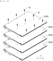
- FIG. 2 is a perspective view of a battery pack according to a preferred embodiment of the present invention
- FIG. 3 is an exploded perspective view of the battery pack shown in FIG. 2
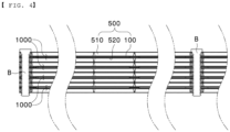
- FIG. 4 is a sectional view taken along line A-A' of FIG. 2 .
- the battery pack according to the present invention is configured such that a plurality of battery modules 1000 is horizontally stacked.
- the battery modules 1000 are fixed using a plurality of fastening members B.
- each of the fastening members B may be, for example, a bolt provided with a screw thread, and a nut, which is fastened to the portion of the fastening member that protrudes from the lower surface of a lower cover plate 620 after being inserted through the battery pack, may be further provided.
- the battery modules 1000 may be received in a separate case (not shown) in the state in which the battery modules are fixed using the fastening members B. Depending on circumstances, after being received in the case (not shown), the battery modules 1000 may be fixed together with the case (not shown) using the fastening members B.
- FIG. 5 is an exploded perspective view of a battery module according to a preferred embodiment of the present invention.
- the battery module 1000 includes a heat sink 100, a support plate 200, a busbar assembly 300, a support frame 400, battery cells 500, and a cover plate 600.
- the heat sink 100 is a flat plate that is provided with a flow channel defined therein and has a predetermined area.
- a plurality of protuberances 110 is formed on the upper surface and the lower surface of the heat sink 100 so as to protrude therefrom in a state of being spaced apart from each other by a predetermined distance.
- the protuberances 110 will be described below in detail.
- the support plate 200 includes an upper support plate 210 and a lower support plate 220 located at opposite surfaces of the heat sink 100, more specifically the upper surface of the heat sink 100 and the lower surface of the heat sink 100, respectively.
- the busbar assembly 300 configured to electrically connect the battery cells 500 to each other includes a first busbar assembly 310 and a second busbar assembly 320.
- the first busbar assembly 310 is located at the upper surface of the upper support plate 210, and the second busbar assembly 320 is disposed at the lower surface of the lower support plate 220.
- a total of six first busbar assemblies 310 one of which is located in the vicinity of each of opposite edges of the upper support plate 210 and four of which are located between the two first busbar assemblies located in the vicinity of the opposite edges of the upper support plate in a state of being spaced apart from each other by a predetermined distance in a longitudinal direction (an X-axis direction), are shown in the figure, which, however, is merely an example.
- the number or position of first busbar assemblies may be changed as long as the first busbar assemblies can be brought into tight contact with the upper support plate 210.
- the second busbar assemblies 320 are symmetrical with the first busbar assemblies 310, and therefore an additional description thereof will be omitted.
- the support frame 400 includes first support frames 410 and second support frames 420.
- the first support frames 410 are located between the upper support plate 210 and an upper cover plate 610
- the second support frames 420 are located between the lower support plate 220 and the lower cover plate 620.
- the first support frames and the second support frames will be described below in more detail.
- the battery cells 500 include a plurality of first battery cells 510 and a plurality of second battery cells 520 located parallel to the heat sink 100. Specifically, the first battery cells 510 are located between the upper support plate 210 and the upper cover plate 610, and the second battery cells 520 are located between the lower support plate 220 and the lower cover plate 620.
- the first battery cells 510 and the second battery cells 520 may be battery cells having the same construction.
- each battery cell may include a cell case, in which an electrode assembly (not shown) is received, and a pair of electrode leads.
- the electrode assembly may be a jelly-roll type assembly, which is configured to have a structure in which a long sheet type positive electrode and a long sheet type negative electrode are wound in the state in which a separator is interposed therebetween, a stacked type assembly which is configured to have a structure in which a rectangular positive electrode and a rectangular negative electrode are stacked in the state in which a separator is interposed therebetween, a stacked and folded type assembly, which is configured to have a structure in which unit cells are wound using a long separation film, or a laminated and stacked type assembly, which is configured to have a structure in which battery cells are stacked in the state in which a separator is interposed therebetween and are then attached to each other.
- the present invention is not limited thereto. It is preferable for the electrode assembly according to the present invention to be a stacked and folded type assembly or a laminated and stacked type assembly, which has lowest physical stress when a curved module is formed.
- the electrode assembly is received in the cell case.
- the cell case is generally configured to have a laminate sheet structure including an inner layer, a metal layer, and an outer layer.
- the inner layer is disposed in direct contact with the electrode assembly, and therefore the inner layer must exhibit high insulation properties and high resistance to an electrolytic solution.
- the inner layer must exhibit high sealability in order to hermetically seal the cell case from the outside, i.e. a thermally-bonded sealed portion between inner layers must exhibit excellent thermal bonding strength.
- the inner layer may be made of a material selected from among a polyolefin-based resin, such as polypropylene, polyethylene, polyethylene acrylate, or polybutylene, a polyurethane resin, and a polyimide resin, which exhibit excellent chemical resistance and high sealability.
- polypropylene which exhibits excellent mechanical-physical properties, such as tensile strength, rigidity, surface hardness, and impact strength resistance, and excellent chemical resistance, is the most preferably used.
- the metal layer which is disposed so as to abut the inner layer, corresponds to a barrier layer configured to prevent moisture or various kinds of gas from permeating into the battery from the outside.
- An aluminum thin film which is light and easily shapeable, may be used as a preferred material for the metal layer.
- the outer layer is provided on the other surface of the metal layer.
- the outer layer may be made of a heat-resistant polymer that exhibits excellent tensile strength, resistance to moisture permeation, and resistance to air transmission such that the outer layer exhibits high heat resistance and chemical resistance while protecting the electrode assembly.
- the outer layer may be made of nylon or polyethylene terephthalate.
- the present invention is not limited thereto.
- the pair of electrode leads is constituted by a positive electrode lead and a negative electrode lead, which may be exposed from the cell case in a state of being electrically connected respectively to positive electrode tabs and negative electrode tabs of the electrode assembly or may be directly connected to the electrode assembly in the state in which tabs are omitted.
- the cover plate 600 serves to protect the battery cells 500 from the outside, and includes an upper cover plate 610 and a lower cover plate 620.
- the upper cover plate 610 is located above the first battery cells 510 to protect the upper surfaces of the first battery cells 510
- the lower cover plate 620 is located above the second battery cells 520 to protect the lower surfaces of the second battery cells 520.
- Each of the upper cover plate 610 and the lower cover plate 620 is provided with a plurality of through-holes formed so as to be spaced apart from each other by a predetermined distance such that the fastening members B are inserted therethrough.
- FIG. 6 is a perspective view illustrating a coupling structure between the heat sink and the support plate in the battery module according to the preferred embodiment of the present invention.
- the upper support plate 210 is located at the upper surface of the heat sink 100 according to the present invention, and the lower support plate 220 is located at the lower surface of the heat sink 100.
- the protuberances 110 are formed on the opposite surfaces of the heat sink 100, i.e. the upper surface and the lower surface of the heat sink, so as to protrude therefrom by a predetermined height while having a predetermined shape. It is more preferable for the upper support plate 210 to have first openings 211 configured to receive the protuberances 110 formed on the upper surface of the heat sink 100 and for the lower support plate 220 to have second openings 221 configured to receive the protuberances 110 formed on the lower surface of the heat sink 100.
- the protuberances 110 formed on the upper surface of the heat sink 100 are inserted into the first openings 211, and the protuberances 110 formed on the lower surface of the heat sink 100 are inserted into the second openings 221, whereby rolling of the heat sink from side to side may be prevented.
- each of the upper support plate 210 and the lower support plate 220 may be made of a thermally conductive resin.
- a coolant inlet port 120 configured to supply a coolant is provided at one side of the heat sink 100, and a coolant outlet port 130 configured to discharge the coolant that has performed heat exchange is provided in the vicinity of the coolant inlet port. It is obvious that the coolant inlet port 120 and the coolant outlet port 130 are not necessarily located so as to be adjacent to each other as long as it is possible to supply and discharge the coolant.
- the heat sink 100 and the support plate 200 are provided with through-holes, through which the fastening members B are inserted.
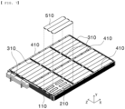
- FIG. 7 is a perspective view illustrating a battery cell mounting structure in the battery module according to the preferred embodiment of the present invention
- FIG. 8 is a perspective view illustrating a support frame disposition structure in the battery module according to the preferred embodiment of the present invention.
- the plurality of first battery cells 510 according to the present invention is horizontally seated on the protuberances 110 of the heat sink 100, exposed to the outside in a state of being inserted through the first openings 211 of the upper support plate 210, and the upper support plate 210.
- a conventional battery module is configured to have a structure in which battery cells are located perpendicular to a heat sink, whereby contact area between the battery cells and the heat sink is small, and therefore cooling performance of the battery module is limited.
- the battery module 1000 is configured to have a structure in which the first battery cells 510 are located parallel to the heat sink 100 and in which the horizontal side surfaces of the first battery cells 510 contact the protuberances 110 of the heat sink 100, whereby rapid heat transfer is achieved, and therefore heat transfer efficiency is improved.
- a known thermally conductive resin layer may be interposed between each of the protuberances 110 and a corresponding one of the first battery cells 510 in order to fix the protuberance and the first battery cell to each other.
- the structure in which the second battery cells 520 and the lower support plate 220 are mounted is identical to the structure in which the first battery cells 510 and the upper support plate 210 are coupled to each other except for only difference in direction, and therefore a detailed description thereof will be omitted.
- the support frame 400 includes the first support frames 410 and the second support frames 420.
- the first support frames 410 are located between the upper support plate 210 and the upper cover plate 610, more specifically at opposite edges and the middle of the upper support plate 210 in the longitudinal direction of the battery module (the X-axis direction).
- Each of the first support frames is a bar that has a predetermined width, height, and length and that has an approximately quadrangular section.
- Each of the first support frames 410 is provided with a plurality of first through-holes 411 formed so as to be spaced apart from each other by a predetermined distance such that the fastening members B can be inserted therethrough.
- the second support frames 420 are identical in construction to the first support frames 410 except that the second support frames are located between the lower support plate 220 and the lower cover plate 620. That is, each of the second support frames 420 is provided with a plurality of second through-holes 421 formed so as to be spaced apart from each other by a predetermined distance such that the fastening members B can be inserted therethrough.
- the support plate 200 and the cover plate 600 may be maintained spaced apart from each other by a predetermined distance by the first support frames 410 and the second support frames 420, whereby it is possible to prevent the battery cells 500 from being pressed more than necessary and to inhibit local expansion at the time of swelling.
- FIG. 9 is a perspective view illustrating a coupling structure between the battery cells and busbars in the battery module according to the preferred embodiment of the present invention.
- the busbar assembly 300 includes a first busbar assembly 310 and a second busbar assembly 320, which are identical in construction to each other except for only difference in disposition.
- a description will be given based on the first busbar assembly 310.
- the first busbar assembly 310 includes a first busbar frame 311 and busbars 312.
- the first busbar frame 311 is configured to electrically connect adjacent ones of the busbars 312 to each other while supporting the busbars 312.
- the first busbar frame 311 is provided with first receiving recesses 311(a) configured to receive the busbars 312 in a seated state and second receiving recesses 311(b) depressed deeper than the first receiving recesses 311(a).
- the busbar 312 having the above construction When the busbar 312 having the above construction is seated in the receiving recesses of the first busbar frame 311, the first horizontal portion 312(a) is inserted into the first receiving recess 311(a), and the second horizontal portion 312(b) is inserted into the second receiving recess 311(b), whereby the busbar 312 is securely fastened to the first busbar frame 311.
- the conventional battery module has no function of cooling the busbar assembly 300 or further needs to have such a cooling function.
- the busbar assembly 300 is located in surface contact on the upper support plate 210 and the lower support plate 220 located respectively at the upper surface and the lower surface of the heat sink 100, whereby it is possible to cool the busbar assembly 300 using only the heat sink 100, which is configured to cool the battery cells, and therefore it is possible to minimize an increase in volume of the battery module.
- the present invention may provide a battery pack including a battery module 1000 having at least one of the above-mentioned features, and the battery pack may be mounted in a device, such as an electric vehicle, a hybrid electric vehicle, or a plug-in hybrid electric vehicle.
Landscapes
- Chemical & Material Sciences (AREA)
- Chemical Kinetics & Catalysis (AREA)
- Electrochemistry (AREA)
- General Chemical & Material Sciences (AREA)
- Engineering & Computer Science (AREA)
- Manufacturing & Machinery (AREA)
- Battery Mounting, Suspending (AREA)
- Secondary Cells (AREA)
- Connection Of Batteries Or Terminals (AREA)
Claims (13)
- Batteriemodul, umfassend:einen Kühlkörper (100), welcher eine vorbestimmte Fläche aufweist, wobei der Kühlkörper horizontal angeordnet ist;eine Halterungsplatte (200), welche eine obere Halterungsplatte (210) und eine untere Halterungsplatte (220) umfasst, welche an einer oberen Fläche bzw. einer unteren Fläche des Kühlkörpers (100) angeordnet sind;eine Batteriezelle (500), welche eine erste Batteriezelle (510), die in engem Kontakt mit der oberen Halterungsplatte (210) angeordnet ist, und eine zweite Batteriezelle (520) umfasst, die in engem Kontakt mit der unteren Halterungsplatte (220) angeordnet ist; undeine Abdeckplatte (600), welche eine obere Abdeckplatte (610), die oberhalb der ersten Batteriezelle (510) angeordnet ist, und eine untere Abdeckplatte (620) umfasst, die unterhalb der zweiten Batteriezelle (520) angeordnet ist,dadurch gekennzeichnet, dassder Kühlkörper (100) an der oberen Fläche davon mit einer Erhebung (110) bereitgestellt ist, welche mit einer vorbestimmten Höhe vorsteht, undwobei die obere Halterungsplatte (210) mit einer ersten Öffnung (211) bereitgestellt ist, welche dazu eingerichtet ist, die Erhebung (110) aufzunehmen; undwobei die erste Batteriezelle (510) an einer oberen Fläche der Erhebung (110) angeordnet ist.
- Batteriemodul nach Anspruch 1, wobei der Kühlkörper (100) an der unteren Fläche davon mit einer Erhebung (110) bereitgestellt ist, welche mit einer vorbestimmten Höhe vorsteht, und
wobei die untere Halterungsplatte (220) mit einer zweiten Öffnung (221) bereitgestellt ist, welche dazu eingerichtet ist, die Erhebung (110) aufzunehmen. - Batteriemodul nach Anspruch 2, wobei die zweite Batteriezelle (520) an einer unteren Fläche der Erhebung (110) angeordnet ist.
- Batteriemodul nach Anspruch 2, wobei eine thermisch leitfähige Harzschicht zwischen der ersten Batteriezelle (510) und der Erhebung (110) und zwischen der zweiten Batteriezelle (520) und der Erhebung (110) eingefügt ist.
- Batteriemodul nach Anspruch 1, wobei erste Halterungsrahmen (410) derart zwischen der oberen Halterungsplatte (210) und der oberen Abdeckplatte (610) angeordnet sind, dass sie sich entlang entgegengesetzter Ränder jeder davon erstrecken, während sie eine vorbestimmte Höhe und eine vorbestimmte Breite aufweisen.
- Batteriemodul nach Anspruch 5, wobei ein erster Halterungsrahmen (410) derart zwischen der oberen Halterungsplatte (210) und der oberen Abdeckplatte (610) angeordnet ist, dass er sich entlang einer Mitte jeder davon erstreckt, während er eine vorbestimmte Höhe und eine vorbestimmte Breite aufweist.
- Batteriemodul nach Anspruch 1, wobei zweite Halterungsrahmen (420) derart zwischen der unteren Halterungsplatte (220) und der unteren Abdeckplatte (620) angeordnet sind, dass sie sich entlang entgegengesetzter Ränder jeder davon erstrecken, während sie eine vorbestimmte Höhe und eine vorbestimmte Breite aufweisen.
- Batteriemodul nach Anspruch 7, wobei ein zweiter Halterungsrahmen (420) derart zwischen der unteren Halterungsplatte (220) und der unteren Abdeckplatte (620) angeordnet ist, dass er sich entlang einer Mitte jeder davon erstreckt, während er eine vorbestimmte Höhe und eine vorbestimmte Breite aufweist.
- Batteriemodul nach Anspruch 1, wobei eine erste Sammelschienenanordnung (310) zwischen der oberen Halterungsplatte (210) und der oberen Abdeckplatte (610) angeordnet ist.
- Batteriemodul nach Anspruch 9, wobei die erste Sammelschienenanordnung (310) umfasst:einen ersten Sammelschienenrahmen (311), welcher eine erste Aufnahmeaussparung (311(a)) aufweist, welche darin gebildet ist; undeine Sammelschiene (312), welche in der ersten Aufnahmeaussparung (311(a)) aufgenommen ist, wobei die Sammelschiene (312) dazu eingerichtet ist, eine konkavkonvexe Struktur aufzuweisen, welche mehrere Male in einem vorbestimmten Winkel gebogen ist.
- Batteriemodul nach Anspruch 1, wobei eine zweite Sammelschienenanordnung (320) zwischen der unteren Halterungsplatte (220) und der unteren Abdeckplatte (620) angeordnet ist.
- Batteriepack, umfassend das Batteriemodul nach einem der Ansprüche 1 bis 11, wobei das Batteriemodul in einer Mehrzahl gestapelt ist, um in einer vertikalen Richtung nebeneinander angeordnet zu sein.
- Vorrichtung, umfassend den Batteriepack nach Anspruch 12.
Applications Claiming Priority (2)
| Application Number | Priority Date | Filing Date | Title |
|---|---|---|---|
| KR1020200121150A KR102902481B1 (ko) | 2020-09-21 | 2020-09-21 | 냉각성능이 향상된 전지 모듈 및 이를 포함하는 전지 팩 |
| PCT/KR2021/011016 WO2022059936A1 (ko) | 2020-09-21 | 2021-08-19 | 냉각성능이 향상된 전지 모듈 및 이를 포함하는 전지 팩 |
Publications (3)
| Publication Number | Publication Date |
|---|---|
| EP4099482A1 EP4099482A1 (de) | 2022-12-07 |
| EP4099482A4 EP4099482A4 (de) | 2024-08-21 |
| EP4099482B1 true EP4099482B1 (de) | 2025-06-11 |
Family
ID=80776250
Family Applications (1)
| Application Number | Title | Priority Date | Filing Date |
|---|---|---|---|
| EP21869559.1A Active EP4099482B1 (de) | 2020-09-21 | 2021-08-19 | Batteriemodul mit verbesserter kühleffizienz und batteriepack damit |
Country Status (8)
| Country | Link |
|---|---|
| US (1) | US20230352764A1 (de) |
| EP (1) | EP4099482B1 (de) |
| JP (1) | JP7625319B2 (de) |
| KR (1) | KR102902481B1 (de) |
| CN (1) | CN115398715A (de) |
| ES (1) | ES3035642T3 (de) |
| HU (1) | HUE072252T2 (de) |
| WO (1) | WO2022059936A1 (de) |
Families Citing this family (2)
| Publication number | Priority date | Publication date | Assignee | Title |
|---|---|---|---|---|
| KR102872648B1 (ko) * | 2022-06-03 | 2025-10-16 | 주식회사 엘지에너지솔루션 | 배터리 팩 |
| CN115939653A (zh) * | 2022-10-28 | 2023-04-07 | 孚能科技(赣州)股份有限公司 | 电池包和电池系统 |
Family Cites Families (14)
| Publication number | Priority date | Publication date | Assignee | Title |
|---|---|---|---|---|
| DE602006009687D1 (de) * | 2005-11-08 | 2009-11-19 | Byd Co Ltd | Wärmeableiteinrichtung für ein batteriepack und batteriepack damit |
| US8632923B2 (en) * | 2010-07-02 | 2014-01-21 | Samsung Sdi Co., Ltd. | Battery pack |
| US8852781B2 (en) | 2012-05-19 | 2014-10-07 | Lg Chem, Ltd. | Battery cell assembly and method for manufacturing a cooling fin for the battery cell assembly |
| JP6091921B2 (ja) * | 2013-02-15 | 2017-03-08 | 本田技研工業株式会社 | 電池モジュール及び組電池 |
| US9786967B2 (en) * | 2014-05-27 | 2017-10-10 | Lg Chem, Ltd. | Battery pack and method of controlling an electric fan in the battery pack |
| JP6331863B2 (ja) * | 2014-08-11 | 2018-05-30 | 株式会社オートネットワーク技術研究所 | 蓄電モジュール |
| KR101748360B1 (ko) * | 2014-12-01 | 2017-06-16 | 주식회사 엘지화학 | 배터리 모듈 |
| KR102314041B1 (ko) * | 2015-03-12 | 2021-10-18 | 삼성에스디아이 주식회사 | 베터리 팩 |
| JP6697332B2 (ja) * | 2016-06-28 | 2020-05-20 | 三洋電機株式会社 | バッテリシステム及びバッテリシステムを備える電動車両 |
| KR20180091600A (ko) * | 2017-02-07 | 2018-08-16 | 에스케이이노베이션 주식회사 | 직접냉각 배터리 팩 |
| KR102301195B1 (ko) * | 2017-12-01 | 2021-09-09 | 주식회사 엘지에너지솔루션 | 배터리 팩 |
| KR102204302B1 (ko) | 2018-09-13 | 2021-01-15 | 주식회사 엘지화학 | 배터리 모듈, 이러한 배터리 모듈을 포함하는 배터리 팩 및 이러한 배터리 팩을 포함하는 자동차 |
| KR102352686B1 (ko) * | 2018-09-28 | 2022-01-17 | 주식회사 엘지에너지솔루션 | 배터리 모듈, 이러한 배터리 모듈을 포함하는 배터리 팩 및 이러한 배터리 팩을 포함하는 자동차 |
| KR102700951B1 (ko) | 2019-04-15 | 2024-09-02 | 주식회사 엘지화학 | 액정 소자 |
-
2020
- 2020-09-21 KR KR1020200121150A patent/KR102902481B1/ko active Active
-
2021
- 2021-08-19 HU HUE21869559A patent/HUE072252T2/hu unknown
- 2021-08-19 US US17/909,519 patent/US20230352764A1/en active Pending
- 2021-08-19 JP JP2022562135A patent/JP7625319B2/ja active Active
- 2021-08-19 ES ES21869559T patent/ES3035642T3/es active Active
- 2021-08-19 EP EP21869559.1A patent/EP4099482B1/de active Active
- 2021-08-19 CN CN202180026042.0A patent/CN115398715A/zh active Pending
- 2021-08-19 WO PCT/KR2021/011016 patent/WO2022059936A1/ko not_active Ceased
Also Published As
| Publication number | Publication date |
|---|---|
| US20230352764A1 (en) | 2023-11-02 |
| HUE072252T2 (hu) | 2025-11-28 |
| EP4099482A4 (de) | 2024-08-21 |
| WO2022059936A1 (ko) | 2022-03-24 |
| JP2023521186A (ja) | 2023-05-23 |
| JP7625319B2 (ja) | 2025-02-03 |
| KR20220038848A (ko) | 2022-03-29 |
| KR102902481B1 (ko) | 2025-12-19 |
| EP4099482A1 (de) | 2022-12-07 |
| CN115398715A (zh) | 2022-11-25 |
| ES3035642T3 (en) | 2025-09-05 |
Similar Documents
| Publication | Publication Date | Title |
|---|---|---|
| EP3716392B1 (de) | Batteriemodul mit verbesserter kühlstruktur | |
| KR101205181B1 (ko) | 신규한 구조의 냉각부재와 이를 포함하는 전지모듈 | |
| KR101145719B1 (ko) | 우수한 방열 특성의 전지모듈 및 중대형 전지팩 | |
| US12394836B2 (en) | Battery pack having cooling unit provided outside case | |
| EP4191750B1 (de) | Batteriepack mit verbesserter kühlleistung sowie vorrichtung damit | |
| EP4087020A1 (de) | Batteriepack mit in mehreren schichten gestapelten batteriemodulen | |
| EP4099482B1 (de) | Batteriemodul mit verbesserter kühleffizienz und batteriepack damit | |
| EP4109645B1 (de) | Batteriepack mit batteriezelle mit erhöhter lebensdauer und vorrichtung damit | |
| EP4513648A2 (de) | Batteriepack mit erhöhter lebensdauer einer batteriezelle und vorrichtung damit | |
| KR102922440B1 (ko) | 전지셀의 수명이 향상된 전지 팩 및 이를 포함하는 디바이스 | |
| EP4080646B1 (de) | Batteriepack, das einen kühlmittelkreislauf im pack-gehäuse aufweist | |
| EP4167367A1 (de) | Batteriemodul mit gebogenem fallenteil und batteriepack damit | |
| KR20250099982A (ko) | 전지팩 및 이를 포함하는 디바이스 | |
| KR20250128005A (ko) | 전지 모듈 및 이를 포함하는 전지팩 | |
| CN120584429A (zh) | 电池模块和包括该电池模块的电池组 |
Legal Events
| Date | Code | Title | Description |
|---|---|---|---|
| STAA | Information on the status of an ep patent application or granted ep patent |
Free format text: STATUS: THE INTERNATIONAL PUBLICATION HAS BEEN MADE |
|
| PUAI | Public reference made under article 153(3) epc to a published international application that has entered the european phase |
Free format text: ORIGINAL CODE: 0009012 |
|
| STAA | Information on the status of an ep patent application or granted ep patent |
Free format text: STATUS: REQUEST FOR EXAMINATION WAS MADE |
|
| 17P | Request for examination filed |
Effective date: 20220829 |
|
| AK | Designated contracting states |
Kind code of ref document: A1 Designated state(s): AL AT BE BG CH CY CZ DE DK EE ES FI FR GB GR HR HU IE IS IT LI LT LU LV MC MK MT NL NO PL PT RO RS SE SI SK SM TR |
|
| DAV | Request for validation of the european patent (deleted) | ||
| DAX | Request for extension of the european patent (deleted) | ||
| A4 | Supplementary search report drawn up and despatched |
Effective date: 20240718 |
|
| RIC1 | Information provided on ipc code assigned before grant |
Ipc: H01M 50/503 20210101ALI20240712BHEP Ipc: H01M 50/211 20210101ALI20240712BHEP Ipc: H01M 10/6557 20140101ALI20240712BHEP Ipc: H01M 50/507 20210101ALI20240712BHEP Ipc: H01M 50/264 20210101ALI20240712BHEP Ipc: H01M 10/6555 20140101ALI20240712BHEP Ipc: H01M 10/653 20140101ALI20240712BHEP Ipc: H01M 10/647 20140101ALI20240712BHEP Ipc: H01M 10/625 20140101ALI20240712BHEP Ipc: H01M 50/20 20210101ALI20240712BHEP Ipc: H01M 50/502 20210101ALI20240712BHEP Ipc: H01M 10/613 20140101ALI20240712BHEP Ipc: H01M 10/6553 20140101ALI20240712BHEP Ipc: H01M 10/6551 20140101AFI20240712BHEP |
|
| RIC1 | Information provided on ipc code assigned before grant |
Ipc: H01M 50/503 20210101ALI20241219BHEP Ipc: H01M 50/211 20210101ALI20241219BHEP Ipc: H01M 10/6557 20140101ALI20241219BHEP Ipc: H01M 50/507 20210101ALI20241219BHEP Ipc: H01M 50/264 20210101ALI20241219BHEP Ipc: H01M 10/6555 20140101ALI20241219BHEP Ipc: H01M 10/653 20140101ALI20241219BHEP Ipc: H01M 10/647 20140101ALI20241219BHEP Ipc: H01M 10/625 20140101ALI20241219BHEP Ipc: H01M 50/20 20210101ALI20241219BHEP Ipc: H01M 50/502 20210101ALI20241219BHEP Ipc: H01M 10/613 20140101ALI20241219BHEP Ipc: H01M 10/6553 20140101ALI20241219BHEP Ipc: H01M 10/6551 20140101AFI20241219BHEP |
|
| GRAP | Despatch of communication of intention to grant a patent |
Free format text: ORIGINAL CODE: EPIDOSNIGR1 |
|
| STAA | Information on the status of an ep patent application or granted ep patent |
Free format text: STATUS: GRANT OF PATENT IS INTENDED |
|
| INTG | Intention to grant announced |
Effective date: 20250128 |
|
| P01 | Opt-out of the competence of the unified patent court (upc) registered |
Free format text: CASE NUMBER: APP_6060/2025 Effective date: 20250205 |
|
| GRAS | Grant fee paid |
Free format text: ORIGINAL CODE: EPIDOSNIGR3 |
|
| GRAA | (expected) grant |
Free format text: ORIGINAL CODE: 0009210 |
|
| STAA | Information on the status of an ep patent application or granted ep patent |
Free format text: STATUS: THE PATENT HAS BEEN GRANTED |
|
| AK | Designated contracting states |
Kind code of ref document: B1 Designated state(s): AL AT BE BG CH CY CZ DE DK EE ES FI FR GB GR HR HU IE IS IT LI LT LU LV MC MK MT NL NO PL PT RO RS SE SI SK SM TR |
|
| REG | Reference to a national code |
Ref country code: GB Ref legal event code: FG4D |
|
| REG | Reference to a national code |
Ref country code: CH Ref legal event code: EP |
|
| REG | Reference to a national code |
Ref country code: IE Ref legal event code: FG4D |
|
| REG | Reference to a national code |
Ref country code: DE Ref legal event code: R096 Ref document number: 602021032260 Country of ref document: DE |
|
| REG | Reference to a national code |
Ref country code: ES Ref legal event code: FG2A Ref document number: 3035642 Country of ref document: ES Kind code of ref document: T3 Effective date: 20250905 |
|
| PGFP | Annual fee paid to national office [announced via postgrant information from national office to epo] |
Ref country code: HU Payment date: 20250827 Year of fee payment: 5 |
|
| PG25 | Lapsed in a contracting state [announced via postgrant information from national office to epo] |
Ref country code: FI Free format text: LAPSE BECAUSE OF FAILURE TO SUBMIT A TRANSLATION OF THE DESCRIPTION OR TO PAY THE FEE WITHIN THE PRESCRIBED TIME-LIMIT Effective date: 20250611 |
|
| PGFP | Annual fee paid to national office [announced via postgrant information from national office to epo] |
Ref country code: ES Payment date: 20250911 Year of fee payment: 5 |
|
| PGFP | Annual fee paid to national office [announced via postgrant information from national office to epo] |
Ref country code: DE Payment date: 20250721 Year of fee payment: 5 |
|
| REG | Reference to a national code |
Ref country code: LT Ref legal event code: MG9D |
|
| PG25 | Lapsed in a contracting state [announced via postgrant information from national office to epo] |
Ref country code: GR Free format text: LAPSE BECAUSE OF FAILURE TO SUBMIT A TRANSLATION OF THE DESCRIPTION OR TO PAY THE FEE WITHIN THE PRESCRIBED TIME-LIMIT Effective date: 20250912 Ref country code: NO Free format text: LAPSE BECAUSE OF FAILURE TO SUBMIT A TRANSLATION OF THE DESCRIPTION OR TO PAY THE FEE WITHIN THE PRESCRIBED TIME-LIMIT Effective date: 20250911 |
|
| REG | Reference to a national code |
Ref country code: NL Ref legal event code: MP Effective date: 20250611 |
|
| PG25 | Lapsed in a contracting state [announced via postgrant information from national office to epo] |
Ref country code: BG Free format text: LAPSE BECAUSE OF FAILURE TO SUBMIT A TRANSLATION OF THE DESCRIPTION OR TO PAY THE FEE WITHIN THE PRESCRIBED TIME-LIMIT Effective date: 20250611 |
|
| PGFP | Annual fee paid to national office [announced via postgrant information from national office to epo] |
Ref country code: BE Payment date: 20250722 Year of fee payment: 5 Ref country code: GB Payment date: 20250722 Year of fee payment: 5 |
|
| PG25 | Lapsed in a contracting state [announced via postgrant information from national office to epo] |
Ref country code: HR Free format text: LAPSE BECAUSE OF FAILURE TO SUBMIT A TRANSLATION OF THE DESCRIPTION OR TO PAY THE FEE WITHIN THE PRESCRIBED TIME-LIMIT Effective date: 20250611 |
|
| PGFP | Annual fee paid to national office [announced via postgrant information from national office to epo] |
Ref country code: AT Payment date: 20251020 Year of fee payment: 5 Ref country code: FR Payment date: 20250725 Year of fee payment: 5 |
|
| PG25 | Lapsed in a contracting state [announced via postgrant information from national office to epo] |
Ref country code: RS Free format text: LAPSE BECAUSE OF FAILURE TO SUBMIT A TRANSLATION OF THE DESCRIPTION OR TO PAY THE FEE WITHIN THE PRESCRIBED TIME-LIMIT Effective date: 20250911 |
|
| PG25 | Lapsed in a contracting state [announced via postgrant information from national office to epo] |
Ref country code: LV Free format text: LAPSE BECAUSE OF FAILURE TO SUBMIT A TRANSLATION OF THE DESCRIPTION OR TO PAY THE FEE WITHIN THE PRESCRIBED TIME-LIMIT Effective date: 20250611 |
|
| PG25 | Lapsed in a contracting state [announced via postgrant information from national office to epo] |
Ref country code: NL Free format text: LAPSE BECAUSE OF FAILURE TO SUBMIT A TRANSLATION OF THE DESCRIPTION OR TO PAY THE FEE WITHIN THE PRESCRIBED TIME-LIMIT Effective date: 20250611 |
|
| REG | Reference to a national code |
Ref country code: HU Ref legal event code: AG4A Ref document number: E072252 Country of ref document: HU |
|
| PG25 | Lapsed in a contracting state [announced via postgrant information from national office to epo] |
Ref country code: PT Free format text: LAPSE BECAUSE OF FAILURE TO SUBMIT A TRANSLATION OF THE DESCRIPTION OR TO PAY THE FEE WITHIN THE PRESCRIBED TIME-LIMIT Effective date: 20251013 |
|
| REG | Reference to a national code |
Ref country code: AT Ref legal event code: MK05 Ref document number: 1802994 Country of ref document: AT Kind code of ref document: T Effective date: 20250611 |
|
| PG25 | Lapsed in a contracting state [announced via postgrant information from national office to epo] |
Ref country code: IS Free format text: LAPSE BECAUSE OF FAILURE TO SUBMIT A TRANSLATION OF THE DESCRIPTION OR TO PAY THE FEE WITHIN THE PRESCRIBED TIME-LIMIT Effective date: 20251011 |
|
| PG25 | Lapsed in a contracting state [announced via postgrant information from national office to epo] |
Ref country code: SM Free format text: LAPSE BECAUSE OF FAILURE TO SUBMIT A TRANSLATION OF THE DESCRIPTION OR TO PAY THE FEE WITHIN THE PRESCRIBED TIME-LIMIT Effective date: 20250611 Ref country code: AT Free format text: LAPSE BECAUSE OF FAILURE TO SUBMIT A TRANSLATION OF THE DESCRIPTION OR TO PAY THE FEE WITHIN THE PRESCRIBED TIME-LIMIT Effective date: 20250611 |
|
| PG25 | Lapsed in a contracting state [announced via postgrant information from national office to epo] |
Ref country code: CZ Free format text: LAPSE BECAUSE OF FAILURE TO SUBMIT A TRANSLATION OF THE DESCRIPTION OR TO PAY THE FEE WITHIN THE PRESCRIBED TIME-LIMIT Effective date: 20250611 |
|
| PG25 | Lapsed in a contracting state [announced via postgrant information from national office to epo] |
Ref country code: PL Free format text: LAPSE BECAUSE OF FAILURE TO SUBMIT A TRANSLATION OF THE DESCRIPTION OR TO PAY THE FEE WITHIN THE PRESCRIBED TIME-LIMIT Effective date: 20250611 |
|
| PG25 | Lapsed in a contracting state [announced via postgrant information from national office to epo] |
Ref country code: EE Free format text: LAPSE BECAUSE OF FAILURE TO SUBMIT A TRANSLATION OF THE DESCRIPTION OR TO PAY THE FEE WITHIN THE PRESCRIBED TIME-LIMIT Effective date: 20250611 |
|
| PG25 | Lapsed in a contracting state [announced via postgrant information from national office to epo] |
Ref country code: SK Free format text: LAPSE BECAUSE OF FAILURE TO SUBMIT A TRANSLATION OF THE DESCRIPTION OR TO PAY THE FEE WITHIN THE PRESCRIBED TIME-LIMIT Effective date: 20250611 |
|
| PG25 | Lapsed in a contracting state [announced via postgrant information from national office to epo] |
Ref country code: RO Free format text: LAPSE BECAUSE OF FAILURE TO SUBMIT A TRANSLATION OF THE DESCRIPTION OR TO PAY THE FEE WITHIN THE PRESCRIBED TIME-LIMIT Effective date: 20250611 |