EP4080562A2 - Kühler - Google Patents
Kühler Download PDFInfo
- Publication number
- EP4080562A2 EP4080562A2 EP22177689.1A EP22177689A EP4080562A2 EP 4080562 A2 EP4080562 A2 EP 4080562A2 EP 22177689 A EP22177689 A EP 22177689A EP 4080562 A2 EP4080562 A2 EP 4080562A2
- Authority
- EP
- European Patent Office
- Prior art keywords
- unit
- fins
- fin
- coolant
- cooler
- Prior art date
- Legal status (The legal status is an assumption and is not a legal conclusion. Google has not performed a legal analysis and makes no representation as to the accuracy of the status listed.)
- Granted
Links
Images


Classifications
-
- H—ELECTRICITY
- H05—ELECTRIC TECHNIQUES NOT OTHERWISE PROVIDED FOR
- H05K—PRINTED CIRCUITS; CASINGS OR CONSTRUCTIONAL DETAILS OF ELECTRIC APPARATUS; MANUFACTURE OF ASSEMBLAGES OF ELECTRICAL COMPONENTS
- H05K7/00—Constructional details common to different types of electric apparatus
- H05K7/20—Modifications to facilitate cooling, ventilating, or heating
- H05K7/20218—Modifications to facilitate cooling, ventilating, or heating using a liquid coolant without phase change in electronic enclosures
-
- H10W40/47—
-
- H—ELECTRICITY
- H05—ELECTRIC TECHNIQUES NOT OTHERWISE PROVIDED FOR
- H05K—PRINTED CIRCUITS; CASINGS OR CONSTRUCTIONAL DETAILS OF ELECTRIC APPARATUS; MANUFACTURE OF ASSEMBLAGES OF ELECTRICAL COMPONENTS
- H05K7/00—Constructional details common to different types of electric apparatus
- H05K7/20—Modifications to facilitate cooling, ventilating, or heating
- H05K7/2039—Modifications to facilitate cooling, ventilating, or heating characterised by the heat transfer by conduction from the heat generating element to a dissipating body
- H05K7/20409—Outer radiating structures on heat dissipating housings, e.g. fins integrated with the housing
- H05K7/20418—Outer radiating structures on heat dissipating housings, e.g. fins integrated with the housing the radiating structures being additional and fastened onto the housing
-
- H10W40/255—
Definitions
- the present invention relates to a cooler, which in particular is adapted for cooling electronic structural units or assemblies.
- the new high-performance processors deliver about 70 to 100 W over an area of about 10 cm 2 and thus achieve a far higher heat flux density.
- the processor manufacturers predict that a further increase in the waste heat is to be expected in the years ahead.
- liquid cooling more effectively dissipates the heat from the electronic assemblies, with the result that a higher power density is possible.
- Liquid coolers also allow more compact switch cabinets with numerous electronic components and operate very quietly.
- An exemplary generic cooling apparatus is disclosed in EP 2 291 859 A1 , in which an insert is provided inside a cooling channel, the insert having a plurality of pins forming channels towards a cooler wall and being supplied with coolant via openings in an inclined surface of the inlet which is hit by a coolant flow from the coolant channel.
- the invention provides an improved cooler, which, while being as compact as possible, permits a more effective cooling structure and a lighter, simpler design.
- the invention relates to a cooler comprising an inlet, an outlet, a first unit, and a second unit, the inlet configured for feeding the cooler with coolant, the outlet configured for discharging said coolant, the first unit comprising a first plane for receiving a first part to be cooled, a first unit first fin, and a first unit second fin, the first unit first fin extending from a first unit first root to a first unit first fin front, the first unit second fin extending from the first unit first root to a first unit second fin front, the first plane being in uninterrupted thermal contact with the first unit first root, the first unit first fin having a first unit first fin first surface, the first unit second fin having a first unit second fin first surface, the second unit comprising a second unit first fin, the second unit first fin having a second unit first fin first front, a second unit first fin first surface, and a second unit first fin second surface, the second unit first fin located at least in part between the first unit first fin and the first unit second fin such that the first unit first root is adjacent to
- At least one of the first unit second fin first surface and the second unit first fin second surface may have a second corrugated structure, the second corrugated structure forming first reverse channels between the first unit second fin first surface and the second unit first fin second surface, the first reverse channels being offset relative to the first inbound channels, each of two neighbouring first reverse channels, which are closest to the first inbound channel, being configured for receiving a part of the impinged and widened first coolant inbound flow and forming a first coolant reverse flow from the first unit first root towards the first unit second fin front.
- the second unit first fin first front may be a second unit first fin front, the first unit second fin having a first unit second fin second surface, the second unit comprising a second unit second fin, the second unit second fin having a second unit second fin front and a second unit second fin first surface, the second unit first fin extending from a second unit first root to the second unit first fin front, the second unit second fin extending from the second unit first root to the second unit second fin front, the first unit second fin located between the second unit first fin and the second unit second fin such that the second unit first root is adjacent to the first unit second fin front leaving a second gap, the first unit second fin second surface is abutting the second unit second fin first surface, the first reverse channels being second inbound channels, the first coolant reverse flow being a second coolant inbound flow, at least one second inbound channel being configured for forming the second coolant inbound flow from the second unit first fin front towards the second unit first root, causing the second coolant inbound flow to impinge and laterally widen on the second unit
- the second unit first fin may have a second unit first fin second front opposing the second unit first fin first front, wherein the cooler comprises a third unit, the third unit comprises a third unit first fin, and a third unit second fin, the third unit first fin extending from a third unit first root to a third unit first fin front, the third unit second fin extending from the third unit first root to a third unit second fin front, the third unit first fin having a third unit first fin first surface, the third unit second fin having a third unit second fin first surface.
- the second unit first fin is further located at least in part between the third unit first fin and the third unit second fin such that the third unit first root is adjacent to the second unit first fin second front leaving a third gap, the third unit first fin first surface is abutting the second unit first fin first surface, and the third unit second fin first surface is abutting the second unit first fin second surface.
- the second unit first fin may further be located at least in part neighbouring the third unit first fin such that the third unit first root is adjacent to the second unit first fin second front leaving a fourth gap, the third unit first fin first surface is abutting the second unit first fin second surface the third unit first root being arranged for receiving coolant from the inlet.
- the third unit may comprise a plane for receiving a second part to be cooled and the third plane being in uninterrupted thermal contact with the third unit first root.
- the cooler may be an electronic element cooler and the first part to be cooled being an electronic element.
- the second unit may be of a plastic material.
- the inlet may be arranged and configured to be upstream to the first gap, and the outlet being arranged and configured to be downstream to the first reverse channels.
- the first unit or the second unit is a finned component of a material containing aluminium.
- the first unit first root may be configured for causing a split-up of the first coolant inbound flow into two part-flows, the two part-flows entering said two neighbouring first reverse channels.
- the first unit first root is one side of a heat-conducting cooler wall, the first plane being an opposite side of the heat-conducting cooler wall.
- the first unit and the second unit may be configured for forming a housing.
- first unit and the third unit are configured for forming a housing, in particular and the second unit is configured for forming the housing in combination with the first and third unit.
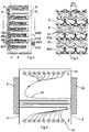
- FIG. 1 shows a first embodiment of a cooler 1 according to the invention.
- the cooler 1 has an inlet 2 and an outlet 3, a first unit 4 and a second unit 5.
- a first part to be cooled 6, in particular an electronic element, is applied on a first surface 7 of the first unit 4.
- the cooler is fed by the inlet 2 with coolant, which distributes in a lower part of the cooler, more or less evenly along a long side of the cooler, and is then guided forth and back through a plurality of channels formed by fins of the first and second unit until it arrives in an upper part of the cooler which accesses the outlet 3 where the coolant is discharged.
- the formations of the inlet 2 and/or outlet 3 can be part of the first and/or second unit or can be separate elements connectable with the first and second unit.
- the first and second unit can together form a housing.
- the first and second unit form a housing together with at least one of a separate inlet, a separate outlet, and a separate wall element.
- the fed coolant first comes into contact with a fin of the first unit.
- the first fin to come into contact with the coolant can also be from the second unit.
- the fins of the first and second unit intertwine, i.e. they are put together such that the fins of the first unit and the second unit alternate. In this way, the coolant is sent forth and back, at every turn impinging on the backside of the plate having the first surface 7.
- the area of impinging is named "root” in the following.
- the term "intertwine" is to be interpreted as implying the involved units both (a) having at least in some parts contact and (b) having at least in some parts no contact at all.
- figure 2 shows a section of the second unit of figure 1 . It is noted that such structure is by way of example only. The inventive principle can also be achieved with various other structures, as will be shown below.
- the fins 9 in figure 2 (“second unit fins") have a waved profile. They extend from a root section ("second unit roots”) to a front section ("second unit fronts").
- Figure 3 shows a cross-sectional view along the long side and perpendicular to an alignment of the corrugated structure of the fins.
- the first and second unit are stuck together, which is why the second unit fins 9 are visible here as well as first unit fins 8.
- a particular feature of the embodiment of figure 3 is that a longitudinal orientation of the fins a slight inclination in order to further improve an even longitudinal distribution of the coolant to achieve a uniform pressure drop.
- this inclination is optional and not necessary in all embodiments of the invention.
- Each of the corrugated structures has for example a waved pattern, a zigzag pattern, a meander pattern, or a trapezoidal pattern
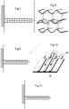
- Figure 4 shows a side view such that the long side is essentially perpendicular to the paper level and one can see the single fins 8 of the first unit and the single fins 9 of the second unit being intertwined.
- the coolant by which the cooler is fed arrives below the first fin of the first unit 8 on the bottom where it distributes along the long side.
- the coolant finds its way around the front section F11 of said first fin to travel between said first fin of the first unit and the first fin of the second unit. This mechanism will be explained more generally for figure 6 below. Said travel between two fins takes place in channels which are formed with a corrugated structure on at least one of the participating fins.
- Figure 5 shows an example for this formation of channels, which is in accordance with the structure of the fins in figures 1 to 4 where the fins of both of the first and second unit have a waved form.
- Figure 5 shows the cross-section view of figure 3 in greater detail from the first unit 4 towards the second unit 5. This cross-section view corresponds to the cut plane A indicated in figure 4 .
- the fins are arranged and abutting one another in such a way that said waves are offset relative to each other to form the channels. That is to say, the reverse channels are shifted by the offset O1 relative to the inbound channels.
- a coolant flow is indicated by the full arrows and the dashed arrows.
- the full arrow flow could be seen from the perspective of the cutting plane A, the dashed arrow flow is a reverse flow actually covered by the fins from this perspective. So, the fins 8 are actually cut in this view, and from the fins 9 we can see the front section uncut.
- the area of full arrows is a root (section) of the first unit where a cooling impingement takes place. After the coolant coming from an inbound flow 10 frontally impinged on the root, it is split up into two flow parts laterally diverging into reverse channels 11 to the next "floor” or "level". This split-up of the single channel flows allows an extra cooling effect which increases the overall efficiency. Apart from the ever first inbound flow in the system, all other inbound flows are reverse flows from a respective preceding inbound flow.
- FIG 6 An abstracted cross-sectional side view of the first embodiment is shown in figure 6 .
- the arrow heads 12 indicate a direction from the paper level out of the plane and show an exemplary flow of coolant from the inlet feeding the cooler.
- the lines 13 indicate the flow progress of the coolant through the cooler, i.e. from the inlet 2 towards an outlet 3, wherein the arrow heads 14 again are directed out of the plane, i.e. perpendicular to the paper level, and indicate how the used coolant is discharged.
- the flowing direction of the coolant in the inlet relative to the outlet can also be opposed (from the top to the bottom).
- the flow direction in the inlet and/or the outlet is not necessarily perpendicular to the paper level in the view of figure 1 .
- the cooler can cool two parts 6 and 15 which are arranged on planes of the units 4 and respectively 5. These part carrying planes are the opposite sides of the respective roots of the units (see R11, R12 and R21, R22 in figure 4).
- Figure 6 shows only two fins of the first unit 4 and second unit 5, however this only serves the illustration of the coolant flowing principle and of course the respective assemblies can comprise many more fins.
- the corrugations of the embodiment according to figures 1 to 5 are represented by the layout of figure 7 .
- the double dashed line means both sides of the fins have a corrugated structure, in this case a wave structure.
- a further possibility of a double-sided structure of fins in shown in figure 8 wherein the indentations are abutting in an assembled situation (indicated by the arrows).
- the structure is not necessarily rounded, it can also have an edged meander-type of shape.
- the sketches of figures 7, 9, 11 , 12, 15 , 16 , and 21 show the fins being spaced apart, however, these figures are only for demonstration of the constellations, not to show the true dimensions.
- FIG 9 A further example is abstractedly shown in figure 9 , where the fins are plates having a smooth surface on one side and having corrugations on the other side.
- the corrugated structure is achieved with grooves cut out from a plate, or with bars added to a plate.
- the first unit fins and the second unit fins are contacting with an offset regarding their corrugations, they will form inbound channels 15 and reverse channels 16.
- the impingement on the root surface is indicated with the splash symbol and the split-up is indicated with the double-lined arrow showing the flowing direction of the coolant.
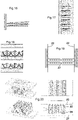
- Figure 11 shows an example of fin structures that corresponds to the example of figures 9 and 10 just the other way around.
- FIG. 12 shows on the left said first unit with the smooth plates and on the right the second unit, which (can be, but here) is not intended for receiving a part to be cooled, having a double-sided corrugated structure.
- the fins of the first and second unit are abutting at least such that the form an inbound channel 17.
- the channel 17 is at least formed in the area of the second unit fin front, i.e. shortly before the coolant is entering the root area to impinge on the first unit wall.
- Figure 14 shows an example how the fins are abutting and how the coolant is redirected.
- the reverse channels 18 are in this case also starting right at the second unit fronts where the first unit fins are abutting. It would be possible to keep some distance for the reverse flow such that no reverse "channels" are formed but a reverse flow (see Figure 18 ).
- the inbound coolant which is formed by channels in order to impinge on the root area in the form of a jet that will split up or broaden or swirl after it impinged on the root.
- the reverse flow is immediately introduced in reverse channels 18 which are arranged offset to the inbound channels 17.
- This channel offset O2 is to be understood with reference to an axis which is aligned perpendicular to the channels and parallel to the fins.
- Figure 15 shows a similar constellation, wherein only the first unit 19 has double-sided structured fins and the second unit has plain fins and a second surface for receiving electronics to cool.
- Figure 16 shows in an exaggerated sketch that the fins of the first unit have an inclination relative to the fins of the second unit. This is shown with the example of each of the units having double-sidedly structured fins, however other structure constellations may be applicable.
- Figure 17 shows this inclination with a side view of intertwining fins.
- the inbound channels are only formed shortly before the coolant hits the impingement zone (root) at the respective root.
- the coolant is not introduced into a reverse channel.
- the inbound channels forming little jets that can impinge on the root still leads to an advantageous cooling effect according to the invention.
- the coolant is whirled around generating turbulences.
- Figure 18 shows how the reverse flow is entering an open duct instead of the offset channels as known from the other embodiments.
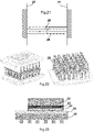
- Figures 19 and the four parts of figure 20 show an embodiment with a first unit 21, a second unit 22, and a third unit 23.
- the second unit is in this case an insert 22 having a both-sidedly corrugated structure.
- As second unit 22 counts every structured fin that is inserted into the cavities (so not only the one labelled in figure 19 , but the whole set).
- This set of fins 22 can be clamped between the first and second unit 21, 23.
- said assemblies 21, 23 may have shoulders 24 for the fronts of the second unit to abut.
- other means such as notches on the fins of the second unit 22 could also be another embodiment for fixating the second unit 22 in the assembly.
- the waved fins keep a gap to the roots such that the coolant can flow through the construction as indicated in the lower right part of figure 20 .
- the coolant is fed between the first unit 21 and the third unit 23 and splits up into the shown two opposing directions towards the first unit first root and the third unit first root.
- the second unit 22 fins abutting the fins of the first and third unit forms channels in which the coolant is flowing. After impinging on the respective root it flows back on the other side of the second unit fin where channels are formed, too.
- the coolant now confronting it distributes to the next "floor” or "storey", i.e. it flows around the second fins of the first and third unit, where the second unit second fin is again forming inbound channels.
- This embodiment is also relatively simple to machine while still providing the inventive principle.
- a plastic injection moulding part can be used since it does not need to necessarily have a good thermal conductivity and its purpose is mainly to form the inbound channels and the reverse channels offset to the inbound channels.
- FIG. 21 Another embodiment is shown with figures 21 and 22 , where a second unit 26 is a set of corrugated sheets each having a bend in the middle.
- the first unit 25 and the third unit 27 are similar to the ones from the embodiment of figures 19 and 20 , i.e. ribbed aluminium parts, with the difference that they are arranged offset relative to each other such that the fins can each rest on one of said bends in the second unit fins.
- a part to be cooled can be applied with the following configuration.
- the heatsink can be coated with thermally sprayed ceramic as electrical insulation. Between the ceramic layer and the heatsink, an intermediate layer can be applied to relieve the thermal stresses.
- the first unit 29 has on the opposite site of the roots (where the cooling impingement takes place) the surface to receive the part to be cooled 33.
- Said surface may have a coating 30 which is flame-sprayed and only 100 - 300 micrometer thin.
- coating is made of Al 2 O 3 or AIN.
- Intermediate layer 31 is optional and can consist of a cooper-based material.
- Thermal conductive layer 32 can for example be a glue, paste, or wax which is thermally conductive. This solution avoids the manufacturing step of soldering and allows for lesser interfaces compared to solutions known in the art.
- the invention relates to the following subject matters:
Landscapes
- Engineering & Computer Science (AREA)
- Microelectronics & Electronic Packaging (AREA)
- Physics & Mathematics (AREA)
- Thermal Sciences (AREA)
- Cooling Or The Like Of Semiconductors Or Solid State Devices (AREA)
- Cooling Or The Like Of Electrical Apparatus (AREA)
- Heat-Exchange Devices With Radiators And Conduit Assemblies (AREA)
Priority Applications (2)
| Application Number | Priority Date | Filing Date | Title |
|---|---|---|---|
| EP22177689.1A EP4080562B8 (de) | 2019-07-30 | 2019-07-30 | Kühler |
| ES22177689T ES3032953T3 (en) | 2019-07-30 | 2019-07-30 | Cooler |
Applications Claiming Priority (2)
| Application Number | Priority Date | Filing Date | Title |
|---|---|---|---|
| EP22177689.1A EP4080562B8 (de) | 2019-07-30 | 2019-07-30 | Kühler |
| EP19189127.4A EP3772095B1 (de) | 2019-07-30 | 2019-07-30 | Kühler |
Related Parent Applications (1)
| Application Number | Title | Priority Date | Filing Date |
|---|---|---|---|
| EP19189127.4A Division EP3772095B1 (de) | 2019-07-30 | 2019-07-30 | Kühler |
Publications (4)
| Publication Number | Publication Date |
|---|---|
| EP4080562A2 true EP4080562A2 (de) | 2022-10-26 |
| EP4080562A3 EP4080562A3 (de) | 2023-03-08 |
| EP4080562B1 EP4080562B1 (de) | 2025-03-19 |
| EP4080562B8 EP4080562B8 (de) | 2025-04-23 |
Family
ID=67544003
Family Applications (2)
| Application Number | Title | Priority Date | Filing Date |
|---|---|---|---|
| EP19189127.4A Active EP3772095B1 (de) | 2019-07-30 | 2019-07-30 | Kühler |
| EP22177689.1A Active EP4080562B8 (de) | 2019-07-30 | 2019-07-30 | Kühler |
Family Applications Before (1)
| Application Number | Title | Priority Date | Filing Date |
|---|---|---|---|
| EP19189127.4A Active EP3772095B1 (de) | 2019-07-30 | 2019-07-30 | Kühler |
Country Status (3)
| Country | Link |
|---|---|
| EP (2) | EP3772095B1 (de) |
| CN (1) | CN112312732B (de) |
| ES (1) | ES3032953T3 (de) |
Citations (1)
| Publication number | Priority date | Publication date | Assignee | Title |
|---|---|---|---|---|
| EP2291859A1 (de) | 2008-06-18 | 2011-03-09 | Brusa Elektronik AG | Kühlsystem, insbesondere für elektronische struktureinheiten |
Family Cites Families (7)
| Publication number | Priority date | Publication date | Assignee | Title |
|---|---|---|---|---|
| US7509995B2 (en) * | 2004-05-06 | 2009-03-31 | Delphi Technologies, Inc. | Heat dissipation element for cooling electronic devices |
| US7588074B1 (en) * | 2004-12-21 | 2009-09-15 | Robert Alvin White | In the rate of energy transfer across boundaries |
| JP5542765B2 (ja) * | 2011-09-26 | 2014-07-09 | 日立オートモティブシステムズ株式会社 | パワーモジュール |
| JP5880531B2 (ja) * | 2013-12-11 | 2016-03-09 | トヨタ自動車株式会社 | 冷却器 |
| DE102015112031B4 (de) * | 2015-07-23 | 2017-08-17 | Halla Visteon Climate Control Corporation | Anordnung zur Verbesserung einer Strombelastbarkeit von Leiterbahnen |
| CN105514064A (zh) * | 2016-01-25 | 2016-04-20 | 中国电子科技集团公司第三十八研究所 | 散热器 |
| JP6735664B2 (ja) * | 2016-12-28 | 2020-08-05 | 昭和電工株式会社 | 液冷式冷却装置用放熱器およびその製造方法 |
-
2019
- 2019-07-30 EP EP19189127.4A patent/EP3772095B1/de active Active
- 2019-07-30 EP EP22177689.1A patent/EP4080562B8/de active Active
- 2019-07-30 ES ES22177689T patent/ES3032953T3/es active Active
-
2020
- 2020-07-24 CN CN202010722007.XA patent/CN112312732B/zh active Active
Patent Citations (1)
| Publication number | Priority date | Publication date | Assignee | Title |
|---|---|---|---|---|
| EP2291859A1 (de) | 2008-06-18 | 2011-03-09 | Brusa Elektronik AG | Kühlsystem, insbesondere für elektronische struktureinheiten |
Also Published As
| Publication number | Publication date |
|---|---|
| EP4080562A3 (de) | 2023-03-08 |
| CN112312732B (zh) | 2025-08-29 |
| EP3772095A1 (de) | 2021-02-03 |
| ES3032953T3 (en) | 2025-07-29 |
| EP3772095B1 (de) | 2022-06-08 |
| EP4080562B8 (de) | 2025-04-23 |
| CN112312732A (zh) | 2021-02-02 |
| EP4080562B1 (de) | 2025-03-19 |
Similar Documents
| Publication | Publication Date | Title |
|---|---|---|
| EP2291859B1 (de) | Kühlsystem, insbesondere für elektronische struktureinheiten | |
| US6308771B1 (en) | High performance fan tail heat exchanger | |
| US5304845A (en) | Apparatus for an air impingement heat sink using secondary flow generators | |
| US11644253B2 (en) | Cooler and cooler body | |
| US7536870B2 (en) | High power microjet cooler | |
| CN112020629B (zh) | 用于冷却热源组件的至少两个不同的第一发热元件的流体基冷却装置 | |
| CN112969340B (zh) | 电子元件的散热装置和电子设备 | |
| TWI835709B (zh) | 層壓的微通道熱交換器 | |
| US20240130077A1 (en) | Multichannel manifold cold plate | |
| CN114615866B (zh) | 液冷板及电子设备 | |
| CN111699554B (zh) | 冷却器和半导体模块 | |
| JP6157887B2 (ja) | 冷却装置 | |
| EP3772095B1 (de) | Kühler | |
| CN109416224A (zh) | 层压微通道热交换器 | |
| JP2014045134A (ja) | 流路部材およびこれを用いた熱交換器ならびに半導体装置 | |
| JP7734526B2 (ja) | 冷却装置 | |
| WO2026012079A1 (zh) | 冷板、服务器及服务器系统 | |
| TW202239302A (zh) | 液冷散熱結構 | |
| CN116761400A (zh) | 一种分体式液冷板 | |
| JP2011171686A (ja) | 放熱部付き金属ベースプリント基板 | |
| EP3772096B1 (de) | Kühlerkörper | |
| CN112930097A (zh) | 散热装置及空调 | |
| JP4522725B2 (ja) | ヒートシンク | |
| JP7002384B2 (ja) | 冷却装置及びそれを備える電気機器 | |
| CN220915631U (zh) | 电子器件及其模块化结构、通讯电源 |
Legal Events
| Date | Code | Title | Description |
|---|---|---|---|
| PUAI | Public reference made under article 153(3) epc to a published international application that has entered the european phase |
Free format text: ORIGINAL CODE: 0009012 |
|
| STAA | Information on the status of an ep patent application or granted ep patent |
Free format text: STATUS: THE APPLICATION HAS BEEN PUBLISHED |
|
| AC | Divisional application: reference to earlier application |
Ref document number: 3772095 Country of ref document: EP Kind code of ref document: P |
|
| AK | Designated contracting states |
Kind code of ref document: A2 Designated state(s): AL AT BE BG CH CY CZ DE DK EE ES FI FR GB GR HR HU IE IS IT LI LT LU LV MC MK MT NL NO PL PT RO RS SE SI SK SM TR |
|
| PUAL | Search report despatched |
Free format text: ORIGINAL CODE: 0009013 |
|
| AK | Designated contracting states |
Kind code of ref document: A3 Designated state(s): AL AT BE BG CH CY CZ DE DK EE ES FI FR GB GR HR HU IE IS IT LI LT LU LV MC MK MT NL NO PL PT RO RS SE SI SK SM TR |
|
| RIC1 | Information provided on ipc code assigned before grant |
Ipc: H01L 23/373 20060101ALI20230131BHEP Ipc: H01L 23/473 20060101AFI20230131BHEP |
|
| STAA | Information on the status of an ep patent application or granted ep patent |
Free format text: STATUS: REQUEST FOR EXAMINATION WAS MADE |
|
| 17P | Request for examination filed |
Effective date: 20230907 |
|
| RBV | Designated contracting states (corrected) |
Designated state(s): AL AT BE BG CH CY CZ DE DK EE ES FI FR GB GR HR HU IE IS IT LI LT LU LV MC MK MT NL NO PL PT RO RS SE SI SK SM TR |
|
| GRAP | Despatch of communication of intention to grant a patent |
Free format text: ORIGINAL CODE: EPIDOSNIGR1 |
|
| STAA | Information on the status of an ep patent application or granted ep patent |
Free format text: STATUS: GRANT OF PATENT IS INTENDED |
|
| INTG | Intention to grant announced |
Effective date: 20241009 |
|
| GRAS | Grant fee paid |
Free format text: ORIGINAL CODE: EPIDOSNIGR3 |
|
| GRAA | (expected) grant |
Free format text: ORIGINAL CODE: 0009210 |
|
| STAA | Information on the status of an ep patent application or granted ep patent |
Free format text: STATUS: THE PATENT HAS BEEN GRANTED |
|
| REG | Reference to a national code |
Ref country code: DE Ref legal event code: R081 Ref document number: 602019067657 Country of ref document: DE Owner name: BRUSA HYPOWER AG, CH Free format text: FORMER OWNER: BRUSA TECHNOLOGY AG, BUCHS, CH |
|
| AC | Divisional application: reference to earlier application |
Ref document number: 3772095 Country of ref document: EP Kind code of ref document: P |
|
| AK | Designated contracting states |
Kind code of ref document: B1 Designated state(s): AL AT BE BG CH CY CZ DE DK EE ES FI FR GB GR HR HU IE IS IT LI LT LU LV MC MK MT NL NO PL PT RO RS SE SI SK SM TR |
|
| REG | Reference to a national code |
Ref country code: GB Ref legal event code: FG4D |
|
| REG | Reference to a national code |
Ref country code: CH Ref legal event code: PK Free format text: BERICHTIGUNG B8 Ref country code: CH Ref legal event code: EP |
|
| RAP2 | Party data changed (patent owner data changed or rights of a patent transferred) |
Owner name: BRUSA HYPOWER AG |
|
| REG | Reference to a national code |
Ref country code: IE Ref legal event code: FG4D |
|
| REG | Reference to a national code |
Ref country code: DE Ref legal event code: R096 Ref document number: 602019067657 Country of ref document: DE |
|
| PG25 | Lapsed in a contracting state [announced via postgrant information from national office to epo] |
Ref country code: RS Free format text: LAPSE BECAUSE OF FAILURE TO SUBMIT A TRANSLATION OF THE DESCRIPTION OR TO PAY THE FEE WITHIN THE PRESCRIBED TIME-LIMIT Effective date: 20250619 |
|
| PG25 | Lapsed in a contracting state [announced via postgrant information from national office to epo] |
Ref country code: FI Free format text: LAPSE BECAUSE OF FAILURE TO SUBMIT A TRANSLATION OF THE DESCRIPTION OR TO PAY THE FEE WITHIN THE PRESCRIBED TIME-LIMIT Effective date: 20250319 |
|
| REG | Reference to a national code |
Ref country code: LT Ref legal event code: MG9D |
|
| PG25 | Lapsed in a contracting state [announced via postgrant information from national office to epo] |
Ref country code: NO Free format text: LAPSE BECAUSE OF FAILURE TO SUBMIT A TRANSLATION OF THE DESCRIPTION OR TO PAY THE FEE WITHIN THE PRESCRIBED TIME-LIMIT Effective date: 20250619 |
|
| PG25 | Lapsed in a contracting state [announced via postgrant information from national office to epo] |
Ref country code: HR Free format text: LAPSE BECAUSE OF FAILURE TO SUBMIT A TRANSLATION OF THE DESCRIPTION OR TO PAY THE FEE WITHIN THE PRESCRIBED TIME-LIMIT Effective date: 20250319 |
|
| PG25 | Lapsed in a contracting state [announced via postgrant information from national office to epo] |
Ref country code: LV Free format text: LAPSE BECAUSE OF FAILURE TO SUBMIT A TRANSLATION OF THE DESCRIPTION OR TO PAY THE FEE WITHIN THE PRESCRIBED TIME-LIMIT Effective date: 20250319 |
|
| PG25 | Lapsed in a contracting state [announced via postgrant information from national office to epo] |
Ref country code: GR Free format text: LAPSE BECAUSE OF FAILURE TO SUBMIT A TRANSLATION OF THE DESCRIPTION OR TO PAY THE FEE WITHIN THE PRESCRIBED TIME-LIMIT Effective date: 20250620 Ref country code: BG Free format text: LAPSE BECAUSE OF FAILURE TO SUBMIT A TRANSLATION OF THE DESCRIPTION OR TO PAY THE FEE WITHIN THE PRESCRIBED TIME-LIMIT Effective date: 20250319 |
|
| REG | Reference to a national code |
Ref country code: NL Ref legal event code: MP Effective date: 20250319 |
|
| REG | Reference to a national code |
Ref country code: ES Ref legal event code: FG2A Ref document number: 3032953 Country of ref document: ES Kind code of ref document: T3 Effective date: 20250729 |
|
| REG | Reference to a national code |
Ref country code: AT Ref legal event code: MK05 Ref document number: 1777715 Country of ref document: AT Kind code of ref document: T Effective date: 20250319 |
|
| PG25 | Lapsed in a contracting state [announced via postgrant information from national office to epo] |
Ref country code: NL Free format text: LAPSE BECAUSE OF FAILURE TO SUBMIT A TRANSLATION OF THE DESCRIPTION OR TO PAY THE FEE WITHIN THE PRESCRIBED TIME-LIMIT Effective date: 20250319 |
|
| PG25 | Lapsed in a contracting state [announced via postgrant information from national office to epo] |
Ref country code: SE Free format text: LAPSE BECAUSE OF FAILURE TO SUBMIT A TRANSLATION OF THE DESCRIPTION OR TO PAY THE FEE WITHIN THE PRESCRIBED TIME-LIMIT Effective date: 20250319 |
|
| PG25 | Lapsed in a contracting state [announced via postgrant information from national office to epo] |
Ref country code: SM Free format text: LAPSE BECAUSE OF FAILURE TO SUBMIT A TRANSLATION OF THE DESCRIPTION OR TO PAY THE FEE WITHIN THE PRESCRIBED TIME-LIMIT Effective date: 20250319 |
|
| PG25 | Lapsed in a contracting state [announced via postgrant information from national office to epo] |
Ref country code: PT Free format text: LAPSE BECAUSE OF FAILURE TO SUBMIT A TRANSLATION OF THE DESCRIPTION OR TO PAY THE FEE WITHIN THE PRESCRIBED TIME-LIMIT Effective date: 20250721 |
|
| PGFP | Annual fee paid to national office [announced via postgrant information from national office to epo] |
Ref country code: ES Payment date: 20250819 Year of fee payment: 7 |
|
| PGFP | Annual fee paid to national office [announced via postgrant information from national office to epo] |
Ref country code: DE Payment date: 20250723 Year of fee payment: 7 |
|
| PG25 | Lapsed in a contracting state [announced via postgrant information from national office to epo] |
Ref country code: PL Free format text: LAPSE BECAUSE OF FAILURE TO SUBMIT A TRANSLATION OF THE DESCRIPTION OR TO PAY THE FEE WITHIN THE PRESCRIBED TIME-LIMIT Effective date: 20250319 |
|
| PGFP | Annual fee paid to national office [announced via postgrant information from national office to epo] |
Ref country code: IT Payment date: 20250731 Year of fee payment: 7 Ref country code: TR Payment date: 20250725 Year of fee payment: 7 |
|
| PGFP | Annual fee paid to national office [announced via postgrant information from national office to epo] |
Ref country code: GB Payment date: 20250724 Year of fee payment: 7 |
|
| PG25 | Lapsed in a contracting state [announced via postgrant information from national office to epo] |
Ref country code: AT Free format text: LAPSE BECAUSE OF FAILURE TO SUBMIT A TRANSLATION OF THE DESCRIPTION OR TO PAY THE FEE WITHIN THE PRESCRIBED TIME-LIMIT Effective date: 20250319 |
|
| PGFP | Annual fee paid to national office [announced via postgrant information from national office to epo] |
Ref country code: FR Payment date: 20250718 Year of fee payment: 7 |
|
| PG25 | Lapsed in a contracting state [announced via postgrant information from national office to epo] |
Ref country code: CZ Free format text: LAPSE BECAUSE OF FAILURE TO SUBMIT A TRANSLATION OF THE DESCRIPTION OR TO PAY THE FEE WITHIN THE PRESCRIBED TIME-LIMIT Effective date: 20250319 |
|
| PG25 | Lapsed in a contracting state [announced via postgrant information from national office to epo] |
Ref country code: RO Free format text: LAPSE BECAUSE OF FAILURE TO SUBMIT A TRANSLATION OF THE DESCRIPTION OR TO PAY THE FEE WITHIN THE PRESCRIBED TIME-LIMIT Effective date: 20250319 |
|
| PG25 | Lapsed in a contracting state [announced via postgrant information from national office to epo] |
Ref country code: SK Free format text: LAPSE BECAUSE OF FAILURE TO SUBMIT A TRANSLATION OF THE DESCRIPTION OR TO PAY THE FEE WITHIN THE PRESCRIBED TIME-LIMIT Effective date: 20250319 |
|
| PG25 | Lapsed in a contracting state [announced via postgrant information from national office to epo] |
Ref country code: IS Free format text: LAPSE BECAUSE OF FAILURE TO SUBMIT A TRANSLATION OF THE DESCRIPTION OR TO PAY THE FEE WITHIN THE PRESCRIBED TIME-LIMIT Effective date: 20250719 |
|
| REG | Reference to a national code |
Ref country code: DE Ref legal event code: R079 Ref document number: 602019067657 Country of ref document: DE Free format text: PREVIOUS MAIN CLASS: H01L0023473000 Ipc: H10W0040470000 |
|
| REG | Reference to a national code |
Ref country code: DE Ref legal event code: R097 Ref document number: 602019067657 Country of ref document: DE |
|
| PG25 | Lapsed in a contracting state [announced via postgrant information from national office to epo] |
Ref country code: DK Free format text: LAPSE BECAUSE OF FAILURE TO SUBMIT A TRANSLATION OF THE DESCRIPTION OR TO PAY THE FEE WITHIN THE PRESCRIBED TIME-LIMIT Effective date: 20250319 |
|
| PLBE | No opposition filed within time limit |
Free format text: ORIGINAL CODE: 0009261 |
|
| STAA | Information on the status of an ep patent application or granted ep patent |
Free format text: STATUS: NO OPPOSITION FILED WITHIN TIME LIMIT |
|
| REG | Reference to a national code |
Ref country code: CH Ref legal event code: L10 Free format text: ST27 STATUS EVENT CODE: U-0-0-L10-L00 (AS PROVIDED BY THE NATIONAL OFFICE) Effective date: 20260128 |