EP4080176B1 - Balance dotée d'une plateforme de mesure portée par des pieds supports - Google Patents
Balance dotée d'une plateforme de mesure portée par des pieds supports Download PDFInfo
- Publication number
- EP4080176B1 EP4080176B1 EP21169148.0A EP21169148A EP4080176B1 EP 4080176 B1 EP4080176 B1 EP 4080176B1 EP 21169148 A EP21169148 A EP 21169148A EP 4080176 B1 EP4080176 B1 EP 4080176B1
- Authority
- EP
- European Patent Office
- Prior art keywords
- foot
- measuring
- load cell
- weighing scale
- scale according
- Prior art date
- Legal status (The legal status is an assumption and is not a legal conclusion. Google has not performed a legal analysis and makes no representation as to the accuracy of the status listed.)
- Active
Links
- 238000005303 weighing Methods 0.000 claims description 18
- 238000013016 damping Methods 0.000 claims 7
- 239000004020 conductor Substances 0.000 claims 2
- 230000000284 resting effect Effects 0.000 claims 2
- 238000000034 method Methods 0.000 description 2
- 239000000853 adhesive Substances 0.000 description 1
- 230000001070 adhesive effect Effects 0.000 description 1
- 238000005452 bending Methods 0.000 description 1
- 230000005540 biological transmission Effects 0.000 description 1
- 238000010276 construction Methods 0.000 description 1
- 230000001419 dependent effect Effects 0.000 description 1
- 230000001627 detrimental effect Effects 0.000 description 1
- 238000006073 displacement reaction Methods 0.000 description 1
- 230000005484 gravity Effects 0.000 description 1
- 230000005570 vertical transmission Effects 0.000 description 1
Images


Classifications
-
- G—PHYSICS
- G01—MEASURING; TESTING
- G01G—WEIGHING
- G01G21/00—Details of weighing apparatus
- G01G21/23—Support or suspension of weighing platforms
-
- G—PHYSICS
- G01—MEASURING; TESTING
- G01G—WEIGHING
- G01G21/00—Details of weighing apparatus
- G01G21/28—Frames, Housings
-
- G—PHYSICS
- G01—MEASURING; TESTING
- G01G—WEIGHING
- G01G23/00—Auxiliary devices for weighing apparatus
- G01G23/06—Means for damping oscillations, e.g. of weigh beams
-
- G—PHYSICS
- G01—MEASURING; TESTING
- G01G—WEIGHING
- G01G21/00—Details of weighing apparatus
- G01G21/22—Weigh pans or other weighing receptacles; Weighing platforms
Definitions
- the present invention relates to a scale with a measuring platform that is supported by at least three feet that are supported on the floor, with each foot being assigned a load cell that records the portion of the weight force emanating from the measuring platform that falls on the foot.
- Such scales are used as personal scales or other scales for weighing objects.
- a vertical direction refers to the direction of the earth's gravity and to a position of the scale in which the scale is in an operative position on a level horizontal floor supporting it.
- U.S. 2004/0035610 A1 discloses a scale having the features of the preamble of claim 1 .
- a typical other known scale has the following structure, on which the preamble of claim 1 is based.
- the scale has a stable, rectangular support frame below its measuring platform. In the corner areas of the support frame, there are mounted supports which run horizontally outwards and which each carry a load cell on their upper side facing the underside of the measuring platform.
- Each horizontal support is provided with a base which protrudes vertically downwards from its lower side facing away from the measuring platform and which is offset outwards in the horizontal direction in relation to the load cell.
- Each foot is rotatably mounted in a thread on the associated horizontal support so that the height of the foot on the horizontal support can be adjusted by rotating the foot.
- a very similar scale is in DE 10 2008 062 249 described, in which case the load cell itself has a horizontal extension and is designed as a bending beam, which is screwed to the measuring platform at one end and a leg is screwed into the opposite end.
- the structure described has several disadvantages.
- the feet including their height-adjustable storage, are arranged vertically on the supports at a lower level below the load cells, so that their vertical heights add up to a total vertical height.
- considerable leverage forces are generated, which are generated by the distance between the introduction of force into the load cell and the transmission via the horizontal support in the base. These leverage forces can cause deflection of the horizontal beams and affect the accuracy of the scale.
- each foot is designed as a measuring foot, in that the associated load cell is integrated into the measuring foot in the manner defined in claim 1 .
- each base is designed as a vertically running measuring base with: a load cell support which is held non-rotatably with respect to the measuring platform and on which the load cell rests and is fixed and which has an external thread, and with an adjustable foot located under the load cell support.
- the adjustable foot is designed with a circular-cylindrical recess that is open at the top and is provided on its lateral circumference with an internal thread that matches the external thread of the load cell carrier. The external thread of the load cell carrier is screwed into the internal thread of the adjustable foot, so that the height of the measuring foot can be adjusted along the screw axis by rotating the adjustable foot relative to the load cell carrier.
- a low overall height of the scale can be achieved because the height adjustment mechanism can at least partially overlap with the load cell carrier and the load cell in the vertical direction, whereas in the prior art the height-adjustable stand and the load cell carrier were necessarily arranged vertically offset from one another, as in described in the introduction.
- each measuring foot is assigned a buffer support element that is vertically between of the measuring platform and the load cell at the top of the measuring foot and which is supported in the middle and centered on the sensitive area of the load cell, so that the force flow from the measuring platform occurs vertically through the buffer support element into the load cell at the top of the measuring foot.
- the buffer support member can be made of rubber as a rubber buffer.
- the buffer support member may have any shape, such as a circular cylinder, a prism, a disc, a parallelepiped, etc. shape.
- the load cell is preferably mounted centered in the load cell carrier in each measuring foot and the load cell carrier is screwed centered in the adjustable foot, so that the force flow from the measuring platform occurs vertically through each measuring foot.
- each buffer support element is designed in the form of a truncated cone, with the larger end face of the frustoconical buffer support element bearing against the underside of the measuring platform and the frustoconical buffer support element being supported on the load cell via the smaller end surface.
- each measuring foot is also provided with a device foot plate at the lower end, which is firmly connected to the adjustable foot on the side facing away from the measuring platform and which is designed to introduce the weight force transmitted by the measuring foot into the ground.
- the device base plate can be detachably or permanently connected to the adjustable foot.
- an adapter housing can be provided for accommodating or attaching non-weight-sensitive additional components; non-weight-sensitive additional components are components that should not be weighed. Such non-weight-sensitive additional components must placed or attached to a non-weight-sensitive area of the balance, such as the adapter housing, so that they do not affect the weighing process.
- the adapter housing has a vertical passage.
- the adjustable foot which is not connected to the adapter housing and is therefore freely rotatable in the passage, runs through the passage of the adapter housing.
- the base plate of the device protrudes beyond the opening of the passage of the adapter housing, so that the adapter housing cannot become detached from the adjustable foot.
- the four measuring feet can be arranged at the corners of a square.
- the measuring feet can be connected to form a measuring foot assembly, in that two frame parts emanate from each measuring foot and connect the measuring foot to the two next-neighboring measuring feet.
- the frame parts are connected to the measuring feet and are therefore not part of the weighing-sensitive area, i.e. their weight does not affect the load cells.
- electrical lines connected to the load cells can be routed in or on the frame parts. It should be noted that this frame has no load-bearing function.
- a socket is preferably attached to at least one frame part, which socket is connected to a line running in the frame part and which is used to connect an external plug of a line.
- Several sockets can also be integrated in one connection unit.
- the sockets can include USB, network sockets and sockets for connecting a power supply. The advantage of these embodiments is that a line connected to the socket is connected in the non-weight-sensitive area and therefore has no influence on the weighing result with its weight.
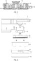
- FIG. 1 shows an embodiment of the scales in a perspective view, wherein a measuring platform 2 of the scales is shown detached and lifted from a measuring foot assembly 4 located underneath.
- the measuring foot assembly 4 comprises four measuring feet 8 which are arranged at the corners of a square and are connected to one another by frame parts 6 .
- the structure of a single measuring foot 8 is described below with reference to the figures 2 to 4 described, which the measuring foot in 2 and Fig. 4 in exploded view and in 3 show in section.
- the measuring foot includes a load cell 10, the top of which is exposed at the top of the measuring foot.
- the load cell 10 is accommodated and fastened in a load cell carrier 16 .
- the load cell support 16 is generally cup-shaped with an upwardly open receiving space configured to receive the load cell 10 centered, and has a circular cylindrical shape outer wall.
- the load cell 10 is fastened in the load cell carrier 16, for example by means of screws.
- the top of the load cell remains freely accessible in the load cell carrier 16, which is open at the top.
- the cylindrical outer wall of the cup-shaped load cell carrier 16 is provided with an external thread 18 .
- an adjustable foot 20 which is also essentially cup-shaped and has a central, cylindrical recess 22 .
- the inner wall of the cylindrical recess 22 is provided with an internal thread 24 which matches the external thread 18 of the load cell carrier 16 .
- the external thread 18 of the load cell carrier 16 is screwed into the internal thread 24 of the adjustable foot 20 .
- the load cell carrier 16 is held in a rotationally fixed manner in relation to the measuring platform 2 so that it cannot rotate with the adjustable foot 20 .
- This non-rotatable connection is realized, for example, in the following way.
- the measuring platform 2 rests on the load cell 10 via a buffer support element 12 .
- the rubber buffer support element 12 has the shape of a truncated cone, with the larger end face of the buffer support element 12 being connected to the underside of the measuring platform, for example by means of an adhesive connection to the underside of the measuring platform 2
- the frusto-conical bumper support member 12 has a set screw 14 received therein which protrudes centrally from the minor face of the bumper support member 14 .
- the threaded pin 14 protrudes downward beyond the load cell 10 through a passage in the load cell 10 .
- a nut is screwed onto the end of the threaded pin 14 protruding beyond the load cell 10 and is tightened in order to create a frictional connection with the buffer support element 12 and thus with the measuring platform 2 .
- each adjustable foot 16 to two frame parts 6 extending therefrom (see 1 and Fig. 4), wherein one end of the frame part 6 comes to rest on the edge of the load cell carrier 16 and is screwed tightly thereto.
- FIG. 4 in which a screw is shown above the end of the frame part 6, which is screwed into a thread provided for this purpose in the outer wall of the load cell carrier 16 after the end of the frame part 6 has been lowered onto the edge of the load cell carrier 16.
- two screws are provided for each frame part 6, which fasten the end of the frame part 6 to the edge of the load cell carrier 16.
- An adapter housing 30 is optionally attached to the adjustable foot 20 .
- the adapter housing 30 has an annular section with a cylindrical passage 32 through which the adjustable foot 20 runs.
- the adapter housing 30 is not directly connected to the adjustable foot 20 so that the latter can be rotated freely in the passage 32 of the adapter housing 30 . Additional components that are not relevant to the weighing process can be kept ready in the areas of the adapter housing 30 that are radially outside of the passage 32 .
- a device foot plate 40 or device base plate 40 which is firmly connected with its flat central area to the flat floor on the underside of the adjustable foot 20 .
- the device base plate 40 serves to introduce the weight force transmitted by the respective measuring foot 8 into the floor on which the scale is standing.
- a user can individually adjust the height of each measuring foot 8 by rotating his device foot plate 40 .
- the rotation of the base plate 40 is transmitted directly to the fixed foot 20 connected thereto, which thereby rotates relative to the load cell carrier 16 and thereby adjusts the vertical expansion of the combination of the adjustable foot 20 and the load cell carrier 16 .
- the load cell carrier 16 is held non-rotatably relative to the measuring platform 2 and therefore cannot rotate with the adjustable foot 20 when the height of the measuring foot 8 is adjusted.
- the described design of the feet of the scale as measuring feet 8 enables a low vertical height of the scale, since the height-adjustable components of the foot (load cell carrier 16 and adjustable foot 20) overlap to a greater or lesser extent in the vertical direction, depending on the extent to which the load cell carrier 16 in the Adjustable foot 20 is screwed in or out.
- the load cell carrier with the load cell was located vertically completely above the height-adjustable base, so that their overall heights always added up to the full extent, resulting in a greater overall height.
- a further advantage of the described construction of the measuring feet 8 is that the weight force falling on each measuring foot 8 is transmitted purely vertically and centered through the measuring foot 8 into the ground.
- the weight force is transmitted from the measuring platform 2 by the buffer support element 12 centered on the load cell 10, and further vertically and centered by the load cell carrier, which is mounted centered in the adjustable foot 20, so that the adjustable foot 20 finally introduces the weight force vertically via the device base plate 40 into the floor on which the scale is standing.
Landscapes
- Physics & Mathematics (AREA)
- General Physics & Mathematics (AREA)
- Measurement Of Force In General (AREA)
- Measurement Of The Respiration, Hearing Ability, Form, And Blood Characteristics Of Living Organisms (AREA)
Claims (12)
- Balance avec une plate-forme de mesure (2), qui est supportée par au moins trois pieds s'appuyant contre le sol, dans lequel, à chaque, correspond une cellule de pesage qui mesure la part exercée sur le pied du poids exercé par la plate-forme de mesure (2), et chaque pied est conçu comme un pied de mesure (8) s'étendant verticalement, caractérisé en ce que le pied de mesure (8) :un support de cellule de pesage (16), sur lequel repose et est fixée la cellule de pesage (10) et qui est muni d'un filetage externe (18), dans lequel le support de cellule de pesage (16) est maintenu de manière solidaire en rotation par rapport à la plate-forme de mesure etcomprend un pied de réglage (20) se trouvant en dessous du support de cellule de pesage (16), qui est conçu pour le logement d'au moins une partie verticale du support de cellule de pesage (16) avec un évidement cylindrique ouvert en haut (22), qui est muni, sur sa périphérie latérale, d'un filetage interne (24) adapté au filetage externe (18) du support de cellule de pesage (16), dans lequel le support de cellule de pesage (16) est vissé, avec son filetage externe (18), dans le filetage interne (24) du pied de réglage (20), de façon à ce qu'une rotation du pied de réglage (20) par rapport au support de cellule de pesage (16), permette de régler le pied de mesure (8) en hauteur le long de l'axe de vissage.
- Balance selon la revendication 1, caractérisée en ce que, à chaque pied de mesure (8), correspond un élément d'appui tampon (12) qui est disposé de façon à s'étendre verticalement entre la plate-forme de mesure (2) et le pied de mesure (8) correspond et s'appuie au milieu et de manière centrée sur la cellule de pesage (10) en haut du pied de mesure (8), de façon à ce que le flux de force parte de la plate-forme de mesure (2) et traverse l'élément d'appui tampon (12) vers le pied de mesure (8).
- Balance selon la revendication 2, caractérisée en ce que les éléments d'appui tampons (12) sont constitués de caoutchouc.
- Balance selon la revendication 2 ou 3, caractérisée en ce que, dans chaque pied de mesure (8), la cellule de pesage (10) est logée de manière centrée dans le support de cellule de pesage (16) et le support de cellule de pesage (16) est vissée de manière centrée dans le pied de réglage (20), de façon à ce que le flux de force aille de la plate-forme de mesure (2) verticalement à travers chaque pied de mesure (8).
- Balance selon l'une des revendications 2 à 4, caractérisée en ce que chaque élément d'appui tampon (12) présente une forme tronconique, dans lequel la face frontale la plus grande de l'élément d'appui tampon (12) tronconique s'appuie contre la face inférieure de la plate-forme de mesure (2) et l'élément d'appui tampon (12) tronconique s'appuie contre la cellule de pesage (10) par l'intermédiaire de la face frontale la plus petite.
- Balance selon l'une des revendications précédentes, caractérisée en ce que chaque pied de mesure (8) est en outre muni, à l'extrémité inférieure, d'une plaque de pied d'appareil (40) qui est reliée, sur le côté opposé à la plate-forme de mesure (2) du pied de réglage (20), fermement avec celui-ci et qui est conçue pou appliquer la force du poids transmise par le pied de mesure (8) dans le sol.
- Balance selon l'une des revendications précédentes, caractérisée en ce qu'un boîtier d'adaptateur (30) comprend, pour le logement de composants supplémentaires non sensibles au poids, un passage vertical (32), à travers lequel le pied de réglage (20) s'étend, qui n'est pas relié avec le boîtier d'adaptateur (30) et peut donc tourner librement dans le passage (32), dans lequel la plaque de pied d'appareil (40) dépasse hors de l'ouverture du passage (32) du boîtier d'adaptateur (40) afin d'empêcher ainsi que le boîtier d'adaptateur (30) se détache du pied de réglage.
- Balance selon l'une des revendications précédentes, caractérisée en ce que quatre pieds de mesure (8) supportent la plate-forme de mesure (2).
- Balance selon l'une des revendications précédentes, caractérisée en ce que les pieds de mesure (8) forment un ensemble de pieds de mesure (4) grâce au fait que chaque pied de mesure (8) est relié par deux parties de cadre (6) avec les pieds de mesure adjacents les plus proches.
- Balance selon la revendication 9, caractérisée en ce que dans ou sur les parties de cadre (6) sont guidés des câbles électriques reliés aux cellules de pesage (12).
- Balance selon la revendication 9 ou 10, caractérisée en ce que, sur au moins une des parties de cadre (6), est monté un connecteur d'enfichage, qui est relié avec un câble s'étendant dans la partie de cadre.
- Balance selon la revendication 11, caractérisée en ce que le connecteur d'enfichage est un connecteur USB, un connecteur réseau ou un connecteur d'alimentation de tension.
Priority Applications (4)
| Application Number | Priority Date | Filing Date | Title |
|---|---|---|---|
| EP21169148.0A EP4080176B1 (fr) | 2021-04-19 | 2021-04-19 | Balance dotée d'une plateforme de mesure portée par des pieds supports |
| JP2022053194A JP2022165393A (ja) | 2021-04-19 | 2022-03-29 | 支持脚によって支持された測定台を有する重量計 |
| CN202210407873.9A CN115219008A (zh) | 2021-04-19 | 2022-04-19 | 具有由支撑脚支撑的测量平台的称重秤 |
| US17/723,720 US20220333973A1 (en) | 2021-04-19 | 2022-04-19 | Weighing scale having a measuring platform supported by supporting feet |
Applications Claiming Priority (1)
| Application Number | Priority Date | Filing Date | Title |
|---|---|---|---|
| EP21169148.0A EP4080176B1 (fr) | 2021-04-19 | 2021-04-19 | Balance dotée d'une plateforme de mesure portée par des pieds supports |
Publications (2)
| Publication Number | Publication Date |
|---|---|
| EP4080176A1 EP4080176A1 (fr) | 2022-10-26 |
| EP4080176B1 true EP4080176B1 (fr) | 2023-06-28 |
Family
ID=75581467
Family Applications (1)
| Application Number | Title | Priority Date | Filing Date |
|---|---|---|---|
| EP21169148.0A Active EP4080176B1 (fr) | 2021-04-19 | 2021-04-19 | Balance dotée d'une plateforme de mesure portée par des pieds supports |
Country Status (4)
| Country | Link |
|---|---|
| US (1) | US20220333973A1 (fr) |
| EP (1) | EP4080176B1 (fr) |
| JP (1) | JP2022165393A (fr) |
| CN (1) | CN115219008A (fr) |
Family Cites Families (2)
| Publication number | Priority date | Publication date | Assignee | Title |
|---|---|---|---|---|
| US6838624B2 (en) * | 2002-08-22 | 2005-01-04 | Idt Technology Limited | Weighing scale |
| DE102008062249B4 (de) * | 2008-12-16 | 2013-08-14 | Hottinger Baldwin Messtechnik Gmbh | Standfuss für eine Wägezelle |
-
2021
- 2021-04-19 EP EP21169148.0A patent/EP4080176B1/fr active Active
-
2022
- 2022-03-29 JP JP2022053194A patent/JP2022165393A/ja active Pending
- 2022-04-19 CN CN202210407873.9A patent/CN115219008A/zh active Pending
- 2022-04-19 US US17/723,720 patent/US20220333973A1/en active Pending
Also Published As
| Publication number | Publication date |
|---|---|
| US20220333973A1 (en) | 2022-10-20 |
| JP2022165393A (ja) | 2022-10-31 |
| EP4080176A1 (fr) | 2022-10-26 |
| CN115219008A (zh) | 2022-10-21 |
Similar Documents
| Publication | Publication Date | Title |
|---|---|---|
| EP0544175B1 (fr) | Pied de support de machine | |
| EP2376878B1 (fr) | Pied pour une cellule de pesée | |
| DE19625821C1 (de) | Standfuß für eine Meßzelle | |
| EP1876433A2 (fr) | Module de pesage | |
| DE3423718A1 (de) | Bandwiegevorrichtung mit einzeln verstellbaren rollen | |
| DE2027119C3 (de) | Kugelgelenkverbindung zwischen einer Lastaufnahmeplattform und Druckmeßzellen einer elektrischen Waage | |
| DE112010005849T5 (de) | Wägeeinheit und Kombinationswaage unter Verwendung derselben | |
| EP1564534B1 (fr) | Module à cellule de charge | |
| EP4080176B1 (fr) | Balance dotée d'une plateforme de mesure portée par des pieds supports | |
| DE2121357B2 (de) | Lastmessvorrichtung | |
| DE3043813A1 (de) | Vorrichtung an plattformwaage | |
| DE10157804B4 (de) | Gewichtssatz für eine elektronische Waage | |
| DE3833291A1 (de) | Plattformwaage | |
| DE60210250T2 (de) | Gerät zum Wiegen einer Ladung | |
| DE3912064C2 (fr) | ||
| EP1166058A1 (fr) | Support pour cellule de mesure | |
| EP0795741A2 (fr) | Dispositif de mesure de force avec une cellule de pesage électromécanique | |
| DE1948517U (de) | Praezisionswaage. | |
| DE10138435B4 (de) | Einbausatz für eine Wägezelle | |
| DE5106C (de) | Neuerungen an Gewürz-und Kaffee-Handmühlen | |
| DE8438006U1 (de) | Elektronische Waage mit Kalibriergewicht | |
| WO2010054743A1 (fr) | Balance électronique à plateau supérieur avec système de détection de charge d'angle | |
| DE2152504B2 (de) | Einbaugehäuse für eine elektromechanische Wägezelle | |
| DE202021101412U1 (de) | Mehrteilige Lagervorrichtung und Stützsegment | |
| DE962947C (de) | Kegelbrecher |
Legal Events
| Date | Code | Title | Description |
|---|---|---|---|
| PUAI | Public reference made under article 153(3) epc to a published international application that has entered the european phase |
Free format text: ORIGINAL CODE: 0009012 |
|
| STAA | Information on the status of an ep patent application or granted ep patent |
Free format text: STATUS: THE APPLICATION HAS BEEN PUBLISHED |
|
| AK | Designated contracting states |
Kind code of ref document: A1 Designated state(s): AL AT BE BG CH CY CZ DE DK EE ES FI FR GB GR HR HU IE IS IT LI LT LU LV MC MK MT NL NO PL PT RO RS SE SI SK SM TR |
|
| STAA | Information on the status of an ep patent application or granted ep patent |
Free format text: STATUS: REQUEST FOR EXAMINATION WAS MADE |
|
| 17P | Request for examination filed |
Effective date: 20221110 |
|
| RBV | Designated contracting states (corrected) |
Designated state(s): AL AT BE BG CH CY CZ DE DK EE ES FI FR GB GR HR HU IE IS IT LI LT LU LV MC MK MT NL NO PL PT RO RS SE SI SK SM TR |
|
| GRAP | Despatch of communication of intention to grant a patent |
Free format text: ORIGINAL CODE: EPIDOSNIGR1 |
|
| STAA | Information on the status of an ep patent application or granted ep patent |
Free format text: STATUS: GRANT OF PATENT IS INTENDED |
|
| GRAS | Grant fee paid |
Free format text: ORIGINAL CODE: EPIDOSNIGR3 |
|
| GRAA | (expected) grant |
Free format text: ORIGINAL CODE: 0009210 |
|
| STAA | Information on the status of an ep patent application or granted ep patent |
Free format text: STATUS: THE PATENT HAS BEEN GRANTED |
|
| INTG | Intention to grant announced |
Effective date: 20230509 |
|
| AK | Designated contracting states |
Kind code of ref document: B1 Designated state(s): AL AT BE BG CH CY CZ DE DK EE ES FI FR GB GR HR HU IE IS IT LI LT LU LV MC MK MT NL NO PL PT RO RS SE SI SK SM TR |
|
| REG | Reference to a national code |
Ref country code: CH Ref legal event code: EP |
|
| REG | Reference to a national code |
Ref country code: AT Ref legal event code: REF Ref document number: 1583091 Country of ref document: AT Kind code of ref document: T Effective date: 20230715 |
|
| REG | Reference to a national code |
Ref country code: IE Ref legal event code: FG4D Free format text: LANGUAGE OF EP DOCUMENT: GERMAN |
|
| REG | Reference to a national code |
Ref country code: DE Ref legal event code: R096 Ref document number: 502021000915 Country of ref document: DE |
|
| REG | Reference to a national code |
Ref country code: LT Ref legal event code: MG9D |
|
| PG25 | Lapsed in a contracting state [announced via postgrant information from national office to epo] |
Ref country code: SE Free format text: LAPSE BECAUSE OF FAILURE TO SUBMIT A TRANSLATION OF THE DESCRIPTION OR TO PAY THE FEE WITHIN THE PRESCRIBED TIME-LIMIT Effective date: 20230628 Ref country code: NO Free format text: LAPSE BECAUSE OF FAILURE TO SUBMIT A TRANSLATION OF THE DESCRIPTION OR TO PAY THE FEE WITHIN THE PRESCRIBED TIME-LIMIT Effective date: 20230928 |
|
| REG | Reference to a national code |
Ref country code: NL Ref legal event code: MP Effective date: 20230628 |
|
| PG25 | Lapsed in a contracting state [announced via postgrant information from national office to epo] |
Ref country code: RS Free format text: LAPSE BECAUSE OF FAILURE TO SUBMIT A TRANSLATION OF THE DESCRIPTION OR TO PAY THE FEE WITHIN THE PRESCRIBED TIME-LIMIT Effective date: 20230628 Ref country code: NL Free format text: LAPSE BECAUSE OF FAILURE TO SUBMIT A TRANSLATION OF THE DESCRIPTION OR TO PAY THE FEE WITHIN THE PRESCRIBED TIME-LIMIT Effective date: 20230628 Ref country code: LV Free format text: LAPSE BECAUSE OF FAILURE TO SUBMIT A TRANSLATION OF THE DESCRIPTION OR TO PAY THE FEE WITHIN THE PRESCRIBED TIME-LIMIT Effective date: 20230628 Ref country code: LT Free format text: LAPSE BECAUSE OF FAILURE TO SUBMIT A TRANSLATION OF THE DESCRIPTION OR TO PAY THE FEE WITHIN THE PRESCRIBED TIME-LIMIT Effective date: 20230628 Ref country code: HR Free format text: LAPSE BECAUSE OF FAILURE TO SUBMIT A TRANSLATION OF THE DESCRIPTION OR TO PAY THE FEE WITHIN THE PRESCRIBED TIME-LIMIT Effective date: 20230628 Ref country code: GR Free format text: LAPSE BECAUSE OF FAILURE TO SUBMIT A TRANSLATION OF THE DESCRIPTION OR TO PAY THE FEE WITHIN THE PRESCRIBED TIME-LIMIT Effective date: 20230929 |
|
| PG25 | Lapsed in a contracting state [announced via postgrant information from national office to epo] |
Ref country code: FI Free format text: LAPSE BECAUSE OF FAILURE TO SUBMIT A TRANSLATION OF THE DESCRIPTION OR TO PAY THE FEE WITHIN THE PRESCRIBED TIME-LIMIT Effective date: 20230628 |
|
| PG25 | Lapsed in a contracting state [announced via postgrant information from national office to epo] |
Ref country code: SK Free format text: LAPSE BECAUSE OF FAILURE TO SUBMIT A TRANSLATION OF THE DESCRIPTION OR TO PAY THE FEE WITHIN THE PRESCRIBED TIME-LIMIT Effective date: 20230628 |
|
| PG25 | Lapsed in a contracting state [announced via postgrant information from national office to epo] |
Ref country code: ES Free format text: LAPSE BECAUSE OF FAILURE TO SUBMIT A TRANSLATION OF THE DESCRIPTION OR TO PAY THE FEE WITHIN THE PRESCRIBED TIME-LIMIT Effective date: 20230628 |
|
| PG25 | Lapsed in a contracting state [announced via postgrant information from national office to epo] |
Ref country code: IS Free format text: LAPSE BECAUSE OF FAILURE TO SUBMIT A TRANSLATION OF THE DESCRIPTION OR TO PAY THE FEE WITHIN THE PRESCRIBED TIME-LIMIT Effective date: 20231028 |
|
| PG25 | Lapsed in a contracting state [announced via postgrant information from national office to epo] |
Ref country code: SM Free format text: LAPSE BECAUSE OF FAILURE TO SUBMIT A TRANSLATION OF THE DESCRIPTION OR TO PAY THE FEE WITHIN THE PRESCRIBED TIME-LIMIT Effective date: 20230628 Ref country code: SK Free format text: LAPSE BECAUSE OF FAILURE TO SUBMIT A TRANSLATION OF THE DESCRIPTION OR TO PAY THE FEE WITHIN THE PRESCRIBED TIME-LIMIT Effective date: 20230628 Ref country code: RO Free format text: LAPSE BECAUSE OF FAILURE TO SUBMIT A TRANSLATION OF THE DESCRIPTION OR TO PAY THE FEE WITHIN THE PRESCRIBED TIME-LIMIT Effective date: 20230628 Ref country code: PT Free format text: LAPSE BECAUSE OF FAILURE TO SUBMIT A TRANSLATION OF THE DESCRIPTION OR TO PAY THE FEE WITHIN THE PRESCRIBED TIME-LIMIT Effective date: 20231030 Ref country code: IS Free format text: LAPSE BECAUSE OF FAILURE TO SUBMIT A TRANSLATION OF THE DESCRIPTION OR TO PAY THE FEE WITHIN THE PRESCRIBED TIME-LIMIT Effective date: 20231028 Ref country code: ES Free format text: LAPSE BECAUSE OF FAILURE TO SUBMIT A TRANSLATION OF THE DESCRIPTION OR TO PAY THE FEE WITHIN THE PRESCRIBED TIME-LIMIT Effective date: 20230628 Ref country code: EE Free format text: LAPSE BECAUSE OF FAILURE TO SUBMIT A TRANSLATION OF THE DESCRIPTION OR TO PAY THE FEE WITHIN THE PRESCRIBED TIME-LIMIT Effective date: 20230628 Ref country code: CZ Free format text: LAPSE BECAUSE OF FAILURE TO SUBMIT A TRANSLATION OF THE DESCRIPTION OR TO PAY THE FEE WITHIN THE PRESCRIBED TIME-LIMIT Effective date: 20230628 |
|
| PG25 | Lapsed in a contracting state [announced via postgrant information from national office to epo] |
Ref country code: PL Free format text: LAPSE BECAUSE OF FAILURE TO SUBMIT A TRANSLATION OF THE DESCRIPTION OR TO PAY THE FEE WITHIN THE PRESCRIBED TIME-LIMIT Effective date: 20230628 |
|
| REG | Reference to a national code |
Ref country code: DE Ref legal event code: R097 Ref document number: 502021000915 Country of ref document: DE |
|
| PG25 | Lapsed in a contracting state [announced via postgrant information from national office to epo] |
Ref country code: DK Free format text: LAPSE BECAUSE OF FAILURE TO SUBMIT A TRANSLATION OF THE DESCRIPTION OR TO PAY THE FEE WITHIN THE PRESCRIBED TIME-LIMIT Effective date: 20230628 |
|
| PLBE | No opposition filed within time limit |
Free format text: ORIGINAL CODE: 0009261 |
|
| STAA | Information on the status of an ep patent application or granted ep patent |
Free format text: STATUS: NO OPPOSITION FILED WITHIN TIME LIMIT |
|
| PG25 | Lapsed in a contracting state [announced via postgrant information from national office to epo] |
Ref country code: IT Free format text: LAPSE BECAUSE OF FAILURE TO SUBMIT A TRANSLATION OF THE DESCRIPTION OR TO PAY THE FEE WITHIN THE PRESCRIBED TIME-LIMIT Effective date: 20230628 |
|
| 26N | No opposition filed |
Effective date: 20240402 |
|
| PGFP | Annual fee paid to national office [announced via postgrant information from national office to epo] |
Ref country code: DE Payment date: 20240418 Year of fee payment: 4 |
|
| PG25 | Lapsed in a contracting state [announced via postgrant information from national office to epo] |
Ref country code: SI Free format text: LAPSE BECAUSE OF FAILURE TO SUBMIT A TRANSLATION OF THE DESCRIPTION OR TO PAY THE FEE WITHIN THE PRESCRIBED TIME-LIMIT Effective date: 20230628 |
|
| PGFP | Annual fee paid to national office [announced via postgrant information from national office to epo] |
Ref country code: FR Payment date: 20240419 Year of fee payment: 4 |