EP4080106B1 - Gasgerät und verbindungsvorrichtung für gasgerät - Google Patents
Gasgerät und verbindungsvorrichtung für gasgerät Download PDFInfo
- Publication number
- EP4080106B1 EP4080106B1 EP22168742.9A EP22168742A EP4080106B1 EP 4080106 B1 EP4080106 B1 EP 4080106B1 EP 22168742 A EP22168742 A EP 22168742A EP 4080106 B1 EP4080106 B1 EP 4080106B1
- Authority
- EP
- European Patent Office
- Prior art keywords
- control member
- connection device
- gas appliance
- gas
- locking
- Prior art date
- Legal status (The legal status is an assumption and is not a legal conclusion. Google has not performed a legal analysis and makes no representation as to the accuracy of the status listed.)
- Active
Links
Images





Classifications
-
- F—MECHANICAL ENGINEERING; LIGHTING; HEATING; WEAPONS; BLASTING
- F17—STORING OR DISTRIBUTING GASES OR LIQUIDS
- F17C—VESSELS FOR CONTAINING OR STORING COMPRESSED, LIQUEFIED OR SOLIDIFIED GASES; FIXED-CAPACITY GAS-HOLDERS; FILLING VESSELS WITH, OR DISCHARGING FROM VESSELS, COMPRESSED, LIQUEFIED, OR SOLIDIFIED GASES
- F17C13/00—Details of vessels or of the filling or discharging of vessels
- F17C13/04—Arrangement or mounting of valves
-
- F—MECHANICAL ENGINEERING; LIGHTING; HEATING; WEAPONS; BLASTING
- F17—STORING OR DISTRIBUTING GASES OR LIQUIDS
- F17C—VESSELS FOR CONTAINING OR STORING COMPRESSED, LIQUEFIED OR SOLIDIFIED GASES; FIXED-CAPACITY GAS-HOLDERS; FILLING VESSELS WITH, OR DISCHARGING FROM VESSELS, COMPRESSED, LIQUEFIED, OR SOLIDIFIED GASES
- F17C13/00—Details of vessels or of the filling or discharging of vessels
- F17C13/08—Mounting arrangements for vessels
-
- F—MECHANICAL ENGINEERING; LIGHTING; HEATING; WEAPONS; BLASTING
- F17—STORING OR DISTRIBUTING GASES OR LIQUIDS
- F17C—VESSELS FOR CONTAINING OR STORING COMPRESSED, LIQUEFIED OR SOLIDIFIED GASES; FIXED-CAPACITY GAS-HOLDERS; FILLING VESSELS WITH, OR DISCHARGING FROM VESSELS, COMPRESSED, LIQUEFIED, OR SOLIDIFIED GASES
- F17C2201/00—Vessel construction, in particular geometry, arrangement or size
- F17C2201/01—Shape
- F17C2201/0104—Shape cylindrical
-
- F—MECHANICAL ENGINEERING; LIGHTING; HEATING; WEAPONS; BLASTING
- F17—STORING OR DISTRIBUTING GASES OR LIQUIDS
- F17C—VESSELS FOR CONTAINING OR STORING COMPRESSED, LIQUEFIED OR SOLIDIFIED GASES; FIXED-CAPACITY GAS-HOLDERS; FILLING VESSELS WITH, OR DISCHARGING FROM VESSELS, COMPRESSED, LIQUEFIED, OR SOLIDIFIED GASES
- F17C2201/00—Vessel construction, in particular geometry, arrangement or size
- F17C2201/05—Size
- F17C2201/058—Size portable (<30 l)
-
- F—MECHANICAL ENGINEERING; LIGHTING; HEATING; WEAPONS; BLASTING
- F17—STORING OR DISTRIBUTING GASES OR LIQUIDS
- F17C—VESSELS FOR CONTAINING OR STORING COMPRESSED, LIQUEFIED OR SOLIDIFIED GASES; FIXED-CAPACITY GAS-HOLDERS; FILLING VESSELS WITH, OR DISCHARGING FROM VESSELS, COMPRESSED, LIQUEFIED, OR SOLIDIFIED GASES
- F17C2205/00—Vessel construction, in particular mounting arrangements, attachments or identifications means
- F17C2205/03—Fluid connections, filters, valves, closure means or other attachments
- F17C2205/0302—Fittings, valves, filters, or components in connection with the gas storage device
- F17C2205/0323—Valves
-
- F—MECHANICAL ENGINEERING; LIGHTING; HEATING; WEAPONS; BLASTING
- F17—STORING OR DISTRIBUTING GASES OR LIQUIDS
- F17C—VESSELS FOR CONTAINING OR STORING COMPRESSED, LIQUEFIED OR SOLIDIFIED GASES; FIXED-CAPACITY GAS-HOLDERS; FILLING VESSELS WITH, OR DISCHARGING FROM VESSELS, COMPRESSED, LIQUEFIED, OR SOLIDIFIED GASES
- F17C2205/00—Vessel construction, in particular mounting arrangements, attachments or identifications means
- F17C2205/03—Fluid connections, filters, valves, closure means or other attachments
- F17C2205/0302—Fittings, valves, filters, or components in connection with the gas storage device
- F17C2205/0323—Valves
- F17C2205/0329—Valves manually actuated
-
- F—MECHANICAL ENGINEERING; LIGHTING; HEATING; WEAPONS; BLASTING
- F17—STORING OR DISTRIBUTING GASES OR LIQUIDS
- F17C—VESSELS FOR CONTAINING OR STORING COMPRESSED, LIQUEFIED OR SOLIDIFIED GASES; FIXED-CAPACITY GAS-HOLDERS; FILLING VESSELS WITH, OR DISCHARGING FROM VESSELS, COMPRESSED, LIQUEFIED, OR SOLIDIFIED GASES
- F17C2205/00—Vessel construction, in particular mounting arrangements, attachments or identifications means
- F17C2205/03—Fluid connections, filters, valves, closure means or other attachments
- F17C2205/0302—Fittings, valves, filters, or components in connection with the gas storage device
- F17C2205/0382—Constructional details of valves, regulators
- F17C2205/0385—Constructional details of valves, regulators in blocks or units
-
- F—MECHANICAL ENGINEERING; LIGHTING; HEATING; WEAPONS; BLASTING
- F17—STORING OR DISTRIBUTING GASES OR LIQUIDS
- F17C—VESSELS FOR CONTAINING OR STORING COMPRESSED, LIQUEFIED OR SOLIDIFIED GASES; FIXED-CAPACITY GAS-HOLDERS; FILLING VESSELS WITH, OR DISCHARGING FROM VESSELS, COMPRESSED, LIQUEFIED, OR SOLIDIFIED GASES
- F17C2205/00—Vessel construction, in particular mounting arrangements, attachments or identifications means
- F17C2205/03—Fluid connections, filters, valves, closure means or other attachments
- F17C2205/0388—Arrangement of valves, regulators, filters
- F17C2205/0394—Arrangement of valves, regulators, filters in direct contact with the pressure vessel
-
- F—MECHANICAL ENGINEERING; LIGHTING; HEATING; WEAPONS; BLASTING
- F17—STORING OR DISTRIBUTING GASES OR LIQUIDS
- F17C—VESSELS FOR CONTAINING OR STORING COMPRESSED, LIQUEFIED OR SOLIDIFIED GASES; FIXED-CAPACITY GAS-HOLDERS; FILLING VESSELS WITH, OR DISCHARGING FROM VESSELS, COMPRESSED, LIQUEFIED, OR SOLIDIFIED GASES
- F17C2221/00—Handled fluid, in particular type of fluid
- F17C2221/03—Mixtures
- F17C2221/032—Hydrocarbons
- F17C2221/035—Propane butane, e.g. LPG, GPL
-
- F—MECHANICAL ENGINEERING; LIGHTING; HEATING; WEAPONS; BLASTING
- F17—STORING OR DISTRIBUTING GASES OR LIQUIDS
- F17C—VESSELS FOR CONTAINING OR STORING COMPRESSED, LIQUEFIED OR SOLIDIFIED GASES; FIXED-CAPACITY GAS-HOLDERS; FILLING VESSELS WITH, OR DISCHARGING FROM VESSELS, COMPRESSED, LIQUEFIED, OR SOLIDIFIED GASES
- F17C2225/00—Handled fluid after transfer, i.e. state of fluid after transfer from the vessel
- F17C2225/01—Handled fluid after transfer, i.e. state of fluid after transfer from the vessel characterised by the phase
- F17C2225/0146—Two-phase
- F17C2225/0153—Liquefied gas, e.g. LPG, GPL
-
- F—MECHANICAL ENGINEERING; LIGHTING; HEATING; WEAPONS; BLASTING
- F17—STORING OR DISTRIBUTING GASES OR LIQUIDS
- F17C—VESSELS FOR CONTAINING OR STORING COMPRESSED, LIQUEFIED OR SOLIDIFIED GASES; FIXED-CAPACITY GAS-HOLDERS; FILLING VESSELS WITH, OR DISCHARGING FROM VESSELS, COMPRESSED, LIQUEFIED, OR SOLIDIFIED GASES
- F17C2225/00—Handled fluid after transfer, i.e. state of fluid after transfer from the vessel
- F17C2225/03—Handled fluid after transfer, i.e. state of fluid after transfer from the vessel characterised by the pressure level
- F17C2225/033—Small pressure, e.g. for liquefied gas
-
- F—MECHANICAL ENGINEERING; LIGHTING; HEATING; WEAPONS; BLASTING
- F17—STORING OR DISTRIBUTING GASES OR LIQUIDS
- F17C—VESSELS FOR CONTAINING OR STORING COMPRESSED, LIQUEFIED OR SOLIDIFIED GASES; FIXED-CAPACITY GAS-HOLDERS; FILLING VESSELS WITH, OR DISCHARGING FROM VESSELS, COMPRESSED, LIQUEFIED, OR SOLIDIFIED GASES
- F17C2270/00—Applications
- F17C2270/07—Applications for household use
- F17C2270/0709—Camping gas
Definitions
- the invention relates to a gas appliance connection device and an assembly comprising a gas appliance and a gas appliance connection device according to the claims. It may be noted that aspects of the present application not falling within the scope of protection of the claims are not part of the invention but may be useful in understanding the invention.
- a gas appliance connection device comprising: a valve pusher configured to be moved between a retracted position in which the valve pusher is retracted to allow the closing of a valve of a gas cartridge and an advanced position in which the valve pusher is advanced to allow the opening of the valve of the gas cartridge; and a first control member configured to be moved between a closing position in which the first control member moves the valve pusher to the retracted position and an opening position in which the first control member moves the valve pusher to the advanced position.
- the gas appliance connection device and the gas cartridge can be mechanically and fluidically disconnected.
- the first control member is in the closed position.
- the valve pusher is in the retracted position.
- the gas cartridge valve is closed.
- a user can mechanically connect the gas appliance connection device to the gas cartridge by attaching the gas appliance connection device to the gas cartridge or vice versa by attaching the gas cartridge under the gas appliance connection device.
- the first control member is in the closed position.
- the valve pusher is in the retracted position.
- the gas cartridge valve is always closed.
- the user can fluidly disconnect the gas appliance connection device from the gas cartridge.
- the first control member is moved from the open position to the closed position causing the valve pusher to move from the advanced position to the retracted position.
- the fluid connection step is separate from the mechanical connection step and can be performed more securely.
- the fluid disconnection step is separate from the mechanical disconnection step and can be performed more securely. Since the fluid disconnection is separate from the mechanical disconnection, during mechanical disconnection no gas escapes from the gas appliance connection device or the gas cartridge and the "pschitt" effect is eliminated.
- the gas appliance connection device allows to catch up with industrial tolerances and ensures that the fluid connection is not made during the mechanical connection.
- the valve pusher and the first control member can be configured so that: when the first control member is moved between the first intermediate position and a second intermediate position with a fixed pitch, the valve pusher is moved between the retracted position and a third intermediate position with a variable pitch; and/or when the first control member is moved between the second intermediate position and the open position with a fixed pitch, the valve pusher is moved between the third intermediate position and the advanced position with a fixed or variable pitch.
- the gas appliance connection device When the first control member is moved between the second intermediate position and the open position, the gas appliance connection device is still fluidically connected to the gas cartridge.
- the opening of the gas cartridge valve increases (e.g., linearly or sinusoidally) until it reaches a maximum opening.
- the gas flow rate flowing through the gas cartridge valve increases (e.g., linearly or sinusoidally) until it reaches a maximum flow rate.
- the valve pusher pitch can be defined by the shape of the valve pusher and/or the cam.
- the first control member may comprise a camshaft, a cam mounted at a first end of the camshaft arranged to bear on the valve pusher and an adjustment knob mounted at a second end of the camshaft.
- the first control member can be rotated at least between 0 and 180 degrees.
- the first intermediate position can be between 20 and 100 degrees.
- the second intermediate position can be between 105 and 180 degrees.
- the gas appliance connecting device and the gas cartridge are mechanically and fluidically disconnected.
- a user can mechanically connect the gas appliance connecting device to the gas cartridge.
- the user can lock the gas appliance connecting device to the gas cartridge.
- the user can fluidly connect the gas appliance connecting device to the gas cartridge.
- the user can fluidly disconnect the gas appliance connecting device from the gas cartridge.
- the user can unlock the gas appliance connecting device from the gas cartridge.
- the user can mechanically disconnect the gas appliance connecting device from the gas cartridge.
- the first control member and the second control member can be configured so that: when the second control member is in the unlocked position, the second control member is directly above the first control member; and when the second control member is in the locked position, the second control member is not directly above the first control member.
- the first control member and the second control member can be configured so that: when the second control member is in the unlocked position, a flat of the first control member is opposite a flat of the second control member; and when the second control member is in the locked position, a flat of the first control member is not opposite a flat of the second control member.
- the first control member and the second control member can be configured so that: when the first control member is in the open position, the first control member prohibits the movement of the second control member between the locking position and the unlocking position; and when the first control member is in the closed position, the first control member authorizes the movement of the second control member (16) between the unlocking position and the locking position.
- the gas appliance connection device may comprise a centering member arranged to center the gas appliance connection device and the gas cartridge.
- the plurality of magnets may be arranged along equiangular lines.
- the plurality of magnets may be arranged in magnet groups. Each magnet group may have two or three magnets.
- One aspect of the present application relates to an assembly comprising: a gas appliance; and a gas appliance connection device above.
- the gas appliance connecting device and the gas cartridge are mechanically and fluidically disconnected.
- a user can mechanically connect the gas appliance connecting device to the gas cartridge.
- the user can lock the gas appliance connecting device to the gas cartridge.
- the user can fluidly connect the gas appliance connecting device to the gas cartridge.
- the user can fluidly disconnect the gas appliance connecting device from the gas cartridge.
- the user can unlock the gas appliance connecting device from the gas cartridge.
- the user can mechanically disconnect the gas appliance connecting device from the gas cartridge.
- the locking step is distinct from the mechanical connection step and the fluidic connection step.
- the unlocking step is distinct from the mechanical disconnection step and the fluidic disconnection step.
- the first control member and the second control member can be configured so that: when the second control member is in the unlocked position, the second control member is directly above the first control member; and when the second control member is in the locked position, the second control member is not directly above the first control member.
- the first control member and the second control member do not necessarily have flats.
- a pin mechanism may be used. When the second control member is in the unlocked position, a pin is withdrawn and allows movement of the first control member relative to the second control member. When the second control member is in the locked position, a pin is engaged and prevents movement of the first control member relative to the second control member.
- the locking member may comprise a ring comprising longitudinally extending tabs; and the second control member may comprise a ring comprising radially inwardly extending projections; the second control member may be rotatably mounted on the locking member such that: when the second control member is in the locking position the projections press against the tabs and the tabs are moved radially inward to engage a collar of the gas cartridge; and when the second control member is in the unlocking position the projections release the tabs and the tabs are not moved radially inward to engage a collar of the gas cartridge.
- the gas appliance connection device allows to catch up with industrial tolerances and ensures that the fluid connection is not made during the mechanical connection.
- the gas appliance connection device When the first control member is moved between the first intermediate position and the second intermediate position, the gas appliance connection device is fluidically connected to the gas cartridge.
- the opening of the gas cartridge valve increases non-linearly.
- the gas flow rate flowing through the gas cartridge valve increases non-linearly.
- the gas appliance connection device When the first control member is moved between the second intermediate position and the open position, the gas appliance connection device is still fluidically connected to the gas cartridge.
- the opening of the gas cartridge valve increases linearly until it reaches a maximum opening.
- the gas flow rate flowing through the gas cartridge valve increases linearly until it reaches a maximum flow rate.
- the first control member may comprise a camshaft, a cam mounted at a first end of the camshaft arranged to bear on the valve pusher and an adjustment knob mounted at a second end of the camshaft.
- the gas appliance connection device may comprise a centering member arranged to center the gas appliance connection device and the gas cartridge.
- the gas appliance connection device may include a magnet mounted on the centering member.
- the plurality of magnets may be arranged in magnet groups. Each magnet group may have two or three magnets.
- One aspect of the present application relates to an assembly comprising: a gas appliance; and a gas appliance connection device above.
- FIGS. 1 to 15 represent a first gas appliance connection device 2 (not shown).
- the gas appliance may be a single-burner stove or a lamp.
- the connection device 2 comprises a body 4 and an injector 6.
- the injector 6 is configured to be mounted on the body 4 and alternately disassembled from the body 4.
- the injector 6 is configured to be screwed to the body 4 and alternately unscrewed from the body 4.
- the injector 6 is arranged to be fluidically connected to the gas appliance and alternately fluidically disconnected from the gas appliance.
- the injector 6 opens upwards.
- the injector 6 is configured to be screwed onto the valve pusher 8 and alternately unscrewed from the valve pusher 8.
- the gas appliance is configured to be screwed onto the valve pusher 8 and alternately unscrewed from the valve pusher 8.
- the gas appliance is configured to be mounted on the connection device 2 and alternately dismounted from the connection device 2.
- the gas appliance is configured to be screwed onto the body 4 and alternately unscrewed from the body 4.
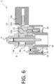
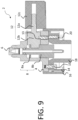
- the connection device 2 comprises a valve pusher 8 (or flap pusher visible in the Figures 3 , 6 , 9 10 And 15 ).
- the valve pusher 8 is configured to be mounted on the body 4 and alternately dismounted from the body 4.
- the valve pusher 8 is configured to be moved between a retracted position or a high position (visible to Figures 3 , 6 And 15 ) in which the valve pusher 8 is moved back to allow the closing of a valve 10a of a gas cartridge 10 (visible in the Figure 15 ) and an advanced position or low position (visible at the Figure 9 ) in which the valve pusher 8 is advanced to allow the opening of the valve 10a of the gas cartridge 10.
- the valve pusher 8 is configured to slide inside the body 4.
- the valve pusher 8 is tubular in shape.
- Gas cartridge 10 (visible at the Figure 15 ) comprises a valve.
- the valve comprises the flap 10a, a seat 10b (or seal) and an elastic return member (not shown) returning the flap 10a towards the seat 10b.
- the flap 10a comprises a bottom wall 10c.
- the flap 10a comprises a crosspiece 10d arranged on the bottom wall 10c to allow a distance to be maintained between the valve pusher 8 and the bottom wall 10c of the flap 10a when the valve pusher 8 is in the advanced position (visible in Figure 9 ).
- the 10 gas cartridge also has a 10f collar.
- valve pusher 8 When the valve pusher 8 is in the retracted position (visible at Figures 3 6 And 15 ), the elastic return member pushes the valve 10a in the direction of the seat 10b.
- the valve 10a is in contact with the seat 10b and the gas contained by the gas cartridge 10 cannot flow between the valve 10a and the seat 10b and consequently cannot flow from the outside of the valve 10a to the inside of the valve 10a.
- the connection device 2 comprises a control member 12.
- the control member 12 is configured to be mounted on the body 4 and alternately dismounted from the body 4.
- the control member 12 is configured to be moved between a closed position (visible in Figures 1 to 6 And 12 to 15 ) and an opening position (visible at Figures 7 to 9 ).
- a closed position visible in Figures 1 to 6 And 12 to 15
- an opening position visible at Figures 7 to 9 .
- the control member 12 moves the valve pusher 8 to the retracted position (visible in Figures 3 , 6 And 15 ).
- the control member 12 moves the valve pusher 8 to the advanced position (visible in the Figure 9 ).
- valve pusher 8 and the control member 12 are configured so that when the control member 12 is moved between the first intermediate position (visible in the Figure 11 ) and a second intermediate position (not shown) with a fixed pitch the valve pusher 8 is moved between the retracted position (visible at Figures 3 , 6 And 15 ) and a third intermediate position (not shown) with a variable pitch.
- valve pusher 8 and the control member 12 are configured so that when the control member 12 is moved between the second intermediate position (not shown) and the opening position (visible in Figures 7 to 9 ) with a fixed pitch, the valve pusher 8 is moved between the third intermediate position (not shown) and the advanced position (visible in the Figure 9 ) with a fixed or variable pitch.
- valve pusher 8 When the control member is moved between the first intermediate position (visible at Figure 11 ) and the second intermediate position (not shown) the valve pusher 8 is fluidically connected to the gas cartridge 10.
- the opening The gas flow rate flowing through the valve 10a of the gas cartridge 10 increases (for example non-linearly or sinusoidally).
- valve pusher 8 When the control member 12 is moved between the second intermediate position (not shown) and the open position (visible in Figures 7 to 9 ) the valve pusher 8 is always fluidically connected to the gas cartridge.
- the opening of the valve 10a of the gas cartridge 10 increases (for example linearly or sinusoidally) until it reaches a maximum opening.
- the gas flow rate flowing through the valve 10a of the gas cartridge 10 increases (for example linearly or sinusoidally) until it reaches a maximum flow rate.
- the locking member 14 comprises a ring comprising tabs.
- the tabs extend longitudinally (i.e., extending along an axis parallel to the axis of the valve pusher 8).
- the tabs are elastically deformable radially (i.e., are elastically deformable or movable along a plane perpendicular to the axis of the valve pusher 8).
- the connection device 2 comprises a control member 16 configured to be moved between an unlocking position (visible in Figures 1 to 3 ) and a locking position (visible at Figures 4 to 9 , 14 and 15 ).
- an unlocking position visible in Figures 1 to 3
- a locking position visible at Figures 4 to 9 , 14 and 15 .
- the control member 16 moves the locking member 14 into the locked position (visible in Figures 6 , 9 And 15 ).
- the control member 16 moves the locking member 14 into the unlocked position (visible in the Figure 3 ).
- connection device 2 The user fluidly connects the connection device 2 to the gas cartridge 10.
- the user moves the control member 12 from the closed position to the open position (visible in Figures 7 to 9 ).
- the user mechanically disconnects the connection device 2 from the gas cartridge 10.
- the centering member 18 is no longer received in the collar 10f of the gas cartridge 10.
- the plurality of magnets 20 no longer retains the connection device 2 from the gas cartridge 10.
Landscapes
- Engineering & Computer Science (AREA)
- Mechanical Engineering (AREA)
- General Engineering & Computer Science (AREA)
- Feeding And Controlling Fuel (AREA)
Claims (15)
- Verbindungsvorrichtung (2; 102; 202) für ein Gasgerät, umfassend:einen Ventildrücker (8), der dazu eingerichtet ist, dass er zwischen einer zurückgezogenen Position, in der der Ventildrücker (8) zurückgezogen ist, um das Schließen eines Klappventils (10a) eines Ventils einer Gaskartusche (10) zu ermöglichen, und einer vorgeschobenen Position, in der der Ventildrücker (8) vorgeschoben ist, um das Klappventil (10a) des Ventils der Gaskartusche (10) zurückzudrücken und das Öffnen des Klappventils (10a) zu ermöglichen, bewegt zu werden; undein erstes Betätigungselement (12), das dazu eingerichtet ist, dass es zwischen einer Schließposition, in der das erste Betätigungselement (12) den Ventildrücker (8) in die zurückgezogene Position bewegt, und einer Öffnungsposition, in der das erste Betätigungselement (12) den Ventildrücker in die vorgeschobene Position bewegt, bewegt zu werden.
- Verbindungsvorrichtung (2; 102; 202) für ein Gasgerät nach Anspruch 1, wobei der Ventildrücker (8) und das erste Betätigungselement (12) dazu eingerichtet sind, dass der Ventildrücker (8) in der zurückgezogenen Position bleibt, wenn das erste Betätigungselement (12) zwischen der Schließposition und einer ersten Zwischenposition bewegt wird.
- Verbindungsvorrichtung (2; 102; 202) für ein Gasgerät nach Anspruch 2, wobei der Ventildrücker (8) und das erste Betätigungselement (12) dazu eingerichtet sind, dass:wenn das erste Betätigungselement (12) mit einem festen Schritt zwischen der ersten Zwischenposition und einer zweiten Zwischenposition bewegt wird, der Ventildrücker (8) mit einem variablen Schritt zwischen der zurückgezogenen Position und einer dritten Zwischenposition bewegt wird; und/oderwenn das erste Betätigungselement (12) mit einem festen Schritt zwischen der zweiten Zwischenposition und der Öffnungsposition bewegt wird, der Ventildrücker (8) mit einem festen oder variablen Schritt zwischen der dritten Zwischenposition und der vorgeschobenen Position bewegt wird.
- Verbindungsvorrichtung (2; 102; 202) für ein Gasgerät nach Anspruch 3,
wobei das erste Betätigungselement (12) eine Nockenwelle (12a), eine an einem ersten Ende der Nockenwelle (12a) montierte Nocke (12b), die so angeordnet ist, dass sie auf den Ventildrücker (8) drückt, und einen Einstellknopf (12c), der an einem zweiten Ende der Nockenwelle (12a) montiert ist, umfasst. - Verbindungsvorrichtung (2; 102; 202) für ein Gasgerät nach Anspruch 3, wobei:das erste Betätigungselement (12) mindestens zwischen 0 und 180 Grad gedreht wird;die erste Zwischenposition zwischen 20 und 100 Grad liegt; und/oderdie zweite Zwischenposition zwischen 105 und 180 Grad liegt.
- Verbindungsvorrichtung (2; 102; 202) für ein Gasgerät nach einem der Ansprüche 1 bis 5, umfassend:ein Verriegelungselement (14), das dazu eingerichtet ist, dass es zwischen einer Verriegelungsposition, in der das Verriegelungselement (14) die Verbindungsvorrichtung (2; 102; 202) mit der Gaskartusche (10) verriegelt, und einer Entriegelungsposition, in der das Verriegelungselement (14) die Verbindungsvorrichtung (2; 102; 202) von der Gaskartusche (10) entriegelt, bewegt werden kann; undein zweites Betätigungselement (16), das dazu eingerichtet ist, dass es zwischen einer Verriegelungsposition, in der das zweite Betätigungselement (16) das Verriegelungselement (14) in die Verriegelungsposition bewegt, und einer Entriegelungsposition, in der das zweite Betätigungselement (16) das Verriegelungselement in die Entriegelungsposition bewegt, bewegt werden kann.
- Verbindungsvorrichtung (2; 102; 202) für ein Gasgerät nach Anspruch 6, wobei das erste Betätigungselement (12) und das zweite Betätigungselement (16) dazu eingerichtet sind, dass:wenn sich das zweite Betätigungselement (16) in der Entriegelungsposition befindet,das zweite Betätigungselement (16) die Bewegung des ersten Betätigungselements (12) zwischen der Schließposition und der Öffnungsposition verhindert; undwenn sich das zweite Betätigungselement (16) in der Verriegelungsposition befindet,das zweite Betätigungselement (16) die Bewegung des ersten Betätigungselements (12) zwischen der Schließposition und der Öffnungsposition erlaubt.
- Verbindungsvorrichtung (2; 102; 202) für ein Gasgerät nach Anspruch 6 oder 7, wobei das erste Betätigungselement (12) und das zweite Betätigungselement (16) dazu eingerichtet sind, dass:wenn sich das zweite Betätigungselement (16) in der Entriegelungsposition befindet,das zweite Betätigungselement fluchtet mit dem ersten Betätigungselement (12); undwenn sich das zweite Betätigungselement (16) in der Verriegelungsposition befindet,das zweite Betätigungselement (16) nicht mit dem ersten Betätigungselement (12) fluchtet.
- Verbindungsvorrichtung (2; 102; 202) für ein Gasgerät nach einem der Ansprüche 6 bis 8, wobei das erste Betätigungselement (12) und das zweite Betätigungselement (16) dazu eingerichtet sind, dass:wenn sich das zweite Betätigungselement (16) in der Entriegelungsposition befindet,eine Abflachung des ersten Betätigungselements (12) einer Abflachung des zweiten Betätigungselements (16) gegenüberliegt; undwenn sich das zweite Betätigungselement (16) in der Verriegelungsposition befindet,eine Abflachung des ersten Betätigungselements (12) einer Abflachung des zweiten Betätigungselements (16) nicht gegenüberliegt.
- Verbindungsvorrichtung (2; 102; 202) für ein Gasgerät nach einem der Ansprüche 6 bis 9, wobei das Verriegelungselement (14) einen Ring mit sich längs erstreckenden Laschen umfasst; und das zweite Betätigungselement (16) einen Ring mit radial nach innen gerichteten Vorsprüngen umfasst;
wobei das zweite Betätigungselement (16) drehbar auf dem Verriegelungselement (14) montiert ist, sodass:wenn sich das zweite Betätigungselement (16) in der Verriegelungsposition befindet, die Vorsprünge gegen die Laschen drücken und die Laschen radial nach innen bewegt werden, um einen Kragen der Gaskartusche zu verriegeln; undwenn sich das zweite Betätigungselement (16) in der Entriegelungsposition befindet, die Vorsprünge die Laschen freigeben und die Laschen nicht radial nach innen bewegt werden, um einen Kragen der Gaskartusche zu verriegeln. - Verbindungsvorrichtung (2; 102; 202) für ein Gasgerät nach einem der Ansprüche 6 bis 10, wobei das erste Betätigungselement (12) und das zweite Betätigungselement (16) dazu eingerichtet sind, dass:wenn sich das erste Betätigungselement (12) in der Öffnungsposition befindet, das erste Betätigungselement (12) die Bewegung des zweiten Betätigungselements (16) zwischen der Verriegelungs- und der Entriegelungsposition verhindert; undwenn sich das erste Betätigungselement (12) in der Schließposition befindet, das erste Betätigungselement (12) die Bewegung des zweiten Betätigungselements (16) zwischen der Entriegelungs- und der Verriegelungsposition erlaubt.
- Verbindungsvorrichtung (2; 102; 202) für ein Gasgerät nach einem der Ansprüche 1 bis 11, umfassend ein Zentrierelement (18), das so angeordnet ist, dass es die Verbindungsvorrichtung (2; 102; 202) für ein Gasgerät und die Gaskartusche (10) zentriert.
- Verbindungsvorrichtung (2; 102; 202) für ein Gasgerät nach Anspruch 12, wobei das Zentrierelement einen Ring umfasst, der so angeordnet ist, dass er in einem Kragen der Gaskartusche aufgenommen wird.
- Verbindungsvorrichtung für ein Gasgerät nach Anspruch 8 oder 9, umfassend einen Magneten (20), der am Zentrierelement (18) montiert ist.
- Anordnung umfassend:ein Gasgerät; undeine Verbindungsvorrichtung (2; 102; 202) für ein Gasgerät nach einem der Ansprüche 1 bis 14.
Applications Claiming Priority (1)
| Application Number | Priority Date | Filing Date | Title |
|---|---|---|---|
| FR2104142A FR3122235B1 (fr) | 2021-04-21 | 2021-04-21 | Dispositif de connexion d’appareil à gaz |
Publications (3)
| Publication Number | Publication Date |
|---|---|
| EP4080106A1 EP4080106A1 (de) | 2022-10-26 |
| EP4080106B1 true EP4080106B1 (de) | 2025-07-02 |
| EP4080106C0 EP4080106C0 (de) | 2025-07-02 |
Family
ID=76283972
Family Applications (1)
| Application Number | Title | Priority Date | Filing Date |
|---|---|---|---|
| EP22168742.9A Active EP4080106B1 (de) | 2021-04-21 | 2022-04-19 | Gasgerät und verbindungsvorrichtung für gasgerät |
Country Status (4)
| Country | Link |
|---|---|
| EP (1) | EP4080106B1 (de) |
| KR (1) | KR20220145294A (de) |
| CN (1) | CN218954610U (de) |
| FR (1) | FR3122235B1 (de) |
Family Cites Families (4)
| Publication number | Priority date | Publication date | Assignee | Title |
|---|---|---|---|---|
| JP2691355B2 (ja) * | 1988-10-21 | 1997-12-17 | 株式会社ネリキ | 止め弁 |
| LU87671A1 (fr) * | 1990-01-31 | 1990-05-15 | Ceodeux Sa | Robinet pour gaz comprime ou liquifie |
| FR2876776B1 (fr) | 2004-10-19 | 2007-01-19 | Applic Des Gaz Soc Par Actions | Dispositif de connexion d'appareil a gaz et cartouche de gaz |
| LU91901B1 (fr) * | 2011-11-15 | 2013-05-16 | Luxembourg Patent Co | Robinet pour bouteille de gaz équipé d'un volant commandant un clapet de pression résiduelle et un clapet de fermeture |
-
2021
- 2021-04-21 FR FR2104142A patent/FR3122235B1/fr active Active
-
2022
- 2022-04-19 EP EP22168742.9A patent/EP4080106B1/de active Active
- 2022-04-21 CN CN202220941238.4U patent/CN218954610U/zh active Active
- 2022-04-21 KR KR1020220049632A patent/KR20220145294A/ko active Pending
Also Published As
| Publication number | Publication date |
|---|---|
| CN218954610U (zh) | 2023-05-02 |
| EP4080106A1 (de) | 2022-10-26 |
| FR3122235B1 (fr) | 2023-09-15 |
| FR3122235A1 (fr) | 2022-10-28 |
| KR20220145294A (ko) | 2022-10-28 |
| EP4080106C0 (de) | 2025-07-02 |
Similar Documents
| Publication | Publication Date | Title |
|---|---|---|
| FR2510714A1 (fr) | Accouplement coaxial pour tubes | |
| FR2693250A1 (fr) | Raccord de liaison pour conduites hydrauliques. | |
| FR3046211A1 (fr) | Element male ou femelle de raccord rapide et raccord rapide comprenant un tel element | |
| FR2900182A1 (fr) | Serrure multifonctionnelle pour ordinateur | |
| EP1405003B1 (de) | Anordnung zum verbinden und trennen zweier rohrabschnitte eines fluidübertragungssystems | |
| EP2781817B1 (de) | Anschlussvorrichtung und Anschluss, der eine solche Vorrichtung umfasst | |
| WO2009125105A4 (fr) | Raccord de remplissage et/ou soutirage de fluide et ensemble comprenant un raccord et un robinet | |
| FR2782365A1 (fr) | Dispositif d'accouplement d'un appareil sur une cartouche de fluide sous pression | |
| EP4080106B1 (de) | Gasgerät und verbindungsvorrichtung für gasgerät | |
| EP4080107B1 (de) | Gasgerät und verbindungsvorrichtung eines gasgeräts | |
| EP0097089A1 (de) | Selbstverriegelbare Kupplungsvorrichtung | |
| EP3265718B1 (de) | Vorrichtung zur druckflüssigkeitsversorgung und entsprechendes flüssigkeitstransferelement | |
| EP1930661A2 (de) | Zusammenklappbarer Campingkocher | |
| EP3693654B1 (de) | Liefervorrichtung für ein unter druck stehendes fluid, und speichereinheit für unter druck stehendes fluid, die eine solche vorrichtung umfasst | |
| EP4080108B1 (de) | Gaskartusche und anordnung mit einer vorrichtung zur verbindung eines gasgeräts mit einer gaskartusche | |
| FR2547012A2 (fr) | Robinet lubrifie a obturateur tournant fendu | |
| FR2800401A1 (fr) | Dispositif a raccord amovible et a clapet commande pour reseau d'adduction d'eau et ensemble de comptage le mettant en oeuvre | |
| EP0847511B1 (de) | Schnellkupplung für druckleitungen | |
| US9844298B1 (en) | Push to sear valve for a gas grill | |
| EP1196725A1 (de) | Zuführvorrichtung für eine schneekanone | |
| CA2696718C (fr) | Dispositif de verrouillage | |
| EP3845807B1 (de) | Verbesserter gaszufuhrhahn für brenner eines gas-kochgeräts | |
| EP2204600B1 (de) | Gasanschluss für die Verbindung zwischen einem Festnetz zur Versorgung von gasförmigem Fluid und einem Gerät, das mit dem gasförmigen Fluid versorgt wird | |
| EP0711522B1 (de) | Verriegelungs-/Entriegelungsventil eines Decksel auf einem Gefäss | |
| FR3057049B1 (fr) | Raccord hydraulique auto-obturant. |
Legal Events
| Date | Code | Title | Description |
|---|---|---|---|
| PUAI | Public reference made under article 153(3) epc to a published international application that has entered the european phase |
Free format text: ORIGINAL CODE: 0009012 |
|
| STAA | Information on the status of an ep patent application or granted ep patent |
Free format text: STATUS: THE APPLICATION HAS BEEN PUBLISHED |
|
| AK | Designated contracting states |
Kind code of ref document: A1 Designated state(s): AL AT BE BG CH CY CZ DE DK EE ES FI FR GB GR HR HU IE IS IT LI LT LU LV MC MK MT NL NO PL PT RO RS SE SI SK SM TR |
|
| STAA | Information on the status of an ep patent application or granted ep patent |
Free format text: STATUS: REQUEST FOR EXAMINATION WAS MADE |
|
| 17P | Request for examination filed |
Effective date: 20230313 |
|
| RBV | Designated contracting states (corrected) |
Designated state(s): AL AT BE BG CH CY CZ DE DK EE ES FI FR GB GR HR HU IE IS IT LI LT LU LV MC MK MT NL NO PL PT RO RS SE SI SK SM TR |
|
| STAA | Information on the status of an ep patent application or granted ep patent |
Free format text: STATUS: EXAMINATION IS IN PROGRESS |
|
| 17Q | First examination report despatched |
Effective date: 20230707 |
|
| GRAP | Despatch of communication of intention to grant a patent |
Free format text: ORIGINAL CODE: EPIDOSNIGR1 |
|
| STAA | Information on the status of an ep patent application or granted ep patent |
Free format text: STATUS: GRANT OF PATENT IS INTENDED |
|
| INTG | Intention to grant announced |
Effective date: 20250127 |
|
| GRAS | Grant fee paid |
Free format text: ORIGINAL CODE: EPIDOSNIGR3 |
|
| GRAA | (expected) grant |
Free format text: ORIGINAL CODE: 0009210 |
|
| STAA | Information on the status of an ep patent application or granted ep patent |
Free format text: STATUS: THE PATENT HAS BEEN GRANTED |
|
| AK | Designated contracting states |
Kind code of ref document: B1 Designated state(s): AL AT BE BG CH CY CZ DE DK EE ES FI FR GB GR HR HU IE IS IT LI LT LU LV MC MK MT NL NO PL PT RO RS SE SI SK SM TR |
|
| REG | Reference to a national code |
Ref country code: GB Ref legal event code: FG4D Free format text: NOT ENGLISH |
|
| REG | Reference to a national code |
Ref country code: CH Ref legal event code: EP |
|
| REG | Reference to a national code |
Ref country code: DE Ref legal event code: R096 Ref document number: 602022016684 Country of ref document: DE |
|
| REG | Reference to a national code |
Ref country code: IE Ref legal event code: FG4D Free format text: LANGUAGE OF EP DOCUMENT: FRENCH |
|
| U01 | Request for unitary effect filed |
Effective date: 20250709 |
|
| U07 | Unitary effect registered |
Designated state(s): AT BE BG DE DK EE FI FR IT LT LU LV MT NL PT RO SE SI Effective date: 20250812 |
|
| REG | Reference to a national code |
Ref country code: GR Ref legal event code: EP Ref document number: 20250401935 Country of ref document: GR Effective date: 20251112 |
|
| PG25 | Lapsed in a contracting state [announced via postgrant information from national office to epo] |
Ref country code: IS Free format text: LAPSE BECAUSE OF FAILURE TO SUBMIT A TRANSLATION OF THE DESCRIPTION OR TO PAY THE FEE WITHIN THE PRESCRIBED TIME-LIMIT Effective date: 20251102 |
|
| PG25 | Lapsed in a contracting state [announced via postgrant information from national office to epo] |
Ref country code: NO Free format text: LAPSE BECAUSE OF FAILURE TO SUBMIT A TRANSLATION OF THE DESCRIPTION OR TO PAY THE FEE WITHIN THE PRESCRIBED TIME-LIMIT Effective date: 20251002 |
|
| PG25 | Lapsed in a contracting state [announced via postgrant information from national office to epo] |
Ref country code: HR Free format text: LAPSE BECAUSE OF FAILURE TO SUBMIT A TRANSLATION OF THE DESCRIPTION OR TO PAY THE FEE WITHIN THE PRESCRIBED TIME-LIMIT Effective date: 20250702 |
|
| PG25 | Lapsed in a contracting state [announced via postgrant information from national office to epo] |
Ref country code: CZ Free format text: LAPSE BECAUSE OF FAILURE TO SUBMIT A TRANSLATION OF THE DESCRIPTION OR TO PAY THE FEE WITHIN THE PRESCRIBED TIME-LIMIT Effective date: 20250702 |
|
| PG25 | Lapsed in a contracting state [announced via postgrant information from national office to epo] |
Ref country code: PL Free format text: LAPSE BECAUSE OF FAILURE TO SUBMIT A TRANSLATION OF THE DESCRIPTION OR TO PAY THE FEE WITHIN THE PRESCRIBED TIME-LIMIT Effective date: 20250702 |
|
| PG25 | Lapsed in a contracting state [announced via postgrant information from national office to epo] |
Ref country code: RS Free format text: LAPSE BECAUSE OF FAILURE TO SUBMIT A TRANSLATION OF THE DESCRIPTION OR TO PAY THE FEE WITHIN THE PRESCRIBED TIME-LIMIT Effective date: 20251002 |
|
| PG25 | Lapsed in a contracting state [announced via postgrant information from national office to epo] |
Ref country code: ES Free format text: LAPSE BECAUSE OF FAILURE TO SUBMIT A TRANSLATION OF THE DESCRIPTION OR TO PAY THE FEE WITHIN THE PRESCRIBED TIME-LIMIT Effective date: 20250702 |
|
| PG25 | Lapsed in a contracting state [announced via postgrant information from national office to epo] |
Ref country code: SM Free format text: LAPSE BECAUSE OF FAILURE TO SUBMIT A TRANSLATION OF THE DESCRIPTION OR TO PAY THE FEE WITHIN THE PRESCRIBED TIME-LIMIT Effective date: 20250702 |
|
| PG25 | Lapsed in a contracting state [announced via postgrant information from national office to epo] |
Ref country code: SK Free format text: LAPSE BECAUSE OF FAILURE TO SUBMIT A TRANSLATION OF THE DESCRIPTION OR TO PAY THE FEE WITHIN THE PRESCRIBED TIME-LIMIT Effective date: 20250702 |