EP2781817B1 - Anschlussvorrichtung und Anschluss, der eine solche Vorrichtung umfasst - Google Patents
Anschlussvorrichtung und Anschluss, der eine solche Vorrichtung umfasst Download PDFInfo
- Publication number
- EP2781817B1 EP2781817B1 EP14161106.1A EP14161106A EP2781817B1 EP 2781817 B1 EP2781817 B1 EP 2781817B1 EP 14161106 A EP14161106 A EP 14161106A EP 2781817 B1 EP2781817 B1 EP 2781817B1
- Authority
- EP
- European Patent Office
- Prior art keywords
- axis
- diameter
- connecting device
- centered
- articulation
- Prior art date
- Legal status (The legal status is an assumption and is not a legal conclusion. Google has not performed a legal analysis and makes no representation as to the accuracy of the status listed.)
- Active
Links
- 230000007246 mechanism Effects 0.000 claims description 36
- 230000000295 complement effect Effects 0.000 claims description 31
- 238000006073 displacement reaction Methods 0.000 claims description 24
- 239000012530 fluid Substances 0.000 claims description 23
- 238000013519 translation Methods 0.000 claims description 6
- 230000008878 coupling Effects 0.000 description 49
- 238000010168 coupling process Methods 0.000 description 49
- 238000005859 coupling reaction Methods 0.000 description 49
- 238000007789 sealing Methods 0.000 description 7
- 239000002184 metal Substances 0.000 description 6
- 229910052751 metal Inorganic materials 0.000 description 6
- 239000000470 constituent Substances 0.000 description 4
- 230000033001 locomotion Effects 0.000 description 4
- 230000036961 partial effect Effects 0.000 description 4
- 238000010079 rubber tapping Methods 0.000 description 4
- 238000012423 maintenance Methods 0.000 description 3
- 238000010276 construction Methods 0.000 description 2
- 230000000670 limiting effect Effects 0.000 description 2
- 239000000463 material Substances 0.000 description 2
- 230000002829 reductive effect Effects 0.000 description 2
- 229910001220 stainless steel Inorganic materials 0.000 description 2
- 240000008042 Zea mays Species 0.000 description 1
- 238000009826 distribution Methods 0.000 description 1
- 230000001976 improved effect Effects 0.000 description 1
- 230000001965 increasing effect Effects 0.000 description 1
- 238000003780 insertion Methods 0.000 description 1
- 230000037431 insertion Effects 0.000 description 1
- 230000002427 irreversible effect Effects 0.000 description 1
- 210000003127 knee Anatomy 0.000 description 1
- 210000000629 knee joint Anatomy 0.000 description 1
- 230000009021 linear effect Effects 0.000 description 1
- 239000007788 liquid Substances 0.000 description 1
- 230000007935 neutral effect Effects 0.000 description 1
- 230000000149 penetrating effect Effects 0.000 description 1
- 230000002093 peripheral effect Effects 0.000 description 1
- 239000002861 polymer material Substances 0.000 description 1
- 230000004044 response Effects 0.000 description 1
- 210000003462 vein Anatomy 0.000 description 1
Images


Classifications
-
- F—MECHANICAL ENGINEERING; LIGHTING; HEATING; WEAPONS; BLASTING
- F16—ENGINEERING ELEMENTS AND UNITS; GENERAL MEASURES FOR PRODUCING AND MAINTAINING EFFECTIVE FUNCTIONING OF MACHINES OR INSTALLATIONS; THERMAL INSULATION IN GENERAL
- F16L—PIPES; JOINTS OR FITTINGS FOR PIPES; SUPPORTS FOR PIPES, CABLES OR PROTECTIVE TUBING; MEANS FOR THERMAL INSULATION IN GENERAL
- F16L37/00—Couplings of the quick-acting type
- F16L37/08—Couplings of the quick-acting type in which the connection between abutting or axially overlapping ends is maintained by locking members
- F16L37/12—Couplings of the quick-acting type in which the connection between abutting or axially overlapping ends is maintained by locking members using hooks, pawls or other movable or insertable locking members
- F16L37/18—Joints tightened by eccentrics or rotatable cams
-
- F—MECHANICAL ENGINEERING; LIGHTING; HEATING; WEAPONS; BLASTING
- F16—ENGINEERING ELEMENTS AND UNITS; GENERAL MEASURES FOR PRODUCING AND MAINTAINING EFFECTIVE FUNCTIONING OF MACHINES OR INSTALLATIONS; THERMAL INSULATION IN GENERAL
- F16L—PIPES; JOINTS OR FITTINGS FOR PIPES; SUPPORTS FOR PIPES, CABLES OR PROTECTIVE TUBING; MEANS FOR THERMAL INSULATION IN GENERAL
- F16L19/00—Joints in which sealing surfaces are pressed together by means of a member, e.g. a swivel nut, screwed on or into one of the joint parts
- F16L19/02—Pipe ends provided with collars or flanges, integral with the pipe or not, pressed together by a screwed member
- F16L19/0212—Pipe ends provided with collars or flanges, integral with the pipe or not, pressed together by a screwed member using specially adapted sealing means
- F16L19/0225—Pipe ends provided with collars or flanges, integral with the pipe or not, pressed together by a screwed member using specially adapted sealing means without sealing rings
Definitions
- the present invention relates to a coupling device.
- the invention also relates to a coupling comprising such a device.
- the field of the invention is that of connectors adapted to the passage of fluids under high pressures and high or very low temperatures, which require maximum safety and require sealing by metal parts.
- a seal is made by metal-to-metal contact, without using a seal made of a polymer material.
- the invention is well adapted to particular applications in the field of cryogenics.
- GB-A-163,053 describes a connecting device between two tubes.
- a first tube is screwed into a main coupling element provided with a first frustoconical surface.
- the second tube is screwed into a coupling ring provided with a second frustoconical surface and slidably mounted in the main element.
- the device also includes a cam lever mounted on the coupling member after insertion of the second tube into the ring. Actuation of the cam lever allows the two frustoconical surfaces to be brought together and then the application of a contact pressure, thus achieving a truncated frustum of cone on a truncated cone within the device. In practice, this sealing requires exerting high forces of the cam lever on the contact surfaces.
- the contacts between the cam carried by the lever and the ring to move are linear contacts, which poses a problem of compactness and / or resistance when the materials, in particular for reasons of compatibility with certain fluids, do not exhibit a hardness. sufficient to resist ma
- US-A-5,350,200 describes another connection device between two tubes, provided with complementary frustoconical surfaces.
- the coupling device comprises two annular rings, each having a cavity for receiving one of the tubes.
- the annular rings further comprise complementary threads and threads. The screwing of the annular rings enables the two surfaces to be brought together and then the application of a contact pressure, thus achieving a truncated cone seal on a truncated sphere within the device, according to the preamble of claim 1.
- very low temperature applications can use austenitic stainless steels, for example of the 316L type, which have a high tenacity under cryogenic temperatures but a low hardness.
- the object of the present invention is to provide an improved coupling device, particularly for high temperature or very low temperature applications.
- the coupling device according to the invention has many advantages, which will emerge from the description below.
- the coupling device allows to obtain a reliable and ergonomic connection between two coupling elements, using displacement means providing reduced contact pressures and compactness.
- the invention also relates to a fitting adapted to transmit fluids under pressure.
- This connection is characterized in that it comprises a connecting device as mentioned above, as well as a complementary connecting element which is able to be coupled to the coupling device and which comprises a duct defining a bearing surface. complementary to the bearing surface of the coupling device, and in that the bearing surface of the complementary coupling element and the bearing surface of the coupling device are in conical frustoconical contact with a truncated cone or contact portion of sphere on a truncated cone to form the sealed connection between the tip duct and the duct.
- the complementary coupling element comprises a movable locking mechanism between, on the one hand, a locking position of the conduit of the complementary coupling element introduced into a body of the complementary coupling element with respect to said body of the complementary coupling element, in at least one direction parallel to a longitudinal axis of the complementary coupling element and opposite to the coupling device and, secondly, a position where the locking mechanism allows removal of the conduit of the coupling element from the body of the complementary coupling element.
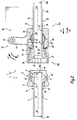
- This connection 1 comprises a connecting element 2 and a connecting device 10, which is also in accordance with the invention.
- the element 2 is shaped as a male connector end, while the device 10 is shaped as a female connector end, adapted to receive the element 2.
- the device 10 is intended to be connected to a first pipe, while the element 2 is intended to be coupled to the coupling device 10 and to be connected to a second pipe, these pipes not being represented on the Figures 1 to 8 for the sake of simplification.
- the coupling 1 is shown in a configuration uncoupled to figures 1 , 2 and 7 , being mated to the figure 3 and in a configuration coupled with figures 4 , 5 and 8 .
- the element 2 and the device 10 are the two constituent elements of the coupling 1, adapted to transmit gaseous and / or liquid fluids at high pressures and at high temperatures (up to 450 ° C.) or at very low temperatures (for example up to 30 ° C.). at -250 ° C) when fitting 1 is in coupled configuration.
- the device 10 is connected at the first pipe, while the element 2 is coupled to the connecting device 10 and connected to the second pipe, so that a fluid can pass through the connection 1 of a pipe to the other.
- the constituent elements 2 and 10 of the coupling 1 are made of metal, in order to withstand high pressures and high or very low temperatures.
- very low or very high temperature applications may use austenitic stainless steels, for example 316L type.
- the connecting element 2 comprises a body 3 and a duct 4 generally centered on a longitudinal axis X2.
- the body 3 defines a front side of the element 2, whereas the conduit 4 extends towards the rear of the element 2.
- the body 3 has an inner cavity 3a, an annular surface 3b and an inner bore 3c.
- the annular surface 3b extends radially to the axis X2 between the cavity 3a and the bore 3c, which are centered on the axis X2.
- the surface 3b is oriented on the front side of the element 2.
- the body 3 also comprises an external peripheral thread 5, forming a complementary gripping profile of a gripping profile 25 formed on the device 10, as detailed below.
- the duct 4 comprises a head 6 disposed in the cavity 3a of the body 3, and a tube 7 which extends rearwardly from the head 6 through the bore 3c.
- the conduit 4 is traversed by an internal channel 8 which extends along the axis X2 between a front mouth 8a and a rear mouth 8b.
- the front mouth 8a of the channel 8 opens at the head 6 and is intended to be coupled to the device 10.
- the rear mouth 8b of the channel 8 opens out of the tube 7 opposite the head 6 and is connected to the pipe not shown.
- the head 6 has an outer cylindrical surface 6a centered on the axis X2, and a rear annular surface 6b which extends radially to the axis X2.
- the surface 6a is received in the cavity 3a, while the surface 6b is provided to abut against the surface 3a of the body 3.
- a groove 7a receiving a circlip 7b of generally annular shape is formed in the tube 7, leading to level of its external surface. Circlip 7b does not form a complete ring to facilitate its introduction into the groove 7a.
- the head 6 also comprises a surface 9, in a portion of sphere centered on the axis X 2, oriented towards the front and the outside of the element 2.
- the spherical surface 9 is tightens away from the tube 7.
- the spherical surface 9 constitutes a bearing portion for a complementary frustoconical surface 39 belonging to the device 10, as shown in FIGS. figures 3 and 5 .
- Such spherical / frustoconical sealing by metal-to-metal contact is well suited to fluids with high pressures and high temperatures or very low temperatures.
- the sealing sphere portion on truncated cone does not require a seal, resulting in lighter maintenance.
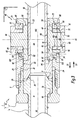
- the connecting device 10 extends generally along a longitudinal central axis X10, which is aligned with the axis X2 of the coupling element 2 when the coupling 1 is in coupled configuration.
- the connecting device 10 comprises a threaded tip body 20, a tip duct 30 movable relative to the body 20, and a mechanism 40 for moving the conduit 30 relative to the body 20 in the longitudinal direction defined by the X10 axis.
- the conduit 30 is traversed, along the axis X10, by a main channel 38 of fluid flow in the device 10. In the coupled configuration of the coupling 1 shown in FIG. figure 5 , the channel 8 and the channel 38 are connected in a sealed manner, thus allowing the flow of fluid in the connection 1.
- the threaded tip body 20 has a generally tubular shape.
- the body 20 extends along the axis X10 between a front end 20a of coupling to the element 2 and a rear end 20b of sliding of the conduit 30 along the axis X10.
- the body 20 includes a first bore 21 located on the end side 20a, a second bore 22 intermediate and a third bore 23 located on the end side 20b.
- the bores 21, 22, 23 are centered on the axis X10.
- the diameter of the bore 21 is greater than the diameter of the bore 22, which is greater than the diameter of the bore 23, these diameters being measured around the axis X10.
- a housing 80 opening on either side of the body 20, as detailed below.
- the bores 21, 22, 23 and the housing 80 delimit an interior cavity 24 called dry, in the sense that the cavity 24 is isolated from the channel 38 of the flow of the fluid circulating in the device 10.
- This cavity 24 passes through the body 20 from one side along the longitudinal axis X10, between the ends 20a and 20b.
- the conduit 30 can translate along the axis X10 relative to the tip body 20, being guided in the bores 22 and 23.
- the body 20 comprises a gripping profile 25, which is more precisely an internal thread, that is to say a tapping, formed around the axis X10 at the surface of the first bore 21 on the end side. 20a.
- the engagement profile 25 formed on the body 20 is complementary to the engagement profile 5 formed on the body 3 of the element 2, for the purpose of coupling the element 2 and the device 10 forming the connection 1.
- the housing 80 formed in the body 20 is provided to receive the various components of the mechanism 40.
- the housing 80 comprises a first bore 81 centered on the axis X10, a shoulder 82 which extends radially to the axis X10 between the bore 81 and the bore 22, two portions 83 of frustoconical inner surface centered on the axis X10, a second bore 84 arranged in a direction radial to the axis X10 at the bore 81 and portions 83 and opening on either side of the body 20, and two lateral rear seats 85 formed in a direction radial to the axis X10 by partially cylindrical profile bores.
- Each bore 85 opens out, on the one hand, outside the body 20 and, on the other hand, in the body 20 at the bore 84.
- the bores 85 are both centered on an axis A3 which is perpendicular to the axis X10 and which is offset from the axis of the bore 84 along the axis X10.
- the tip conduit 30 comprises a head 31 provided for connection to the conduit 4 of the element 2 and a rear tube 32 connected to the pipe not shown.
- the head 31 and the tube 32 each have a tubular shape centered on the axis X10.
- the head 31 has an outer cylindrical surface 33 centered on the axis X10, and a rear shoulder 34 of generally annular shape which extends radially to the axis X10 between the surface 33 and the tube 32.
- the tube 32 exceeds the rear side 20b of the body 20 at the bore 23.
- the conduit 30 is partially housed in the body 20, without being surrounded by the circulating fluid in the channel 38.
- the tube 32 has an outer cylindrical surface 35 centered on the axis X10, of diameter smaller than that of the surface 33 of the head 31.
- a groove 36 receiving a circlip 37 of annular shape is formed in the tube 32, opening at the surface 35.
- the circlip 37 does not form a complete ring to facilitate its introduction into the groove 36.
- the tip duct 30 is traversed by the internal channel 38 which extends along the axis X10 between a front mouth 38a and a rear mouth 38b.
- the channel 38 delimits the fluid flow channel in the connecting device 10.
- the front mouth 38a of the channel 38 opens at the head 31 and is intended to be coupled to the element 2.
- the rear mouth 38b the channel 38 opens out of the tube 32 opposite the head 31 and is connected to the pipe not shown.
- the frustoconical surface 39 is formed at the front mouth 38a of the channel 38, inside and at the front of the head 31. frustoconical surface 39 is flared in the direction D1 opposite the tube 32, thus forming a complementary bearing portion of the surface 9 of the element 2.
- the mechanism 40 for moving the conduit 30 in the body 20 comprises a pivot member 50, an eccentric lever 60, two rings 70, a housing 80 formed in the body 20, a washer 90 and a spring 100.
- the pivot member 50 is disposed in the body 20 and surrounds the conduit 30. More specifically, the pivot member 50 is housed partly in the housing 80 and opens on either side of the housing 80 at the bores 85
- the pivot member 50 comprises a central portion 51 flanked by two cylindrical side portions 52.
- the central portion 51 has an outer surface 53 forming a cylindrical portion and a flat surface before 54, perpendicular to the axis X10, which are traversed by a bore 55.
- the tube 32 of the duct 30 passes through this bore 55 along a reduced clearance. of the X10 axis.
- Each side portion 52 has a cylindrical outer surface 56 coaxial with the surface 53.
- the side portions 52 are mounted in the lever 60, as detailed hereinafter.
- the lateral portions 52 and their cylindrical surfaces 56 are centered on an axis A1.
- the plane front surface 54 is in contact with the washer 90, itself bearing against the surface 34 of the duct 30 in a recessed configuration of the duct 30.
- the plane front surface 54 is able to push the duct 30 in the forward direction D1 .
- the contacts between the elements 50, 90 and 30 are surface contacts, referred to as surface contacts.
- the eccentric lever 60 is rotatable about the axis A1 by actuation of the operator, on the one hand, in a locking direction L1 towards a locked position and, on the other hand, in a direction of unlatching L2 opposite L1 direction towards an unlocked position.
- the lever 60 comprises two lever arms 61 connected by a handle 62.
- the handle 62 is formed by a cylindrical shaft which extends between the arms 61 in a direction transverse to the central axis X10. For the sake of simplification, on figures 1 and 4 one of the arms 61 is not shown while the handle 62 is shown in section.
- Each lever arm 61 has an elongated portion 63 and an eccentric cylindrical portion 64, integral with each other.
- the elongated portion 63 is located on the outer side of the device 10, while the eccentric portion 64 is located on the inside of the elongate portion 63 relative to the central axis X10.
- the elongate portion 63 is located outside the housing 80, while the eccentric portion 64 enters the bore 85 of the housing 80.
- the arm 61 is traversed, both in its elongated portion 63 and its eccentric portion 64, by a bore 65 centered on the axis A1.
- the bore 65 is provided to receive one of the lateral parts of the pivot member 50, so that the surface 56 and the bore 65 pivot relative to each other about the axis A1.
- the eccentric portion 64 has an outer cylindrical surface 66 centered on an axis A2 parallel but offset with respect to the axis A1.
- the bore 65 and the cylindrical surface 66 are eccentric.
- the cylindrical surface 66 completely surrounds the bore 65 and in particular is disposed at the same level as the bore 65 in a transverse direction parallel to the axes A1, A2 and A3, that is to say in the same region along this transverse direction. In other words, a plane perpendicular to this transverse direction intersects the bore 65 and the cylindrical surface 66.
- Each eccentric portion 64 of the lever 60 is mounted in a connecting ring 70, as detailed below.
- the elongated portion 63 has an orifice 67 formed opposite the eccentric portion 64 and the bore 65 along this elongate portion 63.
- the handle 62 is fixed at each of its ends to one of the arms 61 by a screw 68 passing through the orifice 67. The fixing by screw 68 keeps the eccentric lever 60 and the connecting rings 70 mounted around the pivot member 50.
- Each lever arm 61 also comprises a pin 69 of cylindrical shape, positioned on the inside of the lever 60, next to the eccentric portion 64. Each pin 69 is provided to cooperate with one of the connecting rings 70, as detailed below. after.
- the pawn 69 shown to figures 1 , 4 , 7 and 8 belongs to an arm 61 not shown for simplification purposes.
- the connecting rings 70 are mounted on the eccentric portions 64 of the lever 60. Each connecting ring 70 is housed with clearance in the bore 84 and in one of the bores 85 of the housing 80 formed in the body 20. Each connecting ring 70 comprises an inner bore 72, and an outer surface 73 comprising a front outer surface 74 and a rear outer surface 75 connected by two flat surfaces 76. The bore 72 and the surface 74 are centered on the axis A2. The surfaces 74 and 75 form cylinder portions, with the surface 75 having a smaller diameter than the surface 74. The bore 72 is provided to pivot about the surface 66 of the eccentric portion 64. The surface 75 is eccentric by relative to the axis A2 and is provided to slide in the bore 85 of the housing 80 about the axis A3.
- Each connecting ring 70 is rotatable, on the one hand, with respect to the eccentric portion 64, around the cylindrical surface 66 and on the axis A2 and, on the other hand, with respect to the end body 20, around the axis A3 fixed relative to the housing 80 when the sliding surface 75 is in contact with the bore 85.
- the outer surface 73 of the connecting ring 70 formed of the surfaces 74, 75 and 76, is arranged around the bore 72.
- the rear outer surface 75 is disposed at the same level as the bore 72 in a transverse direction parallel to the axes A1, A2 and A3, that is to say in the same region the along this transverse direction. In other words, a plane perpendicular to this transverse direction intersects the bore 72 and the rear surface 75.
- the rear surface 75 in its extension about the axis A3 is secant with the cylindrical surface formed by the bore 72 and alternatively not shown, completely surrounds the cylindrical surface formed by the bore 72.
- the washer 90 is disposed in the housing 80 and comprises a generally tubular main portion 91, which is traversed by a cylindrical bore 92 centered on the axis X10.
- the portion 91 extends along the axis X10 between two generally annular end surfaces 93 and 94, which extend radially to the axis X10.
- the bore 92 is traversed by the tube 32 of the duct 30.
- the surface 93 is oriented towards the rear of the device 10 and placed in abutment against the surface 54 of the pivot member 50.
- the surface 94 is oriented towards the front of the device 10 and disposed in abutment against the surface 34 of the conduit 30.
- the washer 90 also comprises a flange 95 which extends radially to the axis X10 from an outer surface of the portion 91, substantially midway between the surfaces 93 and 94.
- the flange 95 is located opposite the bore 81 of the housing 80 radially to the axis X10.
- the portion 91, the surfaces 93 and 94 and the flange 95 are truncated by two flat surfaces 96.
- the surfaces 96 are parallel to each other and to the axis X10.
- the spring 100 is disposed in the housing 80, on the washer 90.
- the spring 100 has a generally annular shape centered on the axis X10.
- the spring 100 has an inner port 101, a rear side 102 and a front side 103.
- the port 101 is provided to receive the main portion 91 of the washer.
- the spring 100 is positioned on the washer 90, on the side of the collar 95 which is closer to the surface 94 than the surface 93.
- the rear side 102 is disposed in contact with the collar 95.
- the front side 103 is disposed at contact of the surface 82 of the housing 80 formed in the tip body 20.
- the axis of rotation A1 between the pivot member 50 and the eccentric lever 60, the axis of rotation A2 between the eccentric lever 60 and the connecting rings 70 and the axis of rotation A3 between the connecting rings 70 and the body 20 are distinct, that is, non-aligned.
- the axes A1, A2 and A3 are substantially parallel to each other and parallel to a transverse direction of the device 10, that is to say perpendicular to a plane P1 including the central axis X10.
- the axes A1, A2, and A3 extend in a direction perpendicular to the plane P1 including the axis X10.
- This plane P1 constitutes a plane of symmetry of the device 10, except at the tapping 25.
- the axes A1 and A3 are located substantially in the same plane P2 perpendicular to the plane of symmetry P1.
- the plane P2 includes the central axis X10.
- the plane P2 may be parallel to the axis X10.
- Plan P1 corresponds to the plan of the figure 2
- the P2 plan corresponding to the plane of figures 3 and 5 .
- the axis A1 is movable in the plane P2 along the axis X10, while the axis A3 is fixed.
- the axis A2 is movable on both sides of the plane P2, by pivoting the eccentric lever 60 both around the movable axis A1 and around the fixed axis A3 between the unlocked configuration and the locked configuration.
- the axis A2 is situated generally between the axes A1 and A3 in the longitudinal direction defined by the axis X10.
- the distance between the axes A1 and A2 is constant and corresponds to the eccentricity of the surfaces 65 and 66.
- the distance between the axes A2 and A3 is constant and corresponds to the eccentricity of the surfaces 72 and 75.
- the distance between the axes A1 and A2 are smaller, of the order of 10 times, preferably at least 5 times, at the distance between the axis A2 and the axis A3.
- the distance between the axes A1 and A3 is lower in the unlocked configuration with respect to the locked configuration of the mechanism 40.
- the axis A2 In the unlocked configuration, the axis A2 is located on one side of the plane P2. In the locked configuration, the axis A2 is located on the other side of the plane P2 and is closer to this plane P2 than in the unlocked configuration.
- the mechanism 40 may be configured such that the axis A2 is movable only on one side of the plane P2, by pivoting the eccentric lever 60 at a time around the movable axis A1 and around the fixed axis A3 . In this case, the mechanism 40 does not exhibit irreversibility. So that the mechanism 40 can be maintained in its locked configuration when the lever 60 in the locked position, the device 10 can be equipped with locking means in the locked position of the lever 60 and / or another movable member constituting the mechanism 40 .
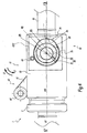
- the constituent elements of the mechanism 40 define a first diameter ⁇ 1 of articulation between the pivot member 50 and the eccentric lever 60 around the first axis A1, a second diameter ⁇ 2 of articulation between the eccentric lever 60 and the connecting rings 70 about the second axis A2, and a third diameter ⁇ 3 of articulation between the link member 70 and the rear housing 85 around the third axis A3.
- the diameters ⁇ 1, ⁇ 2 and ⁇ 3 are represented in Figures 3 to 5 and 7 .
- the diameter ⁇ 1 is equal to 5 mm
- the diameter ⁇ 2 is equal to 7.5 mm
- the diameter ⁇ 3 is equal to 8.5 mm.
- the half-sum of the diameters ⁇ 1 and ⁇ 2 is therefore 6.25 mm.
- the half-sum of the diameters ⁇ 2 and ⁇ 3 is therefore 8 mm.
- the distance between the axis A1 and the axis A2 is equal to 0.15 mm and the distance between the axis A2 and the axis A3 is equal to 1.5 mm.
- connection 1 is initially uncoupled configuration, that is to say that the connecting element 2 and the connecting device 10 are uncoupled.
- the eccentric lever 60 is in the unlocked position, with the arms 61 extending on either side of the body 20 in a direction generally perpendicular to the axis X1 and P2 plane.
- each pin 69 carried by the lever 60 is supported on one of the plane surfaces 76 of the connecting rings 70.
- This cooperation between the pin 69 and the ring connecting rod 70 limits the angular position of the lever 60 about the axis A1, in other words prevents the rotation of the lever 60 about the axis A1 in the unlocking direction L2.
- the lever 60 is returned in this position by the spring 100, which pushes in the rear direction D2 the washer 90, the pivot member 50, the eccentric lever 60 and the connecting rings 70 in rear abutment on the body 20.
- each rear surface 75 is in rear abutment along the axis X10 in the bore 85 corresponding.
- the lever 60 is still in the unlocked position.
- Each pin 69 cooperates with the plane surface 76 of one of the connecting rods 70.
- the complementary element 2 of the device 10 is screwed into the body 20, more precisely the thread 5 is screwed into the tapping 25, until it is contact surfaces 9 and 39 and push the surface 34 of the conduit 30 in abutment against the surface 94 of the washer 90, while the surface 6b of the conduit 4 is pushed in abutment against the surface 3b of the body 3 of the element 2.
- the body 3 of the element 2 enters the cavity 24 of the body 20, the head 31 of the conduit 30 enters the cavity 3a of the body 3 and the mouth 8a of the conduit 4 enters the mouth 38a of the conduit 30.
- body 3 and 20 are then integral in translation along the axis X10.
- the eccentric lever 60 is then actuated to bring the connector 1 in coupled configuration.
- the lever 60 is moved from its unlocked position to its locked position by pivoting in the locking direction L1, with the handle 62 coming closer to the front 20a of the body 20.
- the lever 60 is moved from the unlocked configuration to the locked configuration of the movement mechanism 40.
- the lever 60 pivots around the axis A1 in the direction L1 by an angle of about 50 °, this pivoting being limited by the abutment of the handle 62 on the body 20.
- the rotation of the lever 60 relative to the pivot member 50 occurs around the axis A1 by cooperation of the outer surface 56 with the bore 65, these surfaces defining the diameter ⁇ 1 d 'joint.
- the rotation of the lever 60 also causes the eccentric portion 66 to rotate relative to the connecting rod 70 about the axis A2 by cooperation of the bore 72 with the external surface 66, these surfaces defining the articulation diameter ⁇ 2.
- the ring rod 70 is then rotated relative to the tip body 20 about the axis A3 by the cooperation of the rear outer surface 75 with the bore 85, these surfaces defining the diameter ⁇ 3 articulation.
- the axis A2 then crosses the plane P2 comprising the axes A1 and A3 and the axis X10, between the axis A1 and the axis A3, thus penetrating into a zone of irreversibility of the locking, which guarantees the maintenance of the mechanism 40 in locked configuration.
- the movement of the axis A2 between the unlocked configuration and the locked configuration causes the displacement of the axis A1, and therefore of the tip duct 30 relative to the body 20, in the forward direction D1 along the axis X10.
- the distance between the axes A1 and A3 has increased by about 0.05 mm, that is to say that the bearing surface 54 of the pivot 50 on the washer 90, and therefore the bearing surface 94 of the washer 90 on the conduit 30, have moved 0.05 mm to the front side 20a of the body 20 during the rotation of the lever 60.
- This movement allows to bring the conduit 30 and the complementary element 2, so as to create pressure forces Fp of the surface 9 on the surface 39, thus forming a tight connection between the channels 8 and 38 at these complementary surfaces 9 and 39.
- the pressure forces Fp are represented schematically by arrows at the figure 5 .
- the surface 39 likewise exerts pressure forces on the surface 9, not shown for purposes of simplification.
- the coupling 1 in coupled configuration is sealed at the interface between the element 2 and the device 10, so that the fluid can flow through the connector 1.
- the lever 60 On disconnection, that is to say to pass from the coupled configuration to the uncoupled configuration of the connection 1, the lever 60 is rotated about the axis A1 in the unlocking direction L2, with the handle 62 which away from the front 20a of the body 20.
- the axis A2 is also moved in the opposite direction to its initial position, again crossing the P2 plane to leave the irreversibility zone.
- Each pin 69 limits the rotation of the lever 60 by cooperating with the flat surface 76 of the corresponding ring rod 70.
- Axis A1 moves in the rear direction D2 and the Fp pressure forces exerted by the surface 9 on the surface 39 are released, sealing within the connector 1 is no longer ensured.
- the surfaces 56, 65, 66, 72, 75 and 85 may be offset in a transverse direction parallel to the axes A1, A2, A3.
- the surfaces 66 and 72 surround the surfaces 65 and 56 while the outer surface 73 of the connecting ring 70 surrounds the surfaces 66 and 72.
- the surfaces 66 and 65 of the eccentric portion 64 do not surround but are intersecting, that is to say one of the surfaces 66 or 65 is contained partially in the other surface 66 or 65.
- the mechanism 40 has a small footprint in the longitudinal direction because, unlike a traditional knee joint where the joints are juxtaposed, the joints of the mechanism 40 along the axes A1, A2 and A3 are nested.
- the surfaces 56 or 65 and 66 are intersecting or the surface 56 or the surface 65 surrounds or is surrounded by the surface 66.
- the surfaces 75 and 72 are intersecting or the surface 75 surrounds the surface 72.
- the distance between the axes A1 and A2 are strictly less than the half-sum of the first and second articulation diameters ⁇ 1 and ⁇ 2 and the distance between the axes A2 and A3 is strictly less than the half-sum of the second and third articulation diameters ⁇ 2 and ⁇ 3
- the axes A1, A2 and A3 are all arranged inside all the cylindrical articulation surfaces 56, 65, 66, 72, 75, 85 of the mechanism 40, the articulation surfaces 66 and 72 between the eccentric lever 60 and the connecting rod surround the hinge surfaces 56 and 65 between the pivot member 50 and the eccentric lever 60, which ensures a maximum longitudinal compactness along the axis X10.
- the cylindrical contact interfaces or portions of the cylinder between the elements 50, 60, 70 and 80 in relative rotation are relatively large and can achieve a low displacement value of the axis A1 between the configuration unlocked and locked configuration.
- the planar surface contact interfaces between the parts 50, 90 and 30 in translation are relatively important. The increase of the contact interfaces between the parts of the device 10 makes it possible to reduce the contact pressures for a constant actuating force, which allows the use of less hard materials, and therefore more economical or more specifically adapted to certain applications. , especially in cryogenics.
- the construction with the axis A2 disposed on one side of the plane P2 in unlocked configuration and disposed on the other side of the plane P2 locked configuration allows the self-maintenance mechanism 40 locked configuration and locking with less effort when the neutral position (axes A1, A2, A3 contained in the plan P2) is exceeded.
- the parallelism of the plane P2 comprising the axes A1 and A3 with the longitudinal central axis X10 of the device 10 allows an optimum stroke for a given locking force.
- An eccentricity between the axis A2 and the axis A3 greater than the eccentricity between the axis A1 and the axis A2 allows the operation of the mechanism 40 by the eccentric lever 60, and also to limit the opening of the body 20 by the housing 80 by limiting the rotation of the connecting ring 70 between the unlocked configuration and the locked configuration.
- the mechanism 40 has a small footprint outside the end body 20 because the parts 50, 60, 70 are all at least partially disposed inside, that is to say on the side of the axis X10 relative to the outer surface of the tip body 20.
- the surfaces 56, 66, 75 and the bores 65, 72 and 85 are furthermore all arranged, at least partially, at the same level in a transverse direction parallel to the axes A1.
- each of the rear bores 85 is disposed behind the axes A1, A2 and A3 along the longitudinal axis X10.
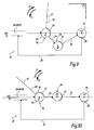
- FIGS. 9 and 10 show cinematically and schematically the constituent elements of the device 10, in an arrangement corresponding to a toggle of the state of the art, not in accordance with the invention.
- connection 1, the connecting element 2 and the connecting device 10 may be shaped differently from the Figures 1 to 8 without departing from the scope of the invention.
- the support portions 9 and 39 between the element 2 and the tip duct 30 may be shaped differently from the example of the Figures 1 to 8 .
- the portions 9 and 39 comprise at least one frustoconical surface to form a sealed direct contact.
- parts 9 and 39 both comprise a frustoconical surface.
- the parts 9 and 39 can be configured with the element 2 which is female and receives a male end pipe 30.
- the sealing contact of the parts 9 and 39 is of the truncated cone type / sphere, the female outer part is provided with a frustoconical end and the inner male part is provided with a partially spherical end.
- the seal within the connector 1 is provided by a metal seal. More specifically, the sealing contact between the element 2 and the tip duct 30 is provided by means of a metal seal, which the approximation of the parts by actuation of the eccentric lever 60 compresses between the support portions 9 and 39 of the element 2 and the tip conduit 30 to seal the connection.
- the bearing portions 9 and 39 are not necessarily frustoconical or spherical surfaces.
- the coupling member 2 comprises a socket profile, for example a tapping, while the tip body 20 comprises a plug profile, for example a thread.
- the tip conduit 30 is not shaped as a single-piece tubular body, but consists of several parts assembled together in a sealed manner.
- a valve system may be disposed inside the channel 8 of the element 2 and / or the main flow channel 38 defined by the tip conduit 30.
- the body 20 comprises a dry interior cavity 24, through, isolated from the fluid vein, that is to say in which no fluid flows directly. No fluid flows into the dry interior cavity 24 of the body 20 and the outer surface of the conduit 30 when the fluid passes through the connector 1.
- the conduit 30 is different from a valve.
- the eccentric lever 60 comprises at least one cylindrical portion which is housed in a bore of the pivot member 50. This cylindrical portion and this bore are centered on the axis A1.
- the eccentric lever 60 comprises at least one bore which receives a cylindrical portion belonging to the connecting ring 70. This bore and this cylindrical portion are centered on the axis A2 and are eccentric with respect to the axis A1 .
- the eccentric lever 60 includes means for adjusting the position of each pin 69 on the corresponding lever arm 61, in order to adjust the stroke of the lever 60 and therefore the pressure forces Fp at the surfaces 9 and 39.
- the pin 69 can be screwed at different locations along a groove in the arm 61.
- the connecting element 2 comprises a conduit 4, a body which extends along a longitudinal axis and which is provided with a radial surface having a complementary thread of the thread 25 of the tip body 20 , and a locking mechanism arranged in the threaded body of the element 2, for example ball or button, as described in the application for patent FR 11 59652 .
- the threaded body can engage with the tip body 20.
- the conduit 4 can be locked in position relative to the threaded body of the element 2 by virtue of the rapid locking mechanism.
- This locking mechanism is movable at least in uncoupled configuration of the connection between, on the one hand, a locking position of the duct 4 introduced into the body of the connecting element 2 with respect to the body of the connecting element 2, in at least one direction parallel to the longitudinal axis of the body and opposite the device 10 and, on the other hand, a position where the locking mechanism allows the withdrawal of the duct 4 from the body of the connecting element 2.
- the mechanism 40 may be shaped differently, adapted to the present application.
- the lever 60 comprises a single lever arm 61, a single eccentric portion 64 and a single pin 69.
- the pivot member 50 then comprises a single lateral portion 52 housed in this arm 61 and the mechanism 40 comprises a single connecting rod 70 disposed around the eccentric portion 64 of this arm 61.
- the mechanism 40 is symmetrical with respect to the plane P1 to optimize the distribution of forces, in particular during the actuation of the lever 60
- the construction of a mechanism 40 with two lever arms 61, two connecting rods 70 and two pivot cylinders 52 balance the longitudinal movement of the pivot member 50 in the housing 80 of the body 20, to prevent jamming.
- the pivot member 50 and the tip duct 30 are a single piece.
- the displacement means 40 comprise at least one pivot member 50, an eccentric member 60, a connecting rod member 70 and a rear housing 85 which is formed in the tip body 20, defining a first diameter hinge ⁇ 1 between the pivot member 50 and the eccentric member 60 about a first axis A1, a second hinge diameter ⁇ 2 between the eccentric member 60 and the connecting rod member 70 about a second axis A2 , and a third hinge diameter ⁇ 3 between the connecting rod member 70 and the rear housing 85 around a third axis A3.
- the three axes A1, A2 and A3 are distinct and parallel to each other.
- the distance between the axis A1 and the axis A2 is less than half the sum of the articulation diameter ⁇ 1 and the articulation diameter ⁇ 2 and the distance between the axis A2 and the axis A3 is less than half as the articulation diameter ⁇ 2 and the articulation diameter ⁇ 3.
- the pivot member 50 is movable only in translation along the longitudinal axis X10 relative to the tip body 20 and is able to push the tip conduit 30 in the forward direction D1. Between the unlocked configuration and the locked configuration means of displacement 40, the eccentric member 60 slides relative to the pivot member 50 according to the first hinge diameter ⁇ 1.
- connection and the connecting device according to the invention can be adapted to a particular application, especially in terms of cost and operational constraints.
Claims (13)
- Anschlussvorrichtung (10), geeignet zum Weiterleiten von unter Druck stehenden Fluiden, wobei diese Anschlussvorrichtung (10) ausgebildet ist, mit einem komplementären Anschlusselement (2) gekoppelt zu werden, wobei ein erstes Teil (2) der Teile Vorrichtung und Anschlusselement, das wie ein Einsteckelement ausgebildet ist, das geeignet ist, mit einer ersten Leitung verbunden zu werden, und ein zweites Teil (10) der Teile Vorrichtung und Anschlusselement, das als Aufnahmeelement ausgebildet ist und geeignet ist, mit einer zweiten Leitung verbunden zu werden, vorgesehen sind, wobei die Anschlussvorrichtung (10) umfasst:- ein Ansatzrohr (30), das einen Innenkanal (38) für die Strömung eines Fluids in der Anschlussvorrichtung (10) begrenzt und eine Anlagefläche (39) für das Anschlusselement (2) aufweist;- einen Ansatzkörper (20), der eine Gewindefläche (25) für den Eingriff mit einem Körper (3) des Anschlusselements (2) und einen Innenhohlraum (24) aufweist, der sich im Wesentlichen gemäß einer Längsachse (X10) der Anschlussvorrichtung (10) erstreckt und der im gekoppelten Zustand zu dem Innenkanal (38) für die Strömung des Fluids isoliert ist; und- Mittel (40) zum Verschieben des Ansatzrohrs (30) in dem Hohlraum (24) des Ansatzkörpers (20) entlang der Längsachse (X10) gemäß einer Vorwärtsrichtung (D1) zwischen einer entriegelten Stellung und einer verriegelten Stellung;
dadurch gekennzeichnet, dass die Mittel (40) zum Verschieben mindestens ein Schwenkorgan (50), ein exzentrisches Organ (60), ein Zwischenorgan (70) und einen hinteren Aufnahmeraum (85), der in dem Ansatzkörper (20) eingearbeitet ist, umfassen, wobei definiert sind:- ein erster Durchmesser (Φ1) der Schwenkbarkeit zwischen dem Schwenkorgan (50) und dem exzentrischen Organ (30) um eine erste Achse (A1),- ein zweiter Durchmesser (Φ2) der Schwenkbarkeit zwischen dem exzentrischen Organ (60) und dem Zwischenorgan (70) um eine zweite Achse (A2), und- ein dritter Durchmesser (Φ3) der Schwenkbarkeit zwischen dem Zwischenorgan (70) und dem hinteren Aufnahmeraum (85) um eine dritte Achse (A3);
dass die erste, zweite und dritte Achse (A1, A2, A3) unterschiedlich und parallel zu einer Richtung quer zur Längsachse (X10) sind;
dass der Abstand zwischen der ersten Achse (A1) und der zweiten Achse (A2) kleiner ist als die halbe Summe des ersten Durchmessers (Φ1) und des zweiten Durchmessers (Φ2);
dass der Abstand zwischen der zweiten Achse (A2) und der dritten Achse (A3) kleiner als die halbe Summe des zweiten Durchmessers (Φ2) und des dritten Durchmessers (Φ3) ist; und
dass das Schwenkorgan (50) nur translatorisch gemäß der Längsachse (X10) in Bezug auf den Ansatzkörper (20) beweglich ist und geeignet ist, das Ansatzrohr (30) gemäß der Vorwärtsrichtung (D1) zu verschieben. - Anschlussvorrichtung (10) nach Anspruch 1, dadurch gekennzeichnet, dass das exzentrische Organ (60) eine erste zylindrische Oberfläche (65), die mit dem Schwenkorgan (50) zusammenarbeitet, um die Schwenkbarkeit mit erstem Durchmesser (Φ1) zu bilden, und eine zweite zylindrische Oberfläche (66) aufweist, die mit dem Zwischenorgan (70) zusammenarbeitet, um die Schwenkbarkeit mit zweitem Durchmesser (Φ2) zu bilden, und dass die erste zylindrische Oberfläche (65) die zweite zylindrische Oberfläche (66) des exzentrischen Organs (60) umgibt oder von dieser umgeben ist.
- Anschlussvorrichtung (10) nach einem der vorhergehenden Ansprüche, dadurch gekennzeichnet, dass das Zwischenorgan (70) eine erste zylindrische Oberfläche (72), die mit dem exzentrischen Organ (60) zur Bildung der Schwenkbarkeit mit zweitem Durchmesser (Φ2) zusammenarbeitet, und eine Außenfläche (73) umfasst, die eine zweite zylindrische Oberfläche (75) einschließt, die mit dem hinteren Aufnahmeraum (85) zusammenarbeitet, um die Schwenkbarkeit mit drittem Durchmesser (Φ3) zu bilden, und dass die Außenfläche (73) des Zwischenorgans (70) die erste zylindrische Oberfläche (72) des Zwischenorgans (70) umgibt.
- Anschlussvorrichtung (10) nach den Ansprüchen 2 und 3, dadurch gekennzeichnet, dass der hintere Aufnahmeraum (85), die erste zylindrische Oberfläche (72) und die zweite zylindrische Oberfläche (75) des Zwischenorgans (70), die erste zylindrische Oberfläche (65) und die zweite zylindrische Oberfläche (66) des exzentrischen Organs (60) auf gleichem Niveau gemäß einer Richtung parallel zur ersten, zweiten und dritten Achse (A1, A2, A3) angeordnet sind.
- Anschlussvorrichtung (10) nach einem der vorhergehenden Ansprüche, dadurch gekennzeichnet, dass die erste Achse (A1) und die dritte Achse (A3) in einer im Wesentlichen parallel zur Längsachse (X10) der Anschlussvorrichtung (10) liegenden Ebene (P2) angeordnet sind, dass die zweite Achse (A2) an einer Seite der Ebene (P2) in der entriegelten Stellung der Mittel (40) zum Verschieben liegt und dass die zweite Achse (A2) an der anderen Seite der Ebene (P2) in der verriegelten Stellung der Mittel (40) zum Verschieben liegt.
- Anschlussvorrichtung (10) nach einem der vorhergehenden Ansprüche, dadurch gekennzeichnet, dass der Abstand zwischen der ersten Achse (A1) und der zweiten Achse (A2) kleiner als der Abstand zwischen der zweiten Achse (A2) und der dritten Achse (A3) ist.
- Anschlussvorrichtung (10) nach einem der vorhergehenden Ansprüche, dadurch gekennzeichnet, dass:- das Schwenkorgan (50) mindestens einen zylindrischen Bereich (52) umfasst, der auf die erste Achse (A1) zentriert ist;- das exzentrische Organ (60) eine Bohrung (65), die den zylindrischen Bereich (52) des Schwenkorgans (50) zur Bildung der Schwenkbarkeit mit erstem Durchmesser (Φ1) aufnimmt, und eine Außenfläche (66), die die Bohrung (65) umgibt und auf die zweite Achse (A2) zentriert ist, umfasst;- das Zwischenorgan (70) eine Bohrung (72), die die Außenfläche (66) des exzentrischen Organs (60) zur Bildung der Schwenkbarkeit mit zweitem Durchmesser (Φ2) aufnimmt, und eine Außenfläche (73), die die Bohrung (72) umgibt, umfasst; und- der hintere Aufnahmeraum von einer Bohrung (85) gebildet wird, die auf die dritte Achse (A3) zentriert ist und geeignet ist, mit einer zylindrischen Oberfläche (75) der Außenfläche (73) des Zwischenorgans (70) zur Bildung der Schwenkbarkeit mit drittem Durchmesser (Φ3) zusammenzuarbeiten.
- Anschlussvorrichtung (10) nach dem vorhergehenden Anspruch, dadurch gekennzeichnet:- dass das exzentrische Organ (60) einen Betätigungshebel für die Mittel zum Verschieben (40) zwischen der entriegelten Stellung und der verriegelten Stellung bildet und zwei Hebelarme (61) umfasst, die beidseitig des Ansatzkörpers (20) liegen, wobei jeder Hebelarm (61) mit dem Schwenkorgan (50) zusammenarbeitet;- und dass die Mittel (40) zum Verschieben umfassen:- zwei Zwischenorgane (70), die jeweils mit einem der Hebelarme (61) des exzentrischen Organs (60) zusammenarbeiten, und- zwei hintere Aufnahmeräume (85), die sich nach außen in Bezug auf den Ansatzkörper (20) öffnen und jeweils mit einem der Zwischenorgane (70) zusammenarbeiten.
- Anschlussvorrichtung (10) nach dem vorhergehenden Anspruch, dadurch gekennzeichnet, dass die zwei Hebelarme (61) durch eine Achse (62) verbunden sind, die einen Handhabungsgriff bildet, der in der verriegelten Stellung der Mittel (40) zum Verschieben gegen den Ansatzkörper (20) anschlägt.
- Anschlussvorrichtung (10) nach einem der vorhergehenden Ansprüche, dadurch gekennzeichnet, dass das exzentrische Organ (60) mindestens einen Anschlag (69) aufweist, der in Anlage gegen eine Fläche (76) des Zwischenorgans (70) in der entriegelten Stellung der Mittel (40) zum Verschieben kommt.
- Anschlussvorrichtung (10) nach einem der vorhergehenden Ansprüche, dadurch gekennzeichnet, dass sie gleichfalls Mittel (100) zur elastischen Rückstellung der Mittel (40) zum Verschieben in der entriegelten Stellung umfasst.
- Anschluss (1), geeignet zur Übertragung von unter Druck stehenden Fluiden, dadurch gekennzeichnet, dass er umfasst:- eine Anschlussvorrichtung (10) nach einem der vorhergehenden Ansprüche,- sowie ein komplementäres Anschlusselement (2), das geeignet ist, mit der Anschlussvorrichtung (10) gekoppelt zu werden und das einen Kanal (4) umfasst, der eine zur Anlagefläche (39) der Anschlussvorrichtung (10) komplementäre Anlagefläche (9) begrenzt,
und dass die Anlagefläche (9) des komplementären Anschlusselements (2) und die Anlagefläche (39) der Anschlussfläche (10) in einem zueinander kegelstumpfförmigen Kontakt oder einem Kugelabschnitt-Kegelstumpf-Kontakt sind, um die dichte Verbindung zwischen dem Ansatzrohr (20) und dem Kanal (4) zu bilden. - Anschluss (1) nach dem vorhergehenden Anspruch, dadurch gekennzeichnet, dass das komplementäre Anschlusselement (2) einen Verriegelungsmechanismus aufweist, der zwischen einer Position des Absperrens des Kanals (4) des komplementäre Anschlusselements (2), der in einen Körper des komplementären Anschlusselements (2) in Bezug auf diesen Körper des komplementären Anschlusselements (2) gemäß mindestens einer Richtung parallel zu einer Längsachse des komplementären Anschlusselements (2) und entgegengesetzt zur Anschlussvorrichtung (10)eingeführt ist, einerseits und einer Position, in der der Verriegelungsmechanismus das Zurückziehen des Kanals (4) des Anschlusselements (2) aus dem Körper des komplementären Anschlusselements (2) gestattet, andererseits bewegbar ist.
Applications Claiming Priority (1)
| Application Number | Priority Date | Filing Date | Title |
|---|---|---|---|
| FR1352581A FR3003623B1 (fr) | 2013-03-22 | 2013-03-22 | Dispositif de raccord, et raccord comprenant un tel dispositif |
Publications (2)
| Publication Number | Publication Date |
|---|---|
| EP2781817A1 EP2781817A1 (de) | 2014-09-24 |
| EP2781817B1 true EP2781817B1 (de) | 2016-01-20 |
Family
ID=48741349
Family Applications (1)
| Application Number | Title | Priority Date | Filing Date |
|---|---|---|---|
| EP14161106.1A Active EP2781817B1 (de) | 2013-03-22 | 2014-03-21 | Anschlussvorrichtung und Anschluss, der eine solche Vorrichtung umfasst |
Country Status (6)
| Country | Link |
|---|---|
| US (1) | US9562638B2 (de) |
| EP (1) | EP2781817B1 (de) |
| CN (1) | CN104061392B (de) |
| ES (1) | ES2562207T3 (de) |
| FR (1) | FR3003623B1 (de) |
| IN (1) | IN2014DE00810A (de) |
Families Citing this family (6)
| Publication number | Priority date | Publication date | Assignee | Title |
|---|---|---|---|---|
| FR3002546B1 (fr) * | 2013-02-25 | 2015-08-14 | Staubli Sa Ets | Bielle appartenant a un metier a tisser et metier a tisser comprenant cette bielle |
| EP3331598A4 (de) * | 2015-08-07 | 2019-03-13 | Merit Medical Systems, Inc. | Medizinische trennbare verbinder |
| FR3101125B1 (fr) * | 2019-09-25 | 2021-12-31 | Air Liquide | Dispositif de conditionnement, ensemble comprenant un tel dispositif et un récipient, son utilisation et un procédé de remplissage ou de soutirage |
| CN111396654B (zh) * | 2020-03-16 | 2021-10-26 | 重庆北江机械制造有限责任公司 | 一种天然气输送接管头 |
| CN111365537B (zh) * | 2020-04-21 | 2024-02-13 | 中信国安建工集团有限公司 | 一种高层建筑施工排水管道连接结构及操作方法 |
| FR3123405B1 (fr) * | 2021-05-31 | 2024-04-19 | Air Liquide | Dispositif de raccordement et appareil comprenant un tel dispositif |
Family Cites Families (13)
| Publication number | Priority date | Publication date | Assignee | Title |
|---|---|---|---|---|
| US559911A (en) * | 1896-05-12 | sheridan | ||
| GB163053A (en) | 1920-05-10 | 1921-10-20 | Schraders Son Inc | Pipe couplings |
| US2333423A (en) * | 1941-09-29 | 1943-11-02 | Thompson Prod Inc | Quick disconnect coupling |
| FR1159652A (fr) | 1956-07-26 | 1958-07-01 | Porte basculante, notamment pour garages | |
| US3425717A (en) * | 1966-02-14 | 1969-02-04 | Production Control Units Inc | Tube coupling assembly |
| US3751077A (en) * | 1972-02-28 | 1973-08-07 | Imp Eastman Corp | Welded sleeve fitting |
| US4575130A (en) * | 1982-04-15 | 1986-03-11 | Dover Corporation | Coupling apparatus |
| US5350200A (en) * | 1994-01-10 | 1994-09-27 | General Electric Company | Tube coupling assembly |
| FR2729454A1 (fr) * | 1995-01-16 | 1996-07-19 | Staubli Sa Ets | Raccord rapide de securite pour la jonction amovible de canalisations |
| US6298876B1 (en) * | 2001-05-02 | 2001-10-09 | Ozone Industries, Inc. | Quick disconnect coupling |
| JP4264937B2 (ja) * | 2003-07-09 | 2009-05-20 | Smc株式会社 | チャック及び管継手 |
| FR2981726B1 (fr) * | 2011-10-25 | 2016-02-12 | Staubli Sa Ets | Dispositif de raccord, et raccord comprenant un tel dispositif |
| US8844979B2 (en) * | 2012-01-10 | 2014-09-30 | Fastest, Inc. | Quick connect fluid connectors with roller mechanism actuator |
-
2013
- 2013-03-22 FR FR1352581A patent/FR3003623B1/fr not_active Expired - Fee Related
-
2014
- 2014-03-20 IN IN810DE2014 patent/IN2014DE00810A/en unknown
- 2014-03-20 US US14/220,805 patent/US9562638B2/en active Active
- 2014-03-21 ES ES14161106.1T patent/ES2562207T3/es active Active
- 2014-03-21 EP EP14161106.1A patent/EP2781817B1/de active Active
- 2014-03-24 CN CN201410112844.5A patent/CN104061392B/zh active Active
Also Published As
| Publication number | Publication date |
|---|---|
| CN104061392A (zh) | 2014-09-24 |
| CN104061392B (zh) | 2018-05-18 |
| EP2781817A1 (de) | 2014-09-24 |
| ES2562207T3 (es) | 2016-03-03 |
| US9562638B2 (en) | 2017-02-07 |
| US20140284917A1 (en) | 2014-09-25 |
| IN2014DE00810A (de) | 2015-06-19 |
| FR3003623B1 (fr) | 2015-04-24 |
| FR3003623A1 (fr) | 2014-09-26 |
Similar Documents
| Publication | Publication Date | Title |
|---|---|---|
| EP2781817B1 (de) | Anschlussvorrichtung und Anschluss, der eine solche Vorrichtung umfasst | |
| EP2306061B1 (de) | Schnellkupplungsmuffe und Schnellkupplung mit solcher Schnellkupplungsmuffe | |
| FR2965887A1 (fr) | Dispositif de raccord avec verrouillage par griffes filetees et raccord comprenant un tel dispositif | |
| EP2306059B1 (de) | Schnellkupplungsmuffe und Schnellkupplung mit solcher Schnellkupplungsmuffe | |
| EP2587109B1 (de) | Anschlussvorrichtung | |
| FR2984990A1 (fr) | Raccord destine a realiser la jonction amovible de deux canalisations de fluide | |
| EP2778495B1 (de) | Aufnahmeelement und Anschlussstück zur Ausführung einer abnehmbaren Verbindung zwischen zwei Flüssigkeitskanalisationssystemen | |
| FR2939863A1 (fr) | Dispositif de raccordement epuipe de moyens instantane ou quasi-instantane | |
| EP0457700B1 (de) | Kupplungsvorrichtung mit drehbaren Küken für Rohrleitungen | |
| EP2021664B1 (de) | Ventil | |
| EP3581836A1 (de) | Flüssigkeitskupplung | |
| EP3739253B1 (de) | Aufnahmeelement und fluidanschluss | |
| EP1953440B1 (de) | Kontaktteil eines Anschlusses, der ein Betätigungsorgan von Ventilen umfasst, und mit einem solchen Kontaktteil versehener Anschluss | |
| EP0847511B1 (de) | Schnellkupplung für druckleitungen | |
| EP3862610B1 (de) | Fluidkupplung | |
| EP3597976B1 (de) | Leicht handhabbarer fluidanschluss | |
| WO2024052238A1 (fr) | Obturateur en ligne de grand diametre comportant une plaque d'obturation | |
| WO1997048939A1 (fr) | Dispositif de raccordement | |
| EP0466086A1 (de) | Kupplung für Fluidrohrleitungen, die ein automatisches Kuppeln von zwei nicht-koaxialen Teilen erlaubt | |
| FR2636715A1 (fr) | Raccord a tuyaux | |
| FR2726346A1 (fr) | Dispositif de raccordement fluidique | |
| FR2869088A1 (fr) | Raccord femelle pour conduite de fluide | |
| BE572848A (de) | ||
| WO2015044586A1 (fr) | Dispositif de raccord hydraulique et système de transfert de fluide utilisant ce dispositif |
Legal Events
| Date | Code | Title | Description |
|---|---|---|---|
| PUAI | Public reference made under article 153(3) epc to a published international application that has entered the european phase |
Free format text: ORIGINAL CODE: 0009012 |
|
| 17P | Request for examination filed |
Effective date: 20140321 |
|
| AK | Designated contracting states |
Kind code of ref document: A1 Designated state(s): AL AT BE BG CH CY CZ DE DK EE ES FI FR GB GR HR HU IE IS IT LI LT LU LV MC MK MT NL NO PL PT RO RS SE SI SK SM TR |
|
| AX | Request for extension of the european patent |
Extension state: BA ME |
|
| R17P | Request for examination filed (corrected) |
Effective date: 20150225 |
|
| RBV | Designated contracting states (corrected) |
Designated state(s): AL AT BE BG CH CY CZ DE DK EE ES FI FR GB GR HR HU IE IS IT LI LT LU LV MC MK MT NL NO PL PT RO RS SE SI SK SM TR |
|
| RIN1 | Information on inventor provided before grant (corrected) |
Inventor name: DURIEUX, CHRISTOPHE Inventor name: TIBERGHIEN, ALAIN-CHRISTOPHE Inventor name: BAHNO, IGOR |
|
| GRAP | Despatch of communication of intention to grant a patent |
Free format text: ORIGINAL CODE: EPIDOSNIGR1 |
|
| RIC1 | Information provided on ipc code assigned before grant |
Ipc: F16L 19/02 20060101AFI20150714BHEP Ipc: F16L 37/18 20060101ALI20150714BHEP |
|
| INTG | Intention to grant announced |
Effective date: 20150818 |
|
| GRAS | Grant fee paid |
Free format text: ORIGINAL CODE: EPIDOSNIGR3 |
|
| GRAA | (expected) grant |
Free format text: ORIGINAL CODE: 0009210 |
|
| AK | Designated contracting states |
Kind code of ref document: B1 Designated state(s): AL AT BE BG CH CY CZ DE DK EE ES FI FR GB GR HR HU IE IS IT LI LT LU LV MC MK MT NL NO PL PT RO RS SE SI SK SM TR |
|
| REG | Reference to a national code |
Ref country code: GB Ref legal event code: FG4D Free format text: NOT ENGLISH |
|
| REG | Reference to a national code |
Ref country code: CH Ref legal event code: EP |
|
| REG | Reference to a national code |
Ref country code: IE Ref legal event code: FG4D Free format text: LANGUAGE OF EP DOCUMENT: FRENCH |
|
| REG | Reference to a national code |
Ref country code: AT Ref legal event code: REF Ref document number: 771896 Country of ref document: AT Kind code of ref document: T Effective date: 20160215 |
|
| REG | Reference to a national code |
Ref country code: DE Ref legal event code: R096 Ref document number: 602014000772 Country of ref document: DE Ref country code: ES Ref legal event code: FG2A Ref document number: 2562207 Country of ref document: ES Kind code of ref document: T3 Effective date: 20160303 |
|
| REG | Reference to a national code |
Ref country code: SE Ref legal event code: TRGR |
|
| REG | Reference to a national code |
Ref country code: FR Ref legal event code: PLFP Year of fee payment: 3 |
|
| REG | Reference to a national code |
Ref country code: LT Ref legal event code: MG4D Ref country code: NL Ref legal event code: MP Effective date: 20160120 |
|
| REG | Reference to a national code |
Ref country code: AT Ref legal event code: MK05 Ref document number: 771896 Country of ref document: AT Kind code of ref document: T Effective date: 20160120 |
|
| PG25 | Lapsed in a contracting state [announced via postgrant information from national office to epo] |
Ref country code: NL Free format text: LAPSE BECAUSE OF FAILURE TO SUBMIT A TRANSLATION OF THE DESCRIPTION OR TO PAY THE FEE WITHIN THE PRESCRIBED TIME-LIMIT Effective date: 20160120 |
|
| PG25 | Lapsed in a contracting state [announced via postgrant information from national office to epo] |
Ref country code: FI Free format text: LAPSE BECAUSE OF FAILURE TO SUBMIT A TRANSLATION OF THE DESCRIPTION OR TO PAY THE FEE WITHIN THE PRESCRIBED TIME-LIMIT Effective date: 20160120 Ref country code: NO Free format text: LAPSE BECAUSE OF FAILURE TO SUBMIT A TRANSLATION OF THE DESCRIPTION OR TO PAY THE FEE WITHIN THE PRESCRIBED TIME-LIMIT Effective date: 20160420 Ref country code: HR Free format text: LAPSE BECAUSE OF FAILURE TO SUBMIT A TRANSLATION OF THE DESCRIPTION OR TO PAY THE FEE WITHIN THE PRESCRIBED TIME-LIMIT Effective date: 20160120 Ref country code: GR Free format text: LAPSE BECAUSE OF FAILURE TO SUBMIT A TRANSLATION OF THE DESCRIPTION OR TO PAY THE FEE WITHIN THE PRESCRIBED TIME-LIMIT Effective date: 20160421 |
|
| PG25 | Lapsed in a contracting state [announced via postgrant information from national office to epo] |
Ref country code: IS Free format text: LAPSE BECAUSE OF FAILURE TO SUBMIT A TRANSLATION OF THE DESCRIPTION OR TO PAY THE FEE WITHIN THE PRESCRIBED TIME-LIMIT Effective date: 20160520 Ref country code: PT Free format text: LAPSE BECAUSE OF FAILURE TO SUBMIT A TRANSLATION OF THE DESCRIPTION OR TO PAY THE FEE WITHIN THE PRESCRIBED TIME-LIMIT Effective date: 20160520 Ref country code: PL Free format text: LAPSE BECAUSE OF FAILURE TO SUBMIT A TRANSLATION OF THE DESCRIPTION OR TO PAY THE FEE WITHIN THE PRESCRIBED TIME-LIMIT Effective date: 20160120 Ref country code: LT Free format text: LAPSE BECAUSE OF FAILURE TO SUBMIT A TRANSLATION OF THE DESCRIPTION OR TO PAY THE FEE WITHIN THE PRESCRIBED TIME-LIMIT Effective date: 20160120 Ref country code: AT Free format text: LAPSE BECAUSE OF FAILURE TO SUBMIT A TRANSLATION OF THE DESCRIPTION OR TO PAY THE FEE WITHIN THE PRESCRIBED TIME-LIMIT Effective date: 20160120 Ref country code: RS Free format text: LAPSE BECAUSE OF FAILURE TO SUBMIT A TRANSLATION OF THE DESCRIPTION OR TO PAY THE FEE WITHIN THE PRESCRIBED TIME-LIMIT Effective date: 20160120 Ref country code: LV Free format text: LAPSE BECAUSE OF FAILURE TO SUBMIT A TRANSLATION OF THE DESCRIPTION OR TO PAY THE FEE WITHIN THE PRESCRIBED TIME-LIMIT Effective date: 20160120 Ref country code: BE Free format text: LAPSE BECAUSE OF NON-PAYMENT OF DUE FEES Effective date: 20160331 |
|
| REG | Reference to a national code |
Ref country code: DE Ref legal event code: R097 Ref document number: 602014000772 Country of ref document: DE |
|
| PG25 | Lapsed in a contracting state [announced via postgrant information from national office to epo] |
Ref country code: LU Free format text: LAPSE BECAUSE OF FAILURE TO SUBMIT A TRANSLATION OF THE DESCRIPTION OR TO PAY THE FEE WITHIN THE PRESCRIBED TIME-LIMIT Effective date: 20160321 Ref country code: DK Free format text: LAPSE BECAUSE OF FAILURE TO SUBMIT A TRANSLATION OF THE DESCRIPTION OR TO PAY THE FEE WITHIN THE PRESCRIBED TIME-LIMIT Effective date: 20160120 Ref country code: MC Free format text: LAPSE BECAUSE OF FAILURE TO SUBMIT A TRANSLATION OF THE DESCRIPTION OR TO PAY THE FEE WITHIN THE PRESCRIBED TIME-LIMIT Effective date: 20160120 Ref country code: EE Free format text: LAPSE BECAUSE OF FAILURE TO SUBMIT A TRANSLATION OF THE DESCRIPTION OR TO PAY THE FEE WITHIN THE PRESCRIBED TIME-LIMIT Effective date: 20160120 |
|
| PLBE | No opposition filed within time limit |
Free format text: ORIGINAL CODE: 0009261 |
|
| STAA | Information on the status of an ep patent application or granted ep patent |
Free format text: STATUS: NO OPPOSITION FILED WITHIN TIME LIMIT |
|
| PG25 | Lapsed in a contracting state [announced via postgrant information from national office to epo] |
Ref country code: SM Free format text: LAPSE BECAUSE OF FAILURE TO SUBMIT A TRANSLATION OF THE DESCRIPTION OR TO PAY THE FEE WITHIN THE PRESCRIBED TIME-LIMIT Effective date: 20160120 Ref country code: CZ Free format text: LAPSE BECAUSE OF FAILURE TO SUBMIT A TRANSLATION OF THE DESCRIPTION OR TO PAY THE FEE WITHIN THE PRESCRIBED TIME-LIMIT Effective date: 20160120 Ref country code: SK Free format text: LAPSE BECAUSE OF FAILURE TO SUBMIT A TRANSLATION OF THE DESCRIPTION OR TO PAY THE FEE WITHIN THE PRESCRIBED TIME-LIMIT Effective date: 20160120 Ref country code: RO Free format text: LAPSE BECAUSE OF FAILURE TO SUBMIT A TRANSLATION OF THE DESCRIPTION OR TO PAY THE FEE WITHIN THE PRESCRIBED TIME-LIMIT Effective date: 20160120 |
|
| 26N | No opposition filed |
Effective date: 20161021 |
|
| REG | Reference to a national code |
Ref country code: IE Ref legal event code: MM4A |
|
| PG25 | Lapsed in a contracting state [announced via postgrant information from national office to epo] |
Ref country code: IE Free format text: LAPSE BECAUSE OF NON-PAYMENT OF DUE FEES Effective date: 20160321 |
|
| PG25 | Lapsed in a contracting state [announced via postgrant information from national office to epo] |
Ref country code: BG Free format text: LAPSE BECAUSE OF FAILURE TO SUBMIT A TRANSLATION OF THE DESCRIPTION OR TO PAY THE FEE WITHIN THE PRESCRIBED TIME-LIMIT Effective date: 20160420 Ref country code: SI Free format text: LAPSE BECAUSE OF FAILURE TO SUBMIT A TRANSLATION OF THE DESCRIPTION OR TO PAY THE FEE WITHIN THE PRESCRIBED TIME-LIMIT Effective date: 20160120 |
|
| REG | Reference to a national code |
Ref country code: FR Ref legal event code: PLFP Year of fee payment: 4 |
|
| PG25 | Lapsed in a contracting state [announced via postgrant information from national office to epo] |
Ref country code: MT Free format text: LAPSE BECAUSE OF FAILURE TO SUBMIT A TRANSLATION OF THE DESCRIPTION OR TO PAY THE FEE WITHIN THE PRESCRIBED TIME-LIMIT Effective date: 20160120 |
|
| REG | Reference to a national code |
Ref country code: FR Ref legal event code: PLFP Year of fee payment: 5 |
|
| PG25 | Lapsed in a contracting state [announced via postgrant information from national office to epo] |
Ref country code: HU Free format text: LAPSE BECAUSE OF FAILURE TO SUBMIT A TRANSLATION OF THE DESCRIPTION OR TO PAY THE FEE WITHIN THE PRESCRIBED TIME-LIMIT; INVALID AB INITIO Effective date: 20140321 |
|
| PG25 | Lapsed in a contracting state [announced via postgrant information from national office to epo] |
Ref country code: CY Free format text: LAPSE BECAUSE OF FAILURE TO SUBMIT A TRANSLATION OF THE DESCRIPTION OR TO PAY THE FEE WITHIN THE PRESCRIBED TIME-LIMIT Effective date: 20160120 Ref country code: MK Free format text: LAPSE BECAUSE OF FAILURE TO SUBMIT A TRANSLATION OF THE DESCRIPTION OR TO PAY THE FEE WITHIN THE PRESCRIBED TIME-LIMIT Effective date: 20160120 |
|
| PG25 | Lapsed in a contracting state [announced via postgrant information from national office to epo] |
Ref country code: AL Free format text: LAPSE BECAUSE OF FAILURE TO SUBMIT A TRANSLATION OF THE DESCRIPTION OR TO PAY THE FEE WITHIN THE PRESCRIBED TIME-LIMIT Effective date: 20160120 |
|
| PGFP | Annual fee paid to national office [announced via postgrant information from national office to epo] |
Ref country code: FR Payment date: 20230327 Year of fee payment: 10 |
|
| PGFP | Annual fee paid to national office [announced via postgrant information from national office to epo] |
Ref country code: TR Payment date: 20230309 Year of fee payment: 10 Ref country code: SE Payment date: 20230315 Year of fee payment: 10 Ref country code: IT Payment date: 20230321 Year of fee payment: 10 Ref country code: GB Payment date: 20230327 Year of fee payment: 10 Ref country code: DE Payment date: 20230329 Year of fee payment: 10 |
|
| P01 | Opt-out of the competence of the unified patent court (upc) registered |
Effective date: 20230509 |
|
| PGFP | Annual fee paid to national office [announced via postgrant information from national office to epo] |
Ref country code: ES Payment date: 20230403 Year of fee payment: 10 Ref country code: CH Payment date: 20230402 Year of fee payment: 10 |
|
| PGFP | Annual fee paid to national office [announced via postgrant information from national office to epo] |
Ref country code: DE Payment date: 20240327 Year of fee payment: 11 Ref country code: GB Payment date: 20240327 Year of fee payment: 11 |