EP4080084A1 - Amortisseur de torsion - Google Patents
Amortisseur de torsion Download PDFInfo
- Publication number
- EP4080084A1 EP4080084A1 EP20903215.0A EP20903215A EP4080084A1 EP 4080084 A1 EP4080084 A1 EP 4080084A1 EP 20903215 A EP20903215 A EP 20903215A EP 4080084 A1 EP4080084 A1 EP 4080084A1
- Authority
- EP
- European Patent Office
- Prior art keywords
- torsional damper
- ring
- peripheral surface
- rubber ring
- hub
- Prior art date
- Legal status (The legal status is an assumption and is not a legal conclusion. Google has not performed a legal analysis and makes no representation as to the accuracy of the status listed.)
- Pending
Links
- 229920001971 elastomer Polymers 0.000 claims abstract description 86
- 230000002093 peripheral effect Effects 0.000 claims abstract description 36
- 238000000034 method Methods 0.000 claims abstract description 24
- 239000000203 mixture Substances 0.000 claims abstract description 9
- 229920002943 EPDM rubber Polymers 0.000 claims abstract 2
- 230000005284 excitation Effects 0.000 claims description 12
- 230000020169 heat generation Effects 0.000 abstract description 10
- 229910001018 Cast iron Inorganic materials 0.000 description 7
- OKTJSMMVPCPJKN-UHFFFAOYSA-N Carbon Chemical compound [C] OKTJSMMVPCPJKN-UHFFFAOYSA-N 0.000 description 5
- 229910002804 graphite Inorganic materials 0.000 description 5
- 239000010439 graphite Substances 0.000 description 5
- 238000005259 measurement Methods 0.000 description 5
- 239000007788 liquid Substances 0.000 description 4
- 238000012935 Averaging Methods 0.000 description 3
- YXFVVABEGXRONW-UHFFFAOYSA-N Toluene Chemical compound CC1=CC=CC=C1 YXFVVABEGXRONW-UHFFFAOYSA-N 0.000 description 3
- 238000004519 manufacturing process Methods 0.000 description 3
- 229910001141 Ductile iron Inorganic materials 0.000 description 2
- 229910000831 Steel Inorganic materials 0.000 description 2
- 239000006229 carbon black Substances 0.000 description 2
- 239000007769 metal material Substances 0.000 description 2
- 239000002994 raw material Substances 0.000 description 2
- 229920006395 saturated elastomer Polymers 0.000 description 2
- 239000010959 steel Substances 0.000 description 2
- 238000004441 surface measurement Methods 0.000 description 2
- 238000012360 testing method Methods 0.000 description 2
- 239000004215 Carbon black (E152) Substances 0.000 description 1
- CTQNGGLPUBDAKN-UHFFFAOYSA-N O-Xylene Chemical compound CC1=CC=CC=C1C CTQNGGLPUBDAKN-UHFFFAOYSA-N 0.000 description 1
- 239000006087 Silane Coupling Agent Substances 0.000 description 1
- 235000021355 Stearic acid Nutrition 0.000 description 1
- XLOMVQKBTHCTTD-UHFFFAOYSA-N Zinc monoxide Chemical compound [Zn]=O XLOMVQKBTHCTTD-UHFFFAOYSA-N 0.000 description 1
- 238000005299 abrasion Methods 0.000 description 1
- 238000010521 absorption reaction Methods 0.000 description 1
- 239000003963 antioxidant agent Substances 0.000 description 1
- 230000003078 antioxidant effect Effects 0.000 description 1
- 230000005540 biological transmission Effects 0.000 description 1
- 238000013329 compounding Methods 0.000 description 1
- 238000007796 conventional method Methods 0.000 description 1
- 239000003431 cross linking reagent Substances 0.000 description 1
- 150000001993 dienes Chemical class 0.000 description 1
- 230000000694 effects Effects 0.000 description 1
- HQQADJVZYDDRJT-UHFFFAOYSA-N ethene;prop-1-ene Chemical group C=C.CC=C HQQADJVZYDDRJT-UHFFFAOYSA-N 0.000 description 1
- 229930195733 hydrocarbon Natural products 0.000 description 1
- 150000002430 hydrocarbons Chemical class 0.000 description 1
- 239000000463 material Substances 0.000 description 1
- QIQXTHQIDYTFRH-UHFFFAOYSA-N octadecanoic acid Chemical compound CCCCCCCCCCCCCCCCCC(O)=O QIQXTHQIDYTFRH-UHFFFAOYSA-N 0.000 description 1
- OQCDKBAXFALNLD-UHFFFAOYSA-N octadecanoic acid Natural products CCCCCCCC(C)CCCCCCCCC(O)=O OQCDKBAXFALNLD-UHFFFAOYSA-N 0.000 description 1
- 150000002978 peroxides Chemical class 0.000 description 1
- 239000010734 process oil Substances 0.000 description 1
- 239000002904 solvent Substances 0.000 description 1
- 238000005507 spraying Methods 0.000 description 1
- 239000008117 stearic acid Substances 0.000 description 1
- 229920006027 ternary co-polymer Polymers 0.000 description 1
- 238000004073 vulcanization Methods 0.000 description 1
- XLYOFNOQVPJJNP-UHFFFAOYSA-N water Substances O XLYOFNOQVPJJNP-UHFFFAOYSA-N 0.000 description 1
- 239000008096 xylene Substances 0.000 description 1
- 235000014692 zinc oxide Nutrition 0.000 description 1
- 239000011787 zinc oxide Substances 0.000 description 1
Images


Classifications
-
- F—MECHANICAL ENGINEERING; LIGHTING; HEATING; WEAPONS; BLASTING
- F16—ENGINEERING ELEMENTS AND UNITS; GENERAL MEASURES FOR PRODUCING AND MAINTAINING EFFECTIVE FUNCTIONING OF MACHINES OR INSTALLATIONS; THERMAL INSULATION IN GENERAL
- F16F—SPRINGS; SHOCK-ABSORBERS; MEANS FOR DAMPING VIBRATION
- F16F15/00—Suppression of vibrations in systems; Means or arrangements for avoiding or reducing out-of-balance forces, e.g. due to motion
- F16F15/10—Suppression of vibrations in rotating systems by making use of members moving with the system
- F16F15/12—Suppression of vibrations in rotating systems by making use of members moving with the system using elastic members or friction-damping members, e.g. between a rotating shaft and a gyratory mass mounted thereon
- F16F15/121—Suppression of vibrations in rotating systems by making use of members moving with the system using elastic members or friction-damping members, e.g. between a rotating shaft and a gyratory mass mounted thereon using springs as elastic members, e.g. metallic springs
- F16F15/124—Elastomeric springs
- F16F15/126—Elastomeric springs consisting of at least one annular element surrounding the axis of rotation
-
- F—MECHANICAL ENGINEERING; LIGHTING; HEATING; WEAPONS; BLASTING
- F16—ENGINEERING ELEMENTS AND UNITS; GENERAL MEASURES FOR PRODUCING AND MAINTAINING EFFECTIVE FUNCTIONING OF MACHINES OR INSTALLATIONS; THERMAL INSULATION IN GENERAL
- F16F—SPRINGS; SHOCK-ABSORBERS; MEANS FOR DAMPING VIBRATION
- F16F2224/00—Materials; Material properties
- F16F2224/02—Materials; Material properties solids
- F16F2224/025—Elastomers
Definitions
- the present invention relates to a torsional damper.
- a torsional damper (hereinafter referred to also as TVD) is a product which is attached to an end of a crankshaft and has the function of reducing torsional vibration of the crankshaft by the action of a rubber ring fit between a hub and a vibration ring (mass).
- the TVD may also serve as a crank pulley that transmits power to auxiliary devices (an alternator, an air conditioner, and a water pump) through a belt.
- auxiliary devices an alternator, an air conditioner, and a water pump
- Patent Document 1 An example of a conventional method related thereto is a method described in Patent Document 1.
- Patent Document 1 also describes that the torsional damper like this is capable of suppressing temperature increases of the
- Patent Document 1 JP 2018-96455 A
- the temperature of the rubber ring may be increased by heat generation depending on its structure.
- An object of the present invention is to solve the problem as described above. Specifically, an object of the present invention is to provide a torsional damper having a structure in which breakage of its rubber ring due to heat generation is much less likely to occur.
- the inventor focused attention on the structure of a torsional damper on the assumption that heat generation is inevitable as a result of thermal energy applied to the TVD. Then, the inventor has made an intensive study on the structure of a torsional damper in which the rubber ring temperature is less likely to be increased even when heat is generated.
- the inventor found that the rubber ring temperature is less likely to be increased in a torsional damper having a specific structure, and completed the present invention.
- the present invention provides the following (i) to (iv).
- the present invention can provide a torsional damper having a structure in which breakage of a rubber ring due to heat generation is much less likely to occur.
- the present invention provides a torsional damper including: a hub fixed to a rotating shaft and having an outer peripheral surface on a circumference around the rotating shaft; an annular vibration ring having, on a circumference around the rotating shaft, an inner peripheral surface which is larger in diameter than the outer peripheral surface of the hub; and a rubber ring which is present in a compressed state between the outer peripheral surface of the hub and the inner peripheral surface of the vibration ring, which is made of a rubber composition primarily composed of EPDM, and which has a loss factor (tan ⁇ ) of 0.18 or more at a surface temperature of 60 ⁇ 5°C, wherein, when the torsional damper is subjected to a resonance point tracking process, a maximum attained surface temperature (Tmax) of the rubber ring at a resonance point during continuous excitation and a vibration ring thickness (a) satisfy: Formula (1): Tmax ⁇ -2.7a + 124.3, and Formula (2): 1.6 ⁇ a.
- the torsional damper as described above is hereinafter referred to also as the “torsional damper of the invention.”
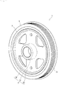
- FIG. 1 and FIG. 2 The torsional damper of the invention is first described using FIG. 1 and FIG. 2 .
- FIG. 1 is a schematic perspective view illustrating an embodiment of the torsional damper of the invention
- FIG. 2 is a schematic cross-sectional perspective view of the torsional damper shown in FIG. 1 .
- a torsional damper 1 of the embodiment illustrated in FIG. 1 and FIG. 2 can be used by being attached to an end of a crankshaft of an engine in a vehicle or the like.
- the torsional damper 1 has the function of absorbing torsional resonance of the crankshaft and the function of suppressing engine vibration and noise. Further, the torsional damper may also serve as a drive pulley (crank pulley) that transmits power from the rotating crankshaft to auxiliary devices through a belt.
- the torsional damper 1 has a hub 3, a vibration ring 5, and a rubber ring 7.
- the hub 3 includes a boss part 31, a stay part 33, and a rim part 35.
- the boss part 31 is provided at a central portion of the hub 3 in its radial direction.
- the boss part 31 is fixed to an end of the crankshaft (rotating shaft) and the hub 3 is driven to rotate around an axis of rotation X.
- the stay part 33 extends in the radial direction from the boss part 31.
- the rim part 35 is provided on an outer peripheral side of the stay part 33.
- the rim part 35 has a cylindrical shape and the vibration ring 5 is connected to an outer peripheral side of the rim part 35 via the rubber ring 7.
- An outer peripheral surface of the rim part 35 is present on a circumference around the axis of rotation X.
- a metallic material such as cast iron or the like can be used as a raw material to form each of the boss part 31, the stay part 33, and the rim part 35.
- each of the boss part 31, the stay part 33, and the rim part 35 is preferably made of particularly flake graphite cast iron, spheroidal graphite cast iron, hot-rolled steel sheet for use in automobile structures or the like.
- flake graphite cast iron examples include FC100, FC150, FC200, FC250, FC300 and FC350.
- spheroidal graphite cast iron examples include FCD350-22, FCD350-22L, FCD400-18, FCD400-18L, FCD400-15, FCD450-10, FCD500-7, FCD600-3, FCD700-2, FCD800-2, FCD400-18A, FCD400-18AL, FCD400-15A, FCD500-7A, and FCD600-3A.
- hot-rolled steel sheet for use in automobile structures examples include SAPH310, SAPH370, SAPH410, and SAPH440.
- the vibration ring 5 is placed outside the hub 3 in its radial direction.
- An inner peripheral surface of the vibration ring 5 has a larger diameter than the outer peripheral surface of the hub 3.
- the inner peripheral surface is present on a circumference around the crankshaft (axis of rotation X).
- pulley grooves 51 over which the belt is stretched are formed at an outer peripheral surface of the vibration ring 5.
- the pulley grooves 51 serve as a pulley for power transmission.
- a metallic material such as cast iron or the like can be used as a raw material to form the vibration ring 5.
- the vibration ring 5 is preferably made of flake graphite cast iron. This is because the flake graphite cast iron has high vibration absorption performance and is also excellent in abrasion resistance. Examples of the flake graphite cast iron that may be illustrated include FC100, FC150, FC200, FC250, FC300 and FC350.
- the rubber ring 7 is inserted into a gap portion between the outer peripheral surface of the hub 3 and the inner peripheral surface of the vibration ring 5.
- the rubber ring 7 serves to reduce torsional vibration of the crankshaft that occurs during driving in a vehicle or the like, thus preventing breakage, or to reduce noise and vibration due to engine vibration.
- the rubber ring 7 can be obtained by forming a rubber composition primarily composed of an ethylene/propylene/diene ternary copolymer (EPDM) and additionally containing preferably carbon black and process oil into a cylindrical shape or other shapes through vulcanization using, for instance, a conventionally known method.
- EPDM ethylene/propylene/diene ternary copolymer
- the rubber composition contains EPDM in an amount of preferably 10 to 60 mass, more preferably 15 to 55 mass%, even more preferably 20 to 50 mass%, and still more preferably 30 to 50 mass%.
- the carbon black content with respect to 100 parts by mass of EPDM is preferably 40 to 130 parts by mass, more preferably 50 to 100 parts by mass, and even more preferably 60 to 80 parts by mass.
- the rubber composition may contain Chinese white, stearic acid, an antioxidant, a peroxide, a crosslinking agent or other components.
- the loss factor (tan ⁇ ) of the rubber ring 7 at a surface temperature of 60 ⁇ 5°C is 0.18 or more, preferably 0.18 to 0.40, more preferably 0.19 to 0.35, and even more preferably 0.20 to 0.28.
- the loss factor (tan ⁇ ) at the surface temperature of 60 ⁇ 5°C means a value obtained by measurement with a high frequency vibration tester according to the resonance point tracking process (natural frequency measurement).
- the measurement according to the resonance point tracking process is performed under the following conditions:
- the torsional damper can be manufactured for instance by a method to be described below.
- a hub 30 and a vibration ring 50 as shown in FIG. 3 are prepared, and a torque improving liquid is applied thereto by a means such as spraying.
- a solution obtained by dissolving a silane coupling agent in a hydrocarbon solution (solvent) such as toluene or xylene can be mainly used as the torque improving liquid.
- the torque improving liquid is preferably applied to portions of the hub 30 and the vibration ring 50 which come into contact with the rubber ring 70, specifically the inner peripheral surface of the vibration ring 50 and the outer peripheral surface of the rim part of the hub 30.
- the rubber ring having a fitting liquid applied thereto is press fit into a space (gap portion 80) between the hub 30 and the vibration ring 50 using a press fitting tool such as a press machine.
- the space in the gap portion 80 preferably has a narrower width than the thickness of the rubber ring 70.
- the ratio of the thickness of the rubber ring 70 to the width of the space in the gap portion 80 is preferably about 0.6 to 0.9.
- the rubber ring is present in a compressed state between the outer peripheral surface of the hub and the inner peripheral surface of the vibration ring.
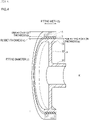
- the inventor prepared torsional dampers of various structures which were different in vibration ring thickness (a), fitting width (b), rubber thickness (c), fitting diameter (d), and hub fitting portion thickness (e), and examined influences on the rubber ring temperature.
- the vibration ring thickness (a) as used herein refers to, as shown in FIG. 4 , a thickness of the vibration ring 5 in its radial direction (direction perpendicular to the axis of rotation X).
- the vibration ring thickness (a) is not fixed in the radial direction of the vibration ring 5 as in the embodiment shown in FIG. 2 , the thickness of the vibration ring 5 in its radial direction is measured at randomly selected 10 points and a value obtained by averaging measured values is taken as the vibration ring thickness (a).
- the fitting width (b) refers to, as shown in FIG. 4 , a length of the rim part 35 of the hub 3 in the direction of the axis of rotation X. In a case where the fitting width (b) is not fixed in the direction of the axis of rotation X, the length of the longest portion of the rim part 35 of the hub 3 in the direction of the axis of rotation X is taken as the fitting width (b).
- the rubber thickness (c) refers to, as shown in FIG. 4 , a thickness of the rubber ring 7 in its radial direction (direction perpendicular to the axis of rotation X). In a case where the rubber thickness (c) is not fixed in the radial direction of the rubber ring 7 as in the embodiment shown in FIG. 2 , the thickness of the rubber ring 7 in its radial direction is measured at randomly selected 10 points and a value obtained by averaging measured values is taken as the rubber thickness (c).
- the fitting diameter (d) refers to, as shown in FIG. 4 , a diameter of the hub 3 up to the outer peripheral surface of the rim part 35.
- the fitting diameter (d) refers to a diameter having the smallest value. Therefore, in a case where the rim part 35 is meandering with respect to the direction of the axis of rotation X as in the embodiment shown in FIG. 2 , the fitting diameter refers to a diameter at a point on the outer peripheral surface which is closest to the axis of rotation X (center point in the direction of the axis of rotation X in the case of FIG. 2 ).
- the hub fitting portion thickness (e) refers to, as shown in FIG. 4 , a thickness of the rim part 35 of the hub 3 in its radial direction (direction perpendicular to the axis of rotation X).
- the hub fitting portion thickness (e) as used herein refers to a thickness of the rim part 35 except the portion where the rim part 35 is connected to the stay part 33. In a case where the hub fitting portion thickness (e) is not fixed in the direction perpendicular to the axis of rotation X as in the embodiment shown in FIG.
- the thickness of the rim part 35 (except the portion where the rim part 35 is connected to the stay part 33) in its radial direction is measured at randomly selected 10 points in the direction perpendicular to the axis of rotation X and a value obtained by averaging measured values is taken as the hub fitting portion thickness (e) .
- the inventor prepared torsional dampers of various structures according to the embodiment shown in FIG. 4 which were different in vibration ring thickness (a), fitting width (b), rubber thickness (c), fitting diameter (d), and hub fitting portion thickness (e), and subjected each of the torsional dampers to the above-mentioned resonance point tracking process to measure the maximum attained surface temperature (Tmax) of the rubber ring during the process.
- the measurement of the maximum attained surface temperature (Tmax) of the rubber ring according to the resonance point tracking process is performed under the following conditions:
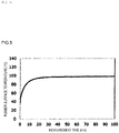
- the surface temperature of the rubber ring of the torsional damper was measured using a non-contact surface thermometer while performing the resonance point tracking process as described above.
- FIG. 5 An exemplary measurement result is shown in FIG. 5 .
- the surface temperature of the rubber ring (vertical axis in FIG. 5 ) is gradually increased from the start of the test and is saturated after the passage of about 30 minutes.
- the surface temperature of the rubber ring at the time of saturation was taken as the maximum attained surface temperature (Tmax) of the rubber ring in the torsional damper of the relevant structure.
- the inventor subjected the torsional dampers of various structures which were different in vibration ring thickness (a), fitting width (b), rubber thickness (c), fitting diameter (d), and hub fitting portion thickness (e) to the resonance point tracking process, thus measuring the maximum attained surface temperature (Tmax) of the rubber ring during the process.
- Tmax maximum attained surface temperature of the rubber ring depends strongly on the vibration ring thickness (a) and the temperature of the rubber ring is not increased in a region shown in FIG. 6 .
- the region is expressed by the following formulae: Tmax ⁇ ⁇ 2 .7 a + 124.3 , and 1.6 ⁇ a .
- Plotted points in FIG. 6 are data showing a relationship between the vibration ring thickness (a, unit: mm) measured by the above-mentioned resonance point tracking process and the maximum attained surface temperature (Tmax, unit: °C) of the rubber ring.
- the data are shown in Table 1.
- the maximum attained surface temperature (Tmax) of the rubber ring is lower than 120°C.
- the rubber ring used in the invention is a rubber ring which is made of a rubber composition primarily composed of EPDM and has a loss factor (tan ⁇ ) of 0.18 or more at the surface temperature of 60 ⁇ 5°C, and the rubber ring like this is not readily broken when the maximum attained surface temperature (Tmax) is 120°C or less.
- the torsional damper of the invention preferably satisfies Formula (3).
- the torsional damper of the invention preferably satisfies Formula (4).
- the vibration ring thickness (a) is 1.6 mm or more according to Formula (2) but is more preferably 2.0 mm or more.
- the vibration ring thickness (a) is preferably 10.0 mm or less, more preferably 9.0 mm or less, even more preferably 8.5 mm or less, and still more preferably 8.0 mm or less.
- the torsional damper of the invention described above in detail is much less likely to cause rubber ring breakage due to heat generation.
Landscapes
- Engineering & Computer Science (AREA)
- General Engineering & Computer Science (AREA)
- Physics & Mathematics (AREA)
- Acoustics & Sound (AREA)
- Aviation & Aerospace Engineering (AREA)
- Mechanical Engineering (AREA)
- Pulleys (AREA)
Applications Claiming Priority (2)
| Application Number | Priority Date | Filing Date | Title |
|---|---|---|---|
| JP2019230166 | 2019-12-20 | ||
| PCT/JP2020/043858 WO2021124819A1 (fr) | 2019-12-20 | 2020-11-25 | Amortisseur de torsion |
Publications (2)
| Publication Number | Publication Date |
|---|---|
| EP4080084A1 true EP4080084A1 (fr) | 2022-10-26 |
| EP4080084A4 EP4080084A4 (fr) | 2024-01-24 |
Family
ID=76476584
Family Applications (1)
| Application Number | Title | Priority Date | Filing Date |
|---|---|---|---|
| EP20903215.0A Pending EP4080084A4 (fr) | 2019-12-20 | 2020-11-25 | Amortisseur de torsion |
Country Status (6)
| Country | Link |
|---|---|
| US (1) | US11913515B2 (fr) |
| EP (1) | EP4080084A4 (fr) |
| JP (1) | JP7318001B2 (fr) |
| KR (1) | KR20220075430A (fr) |
| CN (1) | CN114599895A (fr) |
| WO (1) | WO2021124819A1 (fr) |
Families Citing this family (2)
| Publication number | Priority date | Publication date | Assignee | Title |
|---|---|---|---|---|
| CN114599896A (zh) * | 2019-12-20 | 2022-06-07 | Nok株式会社 | 扭转减振器 |
| CN114616409A (zh) * | 2019-12-20 | 2022-06-10 | Nok株式会社 | 扭转减振器 |
Family Cites Families (13)
| Publication number | Priority date | Publication date | Assignee | Title |
|---|---|---|---|---|
| JP2000320613A (ja) * | 1999-05-14 | 2000-11-24 | Nok Vibracoustic Kk | トルク変動吸収ダンパ |
| US6386065B1 (en) * | 2000-07-25 | 2002-05-14 | The Gates Corporation | Dual ring damper |
| JP2007009073A (ja) | 2005-06-30 | 2007-01-18 | Nissin Kogyo Co Ltd | ダンパー用ゴム部材 |
| JP2015129543A (ja) * | 2014-01-07 | 2015-07-16 | Nok株式会社 | トルク変動吸収ダンパ |
| CN204283528U (zh) * | 2014-10-28 | 2015-04-22 | 宁波吉利罗佑发动机零部件有限公司 | 一种vvt驱动器 |
| KR20160126687A (ko) * | 2015-04-24 | 2016-11-02 | 엔오케이 가부시키가이샤 | 토크 변동 흡수 댐퍼 |
| JP6923315B2 (ja) * | 2016-12-13 | 2021-08-18 | 株式会社フコク | トーショナルダンパ |
| JP2018105313A (ja) * | 2016-12-22 | 2018-07-05 | Nok株式会社 | トルク変動吸収ダンパ |
| CN106894298B (zh) * | 2017-01-10 | 2018-12-21 | 西南交通大学 | 浮置板轨道隔振器 |
| JP2018115666A (ja) * | 2017-01-16 | 2018-07-26 | Nok株式会社 | トーショナルダンパ |
| CN110582538B (zh) | 2017-04-21 | 2022-05-06 | Nok株式会社 | 扭振减振器用橡胶组合物以及扭振减振器 |
| JP6882067B2 (ja) * | 2017-05-23 | 2021-06-02 | 株式会社フコク | トーショナルダンパ |
| JP7021963B2 (ja) * | 2018-01-30 | 2022-02-17 | 株式会社フコク | ゴム部材およびそれを用いたダンパー |
-
2020
- 2020-11-25 EP EP20903215.0A patent/EP4080084A4/fr active Pending
- 2020-11-25 CN CN202080073425.9A patent/CN114599895A/zh active Pending
- 2020-11-25 WO PCT/JP2020/043858 patent/WO2021124819A1/fr active Search and Examination
- 2020-11-25 US US17/780,126 patent/US11913515B2/en active Active
- 2020-11-25 KR KR1020227016065A patent/KR20220075430A/ko not_active Application Discontinuation
- 2020-11-25 JP JP2021565413A patent/JP7318001B2/ja active Active
Also Published As
| Publication number | Publication date |
|---|---|
| US11913515B2 (en) | 2024-02-27 |
| KR20220075430A (ko) | 2022-06-08 |
| EP4080084A4 (fr) | 2024-01-24 |
| JP7318001B2 (ja) | 2023-07-31 |
| CN114599895A (zh) | 2022-06-07 |
| JPWO2021124819A1 (fr) | 2021-06-24 |
| WO2021124819A1 (fr) | 2021-06-24 |
| US20220412432A1 (en) | 2022-12-29 |
Similar Documents
| Publication | Publication Date | Title |
|---|---|---|
| EP4080084A1 (fr) | Amortisseur de torsion | |
| EP4080086A1 (fr) | Amortisseur de torsion | |
| KR102452227B1 (ko) | 토셔널 댐퍼 | |
| CN110678669A (zh) | 扭转减振器 | |
| WO2018079076A1 (fr) | Élément amortisseur en caoutchouc et amortisseur de torsion | |
| EP4080083A1 (fr) | Amortisseur de torsion | |
| EP4080085A1 (fr) | Amortisseur de torsion | |
| JP2019147906A (ja) | ゴム部材およびそれを用いたダンパー | |
| JP7377696B2 (ja) | トーショナルダンパ | |
| JPH11159576A (ja) | ダンパ | |
| JP6817539B2 (ja) | トーショナルダンパ | |
| US20190085934A1 (en) | Torsional vibration damper with low elastomer content | |
| JP7496301B2 (ja) | トルク変動吸収ダンパー | |
| JP7542479B2 (ja) | トーショナルダンパ | |
| KR20160126687A (ko) | 토크 변동 흡수 댐퍼 | |
| JP2005009551A (ja) | トーショナルダンパ |
Legal Events
| Date | Code | Title | Description |
|---|---|---|---|
| STAA | Information on the status of an ep patent application or granted ep patent |
Free format text: STATUS: THE INTERNATIONAL PUBLICATION HAS BEEN MADE |
|
| PUAI | Public reference made under article 153(3) epc to a published international application that has entered the european phase |
Free format text: ORIGINAL CODE: 0009012 |
|
| STAA | Information on the status of an ep patent application or granted ep patent |
Free format text: STATUS: REQUEST FOR EXAMINATION WAS MADE |
|
| 17P | Request for examination filed |
Effective date: 20220603 |
|
| AK | Designated contracting states |
Kind code of ref document: A1 Designated state(s): AL AT BE BG CH CY CZ DE DK EE ES FI FR GB GR HR HU IE IS IT LI LT LU LV MC MK MT NL NO PL PT RO RS SE SI SK SM TR |
|
| DAV | Request for validation of the european patent (deleted) | ||
| DAX | Request for extension of the european patent (deleted) | ||
| REG | Reference to a national code |
Ref country code: DE Ref legal event code: R079 Free format text: PREVIOUS MAIN CLASS: F16F0015120000 Ipc: F16F0015126000 |
|
| A4 | Supplementary search report drawn up and despatched |
Effective date: 20231221 |
|
| RIC1 | Information provided on ipc code assigned before grant |
Ipc: F16F 15/126 20060101AFI20231215BHEP |