EP4079674B1 - Handhabungsvorrichtung mit steuerung - Google Patents
Handhabungsvorrichtung mit steuerung Download PDFInfo
- Publication number
- EP4079674B1 EP4079674B1 EP22168480.6A EP22168480A EP4079674B1 EP 4079674 B1 EP4079674 B1 EP 4079674B1 EP 22168480 A EP22168480 A EP 22168480A EP 4079674 B1 EP4079674 B1 EP 4079674B1
- Authority
- EP
- European Patent Office
- Prior art keywords
- handling device
- designed
- operating
- operating element
- support
- Prior art date
- Legal status (The legal status is an assumption and is not a legal conclusion. Google has not performed a legal analysis and makes no representation as to the accuracy of the status listed.)
- Active
Links
Images



Classifications
-
- B—PERFORMING OPERATIONS; TRANSPORTING
- B66—HOISTING; LIFTING; HAULING
- B66D—CAPSTANS; WINCHES; TACKLES, e.g. PULLEY BLOCKS; HOISTS
- B66D3/00—Portable or mobile lifting or hauling appliances
- B66D3/18—Power-operated hoists
-
- B—PERFORMING OPERATIONS; TRANSPORTING
- B66—HOISTING; LIFTING; HAULING
- B66F—HOISTING, LIFTING, HAULING OR PUSHING, NOT OTHERWISE PROVIDED FOR, e.g. DEVICES WHICH APPLY A LIFTING OR PUSHING FORCE DIRECTLY TO THE SURFACE OF A LOAD
- B66F9/00—Devices for lifting or lowering bulky or heavy goods for loading or unloading purposes
- B66F9/06—Devices for lifting or lowering bulky or heavy goods for loading or unloading purposes movable, with their loads, on wheels or the like, e.g. fork-lift trucks
- B66F9/061—Devices for lifting or lowering bulky or heavy goods for loading or unloading purposes movable, with their loads, on wheels or the like, e.g. fork-lift trucks characterised by having a lifting jib
-
- B—PERFORMING OPERATIONS; TRANSPORTING
- B66—HOISTING; LIFTING; HAULING
- B66F—HOISTING, LIFTING, HAULING OR PUSHING, NOT OTHERWISE PROVIDED FOR, e.g. DEVICES WHICH APPLY A LIFTING OR PUSHING FORCE DIRECTLY TO THE SURFACE OF A LOAD
- B66F9/00—Devices for lifting or lowering bulky or heavy goods for loading or unloading purposes
- B66F9/06—Devices for lifting or lowering bulky or heavy goods for loading or unloading purposes movable, with their loads, on wheels or the like, e.g. fork-lift trucks
- B66F9/075—Constructional features or details
- B66F9/12—Platforms; Forks; Other load supporting or gripping members
- B66F9/18—Load gripping or retaining means
- B66F9/181—Load gripping or retaining means by suction means
Definitions
- the invention relates to a handling device for handling and possibly transporting objects.
- Hand-held handling devices can be used to move the objects, which allow for a high degree of flexibility when loading.
- Hose lifters with suction grippers arranged at the end of a lifting hose can be used as lifting aids.
- Crane-like constructions are also known.
- EP289042A1 For example, a stationary lifting aid is known, in which a support cable is guided along a horizontally aligned, laterally pivoting boom.
- a vacuum gripper can be arranged on the support cable to fix the objects to the device. The operator can After picking up, push or pull by hand to move it to its destination and set it down there.
- Industrial trucks are often used to move objects over longer distances, e.g. order pickers, forklifts or pallet trucks.
- EP 3 002 247 A discloses the preamble of claim 1.
- the present invention is based on the object of providing a handling device which can be operated comfortably and safely, in particular during changing activities.
- the object is achieved with a handling device with the features of claim 1.
- the handling device comprises a support that extends along a vertical support axis when the handling device is operated as intended.
- a movable boom is arranged on the support, which comprises, for example, several cantilever members that are movably connected to one another.
- the support and optionally the boom are controllable, i.e. the configuration and position can be adjusted by a drive.
- the support is height-adjustable in a controlled manner.
- the boom can, for example, change its configuration in a controllable manner.
- the handling device comprises a controllable lifting tool, in particular a hose lifter, arranged on the boom.
- the lifting tool can preferably be arranged on a connecting section of the last cantilever member.
- the handling device comprises a controllable gripping means for fixing objects, in particular a suction gripper, which is arranged on the lifting tool in such a way that the gripping means and an object fixed thereby can be raised and lowered.
- the support is height-adjustable.
- the boom can be rotatably and/or translatorily movable relative to the support.
- the support can also be rotatably movable.
- the boom can be rotatably movable about the cantilever direction and/or about the support axis.
- the boom can, for example, have two booms which are connected to one another in an articulated manner.
- the first cantilever member and/or the at least one further cantilever member can be rotatably and/or translatorily movable relative to one another and/or to the support.
- the handling device provides at least one controllable drive device, which is designed to adjust the height of the support and optionally to move the boom.
- the at least one drive device can also be designed to move the support.
- the drive device can in particular be designed to move the first cantilever member and/or the at least one further cantilever member.
- the handling device further provides an operating device for operating the handling device by an operator, which comprises a holding section that can be grasped by the operator and at least one operating element; depending on the functionalities, several operating elements can also be provided.
- an operator By gripping the holding section, the operator can guide and handle the handling device, in particular the gripping means and a gripped object.
- the holding section is arranged on the gripping means, on the lifting tool or between the lifting tool and the gripping means.
- the gripping means and a gripped object can thus be guided easily and safely due to the proximity of the holding section to the gripping means.
- the at least one operating element (or the multiple operating elements) is arranged on the gripping means, on the lifting tool or between the gripping means and the lifting tool.
- the operating device is designed such that the gripping means and the lifting tool as well as the support and optionally the boom can be controlled by means of the at least one operating element (or by means of the several operating elements).
- a further drive device is preferably provided for adjusting the lifting tool and/or the gripping means.
- the operating device acts in the manner of a control device with corresponding drive devices for the support and optionally for the boom and, if applicable, for the lifting tool and/or the gripping device.
- one operating element is designed to control one function each, e.g. one operating element to control the height of the support, one operating element to control the lifting tool, if applicable one operating element to control the gripping device and if applicable one operating element to control the boom.
- the handling device with its various functions, such as gripping and raising and lowering the lifting tool and the support, can be operated by the operator in the area of the gripping device. The operator therefore does not have to leave his position or put down the gripped object and/or the gripping device in order to change the configuration of the handling device.
- the boom preferably comprises a plurality of cantilever members, wherein a first cantilever member is arranged on the support in a rotationally and/or displacement-proof manner and extends in a first cantilever plane transversely to the support along a first cantilever direction, and wherein at least one further cantilever member extending in a further cantilever plane is arranged pivotably with a joint on the previous cantilever member.
- the joints and/or the cantilever members are preferably designed such that the subsequent cantilever planes are each located below the previous cantilever planes.
- the operating device in particular the holding section and the at least one operating element, is designed such that the operator can actuate the at least one operating element when holding the holding section.
- the holding section can be designed such that the operator can grip the holding section with one hand or with both hands, in which case the holding section and the at least one operating element are designed such that the operator can actuate the at least one operating element with one hand or with both hands when holding the holding section.
- the holding section is designed such that it can be grasped by the operator with one hand, and if the at least one operating element is designed and/or positioned such that the operator can simultaneously grasp the handle and actuate the operating element with one hand.
- the handle is designed as a grippable handle bar which extends essentially vertically, in particular essentially parallel to the support axis, when the handling device is operated as intended.
- the handle bar can be designed to be essentially circular or elliptical in cross section in order to fit well in the hand.
- the handle bar can also be individually adapted to at least one hand of the operator.
- the at least one operating element can be designed as an operating button, sensor field and/or rotary or sliding control.
- the operating element can preferably be actuated by exerting pressure along an actuation direction, wherein the actuation direction can be designed essentially horizontally, in particular essentially orthogonal to the support axis. This enables an operator to grip the holding section and to actuate the operating element when holding it, e.g. by applying pressure with the thumb and/or a finger.
- the operating device is designed such that by means of the at least one operating element the at least one drive device for adjusting the height of the support and optionally controllable for moving the boom, in particular for moving the first cantilever member and/or the at least one further cantilever member.
- the operating device can provide a connecting device (e.g. control cable or bus connection) for connecting the at least one operating element and the at least one drive device, which is arranged in particular within the handling device and preferably within the support and/or the boom.
- the operating device is advantageously designed such that the gripping means for securing an object can be controlled by means of the at least one operating element.
- the gripping means can be designed, for example, as a mechanical gripper with at least one jaw for securing the object. By actuating the at least one operating element, the jaw is moved, in particular opened and closed.
- the operating device can interact with a drive device of the gripping means.
- the gripping means can also be designed as a vacuum gripper with at least one suction point for sucking in an object. The operating device can then be designed to control a valve device for controlling the vacuum supply for the vacuum gripper.
- the operating device is also designed in such a way that the lifting tool can be controlled for raising and lowering by actuating the at least one operating element.
- the lifting tool can be designed, for example, as a lifting hose, be designed as a rope or chain hoist or as a telescopic column.
- the handling device can comprise a controllable negative pressure generator, in particular a controllable negative pressure pump, for providing the negative pressure and/or a controllable valve device, in particular with at least one controllable valve.
- the valve preferably serves to control the application of negative pressure to the lifting tool and/or the gripping means.
- the lifting tool and/or the gripping means can then be controlled with the valve device.
- the operating device can be designed such that the negative pressure generator and/or the valve device can be controlled by means of the at least one operating element.
- the operating device can be designed such that the negative pressure generator can be switched on and off and the power of the negative pressure generator can be adjusted by means of the at least one operating element.
- the operating device can be designed such that at least one valve of the valve device can be opened and closed by means of the at least one operating element.
- the support and/or the boom, in particular the first cantilever member and/or the at least one further cantilever member preferably have channels, in particular internal channels, for conveying media and/or data.
- the support and/or the Booms, in particular the first cantilever member and/or the at least one further cantilever member are preferably designed as hollow profiles, with the internal cavities of the hollow profiles forming the aforementioned channels.
- This provides an internal pressure control system for the lifting tool and/or the gripping means and/or an internal data control system for the operating device and avoids interfering contours caused by hoses and/or lines.
- the channels preferably fluidically connect the vacuum generator to the lifting tool and/or to the gripping tool.
- the channels preferably signal-connect the operating device to the vacuum generator and/or to the at least one drive device.
- the operating device is designed such that a peripheral device interacting with the handling device or provided in the vicinity of the handling device, in particular a conveyor belt, a robot and/or a production station, can be controlled by means of the at least one operating element.
- the handling device is designed as a mobile handling device for arranging on and/or for connecting to an industrial truck.
- the industrial truck can in particular be designed as an order picker, a forklift or a pallet truck.
- the handling device can preferably comprise a base housing with a central longitudinal axis running parallel to the cantilever direction and with a transverse axis running orthogonal to the central longitudinal axis and parallel to the first cantilever plane.
- the support is preferably arranged eccentrically with respect to the central longitudinal axis on the base housing, in particular in a rotationally and/or displacement-proof manner. In this respect, the support is arranged on the base housing at a distance from the central longitudinal axis along the transverse axis. Accordingly, the handling device can be easily driven under and moved with an industrial truck or with a handling fork of an industrial truck.
- the base housing preferably has at least one tine holder for at least one tine of a handling fork of an industrial truck, wherein the tine holder is designed in particular in the manner of a tine overshoe.
- the base housing and/or the tine holder is preferably designed in such a way that the base housing can be driven under with the industrial truck and the at least one tine can be inserted into the at least one tine holder. This allows the handling device to be easily transported using the industrial truck.
- the at least one drive device and/or the vacuum pump can preferably be arranged in the base housing.
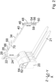
- a mobile handling device 10 with an industrial truck 12 designed as a forklift is shown.
- the forklift 12 has a handling fork 14 with two tines 16.
- the handling device 10 is designed to be connected to or attached to the forklift 12 or to a lifting truck.
- a coordinate system with the axes X, Y and Z is also shown.
- the forklift 12 is moved along an insertion direction 18, which runs in the positive X-direction, to attach the handling device 10.
- the handling fork 14 is located inside or underneath the handling device 10 and is then raised in the positive Z direction.
- the handling fork 14 is lowered in the negative Z direction so that the handling device 10 stands on the ground.
- the handling fork 14 is moved against the insertion direction 18.
- the mobile handling device 10 comprises, as shown in particular in Fig. 2 can be seen a base housing 20 with two tine holders 21 extending along the X-axis.
- the handling device 10 comprises a support 24 which extends along a support axis 22 which is vertical when the handling device 10 is operated as intended.
- the support 24 is designed as a column which is telescopic and therefore height-adjustable.
- a boom 26 is arranged on the support 24.
- the boom 26 comprises a first cantilever member 28 which is fastened to the support 24 in a rotationally and displacement-proof manner and which extends in a first cantilever plane 30 along a first cantilever direction 32.
- the boom 26 further comprises a second cantilever member 34 which is mounted on the first cantilever member 28 by means of a first pivot joint 36 so as to be pivotable about a first axis of rotation 37 and which extends in a second cantilever plane 38.
- the boom 26 further comprises a third cantilever member 40, which is pivotable about a second axis of rotation 43 by means of a second pivot joint 42.
- the second cantilever member 34 is mounted and extends in a third cantilever plane 44.
- the cantilever members 28, 34, 40 and the swivel joints 36, 42 are designed such that the first cantilever plane 30 is arranged above the second cantilever plane 38 and the third cantilever plane 44, that the second cantilever plane 38 is arranged above the third cantilever plane 44 and that the first cantilever plane 30, the second cantilever plane 38 and the third cantilever plane 44 run parallel to one another.
- Fig. 2 , 3a, 3b the mobility of the support 24 and the boom 26 is indicated by means of the double-sided arrows.
- a connecting section 46 for coupling a lifting tool 48 is provided on the third cantilever member 40.
- the lifting tool 48 is designed as a controllable hose lifter.
- a controllable suction gripper 50 for fixing objects 52 is indirectly arranged on the lifting tool 48 in such a way that the suction gripper 50 and an object 52 fixed thereby can be raised and lowered.
- an operating device 54 is provided for operating the handling device 10 by an operator.
- the operating device 54 shown comprises a holding section 56 that can be grasped by the operator and six operating elements 58.
- the holding section 56 is designed as a grippable handle bar that extends essentially vertically and has an elliptical shape in cross section.
- the holding section 56 can be grasped by the operator with one hand.
- the operating elements 58 are arranged on the operating device 54 in such a way that the The operator can operate the operating elements 58 when holding the holding section 56.
- the six operating elements 58 are each designed as a control button, so that the operator can operate the operating elements 58 by applying pressure along an actuation direction 60 using a finger and/or a thumb.
- the actuation direction 60 is essentially transverse to the support axis 22.
- the handling device 10 comprises a controllable vacuum generator 62 and a controllable drive device 64.
- the lifting tool 48 and the suction gripper 50 can be driven by means of vacuum.
- the vacuum generator 62 is designed as a vacuum pump and for providing the vacuum.
- the vacuum pump 62 is preferably arranged in the base housing 20.
- the handling device 10 comprises within the base housing 20, the support 24 and the boom 26 a controllable valve device 66 assigned to the operating device 54 with valves (not shown) for directing the vacuum.
- the drive device 64 interacts with the support 24 and with the cantilever members 28, 34, 40, so that the drive device 64 drives the support 24 for height adjustment and the cantilever members 28, 34, 40 for pivoting.
- the drive device 64 can move the support 24 and the boom 26 independently after actuating a control element 58 or can assist the operator in guiding the support 24 and the boom 26 so that the movement requires only a small amount of effort from the operator.
- Drive device 64 is preferably arranged in the base housing 20 or on the boom 26.
- the handling device 10 also comprises an internal pressure control system 68 and an internal data control system 70, which are arranged in the hollow support 24 and in the hollow boom 26.
- the pressure control system 68 fluidically connects the vacuum pump 62 to the lifting tool 48 and to the suction gripper 50.
- the data control system 70 connects the operating device 54 to the vacuum pump 62 and the drive device 64 by means of signals.
- the operating device 54 is designed such that the operator can actuate the operating elements 58 when holding the holding section 56.
- the operating elements 58 can be used to control the vacuum pump 62, the drive device 64 and the valve device 66 as well as peripheral devices that interact with the handling device 10 and are provided in the vicinity of the handling device 10. Consequently, the operating device is designed such that the operating elements 58 can be used to switch the handling device 10, in particular the vacuum pump 62 and the drive device 64, on and off, the support 24 can be adjusted in height, the cantilever members 28, 34, 40 can be pivoted by more than 360° and the lifting tool 48 can be compressed and expanded parallel to the support axis 22.
- the operating device 54 is designed such that the operating elements 58 can be used to Suction gripper 50 and thus a fixed object 52 can be raised and lowered and a negative pressure can be generated in the suction gripper 50 to fix the object 52. Furthermore, the operating device 54 is designed so that the power of the negative pressure generator 62 and the drive device 64 can be adjusted by means of the operating elements 58 and the valves of the valve device 66 can be opened and closed.
Landscapes
- Engineering & Computer Science (AREA)
- Transportation (AREA)
- Structural Engineering (AREA)
- Mechanical Engineering (AREA)
- Civil Engineering (AREA)
- Life Sciences & Earth Sciences (AREA)
- Geology (AREA)
- Forklifts And Lifting Vehicles (AREA)
Description
- Die Erfindung betrifft eine Handhabungsvorrichtung zum Handhaben und ggf. Transportieren von Objekten.
- In Produktions- oder Logistikumgebungen gibt es oftmals eine Vielzahl von Handhabungsstationen, an denen Objekte z.B. aus einem Lagerregal auf eine Palette bewegt werden müssen. Zum Bewegen der Objekte können handgeführte Handhabungsvorrichtungen zum Einsatz kommen, die eine hohe Flexibilität beim Verladen ermöglichen. Als Hebehilfen können Schlauchheber mit endständig an einem Hubschlauch angeordneten Sauggreifern zum Einsatz kommen. Auch kranartige Konstruktionen sind bekannt. Aus der
EP289042A1 -
EP 3 002 247 A offenbart den Oberbegriff von Anspruch 1. - Aus der
EP 3 002 247 A1 ist ein Gabelstapler mit einer Stützstruktur und einem Ausleger bekannt, wobei an dem Ausleger ein Handhabungsarm mit Mitteln zum Greifen einer Last angeordnet ist. Aus derDE 10 2015 112 125 A1 ist ein Kommissioniergerät mit einem Manipulator-Knickarm und einem Greifer bekannt. Aus derDE 20 2020 104 055 U1 ist ein Manipulator zum Anordnen an einem Flurförderfahrzeug bekannt. Aus derWO 98/43911 A1 DE 10 2018 121 726 A1 ist ein Flurförderfahrzeug umfassend eine Kommissioniervorrichtung bekannt. Aus derJP 2011 119556 A - Beim Verlagern der mit der Handhabungsvorrichtung gehaltenen Objekte von Hand sind hohe Anforderungen an die Sicherheit zu stellen, um zu gewährleisten, dass z.B. keine Objekte herunterfallen. Dazu sind die Bediener angehalten, nur die Handhabungsvorrichtung zu bedienen und dabei keine weiteren Tätigkeiten auszuführen. Dies bedingt, dass der Bediener die Objekte ablegen muss, wenn er z.B. die Handhabungsvorrichtung an- und ausschalten möchte oder weitere Peripherie bedienen möchte. Damit geht ein hoher Zeitaufwand einher, insbesondere wenn der Bediener mehrere verschiedene Tätigkeiten hintereinander absolviert.
- Der vorliegenden Erfindung liegt die Aufgabe zugrunde, eine Handhabungsvorrichtung bereitzustellen, welche insbesondere bei wechselnden Tätigkeiten komfortabel und sicher bedient werden kann.
- Die Aufgabe wird mit einer Handhabungsvorrichtung mit den Merkmalen des Anspruchs 1 gelöst. Die Handhabungsvorrichtung umfasst eine sich bei bestimmungsgemäßen Betrieb der Handhabungsvorrichtung entlang einer senkrechten Stützachse erstreckende Abstützung. An der Abstützung ist ein beweglicher Ausleger angeordnet, welcher z.B. mehrere miteinander beweglich verbundene Auskragglieder umfasst. Die Abstützung und optional der Ausleger sind steuerbar, d.h. Konfiguration und Position ist angetrieben einstellbar. Die Abstützung ist kontrolliert höhenverstellbar. Der Ausleger kann z.B. steuerbar seine Konfiguration ändern.
- Zudem umfasst die Handhabungsvorrichtung ein an dem Ausleger angeordnetes steuerbares Hubwerkzeug, insbesondere Schlauchheber. Das Hubwerkzeug kann vorzugsweise an einem Anschlussabschnitt des letzten Auskragglieds angeordnet sein.
- Ferner umfasst die Handhabungsvorrichtung ein steuerbares Greifmittel zum Fixieren von Objekten, insbesondere Sauggreifer, das derart an dem Hubwerkzeug angeordnet ist, dass das Greifmittel und ein damit fixiertes Objekt anhebbar und absenkbar ist.
- Die Abstützung ist höhenverstellbar. Optional kann der Ausleger relativ zur Abstützung rotatorisch und/oder translatorisch beweglich sein. Die Abstützung kann ferner rotatorisch beweglich sein. Der Ausleger kann rotatorisch um die Auskragrichtung und/oder um die Stützachse beweglich sein. Der Ausleger kann z.B. zwei Ausleger aufweisen, welche gelenkig miteinander verbunden sind. Dabei können insbesondere das erste Auskragglied und/oder das wenigstens eine weitere Auskragglied rotatorisch und/oder translatorisch jeweils, zueinander und/oder zur Abstützung beweglich sein.
- Die Handhabungsvorrichtung sieht wenigstens eine steuerbare Antriebseinrichtung vor, welche zur Höhenverstellung der Abstützung und optional zum Bewegen des Auslegers ausgebildet ist. Die wenigstens eine Antriebseinrichtung kann ferner zum Bewegen der Abstützung ausgebildet sein. Die Antriebseinrichtung kann insbesondere zum Bewegen des ersten Auskragglieds und/oder des wenigstens einen weiteren Auskragglieds ausgebildet sein.
- Die Handhabungsvorrichtung sieht ferner eine Bedieneinrichtung zum Bedienen der Handhabungsvorrichtung durch einen Bediener vor, welche einen vom Bediener greifbaren Halteabschnitt und wenigstens ein Bedienelement umfasst; je nach Funktionalitäten können auch mehrere Bedienelemente vorgesehen sein. Durch Greifen des Halteabschnitts kann der Bediener die Handhabungsvorrichtung, insbesondere das Greifmittel und ein gegriffenes Objekt führen und handhaben.
- Der Halteabschnitt ist an dem Greifmittel, an dem Hubwerkzeug oder zwischen dem Hubwerkzeug und dem Greifmittel angeordnet. Somit kann das Greifmittel und ein gegriffenes Objekt durch die Nähe des Halteabschnitts zum Greifmittel einfach und sicher geführt werden. Ferner ist das wenigstens eine Bedienelement (bzw. die mehreren Bedienelemente) an dem Greifmittel, an dem Hubwerkzeug oder zwischen dem Greifmittel und Hubwerkzeug angeordnet.
- Die Bedieneinrichtung ist derart ausgebildet, dass mittels des wenigstens einen Bedienelements (bzw. mittels der mehreren Bedienelemente) das Greifmittel und das Hubwerkzeug sowie die Abstützung und optional der Ausleger steuerbar sind.
- Zur Einstellung des Hubwerkzeugs und/oder des Greifmittels ist vorzugsweise eine weitere Antriebseinrichtung vorgesehen.
- Insofern wirkt die Bedieneinrichtung in der Art einer Steuervorrichtung mit entsprechenden Antriebseinrichtungen für die Abstützung und optional für den Ausleger und ggf. für das Hubwerkzeug und/oder das Greifmittel zusammen. Insbesondere ist je ein Bedienelement zur Steuerung je einer Funktion ausgelegt, z.B. ein Bedienelement zur Steuerung der Höhe der Abstützung, ein Bedienelement zur Steuerung des Hubwerkzeugs, ggf. ein Bedienelement zur Steuerung des Greifmittels und ggf. ein Bedienelement zur Steuerung des Auslegers.
- Folglich kann die Handhabungsvorrichtung mit ihren unterschiedlichen Funktionen, wie Greifen sowie Heben und Senken des Hubwerkzeugs und der Abstützung, im Bereich des Greifmittels vom Bediener bedient werden. Der Bediener muss somit zum Ändern der Konfiguration der Handhabungsvorrichtung weder seine Position verlassen noch das gegriffene Objekt und/oder das Greifmittel ablegen.
- Der Ausleger umfasst vorzugsweise mehrere Auskragglieder, wobei ein erstes Auskragglied dreh- und/oder verschiebefest an der Abstützung angeordnet ist und sich in einer ersten Auskragebene quer zur Abstützung entlang einer ersten Auskragrichtung erstreckt und wobei wenigstens ein weiteres sich in einer weiteren Auskragebene erstreckendes Auskragglied mit jeweils einem Gelenk am vorherigen Auskragglied verschwenkbar angeordnet ist. Die Gelenke und/oder die Auskragglieder sind vorzugsweise derart ausgebildet, dass die nachfolgenden Auskragebenen jeweils unter den vorherigen Auskragebenen liegen.
- Vorteilhafterweise ist die Bedieneinrichtung, insbesondere der Halteabschnitt und das wenigstens eine Bedienelement, derart ausgebildet, dass der Bediener beim Halten des Halteabschnitts das wenigstens eine Bedienelement betätigen kann. Der Halteabschnitt kann so ausgebildet sein, dass der Bediener mit einer Hand oder mit beiden Händen den Halteabschnitt greifen kann, wobei dann der Halteabschnitt und das wenigstens eine Bedienelement derart ausgebildet sind, dass der Bediener beim Halten des Halteabschnitts das wenigstens eine Bedienelement mit einer Hand oder mit beiden Händen betätigen kann.
- Es ist vorteilhaft, wenn der Halteabschnitt derart ausgebildet ist, dass dieser vom Bediener mit einer Hand greifbar ist, und wenn das wenigstens eine Bedienelement derart ausgebildet und/oder positioniert ist, dass der Bediener mit einer Hand gleichzeitig den Haltegriff greifen und das Bedienelement betätigen kann.
- Eine vorteilhafte Weiterbildung der Erfindung sieht vor, dass der Haltegriff als greifbare Griffstange ausgebildet ist, welche sich bei bestimmungsgemäßen Betrieb der Handhabungsvorrichtung im Wesentlichen senkrecht, insbesondere im Wesentlichen parallel zur Stützachse, erstreckt. Die Griffstange kann im Querschnitt im Wesentlichen kreisförmig oder ellipsenförmig ausgebildet sein, um gut in der Hand zu liegen. Die Griffstange kann ferner individuell auf wenigstens eine Hand des Bedieners angepasst sein. Das wenigstens eine Bedienelement kann als Bedienknopf, Sensorfeld und/oder Dreh- oder Schieberegler ausgebildet sein. Vorzugsweise kann das Bedienelement durch Druckausübung entlang einer Betätigungsrichtung betätigt werden, wobei die Betätigungsrichtung im Wesentlichen horizontal, insbesondere im Wesentlichen orthogonal zur Stützachse, ausgebildet sein kann. Dies ermöglicht, dass ein Bediener den Halteabschnitt greifen kann und das Bedienelement beim Halten z.B. durch Druck mit dem Daumen und/oder einem Finger betätigen kann.
- Die Bedieneinrichtung ist derart ausgebildet, dass mittels des wenigstens einen Bedienelements die wenigstens eine Antriebseinrichtung zur Höhenverstellung der Abstützung und optional zum Bewegen des Auslegers, insbesondere zum Bewegen des ersten Auskragglieds und/oder des wenigstens einen weiteren Auskragglieds, steuerbar ist. Die Bedieneinrichtung kann eine Verbindungseinrichtung (z.B. Steuerkabel oder Bus-Verbindung) zum Verbinden des wenigstens einen Bedienelements und der wenigstens einen Antriebseinrichtung vorsehen, welche insbesondere innerhalb der Handhabungsvorrichtung und vorzugsweise innerhalb der Abstützung und/oder des Auslegers angeordnet ist.
- Vorteilhafterweise ist die Bedieneinrichtung derart ausgebildet, dass mittels des wenigstens einen Bedienelements das Greifmittel zum Fixieren eines Objekts steuerbar ist. Das Greifmittel kann z.B. als mechanischer Greifer mit wenigstens einer Backe zum Fixieren des Objekts ausgebildet sein. Durch Betätigen des wenigstens einen Bedienelements wird veranlasst, dass die Backe bewegt, insbesondere geöffnet und geschlossen, wird. Hierzu kann die Bedieneinrichtung mit einer Antriebseinrichtung des Greifmittels zusammenwirken. Das Greifmittel kann auch als Unterdruckgreifer mit wenigstens einer Saugstelle zum Ansaugen eines Objekts ausgebildet sein. Hierbei kann dann die Bedieneinrichtung dazu ausgebildet sein, eine Ventileinrichtung zur Kontrolle der Unterdruckversorgung für den Unterdruckgreifer anzusteuern.
- Vorteilhafterweise ist die Bedieneinrichtung auch derart ausgebildet, dass durch Betätigung des wenigstens einen Bedienelements das Hubwerkzeug zum Anheben und Absenken steuerbar ist. Das Hubwerkzeug kann z.B. als Hebeschlauch, als Seil- oder Kettenzug oder als teleskopierbare Säule ausgebildet sein.
- Eine vorteilhafte Weiterentwicklung der Erfindung sieht vor, dass das Hubwerkzeug und/oder das Greifmittel mittels Unterdruck antreibbar ist. Die Handhabungsvorrichtung kann einen steuerbaren Unterdruckerzeuger, insbesondere eine steuerbare Unterdruckpumpe, zur Bereitstellung des Unterdrucks umfassen und/oder eine steuerbare Ventileinrichtung, insbesondere mit wenigstens einem steuerbaren Ventil umfassen. Das Ventil dient vorzugsweise dazu, die Beaufschlagung mit Unterdruck für das Hubwerkzeug und/oder das Greifmittel zu steuern. Insofern kann dann das Hubwerkzeug und/oder das Greifmittel mit der Ventileinrichtung steuerbar sein. Die Bedienungseinrichtung kann derart ausgebildet sein, dass mittels des wenigstens einen Bedienelements der Unterdruckerzeuger und/oder die Ventileinrichtung steuerbar ist. Die Bedienungseinrichtung kann derart ausgebildet sein, dass mittels des wenigstens einen Bedienelements der Unterdruckerzeuger ein- und ausschaltbar und die Leistung des Unterdruckerzeugers einstellbar ist. Die Bedienungseinrichtung kann derart ausgebildet sein, dass mittels des wenigstens einen Bedienelements wenigstens ein Ventil der Ventileinrichtung öffenbar und schließbar ist.
- Die Abstützung und/oder der Ausleger, insbesondere das erste Auskragglied und/oder das wenigstens eine weitere Auskragglied weisen vorzugsweise Kanäle, insbesondere innenliegende Kanäle, zur Förderung von Medien und/oder Daten auf. Ferner sind die Abstützung und/oder der Ausleger, insbesondere das erste Auskragglied und/oder das wenigstens eine weitere Auskragglied, vorzugsweise als Hohlprofile ausgebildet, wobei die innenliegenden Hohlräume der Hohlprofile die genannten Kanäle bilden. Dadurch wird ein innenliegendes Druckführungssystem für das Hubwerkzeug und/oder das Greifmittel und/oder ein innenliegendes Datenführungssystem für die Bedieneinrichtung bereitgestellt und Störkonturen durch Schläuche und/oder Leitungen vermieden. Die Kanäle verbinden vorzugsweise fluidisch den Unterdruckerzeuger mit dem Hubwerkzeug und/oder mit dem Greifwerkzeug. Die Kanäle verbinden vorzugsweise signaltechnisch die Bedieneinrichtung mit dem Unterdruckerzeuger und/oder mit der wenigstens einen Antriebseinrichtung.
- Vorteilhafterweise ist die Bedieneinrichtung derart ausgebildet, dass mittels des wenigstens einen Bedienelements eine mit der Handhabungsvorrichtung zusammenwirkende oder eine in der Umgebung der Handhabungsvorrichtung vorgesehene Peripherieeinrichtung, insbesondere ein Förderband, ein Roboter und/oder eine Produktionsstation, steuerbar ist.
- Eine vorteilhafte Weiterentwicklung sieht vor, dass die Handhabungsvorrichtung als mobile Handhabungsvorrichtung zum Anordnen an und/oder zum Verbinden mit einem Flurförderfahrzeug ausgebildet ist. Das Flurförderfahrzeug kann insbesondere als ein Kommissionierer, ein Gabelstapler oder ein Hubwagen ausgebildet sein.
- Die Handhabungsvorrichtung kann vorzugsweise ein Basisgehäuse mit einer parallel zur Auskragrichtung verlaufenden Mittellängsachse und mit einer orthogonal zur Mittellängsachse und parallel zur ersten Auskragebene verlaufenden Querachse umfassen. Die Abstützung ist vorzugsweise außermittig bezüglich der Mittellängsachse an dem Basisgehäuse, insbesondere dreh- und/oder verschiebefest, angeordnet. Insofern ist die Abstützung zur Mittellängsachse entlang der Querachse beabstandet an dem Basisgehäuse angeordnet. Demnach kann die Handhabungsvorrichtung einfach mit einem Flurförderfahrzeug bzw. mit einer Handhabungs-Gabel eines Flurförderfahrzeugs unterfahren und bewegt werden. Das Basisgehäuse weist vorzugsweise wenigstens eine Zinkenaufnahme für wenigstens eine Zinke einer Handhabungs-Gabel eines Flurförderfahrzeugs auf, wobei die Zinkenaufnahme insbesondere in der Art eines Zinken-Überschuhs ausgebildet ist. Das Basisgehäuse und/oder die Zinkenaufnahme ist vorzugsweise derart ausgebildet, dass das Basisgehäuse mit dem Flurförderfahrzeug unterfahrbar ist und der wenigstens eine Zinken in die wenigstens eine Zinkenaufnahme einführbar ist. Dadurch ist ein einfacher Transport der Handhabungsvorrichtung mittels des Flurförderfahrzeugs möglich. Die wenigstens Antriebseinrichtung und/oder die Unterdruckpumpe kann vorzugsweise im Basisgehäuse eingeordnet sein.
- Weitere Einzelheiten und vorteilhafte Ausgestaltungen der Erfindung sind der nachfolgenden Beschreibung zu entnehmen, anhand der ein Ausführungsbeispiel näher beschrieben und erläutert ist.
- Es zeigen:
- Fig. 1
- eine schematische Ansicht eines Gabelstaplers und einer erfindungsgemäßen Handhabungsvorrichtung;
- Fig. 2
- eine schematische Ansicht der Handhabungsvorrichtung gemäß
Fig. 1 ; - Fig. 3a
- eine schematische Seitenansicht der Abstützung und des Auslegers der Handhabungsvorrichtung gemäß
Fig. 1 ; - Fig. 3b
- eine schematische Draufsicht der Abstützung und des Auslegers der Handhabungsvorrichtung gemäß
Fig. 1 ; und - Fig. 4
- eine schematische Ansicht einer Bedieneinrichtung der Handhabungsvorrichtung gemäß
Fig. 1 . - In
Fig. 1 ist eine mobile Handhabungsvorrichtung 10 mit einem als Gabelstapler ausgebildeten Flurförderfahrzeug 12 gezeigt. Der Gabelstapler 12 weist eine Handhabungsgabel 14 mit zwei Zinken 16 auf. Die Handhabungsvorrichtung 10 ist zum Verbinden mit bzw. zum Anbau an den Gabelstapler 12 oder an einen Hubwagen ausgebildet. Ferner ist ein Koordinatensystem mit den Achsen X, Y und Z gezeigt. - Der Gabelstapler 12 wird zum Anbau der Handhabungsvorrichtung 10 entlang einer Einführrichtung 18, welche in positiver X-Richtung verläuft, bewegt. Zum Transportieren der Handhabungsvorrichtung 10 befindet sich die Handhabungsgabel 14 innerhalb bzw. unterhalb der Handhabungsvorrichtung 10 und wird anschließend in positiver Z-Richtung angehoben. Sobald die Handhabungsvorrichtung 10 sich in der gewünschten Position befindet, wird die Handhabungsgabel 14 in negativer Z-Richtung abgesenkt, sodass die Handhabungsvorrichtung 10 auf dem Boden steht. Zum Lösen des Gabelstaplers 12 von der Handhabungsvorrichtung 10 wird die Handhabungsgabel 14 entgegen der Einführrichtung 18 bewegt. Die mobile Handhabungsvorrichtung 10 umfasst, wie insbesondere in
Fig. 2 zu sehen, ein Basisgehäuse 20 mit zwei sich entlang der X-Achse erstreckenden Zinkenaufnahmen 21. - Die Handhabungsvorrichtung 10 umfasst eine sich entlang einer bei bestimmungsgemäßen Betrieb der Handhabungsvorrichtung 10 senkrechten Stützachse 22 erstreckende Abstützung 24. Die Abstützung 24 ist als Säule ausgebildet, welche teleskopierbar und insofern höhenverstellbar ist. An der Abstützung 24 ist ein Ausleger 26 angeordnet. Der Ausleger 26 umfasst ein erstes Auskragglied 28, welches dreh- und verschiebefest an der Abstützung 24 befestigt ist und welches sich in einer ersten Auskragebene 30 entlang einer ersten Auskragrichtung 32 erstreckt. Der Ausleger 26 umfasst ferner ein zweites Auskragglied 34, welches mittels eines ersten Drehgelenks 36 um eine erste Drehachse 37 verschwenkbar an dem ersten Auskragglied 28 gelagert ist und sich in einer zweiten Auskragebene 38 erstreckt. Der Ausleger 26 umfasst ferner ein drittes Auskragglied 40, welches mittels eines zweiten Drehgelenk 42 um eine zweite Drehachse 43 verschwenkbar an dem zweiten Auskragglied 34 gelagert ist und sich in einer dritten Auskragebene 44 erstreckt. Die Auskragglieder 28, 34, 40 und die Drehgelenke 36, 42 sind derart ausgebildet, dass die erste Auskragebene 30 über der zweiten Auskragebene 38 und der dritten Auskragebene 44 angeordnet ist, dass die zweite Auskragebene 38 über der dritten Auskragebene 44 angeordnet ist und dass die erste Auskragebene 30, die zweite Auskragebene 38 und die dritte Auskragebene 44 parallel zueinander verlaufen. In
Fig. 2 ,3a, 3b ist die Beweglichkeit der Abstützung 24 und des Auslegers 26 mittels der doppelseitigen Pfeile angedeutet. - An dem dritten Auskragglied 40 ist ein Anschlussabschnitt 46 zur Ankopplung eines Hubwerkzeugs 48 vorgesehen. Das Hubwerkzeug 48 ist als steuerbarer Schlauchheber ausgebildet. An dem Hubwerkzeug 48 ist mittelbar ein steuerbarer Sauggreifer 50 zum Fixieren von Objekten 52 derart angeordnet, dass der Sauggreifer 50 und ein damit fixiertes Objekt 52 anhebbar und absenkbar ist.
- Zwischen dem Schlauchheber 48 und dem Sauggreifer 50 ist eine Bedieneinrichtung 54 zum Bedienen der Handhabungsvorrichtung 10 durch einen Bediener vorgesehen. Die in
Fig. 4 dargestellte Bedieneinrichtung 54 umfasst ein von dem Bediener greifbaren Halteabschnitt 56 und sechs Bedienelemente 58. Der Halteabschnitt 56 ist als greifbare Griffstange ausgebildet, welche sich im Wesentlichen senkrecht erstreckt und eine im Querschnitt elliptische Form aufweist. Der Halteabschnitt 56 kann vom Bediener mit einer Hand gegriffen werden. Die Bedienelemente 58 sind derart an der Bedieneinrichtung 54 angeordnet, dass der Bediener beim Halten des Halteabschnitts 56 die Bedienelemente 58 betätigen kann. Die sechs Bedienelemente 58 sind jeweils als Bedienknopf ausgebildet, sodass der Bediener mittels eines Fingers und/oder eines Daumens durch Druckausübung jeweils entlang einer Betätigungsrichtung 60 die Bedienelemente 58 betätigen kann. Die Betätigungsrichtung 60 liegt im Wesentlichen quer zur Stützachse 22. - Die Handhabungsvorrichtung 10 umfasst einen steuerbaren Unterdruckerzeuger 62 und eine steuerbare Antriebseinrichtung 64. Das Hubwerkzeug 48 und der Sauggreifer 50 sind mittels Unterdruck antreibbar. Der Unterdruckerzeuger 62 ist als Unterdruckpumpe und zur Bereitstellung des Unterdrucks ausgebildet. Die Unterdruckpumpe 62 ist vorzugsweise am im Basisgehäuse 20 angeordnet. Ferner umfasst die Handhabungsvorrichtung 10 innerhalb des Basisgehäuses 20, der Abstützung 24 und des Auslegers 26 eine der Bedieneinrichtung 54 zugeordnete steuerbare Ventileinrichtung 66 mit nicht dargestellten Ventilen zum Leiten des Unterdrucks. Die Antriebseinrichtung 64 wirkt mit der Abstützung 24 und mit den Auskraggliedern 28, 34, 40 zusammen, sodass die Antriebseinrichtung 64 die Abstützung 24 zur Höhenverstellung und die Auskragglieder 28, 34, 40 zum Verschwenken antreibt. Dabei kann Antriebseinrichtung 64 selbstständig nach Betätigen eines Bedienelements 58 die Abstützung 24 und den Ausleger 26 bewegen oder beim Führen der Abstützung 24 und des Auslegers 26 durch den Bediener unterstützend mitwirken, sodass das Bewegen nur einen geringen Kraftaufwand des Bedieners erfordert. Die Antriebseinrichtung 64 ist vorzugsweise im Basisgehäuse 20 oder am Ausleger 26 angeordnet.
- Die Handhabungsvorrichtung 10 umfasst zudem ein innenliegendes Druckführungssystem 68 und ein innenliegendes Datenführungssystem 70, welche in der hohl ausgebildeten Abstützung 24 und in dem hohl ausgebildeten Ausleger 26 angeordnet sind. Das Druckführungssystem 68 verbindet fluidisch die Unterdruckpumpe 62 mit dem Hubwerkzeug 48 und mit dem Sauggreifer 50. Das Datenführungssystem 70 verbindet signaltechnisch die Bedieneinrichtung 54 mit der Unterdruckpumpe 62 und der Antriebseinrichtung 64.
- Zum Steuern der Handhabungsvorrichtung 10 ist die Bedieneinrichtung 54 derart ausgebildet, dass beim Halten des Halteabschnitts 56 der Bediener die Bedienelemente 58 betätigen kann. Mittels der Bedienelemente 58 sind die Unterdruckpumpe 62, die Antriebseinrichtung 64 und die Ventileinrichtung 66 sowie mit der Handhabungsvorrichtung 10 zusammenwirkende und in der Umgebung der Handhabungseinrichtung 10 vorgesehene Peripherieeinrichtung steuerbar. Folglich ist die Bedieneinrichtung derart ausgebildet, dass mittels der Bedienelemente 58 die Handhabungsvorrichtung 10, insbesondere die Unterdruckpumpe 62 und die Antriebseinrichtung 64, ein- und ausgeschaltet, die Abstützung 24 höhenverstellt, die Auskragglieder 28, 34, 40 um mehr als 360° verschwenkt und das Hubwerkzeug 48 parallel zur Stützachse 22 komprimiert und expandiert werden kann. Zudem ist die Bedieneinrichtung 54 derart ausgebildet, dass mittels der Bedienelemente 58 der Sauggreifer 50 und damit ein fixiertes Objekt 52 anhebbar und absenkbar ist sowie ein Unterdruck im Sauggreifer 50 zum Fixieren des Objekts 52 erzeugt werden kann. Ferner ist die Bedieneinrichtung 54 dazu ausgebildet, dass mittels der Bedienelemente 58 die Leistung des Unterdruckerzeugers 62 und der Antriebseinrichtung 64 einstellbar ist sowie die Ventile der Ventileinrichtung 66 öffenbar und schließbar sind.
Claims (10)
- Handhabungsvorrichtung (10) mit einer sich entlang einer senkrechten Stützachse (22) erstreckenden Abstützung (24),mit einem an der Abstützung (24) angeordneten Ausleger (26, 28, 34, 40),mit einem an dem Ausleger (26, 28, 34, 40) angeordneten steuerbaren Hubwerkzeug (48), insbesondere Schlauchheber,mit einem steuerbaren Greifmittel (50) zum Fixieren von Objekten (52), insbesondere Sauggreifer, das derart an dem Hubwerkzeug (48) angeordnet ist, dass das Greifmittel (50) und ein damit fixiertes Objekt (52) anhebbar und absenkbar ist,wobei eine Bedieneinrichtung (54) zum Bedienen der Handhabungsvorrichtung (10) durch einen Bediener mit einem von dem Bediener greifbaren Halteabschnitt (56) und mit wenigstens einem Bedienelement (58) vorgesehen ist,wobei der Halteabschnitt (56) und das wenigstens eine Bedienelement (58) an dem Greifmittel (50) oder an dem Hubwerkzeug (48) oder zwischen dem Greifmittel (50) und dem Hubwerkzeug (48) angeordnet ist,dadurch gekennzeichnet, dass die Abstützung (24) als Säule ausgebildet ist, welche teleskopierbar und insofern höhenverstellbar ist, dass wenigstens eine steuerbare Antriebseinrichtung (64) zur Höhenverstellung der Abstützung (24) vorgesehen ist und dass die Bedieneinrichtung (54) derart ausgebildet ist, dass mittels des wenigstens einen Bedienelements (58) das Greifmittel(50), das Hubwerkzeug (48) und die Antriebseinrichtung (64) zur Höhenverstellung der Abstützung (24) steuerbar sind.
- Handhabungsvorrichtung (10) nach Anspruch 1, wobei der Halteabschnitt (56) und das wenigstens eine Bedienelement (58) derart ausgebildet sind, dass der Bediener beim Halten des Halteabschnitts (56) das wenigstens eine Bedienelement (58) betätigen kann.
- Handhabungsvorrichtung (10) nach Anspruch 1 oder 2, wobei der der Halteabschnitt (56) als vom Bediener mit einer Hand greifbarer Haltegriff (56) ausgebildet ist, und dass das wenigstens eine Bedienelement (58) derart ausgebildet und positioniert ist, dass der Bediener mit einer Hand gleichzeitig den Haltegriff (56) greifen und das Bedienelement (58) betätigen kann.
- Handhabungsvorrichtung (10) nach einem der vorhergehenden Ansprüche, wobei der Haltegriff (56) als greifbare Griffstange (56) ausgebildet ist, welche sich im Betrieb der Handhabungsvorrichtung (10) im Wesentlichen senkrecht erstreckt.
- Handhabungsvorrichtung (10) nach einem der vorhergehenden Ansprüche, wobei der Ausleger (26, 28, 34, 40) relativ zur Abstützung (24) rotatorisch und/oder translatorisch beweglich ist, wobei die steuerbare Antriebseinrichtung (64) zum Bewegen des Auslegers (26, 28, 34, 40) ausgebildet ist, und wobei die Bedieneinrichtung (54) derart ausgebildet ist, dass mittels des wenigstens einen Bedienelements (58) die Antriebseinrichtung (64) zum Bewegen des Auslegers (26, 28, 34, 40) steuerbar ist.
- Handhabungsvorrichtung (10) nach einem der vorhergehenden Ansprüche, wobei die Bedieneinrichtung (54) derart ausgebildet ist, dass mittels des wenigstens einen Bedienelements (58) das Greifmittel (50) zum Fixieren eines Objekts (52) und zum Loslassen des Objekts (52) steuerbar ist.
- Handhabungsvorrichtung (10) nach einem der vorhergehenden Ansprüche, wobei die Bedieneinrichtung (54) derart ausgebildet ist, dass mittels des wenigstens einen Bedienelements (58) das Hubwerkzeug (48) zum Anheben und Absenken des Greifmittels (50) steuerbar ist.
- Handhabungsvorrichtung (10) nach einem der vorhergehenden Ansprüche, wobei das Hubwerkzeug (48) mittels Unterdruck antreibbar ist, wobei die Handhabungsvorrichtung (10) einen steuerbaren Unterdruckerzeuger (62), insbesondere Unterdruckpumpe, zur Bereitstellung des Unterdrucks und eine steuerbare Ventileinrichtung (66) zur Steuerung des Hubwerkzeugs umfasst, wobei die Bedieneinrichtung (54) derart ausgebildet ist, dass mittels des wenigstens einen Bedienelements (58) der Unterdruckerzeuger (62) und die Ventileinrichtung (66) steuerbar sind.
- Handhabungsvorrichtung (10) nach einem der vorhergehenden Ansprüche, wobei die Bedieneinrichtung (54) derart ausgebildet ist, dass mittels des wenigstens einen Bedienelements (58) eine mit der Handhabungsvorrichtung (10) zusammenwirkende oder eine in der Umgebung der Handhabungsvorrichtung (10) vorgesehene Peripherieeinrichtung, insbesondere ein Förderband, ein Roboter und/oder eine Produktionsstation, steuerbar ist.
- Handhabungsvorrichtung (10) nach einem der vorhergehenden Ansprüche, ausgebildet als mobile Handhabungsvorrichtung (10) zum Anordnen an ein Flurförderfahrzeug (12), insbesondere Kommissionierer, Hubwagen oder Gabelstapler.
Applications Claiming Priority (1)
| Application Number | Priority Date | Filing Date | Title |
|---|---|---|---|
| DE102021109902.1A DE102021109902B4 (de) | 2021-04-20 | 2021-04-20 | Handhabungsvorrichtung mit Steuerung |
Publications (2)
| Publication Number | Publication Date |
|---|---|
| EP4079674A1 EP4079674A1 (de) | 2022-10-26 |
| EP4079674B1 true EP4079674B1 (de) | 2025-02-19 |
Family
ID=81595690
Family Applications (1)
| Application Number | Title | Priority Date | Filing Date |
|---|---|---|---|
| EP22168480.6A Active EP4079674B1 (de) | 2021-04-20 | 2022-04-14 | Handhabungsvorrichtung mit steuerung |
Country Status (2)
| Country | Link |
|---|---|
| EP (1) | EP4079674B1 (de) |
| DE (1) | DE102021109902B4 (de) |
Citations (2)
| Publication number | Priority date | Publication date | Assignee | Title |
|---|---|---|---|---|
| JP2011119556A (ja) * | 2009-12-07 | 2011-06-16 | Yaskawa Electric Corp | 水平多関節ロボットおよびそれを備えた搬送装置 |
| DE102018121726A1 (de) * | 2018-09-06 | 2020-03-12 | Jungheinrich Ag | Flurförderzeug umfassend eine Kommissioniervorrichtung |
Family Cites Families (8)
| Publication number | Priority date | Publication date | Assignee | Title |
|---|---|---|---|---|
| JPH0787667B2 (ja) | 1987-04-30 | 1995-09-20 | 三菱電機株式会社 | 回路しや断器 |
| US5915673A (en) * | 1996-03-27 | 1999-06-29 | Kazerooni; Homayoon | Pneumatic human power amplifer module |
| US6386513B1 (en) | 1999-05-13 | 2002-05-14 | Hamayoon Kazerooni | Human power amplifier for lifting load including apparatus for preventing slack in lifting cable |
| ES2351906B1 (es) | 2009-05-29 | 2011-12-28 | Aranguren Comercial Del Embalaje S.L. | Estructura soporte para unir a una traspaleta eléctrica un dispositivo funcional. |
| FR3026733B1 (fr) | 2014-10-01 | 2016-11-18 | Dm Investissements | Engin de manutention. |
| DE102015112125A1 (de) | 2015-07-24 | 2017-01-26 | Strödter Handhabungstechnik GmbH | Kommissioniergerät |
| CN209989023U (zh) | 2019-04-30 | 2020-01-24 | 微可为(厦门)真空科技有限公司 | 一种带有吸吊的电动叉车 |
| DE202020104055U1 (de) | 2020-02-05 | 2020-08-14 | BARRUS GmbH | Manipulator zum Anordnen an einem Fahrzeug |
-
2021
- 2021-04-20 DE DE102021109902.1A patent/DE102021109902B4/de active Active
-
2022
- 2022-04-14 EP EP22168480.6A patent/EP4079674B1/de active Active
Patent Citations (2)
| Publication number | Priority date | Publication date | Assignee | Title |
|---|---|---|---|---|
| JP2011119556A (ja) * | 2009-12-07 | 2011-06-16 | Yaskawa Electric Corp | 水平多関節ロボットおよびそれを備えた搬送装置 |
| DE102018121726A1 (de) * | 2018-09-06 | 2020-03-12 | Jungheinrich Ag | Flurförderzeug umfassend eine Kommissioniervorrichtung |
Also Published As
| Publication number | Publication date |
|---|---|
| DE102021109902B4 (de) | 2025-03-27 |
| DE102021109902A1 (de) | 2022-10-20 |
| EP4079674A1 (de) | 2022-10-26 |
Similar Documents
| Publication | Publication Date | Title |
|---|---|---|
| DE3788286T2 (de) | Handmechanismus. | |
| EP3020513B1 (de) | Verfahren zur handhabung und/oder zum manipulieren von artikeln wie gebinden oder stückgütern | |
| DE102015115866B4 (de) | Einrichtung zum Umpacken von zu Packungseinheiten zusammengefassten Stückgütern | |
| EP3221092B1 (de) | Vorrichtung und verfahren zur handhabung von artikeln wie gebinde, stückgüter oder dergleichen | |
| DE102014223389A1 (de) | Vorrichtung und Verfahren zur Handhabung von Artikeln wie Gebinde, Stückgüter oder dergleichen | |
| DE102016220643A1 (de) | Robotergreifer mit beweglichen Hilfssaugelementen | |
| EP3365139B1 (de) | Parallelkinematik-roboter und verfahren zu dessen handhabung | |
| DE3622923C2 (de) | Manipulator, insbesondere zur Handhabung von Blechen bei Abkantvorgängen | |
| DE602005006006T2 (de) | Handhabungseinheit zum palettieren | |
| EP4015154B1 (de) | Unterdruckhandhabungseinrichtung zum ansaugen, anheben, verlagern, absenken und/oder absetzen von gegenständen | |
| EP4116046B1 (de) | Endeffektor mit artikelgreifern und ladungsträgergreifer | |
| EP3173192A1 (de) | Anordnung und verfahren zur aufeinander abgestimmten steuerung von wenigstens zwei parallelkinematik-robotern | |
| EP1116677B1 (de) | Vorrichtung zum Transportieren und Positionieren, insbesondere von Lagen aus gestapeltem, blattförmigem Gut | |
| EP3221093B1 (de) | Vorrichtung und verfahren zur handhabung und/oder zum manipulieren von artikeln wie gebinden oder stueckguetern | |
| EP1623773B1 (de) | Knickroboter | |
| DE102021109902B4 (de) | Handhabungsvorrichtung mit Steuerung | |
| DE102015223528A1 (de) | Parallelkinematik-Roboter mit mindestens einer Entlastungseinrichtung und Verfahren zum Betreiben eines Parallelkinematik-Roboters | |
| EP3623103A1 (de) | Vorrichtung zur handhabung eines werkzeugs einer werkzeugmaschine oder eines roboters | |
| EP4349537A1 (de) | Handhabungsvorrichtung | |
| WO2017029012A1 (de) | Vorrichtung und verfahren zur handhabung und/oder zum manipulieren von artikeln wie gebinden oder stueckguetern | |
| DE202005008760U1 (de) | Hubvorrichtung | |
| EP4247598B1 (de) | Greiferanordnung und manipulator mit einer greiferanordnung | |
| DE19847502A1 (de) | Bewegungseinrichtung zur Bewegung eines Endeffektors | |
| DE10162047C1 (de) | Platinenhandlinggerät, insbesondere zum Einlegen von Blechplatinen in eine Presse | |
| EP4159388B1 (de) | Vorrichtung mit einem greifer |
Legal Events
| Date | Code | Title | Description |
|---|---|---|---|
| PUAI | Public reference made under article 153(3) epc to a published international application that has entered the european phase |
Free format text: ORIGINAL CODE: 0009012 |
|
| STAA | Information on the status of an ep patent application or granted ep patent |
Free format text: STATUS: THE APPLICATION HAS BEEN PUBLISHED |
|
| AK | Designated contracting states |
Kind code of ref document: A1 Designated state(s): AL AT BE BG CH CY CZ DE DK EE ES FI FR GB GR HR HU IE IS IT LI LT LU LV MC MK MT NL NO PL PT RO RS SE SI SK SM TR |
|
| RIN1 | Information on inventor provided before grant (corrected) |
Inventor name: KATZ, SANDRO Inventor name: BURT, HANS Inventor name: KOHLER, JONATHAN Inventor name: BECK, STEFFEN Inventor name: MUELLER, DANIEL Inventor name: DREHER, STEFAN |
|
| STAA | Information on the status of an ep patent application or granted ep patent |
Free format text: STATUS: REQUEST FOR EXAMINATION WAS MADE |
|
| 17P | Request for examination filed |
Effective date: 20230329 |
|
| RBV | Designated contracting states (corrected) |
Designated state(s): AL AT BE BG CH CY CZ DE DK EE ES FI FR GB GR HR HU IE IS IT LI LT LU LV MC MK MT NL NO PL PT RO RS SE SI SK SM TR |
|
| STAA | Information on the status of an ep patent application or granted ep patent |
Free format text: STATUS: EXAMINATION IS IN PROGRESS |
|
| 17Q | First examination report despatched |
Effective date: 20231214 |
|
| GRAP | Despatch of communication of intention to grant a patent |
Free format text: ORIGINAL CODE: EPIDOSNIGR1 |
|
| STAA | Information on the status of an ep patent application or granted ep patent |
Free format text: STATUS: GRANT OF PATENT IS INTENDED |
|
| INTG | Intention to grant announced |
Effective date: 20240927 |
|
| GRAS | Grant fee paid |
Free format text: ORIGINAL CODE: EPIDOSNIGR3 |
|
| GRAA | (expected) grant |
Free format text: ORIGINAL CODE: 0009210 |
|
| STAA | Information on the status of an ep patent application or granted ep patent |
Free format text: STATUS: THE PATENT HAS BEEN GRANTED |
|
| AK | Designated contracting states |
Kind code of ref document: B1 Designated state(s): AL AT BE BG CH CY CZ DE DK EE ES FI FR GB GR HR HU IE IS IT LI LT LU LV MC MK MT NL NO PL PT RO RS SE SI SK SM TR |
|
| REG | Reference to a national code |
Ref country code: GB Ref legal event code: FG4D Free format text: NOT ENGLISH |
|
| REG | Reference to a national code |
Ref country code: CH Ref legal event code: EP |
|
| REG | Reference to a national code |
Ref country code: IE Ref legal event code: FG4D Free format text: LANGUAGE OF EP DOCUMENT: GERMAN |
|
| REG | Reference to a national code |
Ref country code: DE Ref legal event code: R096 Ref document number: 502022002910 Country of ref document: DE |
|
| REG | Reference to a national code |
Ref country code: SE Ref legal event code: TRGR |
|
| REG | Reference to a national code |
Ref country code: NL Ref legal event code: MP Effective date: 20250219 |
|
| PG25 | Lapsed in a contracting state [announced via postgrant information from national office to epo] |
Ref country code: RS Free format text: LAPSE BECAUSE OF FAILURE TO SUBMIT A TRANSLATION OF THE DESCRIPTION OR TO PAY THE FEE WITHIN THE PRESCRIBED TIME-LIMIT Effective date: 20250519 |
|
| PG25 | Lapsed in a contracting state [announced via postgrant information from national office to epo] |
Ref country code: FI Free format text: LAPSE BECAUSE OF FAILURE TO SUBMIT A TRANSLATION OF THE DESCRIPTION OR TO PAY THE FEE WITHIN THE PRESCRIBED TIME-LIMIT Effective date: 20250219 |
|
| PG25 | Lapsed in a contracting state [announced via postgrant information from national office to epo] |
Ref country code: PL Free format text: LAPSE BECAUSE OF FAILURE TO SUBMIT A TRANSLATION OF THE DESCRIPTION OR TO PAY THE FEE WITHIN THE PRESCRIBED TIME-LIMIT Effective date: 20250219 |
|
| PGFP | Annual fee paid to national office [announced via postgrant information from national office to epo] |
Ref country code: DE Payment date: 20250611 Year of fee payment: 4 |
|
| PG25 | Lapsed in a contracting state [announced via postgrant information from national office to epo] |
Ref country code: ES Free format text: LAPSE BECAUSE OF FAILURE TO SUBMIT A TRANSLATION OF THE DESCRIPTION OR TO PAY THE FEE WITHIN THE PRESCRIBED TIME-LIMIT Effective date: 20250219 |
|
| REG | Reference to a national code |
Ref country code: LT Ref legal event code: MG9D |
|
| PG25 | Lapsed in a contracting state [announced via postgrant information from national office to epo] |
Ref country code: IS Free format text: LAPSE BECAUSE OF FAILURE TO SUBMIT A TRANSLATION OF THE DESCRIPTION OR TO PAY THE FEE WITHIN THE PRESCRIBED TIME-LIMIT Effective date: 20250619 Ref country code: NO Free format text: LAPSE BECAUSE OF FAILURE TO SUBMIT A TRANSLATION OF THE DESCRIPTION OR TO PAY THE FEE WITHIN THE PRESCRIBED TIME-LIMIT Effective date: 20250519 |
|
| PG25 | Lapsed in a contracting state [announced via postgrant information from national office to epo] |
Ref country code: NL Free format text: LAPSE BECAUSE OF FAILURE TO SUBMIT A TRANSLATION OF THE DESCRIPTION OR TO PAY THE FEE WITHIN THE PRESCRIBED TIME-LIMIT Effective date: 20250219 |
|
| PG25 | Lapsed in a contracting state [announced via postgrant information from national office to epo] |
Ref country code: HR Free format text: LAPSE BECAUSE OF FAILURE TO SUBMIT A TRANSLATION OF THE DESCRIPTION OR TO PAY THE FEE WITHIN THE PRESCRIBED TIME-LIMIT Effective date: 20250219 |
|
| PG25 | Lapsed in a contracting state [announced via postgrant information from national office to epo] |
Ref country code: LV Free format text: LAPSE BECAUSE OF FAILURE TO SUBMIT A TRANSLATION OF THE DESCRIPTION OR TO PAY THE FEE WITHIN THE PRESCRIBED TIME-LIMIT Effective date: 20250219 Ref country code: PT Free format text: LAPSE BECAUSE OF FAILURE TO SUBMIT A TRANSLATION OF THE DESCRIPTION OR TO PAY THE FEE WITHIN THE PRESCRIBED TIME-LIMIT Effective date: 20250620 |
|
| PGFP | Annual fee paid to national office [announced via postgrant information from national office to epo] |
Ref country code: FR Payment date: 20250425 Year of fee payment: 4 |
|
| PG25 | Lapsed in a contracting state [announced via postgrant information from national office to epo] |
Ref country code: GR Free format text: LAPSE BECAUSE OF FAILURE TO SUBMIT A TRANSLATION OF THE DESCRIPTION OR TO PAY THE FEE WITHIN THE PRESCRIBED TIME-LIMIT Effective date: 20250520 Ref country code: BG Free format text: LAPSE BECAUSE OF FAILURE TO SUBMIT A TRANSLATION OF THE DESCRIPTION OR TO PAY THE FEE WITHIN THE PRESCRIBED TIME-LIMIT Effective date: 20250219 |
|
| PGFP | Annual fee paid to national office [announced via postgrant information from national office to epo] |
Ref country code: AT Payment date: 20250721 Year of fee payment: 4 |
|
| PGFP | Annual fee paid to national office [announced via postgrant information from national office to epo] |
Ref country code: SE Payment date: 20250417 Year of fee payment: 4 |
|
| PG25 | Lapsed in a contracting state [announced via postgrant information from national office to epo] |
Ref country code: SM Free format text: LAPSE BECAUSE OF FAILURE TO SUBMIT A TRANSLATION OF THE DESCRIPTION OR TO PAY THE FEE WITHIN THE PRESCRIBED TIME-LIMIT Effective date: 20250219 |
|
| PG25 | Lapsed in a contracting state [announced via postgrant information from national office to epo] |
Ref country code: DK Free format text: LAPSE BECAUSE OF FAILURE TO SUBMIT A TRANSLATION OF THE DESCRIPTION OR TO PAY THE FEE WITHIN THE PRESCRIBED TIME-LIMIT Effective date: 20250219 |
|
| PG25 | Lapsed in a contracting state [announced via postgrant information from national office to epo] |
Ref country code: IT Free format text: LAPSE BECAUSE OF FAILURE TO SUBMIT A TRANSLATION OF THE DESCRIPTION OR TO PAY THE FEE WITHIN THE PRESCRIBED TIME-LIMIT Effective date: 20250219 |
|
| PG25 | Lapsed in a contracting state [announced via postgrant information from national office to epo] |
Ref country code: EE Free format text: LAPSE BECAUSE OF FAILURE TO SUBMIT A TRANSLATION OF THE DESCRIPTION OR TO PAY THE FEE WITHIN THE PRESCRIBED TIME-LIMIT Effective date: 20250219 Ref country code: CZ Free format text: LAPSE BECAUSE OF FAILURE TO SUBMIT A TRANSLATION OF THE DESCRIPTION OR TO PAY THE FEE WITHIN THE PRESCRIBED TIME-LIMIT Effective date: 20250219 |
|
| PG25 | Lapsed in a contracting state [announced via postgrant information from national office to epo] |
Ref country code: RO Free format text: LAPSE BECAUSE OF FAILURE TO SUBMIT A TRANSLATION OF THE DESCRIPTION OR TO PAY THE FEE WITHIN THE PRESCRIBED TIME-LIMIT Effective date: 20250219 |
|
| PG25 | Lapsed in a contracting state [announced via postgrant information from national office to epo] |
Ref country code: SK Free format text: LAPSE BECAUSE OF FAILURE TO SUBMIT A TRANSLATION OF THE DESCRIPTION OR TO PAY THE FEE WITHIN THE PRESCRIBED TIME-LIMIT Effective date: 20250219 |
|
| REG | Reference to a national code |
Ref country code: DE Ref legal event code: R097 Ref document number: 502022002910 Country of ref document: DE |
|
| REG | Reference to a national code |
Ref country code: CH Ref legal event code: H13 Free format text: ST27 STATUS EVENT CODE: U-0-0-H10-H13 (AS PROVIDED BY THE NATIONAL OFFICE) Effective date: 20251125 |
|
| PG25 | Lapsed in a contracting state [announced via postgrant information from national office to epo] |
Ref country code: LU Free format text: LAPSE BECAUSE OF NON-PAYMENT OF DUE FEES Effective date: 20250414 |
|
| PG25 | Lapsed in a contracting state [announced via postgrant information from national office to epo] |
Ref country code: MC Free format text: LAPSE BECAUSE OF FAILURE TO SUBMIT A TRANSLATION OF THE DESCRIPTION OR TO PAY THE FEE WITHIN THE PRESCRIBED TIME-LIMIT Effective date: 20250219 |
|
| PLBE | No opposition filed within time limit |
Free format text: ORIGINAL CODE: 0009261 |
|
| STAA | Information on the status of an ep patent application or granted ep patent |
Free format text: STATUS: NO OPPOSITION FILED WITHIN TIME LIMIT |
|
| REG | Reference to a national code |
Ref country code: BE Ref legal event code: MM Effective date: 20250430 |
|
| PG25 | Lapsed in a contracting state [announced via postgrant information from national office to epo] |
Ref country code: BE Free format text: LAPSE BECAUSE OF NON-PAYMENT OF DUE FEES Effective date: 20250430 |
|
| PG25 | Lapsed in a contracting state [announced via postgrant information from national office to epo] |
Ref country code: CH Free format text: LAPSE BECAUSE OF NON-PAYMENT OF DUE FEES Effective date: 20250430 |
|
| 26N | No opposition filed |
Effective date: 20251120 |
|
| PG25 | Lapsed in a contracting state [announced via postgrant information from national office to epo] |
Ref country code: IE Free format text: LAPSE BECAUSE OF NON-PAYMENT OF DUE FEES Effective date: 20250414 |