EP4079553B1 - Display light emitting device - Google Patents
Display light emitting device Download PDFInfo
- Publication number
- EP4079553B1 EP4079553B1 EP20903660.7A EP20903660A EP4079553B1 EP 4079553 B1 EP4079553 B1 EP 4079553B1 EP 20903660 A EP20903660 A EP 20903660A EP 4079553 B1 EP4079553 B1 EP 4079553B1
- Authority
- EP
- European Patent Office
- Prior art keywords
- image
- distance
- guidance
- display
- reference distance
- Prior art date
- Legal status (The legal status is an assumption and is not a legal conclusion. Google has not performed a legal analysis and makes no representation as to the accuracy of the status listed.)
- Active
Links
Images


Classifications
-
- G—PHYSICS
- G06—COMPUTING OR CALCULATING; COUNTING
- G06F—ELECTRIC DIGITAL DATA PROCESSING
- G06F3/00—Input arrangements for transferring data to be processed into a form capable of being handled by the computer; Output arrangements for transferring data from processing unit to output unit, e.g. interface arrangements
- G06F3/14—Digital output to display device ; Cooperation and interconnection of the display device with other functional units
- G06F3/1454—Digital output to display device ; Cooperation and interconnection of the display device with other functional units involving copying of the display data of a local workstation or window to a remote workstation or window so that an actual copy of the data is displayed simultaneously on two or more displays, e.g. teledisplay
-
- A—HUMAN NECESSITIES
- A42—HEADWEAR
- A42B—HATS; HEAD COVERINGS
- A42B3/00—Helmets; Helmet covers ; Other protective head coverings
- A42B3/04—Parts, details or accessories of helmets
- A42B3/0406—Accessories for helmets
- A42B3/042—Optical devices
-
- B—PERFORMING OPERATIONS; TRANSPORTING
- B60—VEHICLES IN GENERAL
- B60K—ARRANGEMENT OR MOUNTING OF PROPULSION UNITS OR OF TRANSMISSIONS IN VEHICLES; ARRANGEMENT OR MOUNTING OF PLURAL DIVERSE PRIME-MOVERS IN VEHICLES; AUXILIARY DRIVES FOR VEHICLES; INSTRUMENTATION OR DASHBOARDS FOR VEHICLES; ARRANGEMENTS IN CONNECTION WITH COOLING, AIR INTAKE, GAS EXHAUST OR FUEL SUPPLY OF PROPULSION UNITS IN VEHICLES
- B60K35/00—Instruments specially adapted for vehicles; Arrangement of instruments in or on vehicles
- B60K35/10—Input arrangements, i.e. from user to vehicle, associated with vehicle functions or specially adapted therefor
-
- B—PERFORMING OPERATIONS; TRANSPORTING
- B60—VEHICLES IN GENERAL
- B60K—ARRANGEMENT OR MOUNTING OF PROPULSION UNITS OR OF TRANSMISSIONS IN VEHICLES; ARRANGEMENT OR MOUNTING OF PLURAL DIVERSE PRIME-MOVERS IN VEHICLES; AUXILIARY DRIVES FOR VEHICLES; INSTRUMENTATION OR DASHBOARDS FOR VEHICLES; ARRANGEMENTS IN CONNECTION WITH COOLING, AIR INTAKE, GAS EXHAUST OR FUEL SUPPLY OF PROPULSION UNITS IN VEHICLES
- B60K35/00—Instruments specially adapted for vehicles; Arrangement of instruments in or on vehicles
- B60K35/20—Output arrangements, i.e. from vehicle to user, associated with vehicle functions or specially adapted therefor
- B60K35/21—Output arrangements, i.e. from vehicle to user, associated with vehicle functions or specially adapted therefor using visual output, e.g. blinking lights or matrix displays
- B60K35/23—Head-up displays [HUD]
- B60K35/234—Head-up displays [HUD] controlling the brightness, colour or contrast of virtual images depending on the driving conditions or on the condition of the vehicle or the driver
-
- B—PERFORMING OPERATIONS; TRANSPORTING
- B60—VEHICLES IN GENERAL
- B60K—ARRANGEMENT OR MOUNTING OF PROPULSION UNITS OR OF TRANSMISSIONS IN VEHICLES; ARRANGEMENT OR MOUNTING OF PLURAL DIVERSE PRIME-MOVERS IN VEHICLES; AUXILIARY DRIVES FOR VEHICLES; INSTRUMENTATION OR DASHBOARDS FOR VEHICLES; ARRANGEMENTS IN CONNECTION WITH COOLING, AIR INTAKE, GAS EXHAUST OR FUEL SUPPLY OF PROPULSION UNITS IN VEHICLES
- B60K35/00—Instruments specially adapted for vehicles; Arrangement of instruments in or on vehicles
- B60K35/60—Instruments characterised by their location or relative disposition in or on vehicles
-
- B—PERFORMING OPERATIONS; TRANSPORTING
- B60—VEHICLES IN GENERAL
- B60K—ARRANGEMENT OR MOUNTING OF PROPULSION UNITS OR OF TRANSMISSIONS IN VEHICLES; ARRANGEMENT OR MOUNTING OF PLURAL DIVERSE PRIME-MOVERS IN VEHICLES; AUXILIARY DRIVES FOR VEHICLES; INSTRUMENTATION OR DASHBOARDS FOR VEHICLES; ARRANGEMENTS IN CONNECTION WITH COOLING, AIR INTAKE, GAS EXHAUST OR FUEL SUPPLY OF PROPULSION UNITS IN VEHICLES
- B60K35/00—Instruments specially adapted for vehicles; Arrangement of instruments in or on vehicles
- B60K35/80—Arrangements for controlling instruments
- B60K35/81—Arrangements for controlling instruments for controlling displays
-
- B—PERFORMING OPERATIONS; TRANSPORTING
- B60—VEHICLES IN GENERAL
- B60K—ARRANGEMENT OR MOUNTING OF PROPULSION UNITS OR OF TRANSMISSIONS IN VEHICLES; ARRANGEMENT OR MOUNTING OF PLURAL DIVERSE PRIME-MOVERS IN VEHICLES; AUXILIARY DRIVES FOR VEHICLES; INSTRUMENTATION OR DASHBOARDS FOR VEHICLES; ARRANGEMENTS IN CONNECTION WITH COOLING, AIR INTAKE, GAS EXHAUST OR FUEL SUPPLY OF PROPULSION UNITS IN VEHICLES
- B60K35/00—Instruments specially adapted for vehicles; Arrangement of instruments in or on vehicles
- B60K35/85—Arrangements for transferring vehicle- or driver-related data
-
- G—PHYSICS
- G01—MEASURING; TESTING
- G01C—MEASURING DISTANCES, LEVELS OR BEARINGS; SURVEYING; NAVIGATION; GYROSCOPIC INSTRUMENTS; PHOTOGRAMMETRY OR VIDEOGRAMMETRY
- G01C21/00—Navigation; Navigational instruments not provided for in groups G01C1/00 - G01C19/00
- G01C21/26—Navigation; Navigational instruments not provided for in groups G01C1/00 - G01C19/00 specially adapted for navigation in a road network
- G01C21/34—Route searching; Route guidance
- G01C21/36—Input/output arrangements for on-board computers
- G01C21/3605—Destination input or retrieval
- G01C21/362—Destination input or retrieval received from an external device or application, e.g. PDA, mobile phone or calendar application
-
- G—PHYSICS
- G01—MEASURING; TESTING
- G01C—MEASURING DISTANCES, LEVELS OR BEARINGS; SURVEYING; NAVIGATION; GYROSCOPIC INSTRUMENTS; PHOTOGRAMMETRY OR VIDEOGRAMMETRY
- G01C21/00—Navigation; Navigational instruments not provided for in groups G01C1/00 - G01C19/00
- G01C21/26—Navigation; Navigational instruments not provided for in groups G01C1/00 - G01C19/00 specially adapted for navigation in a road network
- G01C21/34—Route searching; Route guidance
- G01C21/36—Input/output arrangements for on-board computers
- G01C21/3626—Details of the output of route guidance instructions
- G01C21/3632—Guidance using simplified or iconic instructions, e.g. using arrows
-
- G—PHYSICS
- G01—MEASURING; TESTING
- G01C—MEASURING DISTANCES, LEVELS OR BEARINGS; SURVEYING; NAVIGATION; GYROSCOPIC INSTRUMENTS; PHOTOGRAMMETRY OR VIDEOGRAMMETRY
- G01C21/00—Navigation; Navigational instruments not provided for in groups G01C1/00 - G01C19/00
- G01C21/26—Navigation; Navigational instruments not provided for in groups G01C1/00 - G01C19/00 specially adapted for navigation in a road network
- G01C21/34—Route searching; Route guidance
- G01C21/36—Input/output arrangements for on-board computers
- G01C21/3626—Details of the output of route guidance instructions
- G01C21/365—Guidance using head up displays or projectors, e.g. virtual vehicles or arrows projected on the windscreen or on the road itself
-
- G—PHYSICS
- G02—OPTICS
- G02B—OPTICAL ELEMENTS, SYSTEMS OR APPARATUS
- G02B27/00—Optical systems or apparatus not provided for by any of the groups G02B1/00 - G02B26/00, G02B30/00
- G02B27/01—Head-up displays
- G02B27/017—Head mounted
-
- G—PHYSICS
- G06—COMPUTING OR CALCULATING; COUNTING
- G06F—ELECTRIC DIGITAL DATA PROCESSING
- G06F3/00—Input arrangements for transferring data to be processed into a form capable of being handled by the computer; Output arrangements for transferring data from processing unit to output unit, e.g. interface arrangements
- G06F3/01—Input arrangements or combined input and output arrangements for interaction between user and computer
- G06F3/011—Arrangements for interaction with the human body, e.g. for user immersion in virtual reality
-
- G—PHYSICS
- G08—SIGNALLING
- G08G—TRAFFIC CONTROL SYSTEMS
- G08G1/00—Traffic control systems for road vehicles
- G08G1/09—Arrangements for giving variable traffic instructions
- G08G1/0962—Arrangements for giving variable traffic instructions having an indicator mounted inside the vehicle, e.g. giving voice messages
- G08G1/0968—Systems involving transmission of navigation instructions to the vehicle
- G08G1/096805—Systems involving transmission of navigation instructions to the vehicle where the transmitted instructions are used to compute a route
- G08G1/096827—Systems involving transmission of navigation instructions to the vehicle where the transmitted instructions are used to compute a route where the route is computed onboard
-
- G—PHYSICS
- G08—SIGNALLING
- G08G—TRAFFIC CONTROL SYSTEMS
- G08G1/00—Traffic control systems for road vehicles
- G08G1/09—Arrangements for giving variable traffic instructions
- G08G1/0962—Arrangements for giving variable traffic instructions having an indicator mounted inside the vehicle, e.g. giving voice messages
- G08G1/0968—Systems involving transmission of navigation instructions to the vehicle
- G08G1/096855—Systems involving transmission of navigation instructions to the vehicle where the output is provided in a suitable form to the driver
- G08G1/096861—Systems involving transmission of navigation instructions to the vehicle where the output is provided in a suitable form to the driver where the immediate route instructions are output to the driver, e.g. arrow signs for next turn
-
- G—PHYSICS
- G09—EDUCATION; CRYPTOGRAPHY; DISPLAY; ADVERTISING; SEALS
- G09G—ARRANGEMENTS OR CIRCUITS FOR CONTROL OF INDICATING DEVICES USING STATIC MEANS TO PRESENT VARIABLE INFORMATION
- G09G5/00—Control arrangements or circuits for visual indicators common to cathode-ray tube indicators and other visual indicators
- G09G5/02—Control arrangements or circuits for visual indicators common to cathode-ray tube indicators and other visual indicators characterised by the way in which colour is displayed
- G09G5/024—Control arrangements or circuits for visual indicators common to cathode-ray tube indicators and other visual indicators characterised by the way in which colour is displayed using colour registers, e.g. to control background, foreground, surface filling
-
- B—PERFORMING OPERATIONS; TRANSPORTING
- B60—VEHICLES IN GENERAL
- B60K—ARRANGEMENT OR MOUNTING OF PROPULSION UNITS OR OF TRANSMISSIONS IN VEHICLES; ARRANGEMENT OR MOUNTING OF PLURAL DIVERSE PRIME-MOVERS IN VEHICLES; AUXILIARY DRIVES FOR VEHICLES; INSTRUMENTATION OR DASHBOARDS FOR VEHICLES; ARRANGEMENTS IN CONNECTION WITH COOLING, AIR INTAKE, GAS EXHAUST OR FUEL SUPPLY OF PROPULSION UNITS IN VEHICLES
- B60K2360/00—Indexing scheme associated with groups B60K35/00 or B60K37/00 relating to details of instruments or dashboards
- B60K2360/16—Type of output information
- B60K2360/166—Navigation
-
- B—PERFORMING OPERATIONS; TRANSPORTING
- B60—VEHICLES IN GENERAL
- B60K—ARRANGEMENT OR MOUNTING OF PROPULSION UNITS OR OF TRANSMISSIONS IN VEHICLES; ARRANGEMENT OR MOUNTING OF PLURAL DIVERSE PRIME-MOVERS IN VEHICLES; AUXILIARY DRIVES FOR VEHICLES; INSTRUMENTATION OR DASHBOARDS FOR VEHICLES; ARRANGEMENTS IN CONNECTION WITH COOLING, AIR INTAKE, GAS EXHAUST OR FUEL SUPPLY OF PROPULSION UNITS IN VEHICLES
- B60K2360/00—Indexing scheme associated with groups B60K35/00 or B60K37/00 relating to details of instruments or dashboards
- B60K2360/16—Type of output information
- B60K2360/179—Distances to obstacles or vehicles
-
- B—PERFORMING OPERATIONS; TRANSPORTING
- B60—VEHICLES IN GENERAL
- B60K—ARRANGEMENT OR MOUNTING OF PROPULSION UNITS OR OF TRANSMISSIONS IN VEHICLES; ARRANGEMENT OR MOUNTING OF PLURAL DIVERSE PRIME-MOVERS IN VEHICLES; AUXILIARY DRIVES FOR VEHICLES; INSTRUMENTATION OR DASHBOARDS FOR VEHICLES; ARRANGEMENTS IN CONNECTION WITH COOLING, AIR INTAKE, GAS EXHAUST OR FUEL SUPPLY OF PROPULSION UNITS IN VEHICLES
- B60K2360/00—Indexing scheme associated with groups B60K35/00 or B60K37/00 relating to details of instruments or dashboards
- B60K2360/18—Information management
- B60K2360/182—Distributing information between displays
-
- B—PERFORMING OPERATIONS; TRANSPORTING
- B60—VEHICLES IN GENERAL
- B60K—ARRANGEMENT OR MOUNTING OF PROPULSION UNITS OR OF TRANSMISSIONS IN VEHICLES; ARRANGEMENT OR MOUNTING OF PLURAL DIVERSE PRIME-MOVERS IN VEHICLES; AUXILIARY DRIVES FOR VEHICLES; INSTRUMENTATION OR DASHBOARDS FOR VEHICLES; ARRANGEMENTS IN CONNECTION WITH COOLING, AIR INTAKE, GAS EXHAUST OR FUEL SUPPLY OF PROPULSION UNITS IN VEHICLES
- B60K2360/00—Indexing scheme associated with groups B60K35/00 or B60K37/00 relating to details of instruments or dashboards
- B60K2360/589—Wireless data transfers
- B60K2360/5911—Bluetooth®
-
- B—PERFORMING OPERATIONS; TRANSPORTING
- B60—VEHICLES IN GENERAL
- B60K—ARRANGEMENT OR MOUNTING OF PROPULSION UNITS OR OF TRANSMISSIONS IN VEHICLES; ARRANGEMENT OR MOUNTING OF PLURAL DIVERSE PRIME-MOVERS IN VEHICLES; AUXILIARY DRIVES FOR VEHICLES; INSTRUMENTATION OR DASHBOARDS FOR VEHICLES; ARRANGEMENTS IN CONNECTION WITH COOLING, AIR INTAKE, GAS EXHAUST OR FUEL SUPPLY OF PROPULSION UNITS IN VEHICLES
- B60K2360/00—Indexing scheme associated with groups B60K35/00 or B60K37/00 relating to details of instruments or dashboards
- B60K2360/60—Structural details of dashboards or instruments
- B60K2360/66—Projection screens or combiners
-
- B—PERFORMING OPERATIONS; TRANSPORTING
- B60—VEHICLES IN GENERAL
- B60K—ARRANGEMENT OR MOUNTING OF PROPULSION UNITS OR OF TRANSMISSIONS IN VEHICLES; ARRANGEMENT OR MOUNTING OF PLURAL DIVERSE PRIME-MOVERS IN VEHICLES; AUXILIARY DRIVES FOR VEHICLES; INSTRUMENTATION OR DASHBOARDS FOR VEHICLES; ARRANGEMENTS IN CONNECTION WITH COOLING, AIR INTAKE, GAS EXHAUST OR FUEL SUPPLY OF PROPULSION UNITS IN VEHICLES
- B60K35/00—Instruments specially adapted for vehicles; Arrangement of instruments in or on vehicles
- B60K35/20—Output arrangements, i.e. from vehicle to user, associated with vehicle functions or specially adapted therefor
- B60K35/28—Output arrangements, i.e. from vehicle to user, associated with vehicle functions or specially adapted therefor characterised by the type of the output information, e.g. video entertainment or vehicle dynamics information; characterised by the purpose of the output information, e.g. for attracting the attention of the driver
-
- B—PERFORMING OPERATIONS; TRANSPORTING
- B60—VEHICLES IN GENERAL
- B60K—ARRANGEMENT OR MOUNTING OF PROPULSION UNITS OR OF TRANSMISSIONS IN VEHICLES; ARRANGEMENT OR MOUNTING OF PLURAL DIVERSE PRIME-MOVERS IN VEHICLES; AUXILIARY DRIVES FOR VEHICLES; INSTRUMENTATION OR DASHBOARDS FOR VEHICLES; ARRANGEMENTS IN CONNECTION WITH COOLING, AIR INTAKE, GAS EXHAUST OR FUEL SUPPLY OF PROPULSION UNITS IN VEHICLES
- B60K35/00—Instruments specially adapted for vehicles; Arrangement of instruments in or on vehicles
- B60K35/20—Output arrangements, i.e. from vehicle to user, associated with vehicle functions or specially adapted therefor
- B60K35/29—Instruments characterised by the way in which information is handled, e.g. showing information on plural displays or prioritising information according to driving conditions
-
- B—PERFORMING OPERATIONS; TRANSPORTING
- B60—VEHICLES IN GENERAL
- B60Y—INDEXING SCHEME RELATING TO ASPECTS CROSS-CUTTING VEHICLE TECHNOLOGY
- B60Y2200/00—Type of vehicle
- B60Y2200/10—Road Vehicles
- B60Y2200/12—Motorcycles, Trikes; Quads; Scooters
-
- B—PERFORMING OPERATIONS; TRANSPORTING
- B62—LAND VEHICLES FOR TRAVELLING OTHERWISE THAN ON RAILS
- B62J—CYCLE SADDLES OR SEATS; AUXILIARY DEVICES OR ACCESSORIES SPECIALLY ADAPTED TO CYCLES AND NOT OTHERWISE PROVIDED FOR, e.g. ARTICLE CARRIERS OR CYCLE PROTECTORS
- B62J50/00—Arrangements specially adapted for use on cycles not provided for in main groups B62J1/00 - B62J45/00
- B62J50/20—Information-providing devices
- B62J50/21—Information-providing devices intended to provide information to rider or passenger
- B62J50/22—Information-providing devices intended to provide information to rider or passenger electronic, e.g. displays
-
- G—PHYSICS
- G06—COMPUTING OR CALCULATING; COUNTING
- G06F—ELECTRIC DIGITAL DATA PROCESSING
- G06F3/00—Input arrangements for transferring data to be processed into a form capable of being handled by the computer; Output arrangements for transferring data from processing unit to output unit, e.g. interface arrangements
- G06F3/14—Digital output to display device ; Cooperation and interconnection of the display device with other functional units
- G06F3/147—Digital output to display device ; Cooperation and interconnection of the display device with other functional units using display panels
-
- G—PHYSICS
- G09—EDUCATION; CRYPTOGRAPHY; DISPLAY; ADVERTISING; SEALS
- G09G—ARRANGEMENTS OR CIRCUITS FOR CONTROL OF INDICATING DEVICES USING STATIC MEANS TO PRESENT VARIABLE INFORMATION
- G09G2370/00—Aspects of data communication
- G09G2370/16—Use of wireless transmission of display information
-
- G—PHYSICS
- G09—EDUCATION; CRYPTOGRAPHY; DISPLAY; ADVERTISING; SEALS
- G09G—ARRANGEMENTS OR CIRCUITS FOR CONTROL OF INDICATING DEVICES USING STATIC MEANS TO PRESENT VARIABLE INFORMATION
- G09G2380/00—Specific applications
- G09G2380/10—Automotive applications
Definitions
- the LCOS 32d emits display light to display the guidance image 33 generated by the GDC 32c on the combiner 26.
- the output of the guidance image 33 by the LCOS 32d can be forcibly stopped by the first switch 23 being short-pressed.
- the processing shown in the flowchart of FIG. 3 is performed by the microcomputer 14 of the smartphone 10 executing the car navigation application 14b.
- a guidance operation is executed in accordance with the guidance route stored at step S003.
- the microcomputer 14 during the guidance operation obtains, every second, the distance information indicative of the distance to a predetermined guidance point such as the next intersection and the direction information indicative of the direction of travel at the guidance point according to the guidance route obtained by the search using the GPS receiver 12. Then, based on the obtained distance information and direction information, the map around the current location, the distance to the guidance point, the direction of travel at the guidance point and the like are outputted and displayed on the touch panel 15 as the guidance information.
- FIG. 4 shows an example of the image displayed on the touch panel 15 during the guidance operation. In FIG.
Landscapes
- Engineering & Computer Science (AREA)
- Radar, Positioning & Navigation (AREA)
- Remote Sensing (AREA)
- Physics & Mathematics (AREA)
- General Physics & Mathematics (AREA)
- Mechanical Engineering (AREA)
- Combustion & Propulsion (AREA)
- Transportation (AREA)
- Chemical & Material Sciences (AREA)
- Automation & Control Theory (AREA)
- Theoretical Computer Science (AREA)
- General Engineering & Computer Science (AREA)
- Human Computer Interaction (AREA)
- Computer Hardware Design (AREA)
- Optics & Photonics (AREA)
- Navigation (AREA)
- Instrument Panels (AREA)
- Transforming Electric Information Into Light Information (AREA)
- Controls And Circuits For Display Device (AREA)
- User Interface Of Digital Computer (AREA)
- Traffic Control Systems (AREA)
Description
- The present invention relates to a display light emitting device that displays a guidance image on a head-up display device of a vehicle, and more particularly, to a display light emitting device that emits display light to display a guidance image on a head-up display device mounted on a helmet.
- Recently, as a display light emitting device that emits display light to display a guidance image on a head-up display device of a vehicle, it has been known to emit display light of a simple display from a display light emitting device to a combiner to provide display in order that the driver is not hindered from making a correct judgment while driving the vehicle. For example, as an example of a display light emitting device of a head-up display device,
Patent Literature 1 discloses to emit display light so that a display image regarding the distance from the destination to the own vehicle (distance image) and a display image of an arrow indicating right and left turn information at the guidance point (direction image) are displayed all the time on a head-up display device when the own vehicle reaches a location a first predetermined distance (300 m) away from the guidance point where the own vehicle must turn left or right. Moreover, when the own vehicle reaches a location nearer to the guidance point than the location of the first predetermined distance and a second predetermined distance (100 m) away from the guidance point thereafter, the display of the display image regarding the distance (distance image) and the display image regarding the driving operation (direction image) is switched from all-the-time display to flashing display. - [Patent Literature 1]
Japanese Laid-Open Patent Publication No. H08-190696 EP3461672 A1 discloses a display apparatus that provides an image showing vehicle information related to the vehicle by superimposing the image on a foreground of the vehicle.JP2015136953A JP2008232940A EP3438805A1 andUS6654024B1 disclose a projection unit for projecting an image such as a helmet of a driver of a motorbike. None of these references teach a display light emitting device having the features as per the charaterising portion ofclaim 1 of the present invention. - In a head-up display device of a vehicle where limited information is displayed, in many cases, a rough value in units of several hundreds of meters is measured as the distance to the guidance point and the value is displayed. On the contrary, according to
Patent Literature 1, an arrow and the distance are displayed to provide route guidance. At locations far from the guidance point, the distance image is shown by a numerical value and the direction image indicating the direction of travel is shown by an arrow that is always lit, and at a location near the guidance point, the numerical value of the distance image and the arrow of the direction image are both flashed, so that at the location near the guidance point, rather the numerical value indicating the distance attracts the driver's attention and adhering to the numerical value, the driver can mistake a wrong point for the guidance point. - The present invention is made in view of the above-described prior art, and an object thereof is to make the driver recognize that the guidance point is approaching and at the same time, prevent the guidance display from hindering the driver's correct judgement when a location near the guidance point is reached.
- To attain the above-mentioned object, according to the present invention, when the distance to the guidance point becomes within a predetermined distance, both the distance image and the direction image are displayed, and when the guidance point becomes nearer, the display of the direction image up to the guidance point is continued and the display of the distance image is erased.
- That is, according to the invention,
- a display light emitting device that emits display light to display a guidance image on a combiner mounted on a helmet is provided with;
- a wireless communication portion that receives, from a communication device, guidance information including distance information indicative of a distance to a predetermined guidance point and direction information indicative of a direction of travel at the guidance point; and
- an image control module having: an image generating portion that generates a guidance image including a distance image indicative of the distance to the guidance point based on the distance information and a direction image indicative of the direction of travel at the guidance point based on the direction information; and an image emitting portion that emits display light to display the guidance image on the combiner, and controls operations of the image generating portion and the image emitting portion, and
- the image control module
- performs control so that, when a condition is satisfied that the distance indicated by the distance information is less than a predetermined first reference distance, the distance image and the direction image are generated by the image generating portion and display light to display the guidance image including the generated distance image and direction image on the combiner is emitted from the image emitting portion, and
- performs control so that from when a condition is satisfied that the distance indicated by the distance information is less than a second reference distance shorter than the first reference distance to when the guidance point is reached, the display of the distance image of the guidance image is stopped and display light to continue to display the direction image is emitted,
- wherein a fifth reference distance is set that is from the guidance point to a location further away from the guidance point than the location of the first reference distance, the fifth reference distance is set at a plurality of points every distance interval longer than the first reference distance, and
- the image control module is further configured to perform control so that the guidance image including the distance image and the direction image is displayed for a set predetermined period of time when each fifth reference distance is reached and, after the predetermined period of time, a display condition before the guidance image including the distance image and the direction image is displayed returns.
- According to a further embodiment of the invention,
- the image control module
- performs control so that until a third reference distance shorter than the first reference distance is reached, the direction image generated by the image generating portion is a first route direction image, and
- that when a condition is satisfied that the distance indicated by the distance information is less than the third reference distance, the direction image generated by the image generating portion continues to be emitted from the image emitting portion to the combiner as a second route direction image formed of a display image different from the first route direction image.
- According to a further embodiment of the invention,
- the image control module
- performs control so that when a condition is satisfied that the distance indicated by the distance information is less than a fourth reference distance shorter than the third reference distance, a third route direction image formed of a display image different from the first route direction image and the second route direction image is emitted from the image emitting portion to the combiner.
- According to a further embodiment of the invention,
the distance from the guidance point to the second reference distance is shorter than the distance from the guidance point to the third reference distance and is longer than the distance from the guidance point to the fourth reference distance. - According to a further embodiment of the invention, the first route direction image and the second route direction image each include an arrow image, and the arrow image of the first route direction image and the arrow image of the second route direction image are different in display condition.
- According to a further embodiment of the invention, the first route direction image, the second route direction image and the third route direction image each include an arrow image, and the arrow images of the first route direction image, the second route direction image and the third route direction image are different in display condition.
- According to a further embodiment of the invention, the distance interval from the location of the second reference distance to the guidance point is shorter than the distance interval from the location of the first reference distance to the location of the second reference distance.
- According to an eighth aspect of the invention, in the first aspect of the invention, the predetermined period of time is not more than 30 seconds.
- According to the invention, when the distance to the guidance point becomes the first reference distance, the distance image and the direction image are displayed, and when the distance to the guidance point becomes the second reference distance, the display of the distance image is stopped and the display of the direction image is continued until the guidance point is reached; for this reason, not only the driver can strongly recognize that the guidance point is approaching but also the distance image can be prevented from obstructing a correct judgement by the driver. Further on, since at the fifth reference directions set at locations ahead of the location of the first reference distance at the time of traveling, for example, display is provided in the guidance image for a short period of time every turning point value as a rough indication of each distance, the driver becomes aware that the guidance point is gradually approaching while understanding that the direction of travel is correct without the traveling being hindered, so that the driver can drive the vehicle at ease and concentrated.
- Furthermore, when the distance to the guidance point becomes less than the third reference distance, the second route direction image different from the first route direction image is displayed on the combiner; for this reason, not only the driver's attention is focused on the change of the direction image but also the second route direction image is changed so as to be conspicuous in order that the driver can focus attention thereon, so that the driver can be prevented from mistaking a wrong direction for the direction of travel at the guidance point.
- Furthermore, when the distance to the guidance point becomes less than the fourth reference distance shorter than the third reference distance, the third route direction image different from the first route direction image and the second route direction image is displayed on the combiner; for this reason, the driver can focus attention only on the third route direction image, so that the driver can be surely prevented from mistaking a wrong direction for the direction of travel at the guidance point.
- Furthermore, since the second reference distance is a distance between the third reference distance and the fourth reference distance, after the distance becomes less than the third reference distance and the display is changed from the first route direction image to the second route direction image to thereby erase the distance image and attention is focused only on the direction image, the display is changed from the second route direction image to the third route direction image after a little bit of traveling with the distance image erased. Consequently, not only the driver can recognize that the guidance point is near but also the guidance image where the distance image is erased makes the direction of travel very comprehensible.
- Furthermore, at the time of traveling, in the display condition of the arrow image, a change occurs such as a change of the color of the arrow, a change of the flashing condition of the arrow, a change of the thickness of the arrow and a combination thereof, so that the arrow can be made more noticeable to the driver's eyes.
- Furthermore, since the display condition of the arrow image is changed in two steps at the time of traveling, the change of the arrow is surely burned into the driver's eyes. In particular, since switching to the second route direction image is made after the distance image is erased from the first route direction image where both the direction image and the distance image are displayed, the driver not only can easily recognize that the guidance point is approaching but also can surely grasp the direction of travel.
- Furthermore, since the distance interval from the location of the second reference distance to the guidance point is shorter than the distance interval from the location of the first reference distance to the location of the second reference distance at the time of traveling, the time during which the distance image in the guidance image is not displayed is short. Consequently, the possibility decreases that the driver loses sight of or mistakes the guidance point, so that the driver can pass the guidance point without getting lost according to the direction image displayed in the guidance image.
- Furthermore, since the guidance image is displayed only a little at each turning point value as the rough indication of the distance, the driver can drive concentratedly while obtaining necessary information.
-
-
FIG. 1 is a view showing the structure of a navigation system provided with a display light emitting device according to a first embodiment of the present invention. -
FIG. 2 is a functional block diagram showing the structure of the navigation system provided with the display light emitting device according to the first embodiment of the present invention. -
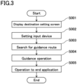
FIG. 3 is a flowchart showing the processing performed by a microcomputer of a smartphone when a car navigation application is executed. -
FIG. 4 is a view showing an image displayed on a touch panel of the smartphone during a guidance operation. -
FIG. 5 is a flowchart showing an operation of a stationary state executed by the display light emitting device according to the first embodiment of the present invention. -
FIG. 6 is a view showing, in time series, when each of the display contents of a guidance image outputted by an image output portion of the display light emitting device is displayed until a guidance point is reached. -
FIG. 7 is a view showing an example of the guidance image outputted by the image output portion of the display light emitting device according to the first embodiment of the present invention. -
FIG. 8 is a view showing an example of the guidance image outputted by the image output portion of the display light emitting device according to the first embodiment of the present invention. -
FIG. 9 is a view showing an example of the guidance image outputted by the image output portion of the display light emitting device according to the first embodiment of the present invention. -
FIG. 10 is a view showing an example of the guidance image outputted by the image output portion of the display light emitting device according to the first embodiment of the present invention. -
FIG. 11 is a view showing a guidance image outputted by the image output portion of a display light emitting device according to a second embodiment of the present invention. -
FIG. 12 is a view showing a guidance image outputted by the image output portion of a display light emitting device according to a third embodiment of the present invention. - Hereinafter, a first embodiment of the present invention will be described based on the drawings.
-
FIG. 1 is a view showing the structure of a navigation system which is an example where the present invention is applied to a motorcycle.FIG. 2 is a functional block diagram showing the structure of the navigation system provided with a display light emitting device according to the first embodiment of the present invention. As shown inFIG. 1 , thisnavigation system 1 is provided with asmartphone 10 as a communication device and ahelmet 20 of the motorcycle. Thenavigation system 1 is also employable for vehicles other than motorcycles such as jet skis, bicycles and snowmobiles (snow bikes). Thesmartphone 10 may be detachably attached to the motorcycle or may be accommodated in a bag or the like capable of receiving GPS signals. - As shown in
FIG. 2 , thesmartphone 10 is provided with: aLAN interface 11 that performs wireless communications using Bluetooth (trademark); aGPS receiver 12; aWAN interface 13 that transmits and receives audio signals through a mobile-phone line; amicrocomputer 14 as a signal processor; and atouch panel 15 as an input portion. Themicrocomputer 14 is provided with: amobile operating system 14a as the OS of thesmartphone 10; a car navigation service application (hereinafter, referred to as "car navigation application") 14b that runs on themobile operating system 14a by using location information obtained by theGPS receiver 12 and the like. Thesmartphone 10 is structured so as to be capable of automatically searching for a route from the current location to the destination based on the location information (current location information) obtained by theGPS receiver 12 and the destination information inputted on thetouch panel 15 and making route setting by using themicrocomputer 14. Thecar navigation application 14b is structured so as to calculate the distance from the current location to the next guidance point and the time to when the next guidance point is reached from the current location, based on map information and current location information. On thetouch panel 15, guidance information up to a predetermined guidance point is displayed. Although concrete examples of the guidance information display will be described later in detail, for example, distance information indicative of the distance to the guidance point and direction information indicative of the direction of travel at the guidance point are displayed. - As shown in
FIG. 1 , in the center on the front surface of thehelmet 20, awindow hole 21 is formed that has a substantially rectangular shape extending in the horizontal direction. Thehelmet 20 is provided with ashield 22 having translucency and being substantially U-shaped in plan view. Both end portions of thewindow hole 21 are pivotally supported by the side wall portions of thehelmet 20, respectively, and move rotationally in the vertical direction, thereby opening and closing thewindow hole 21. A plurality of switches including afirst switch 23 and asecond switch 24 are disposed on the left side of thewindow hole 21 on the outer surface of thehelmet 20 when viewed from the helmet wearer, that is, in a position corresponding to an ear of the helmet wearer. Thefirst switch 23 activates a display light emitting device 30 (described later) of a head-updisplay device 40 by being long-pressed. Thefirst switch 23 forcibly stops the displaylight emitting device 30 by being short-pressed. Thesecond switch 24 is a switch of multiple functions including telephone incoming and telephone conversation. - Moreover, a position to the right of the center in the horizontal direction when viewed from the helmet wearer on the upper edge of the
window hole 21 of thehelmet 20, a plate-likesemi-transparent combiner 26 is attached from the inside of thehelmet 20 through anattachment member 27. The displaylight emitting device 30 according to the embodiment of the present invention and amirror 28 that projects to thecombiner 26 the display light emitted by the displaylight emitting device 30 are incorporated below thewindow hole 21 of thehelmet 20. The displaylight emitting device 30, thecombiner 26 and themirror 28 constitute the head-updisplay device 40. - As shown in
FIG. 2 , the displaylight emitting device 30 is provided with: a Bluetooth module 31 (wireless communication portion) capable of communicating with thesmartphone 10 by using Bluetooth; and animage control module 32 that generates a guidance image to be displayed on thecombiner 26 based on the information received by theBluetooth module 31 and emits display light to display the generated guidance image on thecombiner 26. - The
Bluetooth module 31 receives, from theLAN interface 11 of thesmartphone 10, guidance information such as information on the route to a set guidance point, distance information indicative of the distance to the set guidance point, direction information indicative of the direction of travel at the guidance point, speed information indicative of the current speed and the time required to reach the guidance point. - The
image control module 32 is provided with: amicrocomputer 32a that receives, from theBluetooth module 31, the guidance information received from theLAN interface 11 and generates aguidance image 33 from the received guidance information; a flash ROM (Read Only Memory) 32b that stores images and the like; a GDC (Graphic Display Controller) 32c (image generating portion); and an LCOS (Liquid Crystal on Silicon) 32d (image emitting portion) that emits display light to display the generated image on thecombiner 26. - In accordance with an instruction from the
microcomputer 32a, theimage control module 32 controls theGDC 32c so as to generate theguidance image 33 by combining the guidance information such as the distance information and the direction information received from theBluetooth module 31, images stored in theflash ROM 32b and the like, and controls theLCOS 32d so as to emit display light corresponding to the generatedguidance image 33. In theguidance image 33, for example, as shown inFIG. 7 , adistance image 33a on the distance to the guidance point is displayed by a numerical value in the upper right part, and adirection image 33b indicative of the direction of travel at the guidance point is displayed by an arrow in the upper left part. Moreover, in theguidance image 33, atime image 33c indicative of the time required to reach the guidance point is displayed by minutes and seconds in the lower right part, and a time-of-day image 33d as an estimated arrival time is displayed by a clock diagram in the lower left part. Thedistance image 33a is displayed in the unit of "km" when the distance to the guidance point is long, and is displayed in the unit of "m" when the distance to the guidance point is less than 1 km. - The
LCOS 32d emits display light to display theguidance image 33 generated by theGDC 32c on thecombiner 26. The output of theguidance image 33 by theLCOS 32d can be forcibly stopped by thefirst switch 23 being short-pressed. - In the
navigation system 1 structured as described above, the processing shown in the flowchart ofFIG. 3 is performed by themicrocomputer 14 of thesmartphone 10 executing thecar navigation application 14b. - First, at step S001, a screen to prompt the user to set a destination is displayed on the
touch panel 15. - Then, at step S002, when an input operation to set a destination by the user is performed on the
touch panel 15, the set destination is stored as the destination of the guidance object. - Then, at step S003, the guidance route from the point of departure to the destination of the guidance object stored at step S002 is searched for, and the guidance route obtained by the search is stored.
- Thereafter, at step S004, a guidance operation is executed in accordance with the guidance route stored at step S003. The
microcomputer 14 during the guidance operation obtains, every second, the distance information indicative of the distance to a predetermined guidance point such as the next intersection and the direction information indicative of the direction of travel at the guidance point according to the guidance route obtained by the search using theGPS receiver 12. Then, based on the obtained distance information and direction information, the map around the current location, the distance to the guidance point, the direction of travel at the guidance point and the like are outputted and displayed on thetouch panel 15 as the guidance information.FIG. 4 shows an example of the image displayed on thetouch panel 15 during the guidance operation. InFIG. 4 , 16a is an activation switch of the smartphone, 16b is the map around the current location, 16c is the distance to the guidance point, and 16d is the direction of travel at the guidance point. Moreover, during the guidance operation, themicrocomputer 14 transmits (outputs) the distance information and the direction information obtained by the execution of thecar navigation application 14b, as the guidance information by wireless communication through theLAN interface 11. - During the guidance operation, at step S005, when an input operation to end the
car navigation application 14b by the user is performed on thesmartphone 10, themicrocomputer 14 ends the guidance operation. - Hereinafter, an operation of the
navigation system 1 structured as described above will be described based onFIGS. 5 to 10 . In the following, a case where thenavigation system 1 is activated at a location where a motorcycle is not less the 5 km away will be described as an example. - First, when the driver of a motorcycle or the like wears the
helmet 20 and long-presses thefirst switch 23 while carrying thesmartphone 10 where thecar navigation application 14b is running, the displaylight emitting device 30 is activated. Thesmartphone 10 where thecar navigation application 14b is running transmits the distance information and the direction information updated every second, by wireless communication by theLAN interface 11 as the guidance information up to the guidance point such as the next intersection. After activated, the displaylight emitting device 30 repetitively executes a stationary operation while the wireless communication with thesmartphone 10 is connected by theBluetooth module 31. - In the stationary operation, it is determined whether the motorcycle that the driver is driving reaches a predetermined turning point value (fifth reference distance KY5) or not, and when the motorcycle reaches the predetermined turning point value, the
guidance image 33 is displayed to notify the driver that the guidance route is correct and that the motorcycle is gradually approaching the guidance point. Specifically, when the distance D from the current location to the guidance point is more than 5 km, it is determined that the motorcycle is considerably away from the guidance point and the display of theguidance image 33 of the stationary operation is omitted, whereas when the motorcycle reaches the turning point value, that is, 5 km, theguidance image 33 is displayed for a short period of time (for example, 10 seconds). Then, after theguidance image 33 is displayed for 10 seconds, the display of theguidance image 33 is stopped. As theguidance image 33, for example as shown inFIG. 7 , the direction of travel, the distance to the guidance point, the estimated time of arrival and the like are displayed. Such short-time display of theguidance image 33 is repeated also when the motorcycle reaches other turning point values (fifth reference distances KY5) 4 km, 3 km, 2 km and 1 km. This display enables the driver to recognize that the guidance route is correct and that the motorcycle reaches the turning point value of a predetermined distance and is gradually approaching the guidance point. For example, when running at an average speed of 36 km per hour in an urban area, the motorcycle travels 100 m for ten seconds, and when the motorcycle reaches a turning point value such as 5 km, theguidance image 33 is displayed only while the motorcycle is running a distance of 100 m. Moreover, for example, in a case where an interchange is the guidance point when the motorcycle is running on an express way, the motorcycle travels 200 m for ten seconds when running at an average speed of 72 km per hour, and when the motorcycle reaches a turning point value such as 5 km, theguidance image 33 is displayed while the motorcycle is running a succeeding distance of 200 m. Then, for example, when the location of a first reference distance KY1 as the turning point value where the distance to the guidance point is 500 m is reached, theguidance image 33 is displayed all the time to provide stationary display that makes the driver recognize that the guidance point is approaching and that can surely guide the driver to the guidance point. - This stationary operation will be described in detail based on the flowchart of
FIG. 5 . - First, by the
first switch 23 being long-pressed, the displaylight emitting device 30 of the head-updisplay device 40 is activated, and the process proceeds to step S101. At this step S101, a count value k is initialized to 1 by themicrocomputer 32a of theimage control module 32, and the process proceeds to step S102. The count value is set merely for the sake of convenience. - Then, at step S102, the
Bluetooth module 31 receives the distance information updated and transmitted every second from thesmartphone 10 where thecar navigation application 14b is running, and the process proceeds to step S103. - At step S103, the
microcomputer 32a of theimage control module 32 determines whether a distance condition that a distance D indicated by the distance information received by the Bluetooth module 31 (the distance to the guidance point) is less than a predetermined reference distance Rk is satisfied or not. Here, the count value k starts with k=1 when this displaylight emitting device 30 is activated, and successively becomes k+1, and as the count value k becomes k=1, 2, 3, 4, 5 and 6, Rk successively becomes R1 to R6. In the first embodiment of the present invention, R1 to R6 are set as follows: R1=5 km, R2=4 km, R3=3 km, R4=2 km, R5=1 km, and R6=500 m. - When the result of the determination is NO at S103, since it is a case where the distance condition that the distance from the current location to the guidance point is less than the reference distance Rk is not satisfied, the process proceeds to step S104. That is, since the count value k=1 at first and Rk=R1=5 km, it is determined whether the distance D is D≤5 km (fifth reference distance KY5) or not. Since the current location of travel (D>5 km) is not less than 5 km away from the guidance point and the distance condition (D≤5 km) is not satisfied, the process proceeds to step S104 where the next reception is waited for and the display of the
guidance image 33 of the stationary operation is not executed. - At step S104, since the current location of travel is not less than 5 km away from the guidance point, the display of the
guidance image 33 of the stationary operation is omitted, and the process waits until the distance information and the direction information transmitted by thesmartphone 10 are newly received by theBluetooth module 31 and returns to step S102. That is, since the distance D during traveling is not less than 5 km, the process proceeds from step S104 to S102 and the determination at step S103 is repeated until the distance information updated every second becomes not more than 5 km. - On the other hand, when the location of travel updated every second becomes D≤5 km, since the distance condition is satisfied, the determination result is YES at step S103, and the process proceeds to step S105. At step S105, the
microcomputer 32a determines whether the count value k is 6 or not. When the count value k is not 6, the determination result is NO, and the process proceeds to step S106. On the other hand, when the count value k is 6, the determination result is YES, and the process proceeds to step S109. That is, k=6 is D6=500 m, and it is determined whether or not the location of the distance D is not more than 500 m (first reference distance KY1) which is a distance near the guidance point. When it is not more than 500 m, the determination result is YES, and the process proceeds to step S109 where determining that a distance near the guidance point is reached, the display of theguidance image 33 is performed. On the other hand, when the location of the distance D is not less than 500 mm away from the guidance point, the determination result is NO, and the process proceeds to step S106 where anotherguidance image 33 indicating that a distance near the guidance point is not reached is displayed. - At step S106, the
microcomputer 32a determines whether the distance D≤Rk+1 is satisfied or not. When the distance D≤Rk+1 is not satisfied, the determination result is NO, and the process proceeds to step S107. On the other hand, when it is satisfied, the determination result is YES, and the process proceeds to step S108. That is, in the above-described case, since the count value k=1, Rk+1=R2=4 km, and it is determined whether the distance D to the guidance point satisfies the distance condition that D≤4 km (fifth reference distance KY5) or not. Although D<5 km at the location of travel at this time and the distance is updated every second, since themicrocomputer 32a makes the determination within a short period of time of several microseconds, it can be said that the distance D at the current location of travel is between 5 km and 4 km. Therefore, since the distance D≤R2 (4 km) is not satisfied, the determination result is NO, and the process proceeds to step S107. - At step S107, the
LCOS 32d continues to emit display light to display theguidance image 33 on thecombiner 26 for ten seconds. In theguidance image 33, as shown inFIGS. 6 and7 , the numerical value of thedistance image 33a, the arrow of thedirection image 33b of the direction of travel, thetime image 33c (time required to arrive) and the time-of-day image 33d (estimated time of arrival) are displayed. The value of 5 km as thedistance image 33a, the right-turn arrow as thedirection image 33b, six minutes as the required time of thetime image 33c and ten o'clock as the estimated time of arrival of the time-of-day image 33d shown inFIG. 7 are merely samples and are not the actual numerical values and required time. Moreover, as shown inFIG. 6 , an announcement "About 5 km ahead, in the direction of ...." is provided by voice guidance. At this location of travel, since the distance D to the guidance point is not not more than 500 m and it is unnecessary to display theguidance image 33 all the time, theguidance image 33 is displayed only for a short period of time. While thisguidance image 33 is displayed, theGDC 32c of theimage control module 32 generates theguidance image 33 by combining with the information of theflash ROM 32b in accordance with an instruction from themicrocomputer 32a, and theLCOS 32d emits display light to display theguidance image 33 generated by theGDC 32c on thecombiner 26. Since the distance received by theBluetooth module 31 is updated every second, the numerical value of thedistance image 33a of the generatedguidance image 33 is also updated every second. Moreover, not only the numerical value of thedistance image 33a of theguidance image 33 but also the display of thetime image 33c and the display of the clock diagram of the time-of-day image 33d are also updated every second. Then, when ten seconds have elapsed since the start of the display light emission by theLCOS 32d, the display light emission by theLCOS 32d is ended, and the process proceeds to step S108. - At step S108, after the
microcomputer 32a adds 1 to the count value k to make the count value k=2, the process returns to step S102. - Then, at step S102, a new distance D is received. Thereafter, whether or not the new distance D obtained at step S102 is not more than R2, that is, not more than R2=4 km (fifth reference distance KY5) is determined at step S103. Under a condition where it is not not more than 4 km, the determination result is NO, and the process is returned to S102 without the emission of the display light. Under this condition, since display light is not emitted, the
guidance image 33 is not displayed, either. Since the distance D at the current location of travel is between 5 km and 4 km and the distance D is updated every second, the motorcycle runs without theguidance image 33 displayed until the display condition of theguidance image 33 is satisfied. - Then, when the distance D updated every second becomes D≤4 km, since it is determined at step S103 that the distance D is not more than 4 km, the process proceeds to step S107 through steps S105 and step S106, and the
guidance image 33 in accordance with the distance at that time is displayed for ten seconds. Thereafter, the process proceeds to step S108, the count value becomes k=3, and the process returns to step S102. - In this manner, short-time display of the
guidance image 33 as described above is repeated when Rk becomes R3, R4 and R5. That is, when Rk becomes R3=3 km (fifth reference distance KY5), R4=2 km (fifth reference distance KY5) and R5=1 km, for example, theguidance image 33 as shown inFIG. 6 is displayed for ten seconds. When the process proceeds to step S108 after theguidance image 33 is displayed for ten seconds every time the location where R5=1 km is passed, k=k+1, that is, k=6 and Rk=R6=500 m. Then, the process returns to step S102. - Thereafter, the process proceeds from step S102 to step S103, and it is determined whether or not the distance D to the guidance point is not more than 500 m (first reference distance KY1) that is a distance near the guidance point. When the distance D becomes not more than 500 m, since the determination result is YES and D≤Rk (Rk=R6=500 m) is satisfied at step S103, the process proceeds to step S105. At step S205, whether k=6 or not is determined. Since k=6 under this running condition, the determination result is YES, and the process proceeds to step S109.
- At step S109, display as a distance near the guidance point is provided. That is, the process proceeds to step S109 and display light to display the
guidance image 33 on thecombiner 26 continues to be emitted until D=0 km (guidance point). At this time, theGDC 32c generates theguidance image 33 in accordance with an instruction from themicrocomputer 32a, and theLCOS 32d emits display light to display theguidance image 33 generated by theGDC 32c on thecombiner 26. Specifically, as shown inFIGS. 6 and7 , in theguidance image 33, thedistance image 33a to the guidance point is displayed by a black numerical value on the right side in the upper row, and thedirection image 33b at the guidance point is displayed by a blue arrow on the left side in the upper row. The display image of thisdirection image 33b will be referred to as first route direction image 33b1. Moreover, in theguidance image 33, thetime image 33c as the time required to reach the guidance point is displayed by black numerical value on the right side in the lower row, and the clock diagram of the time-of-day image 33d as the estimated time of arrival is displayed in black on the left side in the lower row. Theguidance image 33 when the first reference distance KY1 is reached is the same as theguidance image 33 displayed for ten seconds when each fifth reference distance KY5 is reached, and is different in that it is displayed all the time. Moreover, since the distance received by theBluetooth module 31 is updated every second, the generatedguidance image 33 is also updated every second. That is, the numerical value of thedistance image 33a is updated every second. Then, the process proceeds to step S110. - At step S110, it is determined whether the distance D indicated by the distance information received by the
Bluetooth module 31 is not more than 200 mm (third reference distance KY3) or not. When the distance D is not not more than 200 m at step S109, the determination result is NO, and the process returns to step S109. On the other hand, when the distance D becomes not more than 200 mm, the determination result is YES, and the process proceeds to step S111. - At step S111, as shown in
FIGS. 6 and8 , the first route direction image 33b1 which is the display image of the blue arrow of theguidance image 33 is changed to a second route direction image 33b2 which is the display image of a yellow arrow, thereby inviting the driver's attention in the direction of travel, and the process proceeds to step S112. - At step S112, it is determined whether the distance D indicated by the distance information received by the
Bluetooth module 31 is not more than 150 m (second reference distance KY2) or not. When the distance D is not not more than 150 m at step S112, the determination result is NO, and the process returns to step S111. On the other hand, when the distance D becomes not more than 150 m, the determination result is YES, and the process proceeds to step S113. - At step S113, as shown in
FIGS. 6 and9 , the numerical display of thedistance image 33a of theguidance image 33 is erased so as not to be displayed. By doing this, the driver is made to recognize that it is hardly worth displaying the distance in theguidance image 33 because the distance D to the guidance point is considerably near, and the display of the direction of travel in theguidance image 33 is made conspicuous; thereafter, the process proceeds to step S114. While thetime image 33c and the time-of-day image 33d in theguidance image 33 are displayed as they are in theguidance image 33 at this time, these displays may also be erased. - At step S114, it is determined whether the distance D indicated by the distance information received by the
Bluetooth module 31 is not more than 70 m (fourth reference distance KY4) or not. When the distance D is not not more than 70 m at step S114, the determination result is NO, and the process returns to step S113. On the other hand, when the distance D becomes not more than 70 m, the determination result is YES, and the process proceeds to step S115. - At step S115, as shown in
FIGS. 6 and10 , under a condition where the numerical display of thedistance image 33a in theguidance image 33 is erased, the display image of the yellow arrow of the second route direction image 33b2 is changed to a third route direction image 33b3 formed of a display image of a red arrow, thereby further inviting the driver's attention to the direction of travel, and the process proceeds to step S116. While thetime image 33c and the time-of-day image 33d in theguidance image 33 are displayed as they are in theguidance image 33 at this time, these displays may also be erased. - At step S116, it is determined whether the distance D indicated by the distance information received by the
Bluetooth module 31 is 0 m or not. When the distance D is not 0 m at step S116, the determination result is NO, and the process returns to step S115. On the other hand, when the distance D becomes 0 m, the determination result is YES, and all the display light emitted from theLCOS 32d is turned off and the display of theguidance image 33 in the stationary condition is ended. After the end of these stationary operations, the guidance point is switched, and the next stationary operations are continuously performed. - As described above, according to the first embodiment, when the distance D to the guidance point becomes near the guidance point, the display color of the travel direction of the
direction image 33b is successively changed, for example, from blue to yellow and from yellow to red so as to be conspicuous, so that the driver's attention is attracted more to the direction of travel than to the distance information. When the location at a distance near the guidance point is reached, the display of thedistance image 33a is stopped and the display of thedirection image 33b is continued, so that not only the driver can strongly recognize that the guidance point is approaching but also thedistance image 33a can be prevented from obstructing a correct judgement by the driver. - In particular, in the first embodiment, since the display image color of the arrow of 200 m (third reference distance KY3) is changed from blue to yellow and the distance display is stopped at the point of 150 m (second reference distance KY2) after this color change, the driver's attention is more strongly focused on the direction of travel. Thereafter, since the display image color of the arrow of the
direction image 33b is changed from yellow to red at the point of 70 m (fourth reference distance KY4), the driver's attention is further focused on the direction of travel, so that the motorcycle can travel according to the guidance without mistaking a wrong direction for the direction of travel at the guidance point. In particular, since the navigation system is such that the numerical value itself of the distance is indicated by a rough numerical value in units of several hundreds of meters, if thedistance image 33a is displayed adhering to numerical values of short distances, there is a possibility that the motorcycle runs with the distance to the guidance point not coinciding with the distance displayed in thedistance image 33a. Therefore, in the first embodiment, by daring to erase the display of the distance numerical value when the distance (150 m=the second reference distance KY2) near the guidance point is reached, the driver can drive with attention focused on thedirection image 33b without adhering to the distance numerical value. - While in the above description of the stationary operation, a case in which the
navigation system 1 is activated at a location where the motorcycle is not less than 5 km away from the guidance point is described as an example, the displaylight emitting device 30 operates according to the flowchart shown inFIG. 5 also when thenavigation system 1 is activated at a location where the motorcycle is less than 5 km away from the guidance point. A case in which thenavigation system 1 is activated, for example, at a location where the motorcycle is 3.4 km away from the guidance point will be described as an example. Regarding steps similar to the above-described ones, brief description will be given. - When the
first switch 23 is long-pressed at a location where the motorcycle is 3.4 km away from the guidance point, the displaylight emitting device 30 of the head-updisplay device 40 is activated, and at step S101, the count value k is initialized to 1 by themicrocomputer 32a. - Then, at step S102, the
Bluetooth module 31 receives the distance information updated and transmitted every second from thesmartphone 10 where thecar navigation application 14b is running, and the process proceeds to step S103. - At step S103, whether a distance condition that the distance D≤R1 (R1=5 km) is satisfied or not is determined. Since D=3.4 km, determining that the display condition is satisfied, the process proceeds to step S105.
- At step S105, whether the count value k is k=6 or not is determined. Since the count value k is k=1, the process proceeds to step S106.
- At step S106, whether the distance D≤Rk+1 (Rk+1=R2=4 km) is satisfied or not is determined. Since the distance D=3.4 km and D≤4 km is satisfied, the process proceeds to step S108.
- At step S108, after the
microcomputer 32a adds 1 to the count value k to thereby make the count value k=2, the process returns to S102. - Then, when a new distance D is received at step S102, whether the distance D is not more than R2, that is, not more than Rk=R2=4 km or not is determined at step S103. Since the current point is a location where D=3.4 km, determining that the determination condition is satisfied, the process proceeds to step S105.
- At step S105, whether the count value k is k=6 or not is determined. At this time, since the count value k is k=2 and not k=6, determining that the determination condition is not satisfied, the process proceeds to step S106.
- At step S106, whether D≤Rk+1 is satisfied or not is determined. Since Rk+1=R3=3 km and the current distance D is D=3.4 km, the determination condition D(3.4 km)≤R3(3 km) is not satisfied. Therefore, the process proceeds to step S107. The steps above are executed in several milliseconds.
- At step S107, a
guidance image 33 at a location where the current point is D=3.4 km is generated by theimage control module 32, and display light of theguidance image 33 is emitted by theLCOS 32d and displayed on thecombiner 26 for ten seconds. Then, after ten seconds have elapsed since the start of the display light emission, theLCOS 32d ends the display light emission, and the process proceeds to step S108. - At step S108, the count value k is made k=3, and the process returns to step S102. In this way, when Rk successively becomes R3, R4 and R5 and the current point becomes 3 km, 2 km and 1 km, the ten-second display of each
guidance image 33 is performed. Then, when Rk becomes R6 and the current point becomes alocation 500 m away from the guidance point, the all-time display of theguidance image 33 is performed. - As described above, when the current location is at a point 3.4 km away from the guidance point, the operation is executed until the count value k becomes from k=1 to k=2 according to the flow chart shown in
FIG. 5 to identify the current location, the ten-second display of theguidance image 33 is executed at this point, and thereafter, the ten-second display of theguidance image 33 is repeated at the points of 3 km, 2km and 1 km. Thereafter, when Rk becomes R6 and the current location is alocation 500 m away from the guidance point, the all-time display of theguidance image 33 is executed. - Moreover, when the
first switch 23 is long-pressed at a location where the motorcycle is 0.4 km away from the guidance point, the displaylight emitting device 30 of the head-updisplay device 40 is activated. After the count value k is initialized to 1 at step S101, steps as described above are repeated until the count value k successively becomes from k=1 to k=6. When k=6 after the determination is made at step S105, the process proceeds to step S109, and the above-described display operation for when the guidance point is approaching is executed. That is, the display of theguidance image 33 at a location near the guidance point is executed without the ten-second display of theguidance image 33 being executed. - As described above, in the flowchart shown in
FIG. 5 , in a case where thenavigation system 1 is activated and the stationary operation is performed, for example, when thenavigation system 1 is actuated at a location not less than 5 km away from the guidance point, theguidance image 33 is displayed for ten seconds atlocations 5 km, 4 km, 3 km, 2 km and 1 km away from the guidance point, and the location not more than 500 m away from the guidance point is reached, theguidance image 33 is displayed all the time. Moreover, when thenavigation system 1 is activated at a location nearer to the guidance point than thelocation 5 km away from the guidance point, since whether the current location is between Rk and Rk+1 or the count value k=6 or not is immediately determined, the current location can be instantaneously grasped and the necessary steps can be executed. That is, when thenavigation system 1 is activated, by executing the flow to successively increase the count value k by one from 1, the current location of the driver can be instantaneously identified and the necessary steps can be executed at any location. - In particular, when the distance to the guidance point becomes a near distance of not more than 500 mm (first reference distance KY1), the
guidance image 33 is displayed all the time to provide guidance, and at a location extremely near the guidance point (second reference distance KY2), for example, at alocation 150 m away from the guidance point, the display of thedistance image 33a of theguidance image 33 is stopped and guidance is provided only by thedirection image 33b, so that the driver can drive on a correct route according to the direction information without influenced by the distance information at a location extremely near the guidance point. - In common navigation systems, since the guidance point of the vehicle is measured and displayed by a rough value of approximately several hundreds of meters, the numerical value of the distance can be incorrect at an extremely near location within several hundreds of meters from the guidance point. On the contrary, according to the present invention, since the
distance image 33a as the distance information is erased when a location extremely near the guidance point is reached as described above, the driver is never misled by thedistance image 33a when guided to the guidance point by theguidance image 33. In that case, since the driver's attention is further paid on thedirection image 33b by changing the display condition of thedirection image 33b so as to be conspicuous, the driver's attention to thedirection image 33b increases, so that the driver can surely drive to the guidance point according to the direction information. - It is preferable that the second reference distance as the distance to a location extremely near the guidance point be approximately 100 to 200 m.
- A second embodiment will be described based on
FIG. 11 . The second embodiment is different from the first embodiment in that the distance information of theguidance image 33 shown when the driver reaches the fourth reference distance (70 m) is changed, and is the same as the first embodiment except for this. - That is, as shown in
FIG. 11 , thedirection image 33b of theguidance image 33 is displayed in a similar manner to thedirection image 33b of the first embodiment, and an easy-to-understand display is provided by acharacter image 33e "Turn right at the next traffic light, in the direction of ..." indicating the direction of travel at the guidance point by characters. At this time, the time image is erased together with the distance information. - In this second embodiment, since information on the intersection at the guidance point is displayed in the
guidance image 33 in detail and in an easy-to-understand manner, the driver can be made less likely to make a mistake in the direction of travel at the guidance point. - A third embodiment will be described based on
FIG. 12 . The third embodiment is different from the first embodiment in that theguidance image 33 displayed when the driver reaches the fourth reference distance (70 m) is changed, and is the same as the first embodiment except for this. - That is, in the third embodiment, for example, as shown in
FIG. 12 , a phrase "in the direction of ..." which is an explanation by voice is displayed also by acharacter image 33f as it is in theguidance image 33 so as to be easy-to-understand. Further, in the lower row of theguidance image 33, the arrow of adirection image 33g and the numerical value of adistance image 33h at the guidance point next to the currently explained guidance point are displayed next to each other. By adding these pieces of information at the next guidance point to theguidance image 33, the information on the next guidance point becomes clear, so that the driver can drive at ease. In particular, how much distance there is to the next guidance point or in which direction the next guidance point is can be easily understand, so that the driver can drive without making a mistake in the direction of travel. As described above, in a case where the next guidance point is near the currently explained guidance point and information on the next guidance point is immediately required, for example, during driving in a labyrinthine urban area, when the intersection as the guidance point explained next to the currently explained guidance point is located at a near distance such as 50 m or 100 m from the currently explained guidance point, the driver can drive without making a mistake in the direction of travel. - Moreover, in the above-described first to third embodiments, the
LCOS 32d may emit display light in such a manner that theguidance image 33 is faded in when the display of theguidance image 33 by the stationary operation is started and that the guidance image is faded out when the display of the guidance image by the stationary operation is ended. By doing this, when the display of theguidance image 33 is started, theguidance image 33 displayed on thecombiner 26 gradually increases in brightness, whereas when the display of theguidance image 33 is ended, theguidance image 33 displayed on thecombiner 26 gradually decreases in brightness, so that strain on the eyes of the driver wearing thehelmet 20 can be reduced. - Moreover, while in the above-described first to third embodiments, the color of the arrow is changed from blue to yellow and from yellow to red as an example of the change of the display image of the
direction image 33b, the present invention is not limited to these colors but different colors may be used. Moreover, the change display of thedirection image 33b is only necessarily a display that is conspicuous to such an extent not as to be an obstruction during traveling; for example, the flashing condition of the arrow, the thickness and size of the arrow, a combination thereof and the like may be changed for display. - Moreover, while in the above-described first to third embodiments, the first reference distance is set to 500 m, the third reference distance, to 200 m, the second reference distance, to 150 m and the fourth reference distance, to 70, these numerical values are examples and different numerical values may be used.
- Moreover, the above-mentioned numerical values may be changed according to the speed of the vehicle. The above-mentioned numerical values may be changed according to the congestion condition, the number of driving lanes, the road width and the like. Moreover, the above-mentioned numerical values may be changed according to an intersection, an express way, an interchange or the like.
- Although it is more noticeable to the driver's eyes that the positions where the color of the arrow of the
direction image 33b is changed, that is, the position of 200 m of the third reference distance and the position of 70 m of the fourth reference distance are different from the position where the display of thedistance image 33a disappears, that is, the position of 150 m of the second reference distance, the positions may be the same. - While the numerical values of the first reference distance, the second reference distance, the third reference distance, the fourth reference distance and the fifth reference distance are automatically set, they may be changed manually.
- The numerical values of the first reference distance, the second reference distance, the third reference distance, the fourth reference distance and the fifth reference distance, that is, 500 m, 1 km, 2km, 3 km, 4 km and 5 km are examples, and the present invention is not limited to these numerical values; they may be 3 km, 2 km, 1 km, 500 m or may be 3 km, 2.5 km, 2 km, 1.5 km, 1 km, 500 m and 300 m.
- In particular, at a location farther from the guidance point than the location at the first reference distance (500 m) from the guidance point, display is executed every predetermined distance (1 km) longer than the first reference distance, whereas when the first reference distance is shorter than 1 km, a different numerical value may be used.
- While the
guidance image 33 when the driver is at alocation 500 m away from the guidance point and theguidance images 33 when the driver is atlocations 5 km, 4 km, 3 km, 2 km and 1 km are of the same kind,different guidance images 33 may be displayed at the locations. - While in the first to third embodiments, ten seconds are shown as an example of the short time during which the
guidance image 33 is displayed at the location of the fifth reference distance, this numerical value is merely an example and the present invention is not limited to this numerical value. That is, since it is necessary only that the driver can quickly recognize that the landmark distance is reached while driving and if the driver can recognize it, it is preferable to quickly erase the display to increase the field of view, the display time may be shorter than ten seconds. On the contrary, since the driver is hindered from making a correct judgement if the display time is too long, it is preferable that the display time be not more than 30 seconds at the longest. - When the
navigation system 1 is activated at a location not less than 5 km away from the guidance point, although no stationary operation is performed for theguidance image 33, a different guidance image may be displayed, or voice information may be provided. For example, a voice such that "The guidance point is not less than 5 km away. Please continue driving along the traveling road." may be outputted. - The present invention is usable as a display light emitting device that emits display light to display a guidance image on a combiner mounted on a helmet.
-
- 1
- Navigation system
- 10
- Communication device smartphone
- 20
- Helmet
- 26
- Combiner
- 30
- Display light emitting device
- 31
- Bluetooth module (wireless communication portion)
- 32
- Image control module
- 32s
- Microcomputer
- 32b
- Flash ROM
- 32c
- GDC (image generating portion)
- 32d
- LCOS (image emitting portion)
- 33
- Guidance image
- 33a
- Distance image
- 33b
- Direction image
- 33b1
- First route direction image
- 33b2
- Second route direction image
- 33b3
- Third route direction image
- 33c
- Time image
- 33d
- Time-of-day image
- 40
- Head-up display device
- KY1
- First reference distance
- KY2
- Second reference distance
- KY3
- Third reference distance
- KY4
- Fourth reference distance
- KY5
- Fifth reference distance
Claims (8)
- A display light emitting device (30) that emits display light to display a guidance image (33) on a combiner (26) mounted on a helmet (20), comprising;a wireless communication portion configured to receive, from a communication device, guidance information including distance information indicative of a distance from a current location to a predetermined guidance point and direction information indicative of a direction of travel at the guidance point; andan image control module (32) having: an image generating portion configured to generate a guidance image (33) including a distance image (33a) indicative of the distance to the guidance point based on the distance information and a direction image (33b) indicative of the direction of travel at the guidance point based on the direction information; and an image emitting portion configured to emit display light to display the guidance image (33) on the combiner (26), and configured to control operations of the image generating portion and the image emitting portion,wherein the image control module (32) is configured to perform control so that, when a condition is satisfied that the distance indicated by the distance information is less than a predetermined first reference distance (KY1), the distance image (33a) and the direction image (33b) are generated by the image generating portion and display light to display the guidance image (33) including the generated distance image (33a) and direction image (33b) on the combiner (26) is emitted from the image emitting portion, andperform control so that from when a condition is satisfied that the distance indicated by the distance information is less than a second reference distance (KY2) shorter than the first reference distance (KY1) to when the guidance point is reached, the display of the distance image (33a) of the guidance image (33) is stopped and display light to continue to display the direction image (33b) is emitted,wherein a fifth reference distance (KY5) is set that is from the guidance point to a location further away from the guidance point than the location of the first reference distance (KY1),the fifth reference distance (KY5) is set at a plurality of points every distance interval longer than the first reference distance (KY1), andthe image control module (32) is configured to perform control so that the guidance image (33) including the distance image (33a) and the direction image (33b) is displayed for a set predetermined period of time when each fifth reference distance (KY5) is reached and, after the predetermined period of time, a display condition before the guidance image (33) including the distance image (33a) and the direction image (33b) is displayed returns.
- The display light emitting device according to claim 1,wherein the image control module (32) is configured to perform control so that until a third reference distance (KY3) shorter than the first reference distance (KY1) is reached, the direction image (33b) generated by the image generating portion is a first route direction image (33b1), andthat when a condition is satisfied that the distance indicated by the distance information is less than the third reference distance (KY3), the direction image (33b) generated by the image generating portion continues to be emitted from the image emitting portion to the combiner (26) as a second route direction image (33b2) formed of a display image different from the first route direction image (33b1).
- The display light emitting device according to claim 2,
wherein the image control module (32) is configured to perform control so that when a condition is satisfied that the distance indicated by the distance information is less than a fourth reference distance (KY4) shorter than the third reference distance (KY3), a third route direction image (33b3) formed of a display image different from the first route direction image (33b1) and the second route direction image (33b2) is emitted from the image emitting portion to the combiner (26). - The display light emitting device according to claim 3,
wherein the second reference distance (KY2) is shorter than the third reference distance (KY3) and is longer than the fourth reference distance. - The display light emitting device according to any one of claims 1 to 4,wherein the first route direction image (33b1) and the second route direction image (33b2) each include an arrow image, andthe arrow image of the first route direction image (33b1) and the arrow image of the second route direction image (33b2) are different in display condition.
- The display light emitting device according to claim 3 or 4,wherein the first route direction image (33b1), the second route direction image (33b2) and the third route direction image (33b3) each include an arrow image, andthe arrow images of the first route direction image (33b1), the second route direction image (33b2) and the third route direction image (33b3) are different in display condition.
- The display light emitting device according to any one of claims 1 to 6,
wherein the distance interval from the location of the second reference distance (KY2) to the guidance point is shorter than the distance interval from the location of the first reference distance (KY1) to the location of the second reference distance (KY2). - The display light emitting device according to claim 1,
wherein the predetermined period of time is not more than 30 seconds.
Applications Claiming Priority (2)
| Application Number | Priority Date | Filing Date | Title |
|---|---|---|---|
| JP2019230324A JP7545205B2 (en) | 2019-12-20 | 2019-12-20 | Display light emitting device |
| PCT/JP2020/037208 WO2021124641A1 (en) | 2019-12-20 | 2020-09-30 | Display light emitting device |
Publications (3)
| Publication Number | Publication Date |
|---|---|
| EP4079553A1 EP4079553A1 (en) | 2022-10-26 |
| EP4079553A4 EP4079553A4 (en) | 2023-01-18 |
| EP4079553B1 true EP4079553B1 (en) | 2025-06-25 |
Family
ID=76477190
Family Applications (1)
| Application Number | Title | Priority Date | Filing Date |
|---|---|---|---|
| EP20903660.7A Active EP4079553B1 (en) | 2019-12-20 | 2020-09-30 | Display light emitting device |
Country Status (5)
| Country | Link |
|---|---|
| US (1) | US12078503B2 (en) |
| EP (1) | EP4079553B1 (en) |
| JP (1) | JP7545205B2 (en) |
| CN (1) | CN114845899B (en) |
| WO (1) | WO2021124641A1 (en) |
Families Citing this family (3)
| Publication number | Priority date | Publication date | Assignee | Title |
|---|---|---|---|---|
| JP7767738B2 (en) * | 2021-06-01 | 2025-11-12 | マツダ株式会社 | Head-up display device |
| CN119317814A (en) * | 2022-05-30 | 2025-01-14 | Tvs电机股份有限公司 | Driver assistance system for vehicle and method thereof |
| US12439994B2 (en) | 2023-03-23 | 2025-10-14 | Honda Motor Co., Ltd. | Helmet system having a rear mount for a cellphone for a saddle riding vehicle |
Family Cites Families (24)
| Publication number | Priority date | Publication date | Assignee | Title |
|---|---|---|---|---|
| JP2578338Y2 (en) | 1991-04-02 | 1998-08-13 | 富士通テン株式会社 | Automobile route guidance device |
| JPH08190696A (en) | 1994-11-07 | 1996-07-23 | Nippondenso Co Ltd | Route guide data display device |
| DE69625309T2 (en) * | 1995-10-04 | 2003-09-18 | Aisin Aw Co., Ltd. | Vehicle navigation device |
| JP3580454B2 (en) | 1995-10-12 | 2004-10-20 | 本田技研工業株式会社 | Navigation system |
| JP3555466B2 (en) | 1998-10-09 | 2004-08-18 | 株式会社エクォス・リサーチ | Navigation center device and navigation device |
| US6249740B1 (en) | 1998-01-21 | 2001-06-19 | Kabushikikaisha Equos Research | Communications navigation system, and navigation base apparatus and vehicle navigation apparatus both used in the navigation system |
| US6466815B1 (en) * | 1999-03-30 | 2002-10-15 | Olympus Optical Co., Ltd. | Navigation apparatus and surgical operation image acquisition/display apparatus using the same |
| DE19944067A1 (en) * | 1999-09-14 | 2001-03-15 | Mannesmann Vdo Ag | Procedure for displaying primary and secondary information |
| JP3861642B2 (en) | 2001-09-17 | 2006-12-20 | アイシン・エィ・ダブリュ株式会社 | Vehicle navigation device |
| JP4767136B2 (en) | 2006-09-07 | 2011-09-07 | 川崎重工業株式会社 | Information disclosure device |
| JP2008232940A (en) | 2007-03-22 | 2008-10-02 | Denso Corp | Information providing device for motorcycles |
| US20130024117A1 (en) * | 2011-07-18 | 2013-01-24 | Pavetti Scott R | User Navigation Guidance and Network System |
| JP5881566B2 (en) | 2012-09-10 | 2016-03-09 | アルパイン株式会社 | Navigation device and navigation information display control method |
| US9146124B2 (en) | 2012-12-18 | 2015-09-29 | Nokia Technologies Oy | Helmet-based navigation notifications |
| JP2014235054A (en) | 2013-05-31 | 2014-12-15 | パイオニア株式会社 | Display device, method, and program |
| JP2015136953A (en) | 2014-01-20 | 2015-07-30 | アルパイン株式会社 | Two-wheeled vehicle information provision device |
| JP6557868B2 (en) * | 2014-03-27 | 2019-08-14 | パナソニックIpマネジメント株式会社 | Virtual image display device, head-up display system, and vehicle |
| WO2016022984A1 (en) * | 2014-08-08 | 2016-02-11 | Fusar Technologies, Inc. | Helmet system and methods |
| JP6627214B2 (en) | 2014-11-10 | 2020-01-08 | 日本精機株式会社 | Information display device, control method, program, and storage medium |
| US9207092B1 (en) * | 2014-12-22 | 2015-12-08 | Google Inc. | Displaying navigation information within a secondary user interface of a mobile device |
| KR102359544B1 (en) * | 2015-06-22 | 2022-02-08 | 엘지전자 주식회사 | Deformable display device and operating method thereof |
| JP6331154B2 (en) | 2016-02-29 | 2018-05-30 | 本田技研工業株式会社 | Vehicle and vehicle control method |
| EP3438805B1 (en) | 2016-03-31 | 2020-09-09 | Honda Motor Co., Ltd. | Image display apparatus and image display method |
| JP2019061559A (en) | 2017-09-27 | 2019-04-18 | 本田技研工業株式会社 | Display device, display control device and vehicle |
-
2019
- 2019-12-20 JP JP2019230324A patent/JP7545205B2/en active Active
-
2020
- 2020-09-30 US US17/785,808 patent/US12078503B2/en active Active
- 2020-09-30 EP EP20903660.7A patent/EP4079553B1/en active Active
- 2020-09-30 CN CN202080088896.7A patent/CN114845899B/en active Active
- 2020-09-30 WO PCT/JP2020/037208 patent/WO2021124641A1/en not_active Ceased
Also Published As
| Publication number | Publication date |
|---|---|
| CN114845899B (en) | 2024-11-12 |
| EP4079553A1 (en) | 2022-10-26 |
| CN114845899A (en) | 2022-08-02 |
| JP7545205B2 (en) | 2024-09-04 |
| JP2021098411A (en) | 2021-07-01 |
| WO2021124641A1 (en) | 2021-06-24 |
| US12078503B2 (en) | 2024-09-03 |
| US20230058898A1 (en) | 2023-02-23 |
| EP4079553A4 (en) | 2023-01-18 |
Similar Documents
| Publication | Publication Date | Title |
|---|---|---|
| EP4079553B1 (en) | Display light emitting device | |
| US20220289228A1 (en) | Hmi control device, hmi control method, and hmi control program product | |
| US20210372810A1 (en) | Display control device, display control method, and non-transitory tangible computer-readable medium therefor | |
| US9302613B2 (en) | Automatic activation of turn signals in a vehicle | |
| EP2485204A1 (en) | Driving support apparatus for vehicle | |
| JP2010127685A (en) | Navigation apparatus | |
| JP4534922B2 (en) | Virtual leading vehicle image display system | |
| WO2011081157A1 (en) | Navigation device and method of searching route by the same | |
| EP3506239A1 (en) | Vehicle on-board communication device and vehicle | |
| CN113196377B (en) | Display light emitting device, head-up display device, image display system, and helmet | |
| WO2020130031A1 (en) | Navigation system | |
| JP2016176962A (en) | Display device, head-up display, control method, program, and storage medium | |
| JP2021047544A (en) | Congestion information providing system | |
| EP4222452B1 (en) | Navigation method, navigation apparatus, color indicating apparatus and transportation guiding apparatus | |
| JP2022031340A (en) | Display devices, head-up displays, control methods, programs and storage media | |
| JP7348038B2 (en) | Display light emitting device | |
| KR20180012652A (en) | Information display system for automobile | |
| JP2006098983A (en) | Display device | |
| US20210302191A1 (en) | Route guiding apparatus | |
| JP2013257269A (en) | Display device, head-up display, control method, program, and storage medium | |
| JP2020064076A (en) | Display device, head-up display, control method, program and storage medium | |
| JP7433025B2 (en) | Display light emitting device | |
| JP2006308570A (en) | Navigation system | |
| JP4596245B2 (en) | Vehicle display device | |
| JP2018159714A (en) | Display device, head-up display, control method, program, and storage medium |
Legal Events
| Date | Code | Title | Description |
|---|---|---|---|
| STAA | Information on the status of an ep patent application or granted ep patent |
Free format text: STATUS: THE INTERNATIONAL PUBLICATION HAS BEEN MADE |
|
| PUAI | Public reference made under article 153(3) epc to a published international application that has entered the european phase |
Free format text: ORIGINAL CODE: 0009012 |
|
| STAA | Information on the status of an ep patent application or granted ep patent |
Free format text: STATUS: REQUEST FOR EXAMINATION WAS MADE |
|
| 17P | Request for examination filed |
Effective date: 20220615 |
|
| AK | Designated contracting states |
Kind code of ref document: A1 Designated state(s): AL AT BE BG CH CY CZ DE DK EE ES FI FR GB GR HR HU IE IS IT LI LT LU LV MC MK MT NL NO PL PT RO RS SE SI SK SM TR |
|
| A4 | Supplementary search report drawn up and despatched |
Effective date: 20221221 |
|
| RIC1 | Information provided on ipc code assigned before grant |
Ipc: A42B 3/04 20060101ALI20221215BHEP Ipc: G06F 3/0481 20220101ALI20221215BHEP Ipc: G06F 3/01 20060101ALI20221215BHEP Ipc: G02B 27/02 20060101ALI20221215BHEP Ipc: H04N 5/74 20060101ALI20221215BHEP Ipc: G01C 21/36 20060101ALI20221215BHEP Ipc: G08G 1/0968 20060101ALI20221215BHEP Ipc: G09G 5/00 20060101ALI20221215BHEP Ipc: B60K 35/00 20060101AFI20221215BHEP |
|
| DAV | Request for validation of the european patent (deleted) | ||
| DAX | Request for extension of the european patent (deleted) | ||
| REG | Reference to a national code |
Ref country code: DE Ref legal event code: R079 Free format text: PREVIOUS MAIN CLASS: B60K0035000000 Ipc: A42B0003040000 Ref document number: 602020053544 Country of ref document: DE |
|
| RIC1 | Information provided on ipc code assigned before grant |
Ipc: G09G 5/02 20060101ALI20241213BHEP Ipc: G09G 5/00 20060101ALI20241213BHEP Ipc: G08G 1/0968 20060101ALI20241213BHEP Ipc: G06F 3/147 20060101ALI20241213BHEP Ipc: G06F 3/14 20060101ALI20241213BHEP Ipc: G06F 3/01 20060101ALI20241213BHEP Ipc: G01C 21/36 20060101ALI20241213BHEP Ipc: G02B 27/01 20060101ALI20241213BHEP Ipc: B62J 50/22 20200101ALI20241213BHEP Ipc: B60K 35/81 20240101ALI20241213BHEP Ipc: B60K 35/60 20240101ALI20241213BHEP Ipc: B60K 35/29 20240101ALI20241213BHEP Ipc: B60K 35/28 20240101ALI20241213BHEP Ipc: B60K 35/234 20240101ALI20241213BHEP Ipc: B60K 35/23 20240101ALI20241213BHEP Ipc: A42B 3/04 20060101AFI20241213BHEP |
|
| GRAP | Despatch of communication of intention to grant a patent |
Free format text: ORIGINAL CODE: EPIDOSNIGR1 |
|
| STAA | Information on the status of an ep patent application or granted ep patent |
Free format text: STATUS: GRANT OF PATENT IS INTENDED |
|
| INTG | Intention to grant announced |
Effective date: 20250218 |
|
| GRAS | Grant fee paid |
Free format text: ORIGINAL CODE: EPIDOSNIGR3 |
|
| GRAA | (expected) grant |
Free format text: ORIGINAL CODE: 0009210 |
|
| STAA | Information on the status of an ep patent application or granted ep patent |
Free format text: STATUS: THE PATENT HAS BEEN GRANTED |
|
| AK | Designated contracting states |
Kind code of ref document: B1 Designated state(s): AL AT BE BG CH CY CZ DE DK EE ES FI FR GB GR HR HU IE IS IT LI LT LU LV MC MK MT NL NO PL PT RO RS SE SI SK SM TR |
|
| REG | Reference to a national code |
Ref country code: GB Ref legal event code: FG4D |
|
| REG | Reference to a national code |
Ref country code: CH Ref legal event code: EP |
|
| REG | Reference to a national code |
Ref country code: CH Ref legal event code: EP |
|
| REG | Reference to a national code |
Ref country code: IE Ref legal event code: FG4D |
|
| REG | Reference to a national code |
Ref country code: DE Ref legal event code: R096 Ref document number: 602020053544 Country of ref document: DE |
|
| PG25 | Lapsed in a contracting state [announced via postgrant information from national office to epo] |
Ref country code: FI Free format text: LAPSE BECAUSE OF FAILURE TO SUBMIT A TRANSLATION OF THE DESCRIPTION OR TO PAY THE FEE WITHIN THE PRESCRIBED TIME-LIMIT Effective date: 20250625 |
|
| REG | Reference to a national code |
Ref country code: LT Ref legal event code: MG9D |
|
| PG25 | Lapsed in a contracting state [announced via postgrant information from national office to epo] |
Ref country code: NO Free format text: LAPSE BECAUSE OF FAILURE TO SUBMIT A TRANSLATION OF THE DESCRIPTION OR TO PAY THE FEE WITHIN THE PRESCRIBED TIME-LIMIT Effective date: 20250925 Ref country code: GR Free format text: LAPSE BECAUSE OF FAILURE TO SUBMIT A TRANSLATION OF THE DESCRIPTION OR TO PAY THE FEE WITHIN THE PRESCRIBED TIME-LIMIT Effective date: 20250926 |
|
| PG25 | Lapsed in a contracting state [announced via postgrant information from national office to epo] |
Ref country code: BG Free format text: LAPSE BECAUSE OF FAILURE TO SUBMIT A TRANSLATION OF THE DESCRIPTION OR TO PAY THE FEE WITHIN THE PRESCRIBED TIME-LIMIT Effective date: 20250625 |
|
| PGFP | Annual fee paid to national office [announced via postgrant information from national office to epo] |
Ref country code: GB Payment date: 20250923 Year of fee payment: 6 |
|
| PG25 | Lapsed in a contracting state [announced via postgrant information from national office to epo] |
Ref country code: HR Free format text: LAPSE BECAUSE OF FAILURE TO SUBMIT A TRANSLATION OF THE DESCRIPTION OR TO PAY THE FEE WITHIN THE PRESCRIBED TIME-LIMIT Effective date: 20250625 |
|
| PGFP | Annual fee paid to national office [announced via postgrant information from national office to epo] |
Ref country code: FR Payment date: 20250926 Year of fee payment: 6 |
|
| P01 | Opt-out of the competence of the unified patent court (upc) registered |
Free format text: CASE NUMBER: UPC_APP_7011_4079553/2025 Effective date: 20250912 |
|
| PG25 | Lapsed in a contracting state [announced via postgrant information from national office to epo] |
Ref country code: RS Free format text: LAPSE BECAUSE OF FAILURE TO SUBMIT A TRANSLATION OF THE DESCRIPTION OR TO PAY THE FEE WITHIN THE PRESCRIBED TIME-LIMIT Effective date: 20250925 |
|
| PG25 | Lapsed in a contracting state [announced via postgrant information from national office to epo] |
Ref country code: LV Free format text: LAPSE BECAUSE OF FAILURE TO SUBMIT A TRANSLATION OF THE DESCRIPTION OR TO PAY THE FEE WITHIN THE PRESCRIBED TIME-LIMIT Effective date: 20250625 |
|
| REG | Reference to a national code |
Ref country code: NL Ref legal event code: MP Effective date: 20250625 |
|
| PG25 | Lapsed in a contracting state [announced via postgrant information from national office to epo] |
Ref country code: NL Free format text: LAPSE BECAUSE OF FAILURE TO SUBMIT A TRANSLATION OF THE DESCRIPTION OR TO PAY THE FEE WITHIN THE PRESCRIBED TIME-LIMIT Effective date: 20250625 |
|
| PG25 | Lapsed in a contracting state [announced via postgrant information from national office to epo] |
Ref country code: PT Free format text: LAPSE BECAUSE OF FAILURE TO SUBMIT A TRANSLATION OF THE DESCRIPTION OR TO PAY THE FEE WITHIN THE PRESCRIBED TIME-LIMIT Effective date: 20251027 |
|
| REG | Reference to a national code |
Ref country code: AT Ref legal event code: MK05 Ref document number: 1805511 Country of ref document: AT Kind code of ref document: T Effective date: 20250625 |
|
| PG25 | Lapsed in a contracting state [announced via postgrant information from national office to epo] |
Ref country code: IS Free format text: LAPSE BECAUSE OF FAILURE TO SUBMIT A TRANSLATION OF THE DESCRIPTION OR TO PAY THE FEE WITHIN THE PRESCRIBED TIME-LIMIT Effective date: 20251025 |
|
| PGFP | Annual fee paid to national office [announced via postgrant information from national office to epo] |
Ref country code: DE Payment date: 20251127 Year of fee payment: 6 |
|
| PG25 | Lapsed in a contracting state [announced via postgrant information from national office to epo] |
Ref country code: AT Free format text: LAPSE BECAUSE OF FAILURE TO SUBMIT A TRANSLATION OF THE DESCRIPTION OR TO PAY THE FEE WITHIN THE PRESCRIBED TIME-LIMIT Effective date: 20250625 Ref country code: SM Free format text: LAPSE BECAUSE OF FAILURE TO SUBMIT A TRANSLATION OF THE DESCRIPTION OR TO PAY THE FEE WITHIN THE PRESCRIBED TIME-LIMIT Effective date: 20250625 |
|
| PGFP | Annual fee paid to national office [announced via postgrant information from national office to epo] |
Ref country code: IT Payment date: 20251031 Year of fee payment: 6 |
|
| PG25 | Lapsed in a contracting state [announced via postgrant information from national office to epo] |
Ref country code: CZ Free format text: LAPSE BECAUSE OF FAILURE TO SUBMIT A TRANSLATION OF THE DESCRIPTION OR TO PAY THE FEE WITHIN THE PRESCRIBED TIME-LIMIT Effective date: 20250625 |
|
| PG25 | Lapsed in a contracting state [announced via postgrant information from national office to epo] |
Ref country code: PL Free format text: LAPSE BECAUSE OF FAILURE TO SUBMIT A TRANSLATION OF THE DESCRIPTION OR TO PAY THE FEE WITHIN THE PRESCRIBED TIME-LIMIT Effective date: 20250625 |
|
| PG25 | Lapsed in a contracting state [announced via postgrant information from national office to epo] |
Ref country code: EE Free format text: LAPSE BECAUSE OF FAILURE TO SUBMIT A TRANSLATION OF THE DESCRIPTION OR TO PAY THE FEE WITHIN THE PRESCRIBED TIME-LIMIT Effective date: 20250625 |
|
| PG25 | Lapsed in a contracting state [announced via postgrant information from national office to epo] |
Ref country code: SK Free format text: LAPSE BECAUSE OF FAILURE TO SUBMIT A TRANSLATION OF THE DESCRIPTION OR TO PAY THE FEE WITHIN THE PRESCRIBED TIME-LIMIT Effective date: 20250625 |
|
| PG25 | Lapsed in a contracting state [announced via postgrant information from national office to epo] |
Ref country code: ES Free format text: LAPSE BECAUSE OF FAILURE TO SUBMIT A TRANSLATION OF THE DESCRIPTION OR TO PAY THE FEE WITHIN THE PRESCRIBED TIME-LIMIT Effective date: 20250625 |
|
| PG25 | Lapsed in a contracting state [announced via postgrant information from national office to epo] |
Ref country code: RO Free format text: LAPSE BECAUSE OF FAILURE TO SUBMIT A TRANSLATION OF THE DESCRIPTION OR TO PAY THE FEE WITHIN THE PRESCRIBED TIME-LIMIT Effective date: 20250625 |
|
| PG25 | Lapsed in a contracting state [announced via postgrant information from national office to epo] |
Ref country code: DK Free format text: LAPSE BECAUSE OF FAILURE TO SUBMIT A TRANSLATION OF THE DESCRIPTION OR TO PAY THE FEE WITHIN THE PRESCRIBED TIME-LIMIT Effective date: 20250625 |
|
| PLBE | No opposition filed within time limit |
Free format text: ORIGINAL CODE: 0009261 |
|
| STAA | Information on the status of an ep patent application or granted ep patent |
Free format text: STATUS: NO OPPOSITION FILED WITHIN TIME LIMIT |