EP3461672A1 - Display apparatus, display control apparatus, and vehicle - Google Patents
Display apparatus, display control apparatus, and vehicle Download PDFInfo
- Publication number
- EP3461672A1 EP3461672A1 EP18193344.1A EP18193344A EP3461672A1 EP 3461672 A1 EP3461672 A1 EP 3461672A1 EP 18193344 A EP18193344 A EP 18193344A EP 3461672 A1 EP3461672 A1 EP 3461672A1
- Authority
- EP
- European Patent Office
- Prior art keywords
- vehicle
- driver
- image
- load
- information
- Prior art date
- Legal status (The legal status is an assumption and is not a legal conclusion. Google has not performed a legal analysis and makes no representation as to the accuracy of the status listed.)
- Granted
Links
Images



Classifications
-
- B—PERFORMING OPERATIONS; TRANSPORTING
- B60—VEHICLES IN GENERAL
- B60R—VEHICLES, VEHICLE FITTINGS, OR VEHICLE PARTS, NOT OTHERWISE PROVIDED FOR
- B60R1/00—Optical viewing arrangements; Real-time viewing arrangements for drivers or passengers using optical image capturing systems, e.g. cameras or video systems specially adapted for use in or on vehicles
-
- B—PERFORMING OPERATIONS; TRANSPORTING
- B60—VEHICLES IN GENERAL
- B60K—ARRANGEMENT OR MOUNTING OF PROPULSION UNITS OR OF TRANSMISSIONS IN VEHICLES; ARRANGEMENT OR MOUNTING OF PLURAL DIVERSE PRIME-MOVERS IN VEHICLES; AUXILIARY DRIVES FOR VEHICLES; INSTRUMENTATION OR DASHBOARDS FOR VEHICLES; ARRANGEMENTS IN CONNECTION WITH COOLING, AIR INTAKE, GAS EXHAUST OR FUEL SUPPLY OF PROPULSION UNITS IN VEHICLES
- B60K35/00—Instruments specially adapted for vehicles; Arrangement of instruments in or on vehicles
- B60K35/10—Input arrangements, i.e. from user to vehicle, associated with vehicle functions or specially adapted therefor
-
- B—PERFORMING OPERATIONS; TRANSPORTING
- B60—VEHICLES IN GENERAL
- B60K—ARRANGEMENT OR MOUNTING OF PROPULSION UNITS OR OF TRANSMISSIONS IN VEHICLES; ARRANGEMENT OR MOUNTING OF PLURAL DIVERSE PRIME-MOVERS IN VEHICLES; AUXILIARY DRIVES FOR VEHICLES; INSTRUMENTATION OR DASHBOARDS FOR VEHICLES; ARRANGEMENTS IN CONNECTION WITH COOLING, AIR INTAKE, GAS EXHAUST OR FUEL SUPPLY OF PROPULSION UNITS IN VEHICLES
- B60K35/00—Instruments specially adapted for vehicles; Arrangement of instruments in or on vehicles
- B60K35/20—Output arrangements, i.e. from vehicle to user, associated with vehicle functions or specially adapted therefor
- B60K35/21—Output arrangements, i.e. from vehicle to user, associated with vehicle functions or specially adapted therefor using visual output, e.g. blinking lights or matrix displays
- B60K35/22—Display screens
-
- B—PERFORMING OPERATIONS; TRANSPORTING
- B60—VEHICLES IN GENERAL
- B60K—ARRANGEMENT OR MOUNTING OF PROPULSION UNITS OR OF TRANSMISSIONS IN VEHICLES; ARRANGEMENT OR MOUNTING OF PLURAL DIVERSE PRIME-MOVERS IN VEHICLES; AUXILIARY DRIVES FOR VEHICLES; INSTRUMENTATION OR DASHBOARDS FOR VEHICLES; ARRANGEMENTS IN CONNECTION WITH COOLING, AIR INTAKE, GAS EXHAUST OR FUEL SUPPLY OF PROPULSION UNITS IN VEHICLES
- B60K35/00—Instruments specially adapted for vehicles; Arrangement of instruments in or on vehicles
- B60K35/20—Output arrangements, i.e. from vehicle to user, associated with vehicle functions or specially adapted therefor
- B60K35/28—Output arrangements, i.e. from vehicle to user, associated with vehicle functions or specially adapted therefor characterised by the type of the output information, e.g. video entertainment or vehicle dynamics information; characterised by the purpose of the output information, e.g. for attracting the attention of the driver
- B60K35/285—Output arrangements, i.e. from vehicle to user, associated with vehicle functions or specially adapted therefor characterised by the type of the output information, e.g. video entertainment or vehicle dynamics information; characterised by the purpose of the output information, e.g. for attracting the attention of the driver for improving awareness by directing driver's gaze direction or eye points
-
- B—PERFORMING OPERATIONS; TRANSPORTING
- B60—VEHICLES IN GENERAL
- B60K—ARRANGEMENT OR MOUNTING OF PROPULSION UNITS OR OF TRANSMISSIONS IN VEHICLES; ARRANGEMENT OR MOUNTING OF PLURAL DIVERSE PRIME-MOVERS IN VEHICLES; AUXILIARY DRIVES FOR VEHICLES; INSTRUMENTATION OR DASHBOARDS FOR VEHICLES; ARRANGEMENTS IN CONNECTION WITH COOLING, AIR INTAKE, GAS EXHAUST OR FUEL SUPPLY OF PROPULSION UNITS IN VEHICLES
- B60K35/00—Instruments specially adapted for vehicles; Arrangement of instruments in or on vehicles
- B60K35/20—Output arrangements, i.e. from vehicle to user, associated with vehicle functions or specially adapted therefor
- B60K35/29—Instruments characterised by the way in which information is handled, e.g. showing information on plural displays or prioritising information according to driving conditions
-
- B—PERFORMING OPERATIONS; TRANSPORTING
- B60—VEHICLES IN GENERAL
- B60K—ARRANGEMENT OR MOUNTING OF PROPULSION UNITS OR OF TRANSMISSIONS IN VEHICLES; ARRANGEMENT OR MOUNTING OF PLURAL DIVERSE PRIME-MOVERS IN VEHICLES; AUXILIARY DRIVES FOR VEHICLES; INSTRUMENTATION OR DASHBOARDS FOR VEHICLES; ARRANGEMENTS IN CONNECTION WITH COOLING, AIR INTAKE, GAS EXHAUST OR FUEL SUPPLY OF PROPULSION UNITS IN VEHICLES
- B60K35/00—Instruments specially adapted for vehicles; Arrangement of instruments in or on vehicles
- B60K35/60—Instruments characterised by their location or relative disposition in or on vehicles
-
- B—PERFORMING OPERATIONS; TRANSPORTING
- B60—VEHICLES IN GENERAL
- B60K—ARRANGEMENT OR MOUNTING OF PROPULSION UNITS OR OF TRANSMISSIONS IN VEHICLES; ARRANGEMENT OR MOUNTING OF PLURAL DIVERSE PRIME-MOVERS IN VEHICLES; AUXILIARY DRIVES FOR VEHICLES; INSTRUMENTATION OR DASHBOARDS FOR VEHICLES; ARRANGEMENTS IN CONNECTION WITH COOLING, AIR INTAKE, GAS EXHAUST OR FUEL SUPPLY OF PROPULSION UNITS IN VEHICLES
- B60K35/00—Instruments specially adapted for vehicles; Arrangement of instruments in or on vehicles
- B60K35/80—Arrangements for controlling instruments
-
- B—PERFORMING OPERATIONS; TRANSPORTING
- B60—VEHICLES IN GENERAL
- B60K—ARRANGEMENT OR MOUNTING OF PROPULSION UNITS OR OF TRANSMISSIONS IN VEHICLES; ARRANGEMENT OR MOUNTING OF PLURAL DIVERSE PRIME-MOVERS IN VEHICLES; AUXILIARY DRIVES FOR VEHICLES; INSTRUMENTATION OR DASHBOARDS FOR VEHICLES; ARRANGEMENTS IN CONNECTION WITH COOLING, AIR INTAKE, GAS EXHAUST OR FUEL SUPPLY OF PROPULSION UNITS IN VEHICLES
- B60K35/00—Instruments specially adapted for vehicles; Arrangement of instruments in or on vehicles
- B60K35/80—Arrangements for controlling instruments
- B60K35/81—Arrangements for controlling instruments for controlling displays
-
- G—PHYSICS
- G02—OPTICS
- G02B—OPTICAL ELEMENTS, SYSTEMS OR APPARATUS
- G02B27/00—Optical systems or apparatus not provided for by any of the groups G02B1/00 - G02B26/00, G02B30/00
- G02B27/01—Head-up displays
- G02B27/0101—Head-up displays characterised by optical features
-
- G—PHYSICS
- G06—COMPUTING OR CALCULATING; COUNTING
- G06T—IMAGE DATA PROCESSING OR GENERATION, IN GENERAL
- G06T11/00—Two-dimensional [2D] image generation
- G06T11/60—Creating or editing images; Combining images with text
-
- G—PHYSICS
- G06—COMPUTING OR CALCULATING; COUNTING
- G06T—IMAGE DATA PROCESSING OR GENERATION, IN GENERAL
- G06T11/00—Two-dimensional [2D] image generation
- G06T11/60—Creating or editing images; Combining images with text
- G06T11/65—Creating or editing images; Combining images with text on geographic maps
-
- B—PERFORMING OPERATIONS; TRANSPORTING
- B60—VEHICLES IN GENERAL
- B60K—ARRANGEMENT OR MOUNTING OF PROPULSION UNITS OR OF TRANSMISSIONS IN VEHICLES; ARRANGEMENT OR MOUNTING OF PLURAL DIVERSE PRIME-MOVERS IN VEHICLES; AUXILIARY DRIVES FOR VEHICLES; INSTRUMENTATION OR DASHBOARDS FOR VEHICLES; ARRANGEMENTS IN CONNECTION WITH COOLING, AIR INTAKE, GAS EXHAUST OR FUEL SUPPLY OF PROPULSION UNITS IN VEHICLES
- B60K35/00—Instruments specially adapted for vehicles; Arrangement of instruments in or on vehicles
- B60K35/20—Output arrangements, i.e. from vehicle to user, associated with vehicle functions or specially adapted therefor
- B60K35/21—Output arrangements, i.e. from vehicle to user, associated with vehicle functions or specially adapted therefor using visual output, e.g. blinking lights or matrix displays
- B60K35/23—Head-up displays [HUD]
-
- B—PERFORMING OPERATIONS; TRANSPORTING
- B60—VEHICLES IN GENERAL
- B60W—CONJOINT CONTROL OF VEHICLE SUB-UNITS OF DIFFERENT TYPE OR DIFFERENT FUNCTION; CONTROL SYSTEMS SPECIALLY ADAPTED FOR HYBRID VEHICLES; ROAD VEHICLE DRIVE CONTROL SYSTEMS FOR PURPOSES NOT RELATED TO THE CONTROL OF A PARTICULAR SUB-UNIT
- B60W2540/00—Input parameters relating to occupants
- B60W2540/22—Psychological state; Stress level or workload
-
- B—PERFORMING OPERATIONS; TRANSPORTING
- B62—LAND VEHICLES FOR TRAVELLING OTHERWISE THAN ON RAILS
- B62J—CYCLE SADDLES OR SEATS; AUXILIARY DEVICES OR ACCESSORIES SPECIALLY ADAPTED TO CYCLES AND NOT OTHERWISE PROVIDED FOR, e.g. ARTICLE CARRIERS OR CYCLE PROTECTORS
- B62J50/00—Arrangements specially adapted for use on cycles not provided for in main groups B62J1/00 - B62J45/00
- B62J50/20—Information-providing devices
- B62J50/21—Information-providing devices intended to provide information to rider or passenger
- B62J50/22—Information-providing devices intended to provide information to rider or passenger electronic, e.g. displays
-
- G—PHYSICS
- G02—OPTICS
- G02B—OPTICAL ELEMENTS, SYSTEMS OR APPARATUS
- G02B27/00—Optical systems or apparatus not provided for by any of the groups G02B1/00 - G02B26/00, G02B30/00
- G02B27/01—Head-up displays
- G02B27/0101—Head-up displays characterised by optical features
- G02B2027/014—Head-up displays characterised by optical features comprising information/image processing systems
Definitions
- the present invention relates to a display apparatus, a display control apparatus, and a vehicle.
- 2015/125363 discloses a technique of determining (controlling) the luminance of light emitted from a display apparatus, based on the illuminance (illuminance information) of light that enters the display apparatus from the outside, in order to improve the visibility of an image in accordance with various kinds of peripheral situations.
- the present invention provides, in a display apparatus that provides an image by superimposing the image on the foreground of a vehicle, a technique advantageous in both providing vehicle information related to the vehicle and ensuring the field of view of a driver.
- the present invention in its first aspect provides a display apparatus as specified in claims 1 to 16.
- the present invention in its second aspect provides a display control apparatus as specified in claim 17.
- the present invention in its third aspect provides a vehicle as specified in claim 18.
- Fig. 1 is a schematic side view showing a rider D and a motorcycle 1 according to an embodiment of the present invention.
- the motorcycle 1 is a straddle type vehicle ridden by the rider D.
- the motorcycle 1 includes a vehicle body frame 11 which serves as the framework of the vehicle, a front fork 12 which is supported by the vehicle body frame 11, an engine 13, a seat 14, a swing arm 15, and a detector 16.
- the vehicle body frame 11 includes, for example, a head pipe that steerably supports the front fork 12, a main frame extending downward in a rear-diagonal direction from the lower portion of the head pipe, a center frame extending downward from the rear end of the main frame to the rear side, a seat rail extending upward from the rear end of the main frame to the rear side, a down frame extending from the front end of the main frame in a lower rear-diagonal direction, and an upper frame extending downward, to the rear side, from the upper portion of the head pipe to the main frame.
- a head pipe that steerably supports the front fork 12
- a main frame extending downward in a rear-diagonal direction from the lower portion of the head pipe
- a center frame extending downward from the rear end of the main frame to the rear side
- a seat rail extending upward from the rear end of the main frame to the rear side
- a down frame extending from the front end of the main frame in a lower rear-diagonal direction
- an upper frame extending downward, to
- a handlebar 121 is supported on the upper end of the front fork 12, and a front wheel 123 is supported via an axel shaft 122 on the lower end of the front fork 12.
- the engine 13 includes, for example, a crank case and a cylinder portion arranged so as to tilt forwardly from the crank case. Note that a transmission may be integrally arranged in the rear portion of the crank case.
- the seat 14 is arranged on the upper portion of the seat rail.
- the swing arm 15 is supported by the center frame so as to be vertically swingable, and the rear end of the swing arm 15 supports a rear wheel 151 via an axel shaft 152.
- the detector 16 has a function of detecting information related to the driving state of the rider D.
- the detector 16 detects, as the information related to the driving state, information indicating the load on the rider D.
- the information indicating the load on the rider D includes, for example, information indicating the traveling speed of the motorcycle (vehicle) 1, information indicating the acceleration of the traveling motorcycle 1, information indicating the bank angle of the traveling motorcycle 1, information indicating the handle operation (that is, steering of the handlebar 121) by the rider D, information indicating the brake operation by the rider D, and the like.
- Pieces of information can be detected by the various kinds of sensors (for example, a speed sensor, an acceleration sensor, a gyro sensor, a sensor to detect the driving operation (steering), and the like) provided in the motorcycle 1.
- the information indicating the load on the rider D also includes information indicating the speed of the head of the rider D during traveling and information indicating the acceleration of the head of the rider D during traveling.
- These pieces of information can be detected by, for example, arranging a position sensor or the like that detects the position of the head (a helmet 20) of the rider D on the motorcycle 1.
- information indicating the load on the rider D includes information that indicates the traveling position of the motorcycle 1 which includes at least one piece of information indicating the radius of curvature of the road on which the motorcycle 1 is traveling, information indicating that the traveling position of the motorcycle 1 is at an intersection, and information indicating that the traveling position of the motorcycle 1 is in an area with high incidence of accidents.
- Pieces of information can be detected by a GPS arranged in the motorcycle 1.
- the detector 16 is illustrated as if it is arranged in one part of the motorcycle 1 in Fig. 1 , various kinds of sensors are arranged in respective parts of the motorcycle 1 in reality, and at least one of the pieces of information described above is detected.
- the rider D wears the helmet 20, sits on the seat 14, and drives the motorcycle 1 via the handlebar 121.
- the helmet 20 has the function of protecting the head (preventing or reducing an external injury to the head) of the rider D at the time of an accident or fall while the rider D is riding the motorcycle 1.
- a display apparatus 30 for providing, to the rider D of the motorcycle (vehicle) 1, vehicle information related to the motorcycle 1 has been arranged in the helmet 20.
- the display apparatus 30 provides an image showing the vehicle information related to the motorcycle 1 by projecting the image onto a shield 21 of the helmet 20 and superimposing the image on the foreground (that is the field of view of the rider D) of the motorcycle 1.
- the display apparatus 30 is implemented as a display apparatus worn on the head of the rider D, that is, a so-called head-mounted display in this embodiment.
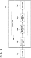
- FIG. 2 is a schematic block diagram showing the arrangement of the display apparatus 30.
- a display apparatus 30 includes an obtainment unit 302, a control unit 304, and a display unit 306.
- the obtainment unit 302 has a function of communicating with the motorcycle 1.
- the obtainment unit 302 obtains the information related to the driving state of the rider D from the detector 16 of the motorcycle 1, that is, the information indicating the load on the rider D in this embodiment and transmits the obtained information to the control unit 304.
- the control unit 304 includes a CPU, a memory, and the like and controls the overall (each unit of) display apparatus 30.
- the control unit 304 controls the display mode of the image showing the vehicle information related to the motorcycle 1, which is to be superimposed and provided on the foreground of the motorcycle 1, based on the information indicating the load on the rider D obtained by the obtainment unit 302.
- the control unit 304 includes, for example, as shown in Fig. 2 , an information processing unit 304a that creates the content of the vehicle information related to the motorcycle 1 in accordance with the pieces of information indicating the load on the rider D and an image generation unit 304b that generates image data which includes the content created by the information processing unit 304a.
- the display unit 306 displays, to the rider D, the image showing the vehicle information related to the motorcycle 1 under the control of the control unit 304.
- the display unit 306 displays the image by projecting, to the shield 21 of the helmet 20, an image corresponding to the image data generated by the image generation unit 304b and superimposing the image on the foreground of the motorcycle 1.
- the field of view of the rider D must be ensured in accordance with the state of the rider D so that the attention of the rider D will not be directed too much to the image. More specifically, there are cases in which the field of view of the rider D must be prioritized over (the image showing) the vehicle information related to the motorcycle 1 in accordance with the driving state (load state) of the rider D.
- the control unit 304 that controls the display mode of the image showing the vehicle information related to the motorcycle 1 is provided in this embodiment.
- Fig. 3 is a view showing an example of a foreground FG (the field of view of the rider D) of the motorcycle 1 and an image IMS showing the vehicle information related to the motorcycle 1 which is superimposed and provided on the foreground of the motorcycle 1.
- the image IMS is the standard image to be superimposed and provided on the foreground FG on the motorcycle 1 when the driving state of the rider D is in the normal state, that is, when the load on the rider D is equal to or smaller than a threshold.
- the image IMS includes a plurality of partial images each indicating a different piece of the plurality of pieces of vehicle information.
- the image IMS includes a first partial image IM1, a second partial image IM2, a third partial image IM3, a fourth partial image IM4, and a fifth partial image IM5.
- Each of the plurality of pieces of vehicle information has a priority indicating the degree of priority of the information to be provided to the rider D.
- the plurality of pieces of vehicle information include, in descending order of priority, information related to the safety of the motorcycle 1, information related to the route of the motorcycle 1, information related to the traveling speed of the motorcycle 1, and information related to a traffic sign at the traveling position of the motorcycle 1.
- the first partial image IM1 indicates "straight forward” as the information related to the route of the motorcycle 1
- the second partial image IM2 indicates “50 km/h” as the information related to the traveling speed of the motorcycle 1
- the third partial image IM3 indicates "speed limit 60 km/h” as the information related to the traffic sign at the traveling position of the motorcycle 1.
- the image IMS may include the fourth partial image IM4 indicating "xx Road” as information related to the road of the traveling position of the motorcycle 1, the fifth partial image IM5 indicating "Track no. 1" as information related to the music being played on the motorcycle 1.
- the control unit 304 In a case in which the load on the rider D obtained by the obtainment unit 302 is equal to or smaller than the threshold, the control unit 304 superimposes and provides the image IMS (standard image) shown in Fig. 3 on the foreground FG of the motorcycle 1.
- the control unit 304 erases at a part of the image IMS, for example, some of the first partial image IM1 to fifth partial image IM5, superimposed and provided on the foreground FG of the motorcycle 1. This can prioritize (ensure) the field of view of the rider D than the vehicle information related to the motorcycle 1 in accordance with the state of the rider D.
- the rider D has a large load, it can prevent the rider D from directing too much attention to the vehicle information and allow the rider D to focus on driving.
- threshold is related to the safety of driving the motorcycle 1, it is preferable for threshold to basically be set in advance.
- the threshold may be settable (changeable) by an operation by the rider D. In this case, however, the rider D needs to not set the threshold too small.
- the control unit 304 erases at least a part of the image IMS which is superimposed and provided on the foreground FG of the motorcycle 1 so that a portion where the image shows the vehicle information of the motorcycle 1 is superimposed on the foreground FG of the motorcycle 1 will become smaller as the load on the rider D obtained by the obtainment unit 302 increases.
- the control unit 304 erases the fifth partial image IM5 from the image IMS
- the control unit erases the fourth partial image IM4 and the third partial image IM3 in addition to the fifth partial image IM5 from the image IMS (that is, the control unit increase the number of partial images to be erased from the image IMS).
- the visual field of the rider D can be prioritized stepwise in accordance with the magnitude of the load on the rider D, and it possible to both provide the vehicle information related to the motorcycle 1 and ensure the visual field of the rider D.
- the control unit 304 can start to sequentially erase a partial image from a partial image with low priority among the plurality of partial images included in the image IMS. For example, in this embodiment, partial images are erased, from the image IMS, in the order of the fifth partial image IM5, the fourth partial image IM4, the third partial image IM3, the second partial image IM2, and the first partial image IM1.
- the control unit 304 may make the size of the image, showing the vehicle information related to the motorcycle 1 which is superimposed and provided on the foreground FG of the motorcycle 1, be smaller than the size of the image IMS, which is superimposed and provided on the foreground FG of the motorcycle 1 when the load on the rider D is equal to or smaller than the threshold.
- the control unit 304 may make the size of the image, showing the vehicle information related to the motorcycle 1 which is superimposed and provided on the foreground FG of the motorcycle 1, be smaller than the size of the image IMS, which is superimposed and provided on the foreground FG of the motorcycle 1 when the load on the rider D is equal to or smaller than the threshold.
- control unit 304 can decrease the size of the image which shows the vehicle information related to the motorcycle 1 and is superimposed and provided on the foreground FG of the motorcycle 1 as the load on the rider D obtained by the obtainment unit 302 increases. This can prioritize the field of view of the rider D stepwise in accordance with the magnitude of the load on the rider D.
- the control unit 304 may change the position of the image, which shows the vehicle information related to the motorcycle 1 and is superimposed and provided on the foreground FG of the motorcycle 1, based on the direction of the load acting on the rider D obtained by the obtainment unit 302. More specifically, the control unit 304 first determines whether the direction of the load acting on the rider D is rightward or leftward with respect to the direction of the field of view of the rider D. In this determination, for example, the handle steering operation of the rider D which is detected by the detector 16 and the like are used. If the direction of the load is rightward, the control unit changes the position of the image, which shows the vehicle information related to the motorcycle 1 and is superimposed and provided on the foreground FG of the motorcycle 1, toward the left.
- the position of the image which shows the vehicle information related to the motorcycle 1 and is superimposed and provided on the foreground FG of the motorcycle 1, is changed rightward by the control unit. This can ensure the field of view of the rider D with respect to the direction of the load acting on the rider D.
- the amount of vehicle information displayed on the upper part of the image which shows the vehicle information related to the motorcycle 1 and is superimposed and provided on the foreground FG of the motorcycle 1
- the amount of vehicle information displayed on the upper part of a standard image for example, the image IMS shown in Fig. 3
- This can ensure the upper part of the field of view of the rider D which is generally needed when the motorcycle 1 has a high traveling speed.
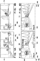
- Fig. 4A is a view showing an example of an image IMA which shows the vehicle information related to the motorcycle 1 and is superimposed and provided on the foreground FG of the motorcycle 1 in a case in which the motorcycle 1 is to enter an intersection and turn right.
- the load on the rider D increases (becomes larger than the threshold) for the rider D to safely drive the motorcycle 1.
- the control unit 304 erases the fifth partial image IM5, the fourth partial image IM4, the third partial image IM3, and the second partial image IM2 from the image IMS shown in Fig. 3 and superimposes and provides, on the foreground FG of the motorcycle 1, the image IMA which includes the first partial image IM1 indicating "turn right" as information related to the route of the motorcycle 1.
- the image IMA includes a sixth partial image IM6 indicating "ITS (Intelligent Transport System) display” as information related to the safety of the motorcycle 1.
- ITS Intelligent Transport System
- Fig. 4B is a view showing an example of an image 1MB which shows the vehicle information related to the motorcycle 1 and is superimposed and provided on the foreground FG of the motorcycle 1 in a case in which the motorcycle 1 enters an intersection and makes a turn.
- the load acting on the rider D is larger than that a case in which the motorcycle 1 is to enter the intersection and turn right.
- the control unit 304 superimposes and provides, on the foreground FG of the motorcycle 1, the image 1MB which is obtained by erasing the fifth partial image IM5, the fourth partial image IM4, the third partial image IM3, the second partial image IM2, and the first partial image IM1 from the image IMS shown in Fig. 3 .
- the sixth partial image IM6 is included on the left side in the image 1MB since a case in which the motorcycle 1 makes a turn from the right side has been assumed (a case in which the direction of the load acting on the rider D is rightward with respect to the direction of the field of view of the rider D).
- Fig. 4C is a view showing an example of an image IMC which shows the vehicle information related to the motorcycle 1 and is superimposed and provided on the foreground FG of the motorcycle 1 in a case in which the motorcycle 1 travels straight at low speed.
- the control unit 304 superimposes and provides the image IMC, which includes the first partial image IM1, the second partial image IM2, the third partial image IM3, fourth partial image IM4, and the fifth partial image IM5, on the foreground FG of the motorcycle 1 in the same manner as the image IMS shown in Fig. 3 .
- the first partial image IM1 indicates "in 400 m, turn right" as information related to the route of motorcycle 1.
- Fig. 4D is a view showing an example of an image IMD which shows the vehicle information related to the motorcycle 1 and is superimposed and provided on the foreground FG of the motorcycle 1 in a case in which the motorcycle 1 travels straight at a high speed.
- the load on the rider D is larger than that when the motorcycle 1 travels straight at a low speed.
- the control unit 304 superimposes and provides, on the foreground FG of the motorcycle 1, the image IMD which includes the second partial image IM2 and the third partial image IM3 but from which the fifth partial image IM5, the fourth partial image IM4, and the first partial image IM1 have been erased from the image IMS shown in Fig. 3 .
- the amount of vehicle information on the upper part of the image IMD is made less than the amount of vehicle information on the upper part of the image IMC.
- step S502 the obtainment unit 302 obtains, from the detector 16 of the motorcycle 1, information indicating the load on the rider D as information related to the driving state of the rider D.
- step S504 the control unit 304 determines whether the load on the rider D obtained in step S502 is larger than the threshold. If the load on the rider D is equal to or smaller than the threshold, the control unit 304 superimposes and provides, in step S506, the image IMS (standard image) shown in Fig. 3 on the foreground FG of the motorcycle 1.
- the control unit 304 erases, in step S508, at least a part of the image IMS (standard image) shown in Fig 3 and superimposes and provides, for example, the image IMA shown in Fig. 4A or the image 1MB shown in Fig. 4B on the foreground FG of the motorcycle 1.
- the present invention is advantageous in reducing the load on the rider D during driving of the motorcycle 1.
- a display control apparatus that has the function of the obtainment unit 302 and the function of the control unit 304 and controls a display apparatus that includes only the display unit 306 also forms an aspect of the present invention.
- the present invention is not limited to this.
- the image which shows the vehicle information related to the motorcycle 1 may be superimposed and displayed on the foreground of the motorcycle 1 via a member that has a function of displaying the image showing the vehicle information such as, for example, an eyeglass (eyewear) type member, a monocle type member, or a sun visor of the motorcycle (vehicle) 1.
- the present invention is not limited to a straddle type vehicle and is applicable to a scooter, a bicycle, a motor trike, or an automobile.
- the present invention provides a display apparatus that provides, to a driver of a vehicle, an image showing vehicle information related to the vehicle by superimposing the image on a foreground of the vehicle, the apparatus including obtainment means for obtaining information related to a driving state of the driver, and control means for controlling a display mode of the image based on the information obtained by the obtainment means.
Landscapes
- Engineering & Computer Science (AREA)
- Mechanical Engineering (AREA)
- Transportation (AREA)
- Chemical & Material Sciences (AREA)
- Combustion & Propulsion (AREA)
- Physics & Mathematics (AREA)
- General Physics & Mathematics (AREA)
- Theoretical Computer Science (AREA)
- Optics & Photonics (AREA)
- Multimedia (AREA)
- Instrument Panels (AREA)
- Traffic Control Systems (AREA)
- Navigation (AREA)
- Controls And Circuits For Display Device (AREA)
- User Interface Of Digital Computer (AREA)
Abstract
Description
- The present invention relates to a display apparatus, a display control apparatus, and a vehicle.
- In recent years, in a four-wheeled vehicle, there is available a head-up display that provides, to a driver, basic information related to the vehicle by projecting (displaying) an image (an image which forms at an infinite point) indicating the information related to the vehicle onto the windshield and superimposing the image on the normal field of view (the foreground of the vehicle) of the driver. There is also a demand for this technique to be implemented in a two-wheeled vehicle, and for example, the application of a head wearable display apparatus called a head-mounted display to a two-wheeled vehicle is being considered. International Publication No.
2015/125363 discloses a technique of determining (controlling) the luminance of light emitted from a display apparatus, based on the illuminance (illuminance information) of light that enters the display apparatus from the outside, in order to improve the visibility of an image in accordance with various kinds of peripheral situations. - In vehicles such as two-wheeled vehicles and four-wheeled vehicles, depending on the state of the load acting on the driver, there are situations in which the normal field of view of the driver must be prioritized over (an image showing) the information related to the vehicle. However, since the technique disclosed in International Publication No.
2015/125363 does not consider a display mode change operation which takes into account the load on the driver of the vehicle, direct application of this technique is difficult. - The present invention provides, in a display apparatus that provides an image by superimposing the image on the foreground of a vehicle, a technique advantageous in both providing vehicle information related to the vehicle and ensuring the field of view of a driver.
- The present invention in its first aspect provides a display apparatus as specified in claims 1 to 16.
- The present invention in its second aspect provides a display control apparatus as specified in claim 17.
- The present invention in its third aspect provides a vehicle as specified in claim 18.
- Further objects or other aspects of the present invention will become apparent by the preferred embodiment to be described below with reference to the accompanying drawings.
-
-
Fig. 1 is a schematic side view showing a motorcycle and a rider according to an embodiment of the present invention. -
Fig. 2 is a schematic block diagram showing the arrangement of a display apparatus according to the embodiment of the present invention. -
Fig. 3 is a view showing an example of a foreground (the field of view of the rider) of the motorcycle and an image which is superimposed and provided on the foreground of the motorcycle and shows vehicle information related to the motorcycle. -
Figs. 4A to 4D are views showing specific examples of display mode control of the image which shows the vehicle information related to the motorcycle. -
Fig. 5 is a flowchart for explaining processing for controlling the display mode of the image which shows the vehicle information related to the motorcycle. - A preferred embodiment of the present invention will be described below with reference to the accompanying drawings. Note that the same reference numerals denote the same components throughout the drawings and a repetitive description thereof will be omitted.
-
Fig. 1 is a schematic side view showing a rider D and a motorcycle 1 according to an embodiment of the present invention. The motorcycle 1 is a straddle type vehicle ridden by the rider D. The motorcycle 1 includes avehicle body frame 11 which serves as the framework of the vehicle, afront fork 12 which is supported by thevehicle body frame 11, anengine 13, aseat 14, aswing arm 15, and adetector 16. - The
vehicle body frame 11 includes, for example, a head pipe that steerably supports thefront fork 12, a main frame extending downward in a rear-diagonal direction from the lower portion of the head pipe, a center frame extending downward from the rear end of the main frame to the rear side, a seat rail extending upward from the rear end of the main frame to the rear side, a down frame extending from the front end of the main frame in a lower rear-diagonal direction, and an upper frame extending downward, to the rear side, from the upper portion of the head pipe to the main frame. - A
handlebar 121 is supported on the upper end of thefront fork 12, and afront wheel 123 is supported via anaxel shaft 122 on the lower end of thefront fork 12. Theengine 13 includes, for example, a crank case and a cylinder portion arranged so as to tilt forwardly from the crank case. Note that a transmission may be integrally arranged in the rear portion of the crank case. Theseat 14 is arranged on the upper portion of the seat rail. Theswing arm 15 is supported by the center frame so as to be vertically swingable, and the rear end of theswing arm 15 supports arear wheel 151 via anaxel shaft 152. - The
detector 16 has a function of detecting information related to the driving state of the rider D. In this embodiment, thedetector 16 detects, as the information related to the driving state, information indicating the load on the rider D. Here, the information indicating the load on the rider D includes, for example, information indicating the traveling speed of the motorcycle (vehicle) 1, information indicating the acceleration of the traveling motorcycle 1, information indicating the bank angle of the traveling motorcycle 1, information indicating the handle operation (that is, steering of the handlebar 121) by the rider D, information indicating the brake operation by the rider D, and the like. These pieces of information can be detected by the various kinds of sensors (for example, a speed sensor, an acceleration sensor, a gyro sensor, a sensor to detect the driving operation (steering), and the like) provided in the motorcycle 1. The information indicating the load on the rider D also includes information indicating the speed of the head of the rider D during traveling and information indicating the acceleration of the head of the rider D during traveling. These pieces of information can be detected by, for example, arranging a position sensor or the like that detects the position of the head (a helmet 20) of the rider D on the motorcycle 1. In addition, information indicating the load on the rider D includes information that indicates the traveling position of the motorcycle 1 which includes at least one piece of information indicating the radius of curvature of the road on which the motorcycle 1 is traveling, information indicating that the traveling position of the motorcycle 1 is at an intersection, and information indicating that the traveling position of the motorcycle 1 is in an area with high incidence of accidents. These pieces of information can be detected by a GPS arranged in the motorcycle 1. Hence, although thedetector 16 is illustrated as if it is arranged in one part of the motorcycle 1 inFig. 1 , various kinds of sensors are arranged in respective parts of the motorcycle 1 in reality, and at least one of the pieces of information described above is detected. - The rider D wears the helmet 20, sits on the
seat 14, and drives the motorcycle 1 via thehandlebar 121. The helmet 20 has the function of protecting the head (preventing or reducing an external injury to the head) of the rider D at the time of an accident or fall while the rider D is riding the motorcycle 1. In this embodiment, adisplay apparatus 30 for providing, to the rider D of the motorcycle (vehicle) 1, vehicle information related to the motorcycle 1 has been arranged in the helmet 20. Thedisplay apparatus 30 provides an image showing the vehicle information related to the motorcycle 1 by projecting the image onto ashield 21 of the helmet 20 and superimposing the image on the foreground (that is the field of view of the rider D) of the motorcycle 1. In this manner, thedisplay apparatus 30 is implemented as a display apparatus worn on the head of the rider D, that is, a so-called head-mounted display in this embodiment. - The arrangement of the
display apparatus 30 will be described with reference toFig. 2. Fig. 2 is a schematic block diagram showing the arrangement of thedisplay apparatus 30. Adisplay apparatus 30 includes anobtainment unit 302, acontrol unit 304, and adisplay unit 306. - The
obtainment unit 302 has a function of communicating with the motorcycle 1. Theobtainment unit 302 obtains the information related to the driving state of the rider D from thedetector 16 of the motorcycle 1, that is, the information indicating the load on the rider D in this embodiment and transmits the obtained information to thecontrol unit 304. - The
control unit 304 includes a CPU, a memory, and the like and controls the overall (each unit of)display apparatus 30. In this embodiment, thecontrol unit 304 controls the display mode of the image showing the vehicle information related to the motorcycle 1, which is to be superimposed and provided on the foreground of the motorcycle 1, based on the information indicating the load on the rider D obtained by theobtainment unit 302. Thecontrol unit 304 includes, for example, as shown inFig. 2 , aninformation processing unit 304a that creates the content of the vehicle information related to the motorcycle 1 in accordance with the pieces of information indicating the load on the rider D and animage generation unit 304b that generates image data which includes the content created by theinformation processing unit 304a. - The
display unit 306 displays, to the rider D, the image showing the vehicle information related to the motorcycle 1 under the control of thecontrol unit 304. In this embodiment, thedisplay unit 306 displays the image by projecting, to theshield 21 of the helmet 20, an image corresponding to the image data generated by theimage generation unit 304b and superimposing the image on the foreground of the motorcycle 1. - When the image showing the vehicle information related to the motorcycle 1 is to be superimposed on the foreground of the motorcycle 1 and displayed as in the manner of the
display apparatus 30 according to this embodiment, the field of view of the rider D must be ensured in accordance with the state of the rider D so that the attention of the rider D will not be directed too much to the image. More specifically, there are cases in which the field of view of the rider D must be prioritized over (the image showing) the vehicle information related to the motorcycle 1 in accordance with the driving state (load state) of the rider D. Hence, as described above, thecontrol unit 304 that controls the display mode of the image showing the vehicle information related to the motorcycle 1 is provided in this embodiment. - A control operation of the display mode of the image showing the vehicle information related to the motorcycle 1 in the
control unit 304 will be described hereinafter.Fig. 3 is a view showing an example of a foreground FG (the field of view of the rider D) of the motorcycle 1 and an image IMS showing the vehicle information related to the motorcycle 1 which is superimposed and provided on the foreground of the motorcycle 1. The image IMS is the standard image to be superimposed and provided on the foreground FG on the motorcycle 1 when the driving state of the rider D is in the normal state, that is, when the load on the rider D is equal to or smaller than a threshold. - The image IMS includes a plurality of partial images each indicating a different piece of the plurality of pieces of vehicle information. In
Fig. 3 , the image IMS includes a first partial image IM1, a second partial image IM2, a third partial image IM3, a fourth partial image IM4, and a fifth partial image IM5. Each of the plurality of pieces of vehicle information has a priority indicating the degree of priority of the information to be provided to the rider D. For example, the plurality of pieces of vehicle information include, in descending order of priority, information related to the safety of the motorcycle 1, information related to the route of the motorcycle 1, information related to the traveling speed of the motorcycle 1, and information related to a traffic sign at the traveling position of the motorcycle 1. In this embodiment, the first partial image IM1 indicates "straight forward" as the information related to the route of the motorcycle 1, the second partial image IM2 indicates "50 km/h" as the information related to the traveling speed of the motorcycle 1, and the third partial image IM3 indicates "speed limit 60 km/h" as the information related to the traffic sign at the traveling position of the motorcycle 1. Additionally, as other pieces of information, the image IMS may include the fourth partial image IM4 indicating "xx Road" as information related to the road of the traveling position of the motorcycle 1, the fifth partial image IM5 indicating "Track no. 1" as information related to the music being played on the motorcycle 1. - In a case in which the load on the rider D obtained by the
obtainment unit 302 is equal to or smaller than the threshold, thecontrol unit 304 superimposes and provides the image IMS (standard image) shown inFig. 3 on the foreground FG of the motorcycle 1. When the driving state of the rider D changes and the load on the rider D obtained by theobtainment unit 302 becomes larger than the threshold, thecontrol unit 304 erases at a part of the image IMS, for example, some of the first partial image IM1 to fifth partial image IM5, superimposed and provided on the foreground FG of the motorcycle 1. This can prioritize (ensure) the field of view of the rider D than the vehicle information related to the motorcycle 1 in accordance with the state of the rider D. Hence, for example, when the rider D has a large load, it can prevent the rider D from directing too much attention to the vehicle information and allow the rider D to focus on driving. - Here, since the above-described threshold is related to the safety of driving the motorcycle 1, it is preferable for threshold to basically be set in advance. However, the threshold may be settable (changeable) by an operation by the rider D. In this case, however, the rider D needs to not set the threshold too small.
- The
control unit 304 erases at least a part of the image IMS which is superimposed and provided on the foreground FG of the motorcycle 1 so that a portion where the image shows the vehicle information of the motorcycle 1 is superimposed on the foreground FG of the motorcycle 1 will become smaller as the load on the rider D obtained by theobtainment unit 302 increases. For example, when the load on the rider D is a first load, thecontrol unit 304 erases the fifth partial image IM5 from the image IMS, and when the load on the rider D is a second load larger than the first load, the control unit erases the fourth partial image IM4 and the third partial image IM3 in addition to the fifth partial image IM5 from the image IMS (that is, the control unit increase the number of partial images to be erased from the image IMS). As a result, the visual field of the rider D can be prioritized stepwise in accordance with the magnitude of the load on the rider D, and it possible to both provide the vehicle information related to the motorcycle 1 and ensure the visual field of the rider D. - Note that when at least a part of the image IMS superimposed and provided on the foreground FG of the motorcycle 1 is to be erased in accordance with the load on the rider D, the
control unit 304 can start to sequentially erase a partial image from a partial image with low priority among the plurality of partial images included in the image IMS. For example, in this embodiment, partial images are erased, from the image IMS, in the order of the fifth partial image IM5, the fourth partial image IM4, the third partial image IM3, the second partial image IM2, and the first partial image IM1. In this manner, by erasing the partial images from those with low priority, pieces of information such as the information related to the safety of the motorcycle 1 and the like can be left on the image IMS even when the load on the rider D is equal to or larger than the threshold if the load is not too large. - If the load on the rider D obtained by the
obtainment unit 302 is larger than threshold, thecontrol unit 304 may make the size of the image, showing the vehicle information related to the motorcycle 1 which is superimposed and provided on the foreground FG of the motorcycle 1, be smaller than the size of the image IMS, which is superimposed and provided on the foreground FG of the motorcycle 1 when the load on the rider D is equal to or smaller than the threshold. As a result, it is possible to provide the vehicle information related to the motorcycle 1 in accordance with the state of the rider D while ensuring the field of view of the rider D. - Note that the
control unit 304 can decrease the size of the image which shows the vehicle information related to the motorcycle 1 and is superimposed and provided on the foreground FG of the motorcycle 1 as the load on the rider D obtained by theobtainment unit 302 increases. This can prioritize the field of view of the rider D stepwise in accordance with the magnitude of the load on the rider D. - The
control unit 304 may change the position of the image, which shows the vehicle information related to the motorcycle 1 and is superimposed and provided on the foreground FG of the motorcycle 1, based on the direction of the load acting on the rider D obtained by theobtainment unit 302. More specifically, thecontrol unit 304 first determines whether the direction of the load acting on the rider D is rightward or leftward with respect to the direction of the field of view of the rider D. In this determination, for example, the handle steering operation of the rider D which is detected by thedetector 16 and the like are used. If the direction of the load is rightward, the control unit changes the position of the image, which shows the vehicle information related to the motorcycle 1 and is superimposed and provided on the foreground FG of the motorcycle 1, toward the left. On the other hand, if the direction of the load is leftward, the position of the image, which shows the vehicle information related to the motorcycle 1 and is superimposed and provided on the foreground FG of the motorcycle 1, is changed rightward by the control unit. This can ensure the field of view of the rider D with respect to the direction of the load acting on the rider D. - In a case in which the information indicating the load on the rider D includes the information indicating the traveling speed of the motorcycle 1 and the traveling speed of the motorcycle 1 obtained by the
obtainment unit 302 is higher than a predetermined speed, the amount of vehicle information displayed on the upper part of the image, which shows the vehicle information related to the motorcycle 1 and is superimposed and provided on the foreground FG of the motorcycle 1, will be made smaller than the amount of vehicle information displayed on the upper part of a standard image (for example, the image IMS shown inFig. 3 ) which is to be superimposed and provided on the foreground FG of the motorcycle 1 when the traveling speed of the motorcycle 1 is a predetermined speed or less. This can ensure the upper part of the field of view of the rider D which is generally needed when the motorcycle 1 has a high traveling speed. - Here, a more specific example of the control of the display mode of the image which shows the vehicle information related to the motorcycle 1 by the
control unit 304 will be described with reference toFigs. 4A to 4D. Fig. 4A is a view showing an example of an image IMA which shows the vehicle information related to the motorcycle 1 and is superimposed and provided on the foreground FG of the motorcycle 1 in a case in which the motorcycle 1 is to enter an intersection and turn right. When the motorcycle 1 is to enter an intersection and turn right, the load on the rider D increases (becomes larger than the threshold) for the rider D to safely drive the motorcycle 1. Hence, as shown inFig. 4A , thecontrol unit 304 erases the fifth partial image IM5, the fourth partial image IM4, the third partial image IM3, and the second partial image IM2 from the image IMS shown inFig. 3 and superimposes and provides, on the foreground FG of the motorcycle 1, the image IMA which includes the first partial image IM1 indicating "turn right" as information related to the route of the motorcycle 1. Note that the image IMA includes a sixth partial image IM6 indicating "ITS (Intelligent Transport System) display" as information related to the safety of the motorcycle 1. However, when the motorcycle 1 is to turn right, the position of the sixth partial image IM6 may be changed leftward since the direction of the load acting on the rider D is rightward with respect to the field of view of the rider D. -
Fig. 4B is a view showing an example of an image 1MB which shows the vehicle information related to the motorcycle 1 and is superimposed and provided on the foreground FG of the motorcycle 1 in a case in which the motorcycle 1 enters an intersection and makes a turn. When the motorcycle 1 is to enter the intersection and make a turn, the load acting on the rider D is larger than that a case in which the motorcycle 1 is to enter the intersection and turn right. Hence, as shown inFig. 4B , thecontrol unit 304 superimposes and provides, on the foreground FG of the motorcycle 1, the image 1MB which is obtained by erasing the fifth partial image IM5, the fourth partial image IM4, the third partial image IM3, the second partial image IM2, and the first partial image IM1 from the image IMS shown inFig. 3 . Note that the sixth partial image IM6 is included on the left side in the image 1MB since a case in which the motorcycle 1 makes a turn from the right side has been assumed (a case in which the direction of the load acting on the rider D is rightward with respect to the direction of the field of view of the rider D). -
Fig. 4C is a view showing an example of an image IMC which shows the vehicle information related to the motorcycle 1 and is superimposed and provided on the foreground FG of the motorcycle 1 in a case in which the motorcycle 1 travels straight at low speed. When the motorcycle 1 travels straight at low speed, the load on the rider D is not large. Hence, as shown inFig. 4C , thecontrol unit 304 superimposes and provides the image IMC, which includes the first partial image IM1, the second partial image IM2, the third partial image IM3, fourth partial image IM4, and the fifth partial image IM5, on the foreground FG of the motorcycle 1 in the same manner as the image IMS shown inFig. 3 . Note that inFig. 4C , the first partial image IM1 indicates "in 400 m, turn right" as information related to the route of motorcycle 1. -
Fig. 4D is a view showing an example of an image IMD which shows the vehicle information related to the motorcycle 1 and is superimposed and provided on the foreground FG of the motorcycle 1 in a case in which the motorcycle 1 travels straight at a high speed. When the motorcycle 1 travels straight at a high speed (at a speed higher than the predetermined traveling speed), the load on the rider D is larger than that when the motorcycle 1 travels straight at a low speed. Hence, as shown inFig. 4D , thecontrol unit 304 superimposes and provides, on the foreground FG of the motorcycle 1, the image IMD which includes the second partial image IM2 and the third partial image IM3 but from which the fifth partial image IM5, the fourth partial image IM4, and the first partial image IM1 have been erased from the image IMS shown inFig. 3 . In addition, the amount of vehicle information on the upper part of the image IMD is made less than the amount of vehicle information on the upper part of the image IMC. - The display processing of the
display apparatus 30, more specifically, the processing for controlling the display mode of the image which shows the vehicle information related to the motorcycle 1 will be described with reference toFig. 5 . In step S502, theobtainment unit 302 obtains, from thedetector 16 of the motorcycle 1, information indicating the load on the rider D as information related to the driving state of the rider D. In step S504, thecontrol unit 304 determines whether the load on the rider D obtained in step S502 is larger than the threshold. If the load on the rider D is equal to or smaller than the threshold, thecontrol unit 304 superimposes and provides, in step S506, the image IMS (standard image) shown inFig. 3 on the foreground FG of the motorcycle 1. On the other hand, if the load on the rider D is larger than the threshold, thecontrol unit 304 erases, in step S508, at least a part of the image IMS (standard image) shown inFig 3 and superimposes and provides, for example, the image IMA shown inFig. 4A or the image 1MB shown inFig. 4B on the foreground FG of the motorcycle 1. - In this manner, according to this embodiment, it is possible to both provide the vehicle information related to the motorcycle 1 and ensure the field of view of the rider D in accordance with the driving state of the rider D. Accordingly, since the field of view of the rider D can be prioritized (ensured) over the vehicle information related to the motorcycle 1 in accordance with the state of the motorcycle 1, the present invention is advantageous in reducing the load on the rider D during driving of the motorcycle 1.
- Although a case in which the
detector 16 for detecting the load on the rider D is arranged in the motorcycle 1 has been exemplified in this embodiment, a part or thewhole detector 16 may be arranged in thedisplay apparatus 30. A display control apparatus that has the function of theobtainment unit 302 and the function of thecontrol unit 304 and controls a display apparatus that includes only thedisplay unit 306 also forms an aspect of the present invention. - Furthermore, although a case in which the image which shows the vehicle information related to the motorcycle 1 is projected onto the
shield 21 of the helmet 20 has been exemplified in this embodiment, the present invention is not limited to this. The image which shows the vehicle information related to the motorcycle 1 may be superimposed and displayed on the foreground of the motorcycle 1 via a member that has a function of displaying the image showing the vehicle information such as, for example, an eyeglass (eyewear) type member, a monocle type member, or a sun visor of the motorcycle (vehicle) 1. -
- 1. The display apparatus according to the above-described embodiment is a display apparatus (30) that provides, to a driver (D) of a vehicle (1), an image showing vehicle information related to the vehicle by superimposing the image on a foreground (FG) of the vehicle, the apparatus comprising:
- obtainment means (302) for obtaining information related to a driving state of the driver; and
- control means (304) for controlling a display mode of the image based on the information obtained by the obtainment means.
- 2.The display apparatus (30) according to the above-described embodiment, wherein the information includes information which indicates a load on the driver (D).
According to this embodiment, it is possible to control the display mode of the image which shows the vehicle information related to the vehicle in accordance with the load on the driver. - 3.The display apparatus (30) according to the above-described embodiment, wherein in a case in which the load on the driver (D) included in the information obtained by the obtainment means (302) is larger than a threshold, the control means (304) erases at least a part of a standard image (IMS) which is to be superimposed and provided on the foreground (FG) of the vehicle (1) when the load on the driver is equal to or smaller than the threshold.
According to this embodiment, it is possible to prioritize (ensure) the field of view of the driver over the vehicle information related to the vehicle in accordance with the load on the driver. - 4.The display apparatus (30) according to the above-described embodiment, wherein the larger the magnitude of the load on the driver (D) which is included in the information obtained by the obtainment means (302) is, the control means (304) erases at least a part of the standard image (IMS) so as to make a part where the image is superimposed on the foreground (FG) of the vehicle smaller.
According to this embodiment, the field of view of the driver can be prioritized in accordance with the magnitude of the load on the driver. - 5.The display apparatus (30) according to the above-described embodiment, wherein the standard image (IMS) includes a plurality of partial images (IM1, IM2, IM3, IM4, and IM5) indicating a plurality of different pieces of vehicle information with different priority degrees from each other, and
the control means (304) starts to sequentially erase the partial image from a partial image which has a low priority degree among the plurality of partial images in accordance with the load on the driver (D) which is included in the information obtained by the obtainment means (302).
According to this embodiment, even in a case in which the load on the driver is equal to or larger than the threshold, the information related to the safety of the vehicle can be left on the image when the load is not very large. - 6.The display apparatus (30) according to the above-described embodiment, wherein the plurality of pieces of vehicle information include, in descending order of the priority degrees, information related to the safety of the vehicle (1), information related to a route of the vehicle, information related to a traveling speed of the vehicle, and information related to a traffic sign at a traveling position of the vehicle.
- 7.The display apparatus (30) according to the above-described embodiment, wherein in a case in which the load on the driver (D) included in the information obtained by the obtainment means (302) is larger than a threshold, the control means (304) decreases the size of an image, which is to be superimposed and provided on the foreground (FG) of the vehicle (1), to be smaller than the size of a standard image (IMS) which is to be superimposed and provided on the foreground of the vehicle when the load on the driver is equal to or smaller than the threshold.
According to this embodiment, the field of view of the driver can be ensured while providing the vehicle information related to the vehicle in accordance with the load on the driver. - 8.The display apparatus (30) according to the above-described embodiment, wherein the larger the load of the driver (D) included in the information obtained by the obtainment means (302) is, the control means (304) decreases the size of the image which is to be superimposed and provided on the foreground (FG) of the vehicle (1).
According to this embodiment, the field of view of the driver can be prioritized stepwise in accordance with the magnitude of the load on the driver. - 9.The display apparatus (30) according to the above-described embodiment, wherein the control means (304) changes a position of an image which is to be superimposed and provided on the foreground (FG) of the vehicle (1) based on a direction of the load acting on the driver (D) and included in the information obtained by the obtainment means (302).
According to this embodiment, it is possible to ensure the field of view of the driver in accordance with the direction of the load acting on the driver. - 10. The display apparatus (30) according to the above-described embodiment, wherein the control means (304) determines whether the direction of the load acting on the driver (D) and included in the information obtained by the obtainment means (302) is rightward or leftward with respect to a direction of the field of view of the driver, changes the position of the image which is to be superimposed and provided on the foreground (FG) of the vehicle (1) leftward when the direction of the load on the driver is rightward, and changes the position of the image which is to be superimposed and provided on the foreground of the vehicle rightward when the direction of the load on the driver is leftward.
According to this embodiment, it is possible to ensure the field of view of the driver with respect to the direction of the load acting on the driver. - 11. The display apparatus (30) according to the above-described embodiment,
wherein the vehicle (1) includes a straddle type vehicle, and
the display apparatus includes a display apparatus which is wearable on the head of the driver (D).
According to this embodiment, the display apparatus can be formed by a head-mounted display. - 12. The display apparatus (30) according to the above-described embodiment, wherein the information indicating the load on the driver (D) includes at least one piece of information indicating a traveling speed of the vehicle (1), information indicating the acceleration of the vehicle during traveling, information indicating a bank angle of the vehicle during traveling, information indicating a speed of the head of the driver during traveling, information indicating acceleration of the head of the driver during traveling, information indicating a traveling position of the vehicle, information indicating a handle operation by the driver, and information indicating a brake operation by the driver.
- 13. The display apparatus (30) according to the above-described embodiment, wherein the information indicating the traveling position of the vehicle (1) includes at least one of information indicating a radius of curvature of a road on which the vehicle is traveling, information indicating that the traveling position of the vehicle is at an intersection, and information indicating that the traveling position of the vehicle is at an area with a high incidence of accidents.
- 14. The display apparatus (30) according to the above-described embodiment, wherein in a case in which the information indicating the load on the driver (D) includes the information indicating the traveling speed of the vehicle (1), the control means (304) makes the amount of the vehicle information on an upper part of an image, which is to be superimposed and provided on the foreground of the vehicle, when the traveling speed of the vehicle included in the information obtained by the obtainment means (302) is higher than a predetermined traveling speed less than the amount of the vehicle information on an upper part of a standard image (IMS), which is to be superimposed and provided on the foreground of the vehicle, when the traveling speed of the vehicle is equal to or less than the predetermined traveling speed.
According to this embodiment, it is possible to ensure the upper part of the field of view of the driver which is generally necessary when the traveling speed of the vehicle is higher than the predetermined traveling speed. - 15. The display apparatus (30) according to the above-described embodiment, wherein the obtainment means (302) obtains information related to the load on the driver (D) from a detector (16) which is arranged on the vehicle (1) and is configured to detect the load on the driver.
- 16. The display apparatus (30) according to the above-described embodiment, wherein the obtainment means (302) includes a detector (16) configured to detect the load on the driver (D).
- 17. The above-described display control apparatus that controls a display apparatus (30) which provides, to a driver (D) of a vehicle (1), an image showing vehicle information related to the vehicle by superimposing the image on a foreground (FG) of the vehicle, the apparatus comprising:
- obtainment means (302) for obtaining information related to a driving state of the driver; and
- control means (304) for controlling a display mode of the image based on the information obtained by the obtainment means.
- 18. The above-described vehicle (1) comprising:
- display means (30, 306) for providing, to a driver (D) of the vehicle (1), an image showing information related to the vehicle by superimposing the image on a foreground (FG) of the vehicle;
- obtainment means (302) for obtaining information related to a driving state of the driver; and
- control means (304) for controlling a display mode of the image based on the information obtained by the obtainment means.
- According to this embodiment, it is possible to both provide the vehicle information related to the vehicle and ensure the field of view of the driver of the vehicle in accordance with the driving state of the driver.
- The preferred embodiment of the present invention has been described above. However, the present invention is not limited to this, as a matter of course, and various modifications and changes can be made within the spirit and scope of the present invention. For example, the present invention is not limited to a straddle type vehicle and is applicable to a scooter, a bicycle, a motor trike, or an automobile.
- The present invention provides a display apparatus that provides, to a driver of a vehicle, an image showing vehicle information related to the vehicle by superimposing the image on a foreground of the vehicle, the apparatus including obtainment means for obtaining information related to a driving state of the driver, and control means for controlling a display mode of the image based on the information obtained by the obtainment means.
Claims (18)
- A display apparatus (30) that provides, to a driver (D) of a vehicle (1), an image showing vehicle information related to the vehicle by superimposing the image on a foreground (FG) of the vehicle, the apparatus comprising:obtainment means (302) for obtaining information related to a driving state of the driver; andcontrol means (304) for controlling a display mode of the image based on the information obtained by the obtainment means.
- The apparatus according to claim 1, wherein the information includes information which indicates a load on the driver (D).
- The apparatus according to claim 2, wherein in a case in which the load on the driver (D) included in the information obtained by the obtainment means (302) is larger than a threshold, the control means (304) erases at least a part of a standard image (IMS) which is to be superimposed and provided on the foreground (FG) of the vehicle (1) when the load on the driver is equal to or smaller than the threshold.
- The apparatus according to claim 3, wherein the larger the magnitude of the load on the driver (D) which is included in the information obtained by the obtainment means (302) is, the control means (304) erases at least a part of the standard image (IMS) so as to make a part where the image is superimposed on the foreground (FG) of the vehicle smaller.
- The apparatus according to claim 3, wherein the standard image (IMS) includes a plurality of partial images (IM1, IM2, IM3, IM4, IM5) indicating a plurality of different pieces of vehicle information with different priority degrees from each other, and
the control means (304) starts to sequentially erase the partial image from a partial image which has a low priority degree among the plurality of partial images in accordance with the load on the driver (D) which is included in the information obtained by the obtainment means (302). - The apparatus according to claim 5, wherein the plurality of pieces of vehicle information include, in descending order of the priority degrees, information related to the safety of the vehicle (1), information related to a route of the vehicle, information related to a traveling speed of the vehicle, and information related to a traffic sign at a traveling position of the vehicle.
- The apparatus according to claim 2, wherein in a case in which the load on the driver (D) included in the information obtained by the obtainment means (302) is larger than a threshold, the control means (304) decreases the size of an image, which is to be superimposed and provided on the foreground (FG) of the vehicle (1), to be smaller than the size of a standard image (IMS) which is to be superimposed and provided on the foreground of the vehicle when the load on the driver is equal to or smaller than the threshold.
- The apparatus according to claim 7, wherein the larger the load of the driver (D) included in the information obtained by the obtainment means (302) is, the control means (304) decreases the size of the image which is to be superimposed and provided on the foreground (FG) of the vehicle (1).
- The apparatus according to claim 2, wherein the control means (304) changes a position of an image which is to be superimposed and provided on the foreground (FG) of the vehicle (1) based on a direction of the load acting on the driver (D) and included in the information obtained by the obtainment means (302).
- The apparatus according to claim 9, wherein the control means (304) determines whether the direction of the load acting on the driver (D) and included in the information obtained by the obtainment means (302) is rightward or leftward with respect to a direction of the field of view of the driver, changes the position of the image which is to be superimposed and provided on the foreground (FG) of the vehicle (1) leftward when the direction of the load on the driver is rightward, and changes the position of the image which is to be superimposed and provided on the foreground of the vehicle rightward when the direction of the load on the driver is leftward.
- The apparatus according to claim 2, wherein the vehicle (1) includes a straddle type vehicle, and
the display apparatus includes a display apparatus which is wearable on the head of the driver (D). - The apparatus according to claim 11, wherein the information indicating the load on the driver (D) includes at least one piece of information indicating a traveling speed of the vehicle (1), information indicating the acceleration of the vehicle during traveling, information indicating a bank angle of the vehicle during traveling, information indicating a speed of the head of the driver during traveling, information indicating acceleration of the head of the driver during traveling, information indicating a traveling position of the vehicle, information indicating a handle operation by the driver, and information indicating a brake operation by the driver.
- The apparatus according to claim 12, wherein the information indicating the traveling position of the vehicle (1) includes at least one of information indicating a radius of curvature of a road on which the vehicle is traveling, information indicating that the traveling position of the vehicle is at an intersection, and information indicating that the traveling position of the vehicle is at an area with a high incidence of accidents.
- The apparatus according to claim 12, wherein in a case in which the information indicating the load on the driver (D) includes the information indicating the traveling speed of the vehicle (1), the control means (304) makes the amount of the vehicle information on an upper part of an image, which is to be superimposed and provided on the foreground of the vehicle, when the traveling speed of the vehicle included in the information obtained by the obtainment means (302) is higher than a predetermined traveling speed less than the amount of the vehicle information on an upper part of a standard image (IMS), which is to be superimposed and provided on the foreground of the vehicle, when the traveling speed of the vehicle is equal to or less than the predetermined traveling speed.
- The apparatus according to claim 2, wherein the obtainment means (302) obtains information related to the load on the driver (D) from a detector (16) which is arranged on the vehicle (1) and is configured to detect the load on the driver.
- The apparatus according to claim 2, wherein the obtainment means (302) includes a detector (16) configured to detect the load on the driver (D).
- A display control apparatus that controls a display apparatus (30) which provides, to a driver (D) of a vehicle (1), an image showing vehicle information related to the vehicle by superimposing the image on a foreground (FG) of the vehicle, the apparatus comprising:obtainment means (302) for obtaining information related to a driving state of the driver; andcontrol means (304) for controlling a display mode of the image based on the information obtained by the obtainment means.
- A vehicle (1) comprising:display means (30, 306) for providing, to a driver (D) of the vehicle (1), an image showing information related to the vehicle by superimposing the image on a foreground (FG) of the vehicle;obtainment means (302) for obtaining information related to a driving state of the driver; andcontrol means (304) for controlling a display mode of the image based on the information obtained by the obtainment means.
Applications Claiming Priority (1)
| Application Number | Priority Date | Filing Date | Title |
|---|---|---|---|
| JP2017186785A JP2019061559A (en) | 2017-09-27 | 2017-09-27 | Display device, display control device and vehicle |
Publications (2)
| Publication Number | Publication Date |
|---|---|
| EP3461672A1 true EP3461672A1 (en) | 2019-04-03 |
| EP3461672B1 EP3461672B1 (en) | 2021-07-28 |
Family
ID=63556164
Family Applications (1)
| Application Number | Title | Priority Date | Filing Date |
|---|---|---|---|
| EP18193344.1A Active EP3461672B1 (en) | 2017-09-27 | 2018-09-10 | Display apparatus, display control apparatus, and vehicle |
Country Status (4)
| Country | Link |
|---|---|
| US (1) | US10762677B2 (en) |
| EP (1) | EP3461672B1 (en) |
| JP (1) | JP2019061559A (en) |
| CN (1) | CN109591699B (en) |
Cited By (3)
| Publication number | Priority date | Publication date | Assignee | Title |
|---|---|---|---|---|
| WO2021094168A1 (en) * | 2019-11-11 | 2021-05-20 | Psa Automobiles Sa | Method for displaying information on a human-machine interface of a motor vehicle, computer program product, human-machine interface, and motor vehicle |
| EP4079553A4 (en) * | 2019-12-20 | 2023-01-18 | NS West Inc. | DISPLAY UNIT ELECTROLUMINESCENT DEVICE |
| WO2023284961A1 (en) * | 2021-07-15 | 2023-01-19 | Lotus Tech Innovation Centre Gmbh | Computer-implemented method of adapting a graphical user interface of a human machine interface of a vehicle, computer program product, human machine interface, and vehicle |
Families Citing this family (11)
| Publication number | Priority date | Publication date | Assignee | Title |
|---|---|---|---|---|
| US20180334221A1 (en) * | 2017-05-16 | 2018-11-22 | Wen-Sung Lee | Power generation device for bicycle |
| JP2020050220A (en) * | 2018-09-28 | 2020-04-02 | ロベルト・ボッシュ・ゲゼルシャフト・ミト・ベシュレンクテル・ハフツングRobert Bosch Gmbh | Control device and control method |
| WO2021079497A1 (en) * | 2019-10-25 | 2021-04-29 | ヤマハ発動機株式会社 | Real-time information presentation control apparatus for leaning vehicle |
| JP7423341B2 (en) * | 2020-02-19 | 2024-01-29 | 本田技研工業株式会社 | Control device, vehicle, program, and control method |
| CN114684301B (en) * | 2020-04-07 | 2024-05-31 | 合肥工业大学 | Driving information display device and vehicle based on safety level |
| JP2022018014A (en) * | 2020-07-14 | 2022-01-26 | 日本精機株式会社 | Display device for motorcycle |
| US20220078588A1 (en) | 2020-09-06 | 2022-03-10 | Autotalks Ltd. | Method and apparatus for two-wheeler safety based on vehicular communications |
| DE102021101985A1 (en) * | 2021-01-28 | 2022-07-28 | Bayerische Motoren Werke Aktiengesellschaft | Method and device for providing reference points in the vicinity of a vehicle from the vehicle to a mobile terminal |
| CN113086067A (en) * | 2021-03-25 | 2021-07-09 | 九号智能(常州)科技有限公司 | Electric scooter and display control method, device, system and instrument thereof |
| JP2023058814A (en) * | 2021-10-14 | 2023-04-26 | ロベルト・ボッシュ・ゲゼルシャフト・ミト・ベシュレンクテル・ハフツング | Processing unit and processing method for information management system, and information management system |
| WO2023199896A1 (en) * | 2022-04-11 | 2023-10-19 | 日本精機株式会社 | Display device |
Citations (5)
| Publication number | Priority date | Publication date | Assignee | Title |
|---|---|---|---|---|
| EP0771686A2 (en) * | 1995-11-06 | 1997-05-07 | Toyota Jidosha Kabushiki Kaisha | Information display apparatus for vehicles |
| DE10322458A1 (en) * | 2003-05-16 | 2004-12-02 | Daimlerchrysler Ag | Method and device for influencing the stress of a driver in a motor vehicle |
| EP1515295A2 (en) * | 2003-08-22 | 2005-03-16 | Semiconductor Energy Laboratory Co., Ltd. | Light emitting device, driving support system, and helmet |
| DE102011111213A1 (en) * | 2011-08-20 | 2013-02-21 | GM Global Technology Operations LLC (n. d. Gesetzen des Staates Delaware) | Apparatus and method for outputting information |
| WO2015125363A1 (en) | 2014-02-21 | 2015-08-27 | ソニー株式会社 | Electronic apparatus and image providing method |
Family Cites Families (10)
| Publication number | Priority date | Publication date | Assignee | Title |
|---|---|---|---|---|
| JPH09304103A (en) * | 1996-05-15 | 1997-11-28 | Matsushita Electric Ind Co Ltd | Navigation device |
| JP2004219664A (en) * | 2003-01-14 | 2004-08-05 | Sumitomo Electric Ind Ltd | Information display system and information display method |
| JP2008014783A (en) * | 2006-07-05 | 2008-01-24 | Denso Corp | Vehicle navigation device |
| JP2008026075A (en) * | 2006-07-19 | 2008-02-07 | Sky Kk | Motorcycle navigation system |
| CN105474287A (en) * | 2013-08-19 | 2016-04-06 | 三菱电机株式会社 | Vehicle-mounted display control device |
| JP6361318B2 (en) * | 2014-06-25 | 2018-07-25 | 株式会社デンソー | VEHICLE IMAGE DISPLAY DEVICE AND VEHICLE IMAGE DISPLAY METHOD |
| JP6123761B2 (en) * | 2014-09-05 | 2017-05-10 | トヨタ自動車株式会社 | Vehicle display device |
| WO2017086380A1 (en) * | 2015-11-20 | 2017-05-26 | パイオニア株式会社 | Information display apparatus, control method, program, and storage medium |
| US10871655B2 (en) * | 2016-02-12 | 2020-12-22 | Maxell, Ltd. | Image display apparatus for vehicle |
| EP3438805B1 (en) * | 2016-03-31 | 2020-09-09 | Honda Motor Co., Ltd. | Image display apparatus and image display method |
-
2017
- 2017-09-27 JP JP2017186785A patent/JP2019061559A/en active Pending
-
2018
- 2018-09-06 US US16/122,905 patent/US10762677B2/en active Active
- 2018-09-10 EP EP18193344.1A patent/EP3461672B1/en active Active
- 2018-09-18 CN CN201811085386.5A patent/CN109591699B/en active Active
Patent Citations (5)
| Publication number | Priority date | Publication date | Assignee | Title |
|---|---|---|---|---|
| EP0771686A2 (en) * | 1995-11-06 | 1997-05-07 | Toyota Jidosha Kabushiki Kaisha | Information display apparatus for vehicles |
| DE10322458A1 (en) * | 2003-05-16 | 2004-12-02 | Daimlerchrysler Ag | Method and device for influencing the stress of a driver in a motor vehicle |
| EP1515295A2 (en) * | 2003-08-22 | 2005-03-16 | Semiconductor Energy Laboratory Co., Ltd. | Light emitting device, driving support system, and helmet |
| DE102011111213A1 (en) * | 2011-08-20 | 2013-02-21 | GM Global Technology Operations LLC (n. d. Gesetzen des Staates Delaware) | Apparatus and method for outputting information |
| WO2015125363A1 (en) | 2014-02-21 | 2015-08-27 | ソニー株式会社 | Electronic apparatus and image providing method |
Cited By (7)
| Publication number | Priority date | Publication date | Assignee | Title |
|---|---|---|---|---|
| WO2021094168A1 (en) * | 2019-11-11 | 2021-05-20 | Psa Automobiles Sa | Method for displaying information on a human-machine interface of a motor vehicle, computer program product, human-machine interface, and motor vehicle |
| CN114728584A (en) * | 2019-11-11 | 2022-07-08 | 标致雪铁龙汽车股份有限公司 | Method for displaying information on a human-machine interface of a motor vehicle, computer program product, human-machine interface and motor vehicle |
| DE102019217346B4 (en) | 2019-11-11 | 2023-12-07 | Psa Automobiles Sa | Method for displaying information on a human-machine interface of a motor vehicle, computer program product, human-machine interface and motor vehicle |
| CN114728584B (en) * | 2019-11-11 | 2026-03-10 | 标致雪铁龙汽车股份有限公司 | Method for displaying information on a human-machine interface of a motor vehicle, computer program product, human-machine interface and motor vehicle |
| EP4079553A4 (en) * | 2019-12-20 | 2023-01-18 | NS West Inc. | DISPLAY UNIT ELECTROLUMINESCENT DEVICE |
| US12078503B2 (en) | 2019-12-20 | 2024-09-03 | Ns West Inc. | Display light emitting device |
| WO2023284961A1 (en) * | 2021-07-15 | 2023-01-19 | Lotus Tech Innovation Centre Gmbh | Computer-implemented method of adapting a graphical user interface of a human machine interface of a vehicle, computer program product, human machine interface, and vehicle |
Also Published As
| Publication number | Publication date |
|---|---|
| US10762677B2 (en) | 2020-09-01 |
| EP3461672B1 (en) | 2021-07-28 |
| US20190096107A1 (en) | 2019-03-28 |
| CN109591699A (en) | 2019-04-09 |
| JP2019061559A (en) | 2019-04-18 |
| CN109591699B (en) | 2022-03-01 |
Similar Documents
| Publication | Publication Date | Title |
|---|---|---|
| US10762677B2 (en) | Display apparatus, display control apparatus, and vehicle | |
| US8325027B2 (en) | Safety light device | |
| KR101687543B1 (en) | Display apparatus and method for controlling the same | |
| JP6628411B2 (en) | Optical sensor arrangement structure for saddle type vehicle | |
| JP7065896B2 (en) | Saddle-type vehicle | |
| JP7411684B2 (en) | Rider support system and rider support system control method | |
| JP7450034B2 (en) | Control device for rider support system, rider support system, and control method for rider support system | |
| JP4767136B2 (en) | Information disclosure device | |
| JP2018012439A (en) | Rear view assist device | |
| JP2005306337A (en) | Information display device for moving body | |
| JP2017129406A (en) | Information processing device, smart glass and control method thereof, and computer program | |
| JP6861769B2 (en) | Display control device, display control method, and program | |
| EP1473215B1 (en) | Lamp system for motorcycles | |
| TW201307113A (en) | Bike computer for projection | |
| CN110319848B (en) | Output device | |
| JP2021037928A (en) | Rider support system and control method of rider support system | |
| US11932266B2 (en) | Rider-assistance system and control method for rider-assistance system | |
| JP4730880B2 (en) | Direction indication information display method and curve information display method for motorcycles | |
| US20210300497A1 (en) | Saddle ride type vehicle and control apparatus | |
| WO2024147051A1 (en) | Control device and control method | |
| JP7719881B2 (en) | Rider assistance system, data structure and control method | |
| JPH03186489A (en) | Head-up display for motorcycles | |
| JP2005271902A (en) | In-vehicle display controller | |
| JP2023093987A (en) | Control device and control method | |
| Boets et al. | Impact of a Head-Up Display on motorcycle riding: A pilot study using a motorcycle riding simulator |
Legal Events
| Date | Code | Title | Description |
|---|---|---|---|
| PUAI | Public reference made under article 153(3) epc to a published international application that has entered the european phase |
Free format text: ORIGINAL CODE: 0009012 |
|
| STAA | Information on the status of an ep patent application or granted ep patent |
Free format text: STATUS: REQUEST FOR EXAMINATION WAS MADE |
|
| 17P | Request for examination filed |
Effective date: 20180910 |
|
| AK | Designated contracting states |
Kind code of ref document: A1 Designated state(s): AL AT BE BG CH CY CZ DE DK EE ES FI FR GB GR HR HU IE IS IT LI LT LU LV MC MK MT NL NO PL PT RO RS SE SI SK SM TR |
|
| AX | Request for extension of the european patent |
Extension state: BA ME |
|
| STAA | Information on the status of an ep patent application or granted ep patent |
Free format text: STATUS: EXAMINATION IS IN PROGRESS |
|
| 17Q | First examination report despatched |
Effective date: 20191209 |
|
| GRAP | Despatch of communication of intention to grant a patent |
Free format text: ORIGINAL CODE: EPIDOSNIGR1 |
|
| STAA | Information on the status of an ep patent application or granted ep patent |
Free format text: STATUS: GRANT OF PATENT IS INTENDED |
|
| GRAJ | Information related to disapproval of communication of intention to grant by the applicant or resumption of examination proceedings by the epo deleted |
Free format text: ORIGINAL CODE: EPIDOSDIGR1 |
|
| STAA | Information on the status of an ep patent application or granted ep patent |
Free format text: STATUS: EXAMINATION IS IN PROGRESS |
|
| INTG | Intention to grant announced |
Effective date: 20201211 |
|
| RIN1 | Information on inventor provided before grant (corrected) |
Inventor name: NOGUCHI, KOHEI Inventor name: SENNO, MASAHARU Inventor name: TSUTSUMI, YOJIRO |
|
| INTC | Intention to grant announced (deleted) | ||
| GRAP | Despatch of communication of intention to grant a patent |
Free format text: ORIGINAL CODE: EPIDOSNIGR1 |
|
| STAA | Information on the status of an ep patent application or granted ep patent |
Free format text: STATUS: GRANT OF PATENT IS INTENDED |
|
| GRAJ | Information related to disapproval of communication of intention to grant by the applicant or resumption of examination proceedings by the epo deleted |
Free format text: ORIGINAL CODE: EPIDOSDIGR1 |
|
| GRAP | Despatch of communication of intention to grant a patent |
Free format text: ORIGINAL CODE: EPIDOSNIGR1 |
|
| GRAJ | Information related to disapproval of communication of intention to grant by the applicant or resumption of examination proceedings by the epo deleted |
Free format text: ORIGINAL CODE: EPIDOSDIGR1 |
|
| GRAP | Despatch of communication of intention to grant a patent |
Free format text: ORIGINAL CODE: EPIDOSNIGR1 |
|
| GRAJ | Information related to disapproval of communication of intention to grant by the applicant or resumption of examination proceedings by the epo deleted |
Free format text: ORIGINAL CODE: EPIDOSDIGR1 |
|
| INTG | Intention to grant announced |
Effective date: 20210202 |
|
| RIN1 | Information on inventor provided before grant (corrected) |
Inventor name: NOGUCHI, KOHEI Inventor name: SENNO, MASAHARU Inventor name: TSUTSUMI, YOJIRO |
|
| GRAP | Despatch of communication of intention to grant a patent |
Free format text: ORIGINAL CODE: EPIDOSNIGR1 |
|
| INTG | Intention to grant announced |
Effective date: 20210212 |
|
| INTG | Intention to grant announced |
Effective date: 20210224 |
|
| INTG | Intention to grant announced |
Effective date: 20210311 |
|
| GRAS | Grant fee paid |
Free format text: ORIGINAL CODE: EPIDOSNIGR3 |
|
| GRAA | (expected) grant |
Free format text: ORIGINAL CODE: 0009210 |
|
| STAA | Information on the status of an ep patent application or granted ep patent |
Free format text: STATUS: THE PATENT HAS BEEN GRANTED |
|
| AK | Designated contracting states |
Kind code of ref document: B1 Designated state(s): AL AT BE BG CH CY CZ DE DK EE ES FI FR GB GR HR HU IE IS IT LI LT LU LV MC MK MT NL NO PL PT RO RS SE SI SK SM TR |
|
| REG | Reference to a national code |
Ref country code: GB Ref legal event code: FG4D |
|
| REG | Reference to a national code |
Ref country code: CH Ref legal event code: EP |
|
| REG | Reference to a national code |
Ref country code: AT Ref legal event code: REF Ref document number: 1414437 Country of ref document: AT Kind code of ref document: T Effective date: 20210815 |
|
| REG | Reference to a national code |
Ref country code: IE Ref legal event code: FG4D |
|
| REG | Reference to a national code |
Ref country code: DE Ref legal event code: R096 Ref document number: 602018020695 Country of ref document: DE |
|
| REG | Reference to a national code |
Ref country code: LT Ref legal event code: MG9D |
|
| REG | Reference to a national code |
Ref country code: NL Ref legal event code: MP Effective date: 20210728 |
|
| REG | Reference to a national code |
Ref country code: AT Ref legal event code: MK05 Ref document number: 1414437 Country of ref document: AT Kind code of ref document: T Effective date: 20210728 |
|
| PG25 | Lapsed in a contracting state [announced via postgrant information from national office to epo] |
Ref country code: PT Free format text: LAPSE BECAUSE OF FAILURE TO SUBMIT A TRANSLATION OF THE DESCRIPTION OR TO PAY THE FEE WITHIN THE PRESCRIBED TIME-LIMIT Effective date: 20211129 Ref country code: NL Free format text: LAPSE BECAUSE OF FAILURE TO SUBMIT A TRANSLATION OF THE DESCRIPTION OR TO PAY THE FEE WITHIN THE PRESCRIBED TIME-LIMIT Effective date: 20210728 Ref country code: NO Free format text: LAPSE BECAUSE OF FAILURE TO SUBMIT A TRANSLATION OF THE DESCRIPTION OR TO PAY THE FEE WITHIN THE PRESCRIBED TIME-LIMIT Effective date: 20211028 Ref country code: BG Free format text: LAPSE BECAUSE OF FAILURE TO SUBMIT A TRANSLATION OF THE DESCRIPTION OR TO PAY THE FEE WITHIN THE PRESCRIBED TIME-LIMIT Effective date: 20211028 Ref country code: AT Free format text: LAPSE BECAUSE OF FAILURE TO SUBMIT A TRANSLATION OF THE DESCRIPTION OR TO PAY THE FEE WITHIN THE PRESCRIBED TIME-LIMIT Effective date: 20210728 Ref country code: LT Free format text: LAPSE BECAUSE OF FAILURE TO SUBMIT A TRANSLATION OF THE DESCRIPTION OR TO PAY THE FEE WITHIN THE PRESCRIBED TIME-LIMIT Effective date: 20210728 Ref country code: RS Free format text: LAPSE BECAUSE OF FAILURE TO SUBMIT A TRANSLATION OF THE DESCRIPTION OR TO PAY THE FEE WITHIN THE PRESCRIBED TIME-LIMIT Effective date: 20210728 Ref country code: SE Free format text: LAPSE BECAUSE OF FAILURE TO SUBMIT A TRANSLATION OF THE DESCRIPTION OR TO PAY THE FEE WITHIN THE PRESCRIBED TIME-LIMIT Effective date: 20210728 Ref country code: HR Free format text: LAPSE BECAUSE OF FAILURE TO SUBMIT A TRANSLATION OF THE DESCRIPTION OR TO PAY THE FEE WITHIN THE PRESCRIBED TIME-LIMIT Effective date: 20210728 Ref country code: ES Free format text: LAPSE BECAUSE OF FAILURE TO SUBMIT A TRANSLATION OF THE DESCRIPTION OR TO PAY THE FEE WITHIN THE PRESCRIBED TIME-LIMIT Effective date: 20210728 Ref country code: FI Free format text: LAPSE BECAUSE OF FAILURE TO SUBMIT A TRANSLATION OF THE DESCRIPTION OR TO PAY THE FEE WITHIN THE PRESCRIBED TIME-LIMIT Effective date: 20210728 |
|
| PG25 | Lapsed in a contracting state [announced via postgrant information from national office to epo] |
Ref country code: PL Free format text: LAPSE BECAUSE OF FAILURE TO SUBMIT A TRANSLATION OF THE DESCRIPTION OR TO PAY THE FEE WITHIN THE PRESCRIBED TIME-LIMIT Effective date: 20210728 Ref country code: LV Free format text: LAPSE BECAUSE OF FAILURE TO SUBMIT A TRANSLATION OF THE DESCRIPTION OR TO PAY THE FEE WITHIN THE PRESCRIBED TIME-LIMIT Effective date: 20210728 Ref country code: GR Free format text: LAPSE BECAUSE OF FAILURE TO SUBMIT A TRANSLATION OF THE DESCRIPTION OR TO PAY THE FEE WITHIN THE PRESCRIBED TIME-LIMIT Effective date: 20211029 |
|
| PG25 | Lapsed in a contracting state [announced via postgrant information from national office to epo] |
Ref country code: DK Free format text: LAPSE BECAUSE OF FAILURE TO SUBMIT A TRANSLATION OF THE DESCRIPTION OR TO PAY THE FEE WITHIN THE PRESCRIBED TIME-LIMIT Effective date: 20210728 |
|
| REG | Reference to a national code |
Ref country code: DE Ref legal event code: R097 Ref document number: 602018020695 Country of ref document: DE |
|
| REG | Reference to a national code |
Ref country code: CH Ref legal event code: PL |
|
| REG | Reference to a national code |
Ref country code: BE Ref legal event code: MM Effective date: 20210930 |
|
| PG25 | Lapsed in a contracting state [announced via postgrant information from national office to epo] |
Ref country code: SM Free format text: LAPSE BECAUSE OF FAILURE TO SUBMIT A TRANSLATION OF THE DESCRIPTION OR TO PAY THE FEE WITHIN THE PRESCRIBED TIME-LIMIT Effective date: 20210728 Ref country code: SK Free format text: LAPSE BECAUSE OF FAILURE TO SUBMIT A TRANSLATION OF THE DESCRIPTION OR TO PAY THE FEE WITHIN THE PRESCRIBED TIME-LIMIT Effective date: 20210728 Ref country code: RO Free format text: LAPSE BECAUSE OF FAILURE TO SUBMIT A TRANSLATION OF THE DESCRIPTION OR TO PAY THE FEE WITHIN THE PRESCRIBED TIME-LIMIT Effective date: 20210728 Ref country code: MC Free format text: LAPSE BECAUSE OF FAILURE TO SUBMIT A TRANSLATION OF THE DESCRIPTION OR TO PAY THE FEE WITHIN THE PRESCRIBED TIME-LIMIT Effective date: 20210728 Ref country code: EE Free format text: LAPSE BECAUSE OF FAILURE TO SUBMIT A TRANSLATION OF THE DESCRIPTION OR TO PAY THE FEE WITHIN THE PRESCRIBED TIME-LIMIT Effective date: 20210728 Ref country code: CZ Free format text: LAPSE BECAUSE OF FAILURE TO SUBMIT A TRANSLATION OF THE DESCRIPTION OR TO PAY THE FEE WITHIN THE PRESCRIBED TIME-LIMIT Effective date: 20210728 Ref country code: AL Free format text: LAPSE BECAUSE OF FAILURE TO SUBMIT A TRANSLATION OF THE DESCRIPTION OR TO PAY THE FEE WITHIN THE PRESCRIBED TIME-LIMIT Effective date: 20210728 |
|
| PLBE | No opposition filed within time limit |
Free format text: ORIGINAL CODE: 0009261 |
|
| STAA | Information on the status of an ep patent application or granted ep patent |
Free format text: STATUS: NO OPPOSITION FILED WITHIN TIME LIMIT |
|
| 26N | No opposition filed |
Effective date: 20220429 |
|
| PG25 | Lapsed in a contracting state [announced via postgrant information from national office to epo] |
Ref country code: LU Free format text: LAPSE BECAUSE OF NON-PAYMENT OF DUE FEES Effective date: 20210910 Ref country code: IT Free format text: LAPSE BECAUSE OF FAILURE TO SUBMIT A TRANSLATION OF THE DESCRIPTION OR TO PAY THE FEE WITHIN THE PRESCRIBED TIME-LIMIT Effective date: 20210728 Ref country code: IE Free format text: LAPSE BECAUSE OF NON-PAYMENT OF DUE FEES Effective date: 20210910 Ref country code: FR Free format text: LAPSE BECAUSE OF NON-PAYMENT OF DUE FEES Effective date: 20210928 Ref country code: BE Free format text: LAPSE BECAUSE OF NON-PAYMENT OF DUE FEES Effective date: 20210930 |
|
| REG | Reference to a national code |
Ref country code: DE Ref legal event code: R084 Ref document number: 602018020695 Country of ref document: DE |
|
| PG25 | Lapsed in a contracting state [announced via postgrant information from national office to epo] |
Ref country code: LI Free format text: LAPSE BECAUSE OF NON-PAYMENT OF DUE FEES Effective date: 20210930 Ref country code: CH Free format text: LAPSE BECAUSE OF NON-PAYMENT OF DUE FEES Effective date: 20210930 |
|
| GBPC | Gb: european patent ceased through non-payment of renewal fee |
Effective date: 20220910 |
|
| PG25 | Lapsed in a contracting state [announced via postgrant information from national office to epo] |
Ref country code: CY Free format text: LAPSE BECAUSE OF FAILURE TO SUBMIT A TRANSLATION OF THE DESCRIPTION OR TO PAY THE FEE WITHIN THE PRESCRIBED TIME-LIMIT Effective date: 20210728 |
|
| PG25 | Lapsed in a contracting state [announced via postgrant information from national office to epo] |
Ref country code: HU Free format text: LAPSE BECAUSE OF FAILURE TO SUBMIT A TRANSLATION OF THE DESCRIPTION OR TO PAY THE FEE WITHIN THE PRESCRIBED TIME-LIMIT; INVALID AB INITIO Effective date: 20180910 |
|
| PG25 | Lapsed in a contracting state [announced via postgrant information from national office to epo] |
Ref country code: GB Free format text: LAPSE BECAUSE OF NON-PAYMENT OF DUE FEES Effective date: 20220910 |
|
| REG | Reference to a national code |
Ref country code: DE Ref legal event code: R079 Ref document number: 602018020695 Country of ref document: DE Free format text: PREVIOUS MAIN CLASS: B60K0037060000 Ipc: B60K0035100000 |
|
| PG25 | Lapsed in a contracting state [announced via postgrant information from national office to epo] |
Ref country code: MK Free format text: LAPSE BECAUSE OF FAILURE TO SUBMIT A TRANSLATION OF THE DESCRIPTION OR TO PAY THE FEE WITHIN THE PRESCRIBED TIME-LIMIT Effective date: 20210728 |
|
| PG25 | Lapsed in a contracting state [announced via postgrant information from national office to epo] |
Ref country code: MT Free format text: LAPSE BECAUSE OF FAILURE TO SUBMIT A TRANSLATION OF THE DESCRIPTION OR TO PAY THE FEE WITHIN THE PRESCRIBED TIME-LIMIT Effective date: 20210728 |
|
| PGFP | Annual fee paid to national office [announced via postgrant information from national office to epo] |
Ref country code: DE Payment date: 20250820 Year of fee payment: 8 |
|
| PG25 | Lapsed in a contracting state [announced via postgrant information from national office to epo] |
Ref country code: TR Free format text: LAPSE BECAUSE OF FAILURE TO SUBMIT A TRANSLATION OF THE DESCRIPTION OR TO PAY THE FEE WITHIN THE PRESCRIBED TIME-LIMIT Effective date: 20210728 |