EP4078068B1 - Schwebendes schusswaffensystem für drohnen und verfahren zur verwendung davon - Google Patents
Schwebendes schusswaffensystem für drohnen und verfahren zur verwendung davon Download PDFInfo
- Publication number
- EP4078068B1 EP4078068B1 EP20901085.9A EP20901085A EP4078068B1 EP 4078068 B1 EP4078068 B1 EP 4078068B1 EP 20901085 A EP20901085 A EP 20901085A EP 4078068 B1 EP4078068 B1 EP 4078068B1
- Authority
- EP
- European Patent Office
- Prior art keywords
- cartridge
- pin
- firearm
- primer
- firing
- Prior art date
- Legal status (The legal status is an assumption and is not a legal conclusion. Google has not performed a legal analysis and makes no representation as to the accuracy of the status listed.)
- Active
Links
Images






Classifications
-
- B—PERFORMING OPERATIONS; TRANSPORTING
- B64—AIRCRAFT; AVIATION; COSMONAUTICS
- B64D—EQUIPMENT FOR FITTING IN OR TO AIRCRAFT; FLIGHT SUITS; PARACHUTES; ARRANGEMENT OR MOUNTING OF POWER PLANTS OR PROPULSION TRANSMISSIONS IN AIRCRAFT
- B64D7/00—Arrangement of military equipment, e.g. armaments, armament accessories or military shielding, in aircraft; Adaptations of armament mountings for aircraft
- B64D7/02—Arrangement of military equipment, e.g. armaments, armament accessories or military shielding, in aircraft; Adaptations of armament mountings for aircraft the armaments being firearms
- B64D7/06—Arrangement of military equipment, e.g. armaments, armament accessories or military shielding, in aircraft; Adaptations of armament mountings for aircraft the armaments being firearms movably mounted
-
- F—MECHANICAL ENGINEERING; LIGHTING; HEATING; WEAPONS; BLASTING
- F41—WEAPONS
- F41A—FUNCTIONAL FEATURES OR DETAILS COMMON TO BOTH SMALLARMS AND ORDNANCE, e.g. CANNONS; MOUNTINGS FOR SMALLARMS OR ORDNANCE
- F41A1/00—Missile propulsion characterised by the use of explosive or combustible propellant charges
- F41A1/08—Recoilless guns, i.e. guns having propulsion means producing no recoil
- F41A1/10—Recoilless guns, i.e. guns having propulsion means producing no recoil a counter projectile being used to balance recoil
-
- F—MECHANICAL ENGINEERING; LIGHTING; HEATING; WEAPONS; BLASTING
- F41—WEAPONS
- F41A—FUNCTIONAL FEATURES OR DETAILS COMMON TO BOTH SMALLARMS AND ORDNANCE, e.g. CANNONS; MOUNTINGS FOR SMALLARMS OR ORDNANCE
- F41A19/00—Firing or trigger mechanisms; Cocking mechanisms
- F41A19/06—Mechanical firing mechanisms, e.g. counterrecoil firing, recoil actuated firing mechanisms
- F41A19/13—Percussion or firing pins, i.e. fixed or slidably-mounted striker elements; Mountings therefor
-
- F—MECHANICAL ENGINEERING; LIGHTING; HEATING; WEAPONS; BLASTING
- F41—WEAPONS
- F41A—FUNCTIONAL FEATURES OR DETAILS COMMON TO BOTH SMALLARMS AND ORDNANCE, e.g. CANNONS; MOUNTINGS FOR SMALLARMS OR ORDNANCE
- F41A19/00—Firing or trigger mechanisms; Cocking mechanisms
- F41A19/06—Mechanical firing mechanisms, e.g. counterrecoil firing, recoil actuated firing mechanisms
- F41A19/42—Mechanical firing mechanisms, e.g. counterrecoil firing, recoil actuated firing mechanisms having at least one hammer
-
- F—MECHANICAL ENGINEERING; LIGHTING; HEATING; WEAPONS; BLASTING
- F41—WEAPONS
- F41A—FUNCTIONAL FEATURES OR DETAILS COMMON TO BOTH SMALLARMS AND ORDNANCE, e.g. CANNONS; MOUNTINGS FOR SMALLARMS OR ORDNANCE
- F41A19/00—Firing or trigger mechanisms; Cocking mechanisms
- F41A19/58—Electric firing mechanisms
-
- F—MECHANICAL ENGINEERING; LIGHTING; HEATING; WEAPONS; BLASTING
- F41—WEAPONS
- F41G—WEAPON SIGHTS; AIMING
- F41G3/00—Aiming or laying means
- F41G3/14—Indirect aiming means
- F41G3/16—Sighting devices adapted for indirect laying of fire
-
- F—MECHANICAL ENGINEERING; LIGHTING; HEATING; WEAPONS; BLASTING
- F42—AMMUNITION; BLASTING
- F42B—EXPLOSIVE CHARGES, e.g. FOR BLASTING, FIREWORKS, AMMUNITION
- F42B5/00—Cartridge ammunition, e.g. separately-loaded propellant charges
- F42B5/02—Cartridges, i.e. cases with charge and missile
- F42B5/05—Cartridges, i.e. cases with charge and missile for recoilless guns
-
- F—MECHANICAL ENGINEERING; LIGHTING; HEATING; WEAPONS; BLASTING
- F42—AMMUNITION; BLASTING
- F42B—EXPLOSIVE CHARGES, e.g. FOR BLASTING, FIREWORKS, AMMUNITION
- F42B5/00—Cartridge ammunition, e.g. separately-loaded propellant charges
- F42B5/02—Cartridges, i.e. cases with charge and missile
- F42B5/08—Cartridges, i.e. cases with charge and missile modified for electric ignition
-
- B—PERFORMING OPERATIONS; TRANSPORTING
- B64—AIRCRAFT; AVIATION; COSMONAUTICS
- B64U—UNMANNED AERIAL VEHICLES [UAV]; EQUIPMENT THEREFOR
- B64U2101/00—UAVs specially adapted for particular uses or applications
- B64U2101/15—UAVs specially adapted for particular uses or applications for conventional or electronic warfare
- B64U2101/18—UAVs specially adapted for particular uses or applications for conventional or electronic warfare for dropping bombs; for firing ammunition
Definitions
- the present disclosure relates to firearms and more specific to drone based recoilless firearm systems designed for small man-portable drones, including algorithms for controlling and aiming of the firearm attached to drone and methods to enable the firearm to operate recoilless, while using standard ammunition.
- UAV unmanned aerial vehicles
- MALE UAV medium-altitude long-endurance UAV
- missiles usually laser guided, for example "Hellfire”
- suicide drones with single explosive head
- Small firearms have low collateral damage, but are not used with drones because of their high precision aiming requirements and their strong recoil force.
- recoilless rifles are a type of firearm known in art, but currently not mounted on drones. According to Wikipedia, "a recoilless rifle, recoilless launcher or recoilless gun is a type of lightweight artillery system that is designed to eject some form of counter-mass such as propellant gas from the rear of the weapon at the moment of firing, creating forward thrust that counteract most of the weapon's recoil.”
- the term "lightweight drone”, as referred to herein, is a drone that can be carried by foot soldiers.
- Tikad prototype is complexed weigh around 50 Kilogram, and due to weight problems, it can stay airborne for about 5 minutes.
- Weapon 42 does not provide escaping that is equal and opposite reaction, and while the efficiency of Tikad system 40 as a gunnery platform remains unproven, it is well known that even in further versions the system is too heavy to be carried by single person or even a number of soldiers, while airtime duration remains very limited.
- the system is a lightweight system that can be carried by single person, can be used repeatably and can typically stay in the air for at least 30 minutes.
- the principal intentions of the present disclosure include providing a small, lightweight and mobile air-born robots to meet modem warfare needs.
- drones that can access any locations by air and have the capacity to carry a firearm that can aim and fire multiple shots, with non-lethal or lethal capabilities.
- the drone system including the drone and the firearm, should be a single-man-portable and have long enough operational time to be able to patrol and intercept terror attacks from individuals, military, drones, kites, balloons and the like.
- the firearm system is designed to meet several requirements:
- the present disclosure describes several recoilless methods and firearm aiming mechanisms, the overall goal of the present disclosure is to provide a recoilless firearm system, where the firearm is attached to a coupled drone.
- the primer Upon activating the primer, the primer explodes to thereby detonate the gunpowder, forming propellant gasses inside the cartridge that are directed both forward and backward as follows:
- the recoilless firearm apparatus further including a disposable firing pin, wherein the activating of the primer is performed by the firing pin hitting the primer, and wherein the disposable firing pin is ejected with the casing from the firearm apparatus via the rear discharge opening.
- the disposable firing activator may be an electric contact configured to transfer electric power from a side located electrode to the primer to thereby activate the primer, wherein the disposable firing activator is ejected with the casing from the firearm apparatus via the rear discharge opening.
- the disposable firing-pin may include: a) a pin-body having a body having a pin-front-end, being an open end, and a pin-rear-end; b) a pin disposed at the pin-front-end; and c) at least one pin-wing disposed at the pin-rear-end.
- the firing pin is made of rigid materials, wherein the parts of the firing-pin, including the at least one pin-wing, are made of deformable or breakable materials, such that when applying an excess force F e onto the at least one pin-wing, the at least one pin-wing deforms or breaks.
- the disposable firing-pin includes a pin-body having a body having a pin-front-end, being an open end, a frontal-body-section and a rear-body-section having a pin-rear-end with a larger diameter end.
- the disposable firing-pin may further include a pin disposed at said pin-front-end, wherein the larger diameter of the pin-rear-end is configured to seal the rear discharge opening.
- the firing pin is made of rigid materials, wherein at least said rear-body-section, including the larger diameter end, is made of deformable or breakable materials, such that when applying an excess force F e onto said firing pin, the firing pin deforms or breaks.
- the recoilless firearm apparatus may further include a piped bolt-hammering-unit, having a bolt-front-face and a bolt-rear-face, and includes a body having a bolt-inner-opening formed there within.
- the bolt-inner-opening is larger than the external diameter of the casing, allowing free longitudinal motion of the casing there inside.
- the pin-wings have a wing-span that is larger than the bolt-inner-opening, wherein when the firearm is in a cocked state, the bolt-front-face is positioned in safe proximity to the pin-wings.
- the activating of the primer is performed by applying a unidirectional forward force on the piped bolt-hammering-unit that pushes forward the disposable firing pin and, thereby, the pin activates of the primer.
- the formed propellant gasses push the casing and the disposable firing pin backwards by the recoil force F p , where F p >> F e , thereby upon the pin-wings hitting the bolt-front-face of the piped bolt-hammering-unit, the pin-wings deform or break, and thereby, the casing and the deformed disposable firing pin continue to move through the bolt-inner-opening and eject from the firearm apparatus via the rear discharge opening.
- the recoilless firearm apparatus may further include a recoilless-cartridge-assembly, a ribbed bolt-hammering-unit and a unidirectional energy transfer mechanism.
- the recoilless-cartridge-assembly includes a standard cartridge and a detonation assembly.
- the detonation assembly includes a cylindrical-envelope having an inner diameter, an external diameter, a front end and a rear end, wherein the front end operatively faces the front barrel.
- the detonation assembly further includes a cylindrical-envelope, a rear plug and a disposable firing pin.
- the cylindrical-envelope has an inner diameter, an external diameter, a front end and a rear end, wherein the front end operatively faces said front barrel.
- the rear plug securely encloses the inner diameter of the rear end of the cylindrical-envelope.
- the disposable firing pin includes a pin-body, at least one wing having a wing-span diameter, wherein the wing-span diameter is larger than the inner diameter of the cylindrical-envelope, and a pin.
- At least one through slits is formed in the cylindrical-envelope, one slit for each respective wing.
- Each of the slit extends from the front end of the cylindrical-envelope to the rear end of the cylindrical-envelope.
- the slits segment the cylindrical-envelope into separate peripheral segments, wherein the rear end of each peripheral segment is sloped, starting at a first rear corner at each of the peripheral segment, and ending at the other corner of that peripheral segment and at a predesigned distance from the rear end of the rear plug.
- each slit accommodates the open end of a respective wing, wherein, when the recoilless-cartridge-assembly is operatively assembled, the detonation assembly embraces the primary casing of the primary cartridge unit.
- the ribbed bolt-hammering-unit includes a piped body and at least one directing rib.
- the piped body includes an inner base-opening forming an inner wall, a front face; and a rear face.
- the at least one directing rib protruding inwardly from the inner wall of the inner base-opening, at a preconfigured location, wherein the at least one directing rib is adapted to operatively engage with the open end of a respective wing.
- the unidirectional energy transfer mechanism is designed such that wherein the number of the peripheral segments, the number of the wings, the number of the slits and the number of the directing ribs are equal.
- the bolt-inner-opening is defined by the tips of the directing ribs.
- the unidirectional energy transfer mechanism is configured to allow the bolt-hammering-unit to move forward freely, and to controllably block the bolt-hammering-unit from moving backward.
- the unidirectional energy transfer mechanism is adapted to apply the forward motion of the bolt-hammering-unit. While moving forward, when each of the directing ribs of the bolt-hammering-unit meets the sloped rear ends of a respective peripheral segment.
- any motion limitation mechanism known in art as a "breechblock locking mechanism" can be used as a unidirectional linear motion to block rearward motion of the bolt-hammer-unit, while in a cocked state.
- the method of operating the unidirectional energy transfer mechanism includes the steps of:
- the recoilless firearm apparatus may further include a recoil compensator that is securely attached to the front barrel, adapted to operatively compensate for the difference in forces ⁇ F, between a recoil force F p , and the sum of the excess force F e , the weight of the casing and all parts of the firing-pin.
- the recoil compensator may be a muzzle-brake or a jet nozzle.
- the recoilless firearm apparatus further includes a piped bolt-hammering-unit and a unidirectional energy transfer (being a motion limiting mechanism).
- the piped bolt-hammering-unit includes a piped body and at least one groove formed in the front face, wherein the.
- the piped body includes a bolt-inner-opening, wherein the at least one wing has a wing-span diameter, and wherein the wing-span diameter is larger than the inner diameter of the piped body.
- the piped body further includes an external diameter, a bolt-front-face, and a bolt-rear-face.
- the at least one groove is adapted to respectively accommodate the at least one wing.
- the unidirectional energy transfer is adapted to apply the forward motion of the piped hammering-unit. While moving forward, the piped hammering-unit is configured to collect the disposable firing-pin, and wherein the at least one wings is seated inside the at least one groove, respectively.
- the pin Upon reaching the primary cartridge, being in a cocked state, the pin impacts the primary primer of the primary cartridge to thereby detonate the gunpowder inside the primary casing, forming propellant gasses that are directed forward and backward as follows:
- the disposable firing pin is provided by a band magazine, and wherein a respective the firing pin is dispatched from the band magazine by the moving forward piped hammering-unit.
- the unidirectional energy transfer mechanism controls the motion of the bolt-hammering-unit, and wherein the motion may be a linear motion, a rotational motion or a combination thereof.
- the recoilless firearm apparatus further includes a recoil-prevention mechanism, wherein the recoil-prevention mechanism includes a rear barrel, having the rear discharge opening, and a dual-cartridge firearm magazine.
- the dual-cartridge firearm magazine is configured to receive the standard cartridge, and a counterweight having a primer activator.
- the standard cartridge and the secondary cartridge are arranged in a back-to-back configuration.
- the primer activator is operatively placed between the primer of the primary cartridge and the counterweight, such that the primer activator is aligned with the primer.
- the bullet of the primary cartridge is configured to be fired via the front barrel and the secondary cartridge is configured to be fired via the rear barrel.
- the generated recoil force pushes the casing and the counterweight rearwardly, to thereby eject the casing and the counterweight from the firearm apparatus via the rear discharge opening.
- the dual-cartridge firearm magazine is an electronic dual-cartridge firearm magazine having a high voltage module, wherein the primary cartridge is a combat cartridge, and the counterweight is an electronic cartridge, wherein the electronic cartridge includes:
- the dual-ignition electric circuit Upon receiving an electronic ignition trigger by the high voltage module, the dual-ignition electric circuit is activated to thereby turn on the electronic ignition heater and thereby:
- sealing unit and the propellant gasses serves as a counterweight to the weight of the primary bullet.
- the platform includes a first gimbal having a carrying face, and wherein the recoilless firearm apparatus is mounted on the first gimbal.
- the hovering firearm system further includes an electro-optical module having a camera, wherein the camera has an optical line of sight aimed to the target.
- the electro-optical module is attached to the first gimbal.
- the hovering firearm system further includes a second gimbal, wherein the second gimbal is independent of the first gimbal, and wherein the electro-optical module is attached to the second gimbal.
- the second gimbal may be independent of the first gimbal, and optionally, the second gimbal is mounted on the first gimbal.
- the optical line of sight may be controllably aligned with the recoilless firearm to thereby facilitate sequential shootings at the target without losing the boresight.
- the aligning of the optical line of sight boresight may be either mechanical alignment or electronic boresighting utilizing shift or image crosser motion.
- the boresighting includes locking of the line of sight on the target, and controllably aligning the longitudinal axis of the front barrel with the optical line of sight of the camera.
- the boresighting is updated in real-time using ballistic calculations, wind vector calculations or a combination thereof.
- a bidirectional recoilless firearm apparatus for firing at least one bullet of a respective standard cartridge having a standard caliber.
- This recoilless firearm includes a front barrel having an inner-barrel-diameter and a rear cartridge-chamber having a rear cartridge-chamber diameter configured to receive the standard cartridge; a disposable firing activator; and a recoil-prevention mechanism, wherein the recoil-prevention mechanism includes a rear barrel, having the rear discharge opening, and a dual-cartridge firearm magazine.
- the dual-cartridge firearm magazine is configured to receive the standard cartridge, being a primary cartridge, a secondary cartridge, and a dual firing pin unit having a primary pin and a secondary pin.
- the secondary cartridge includes a secondary sealed casing that includes gunpowder and a secondary primer, wherein the primary cartridge and the secondary cartridge are arranged in a back-to-back configuration.
- the dual firing pin unit is operatively placed between the primer of said primary cartridge and the secondary primer, such that the primary pin is aligned with the primer of the primary cartridge and the secondary pin is aligned with the secondary primer.
- the bullet of the primary cartridge is configured to be fired via the front barrel and the secondary cartridge is configured to be fired via the rear barrel.
- the primary cartridge and the secondary cartridge are of identical type, wherein the front barrel and the rear barrel are not equal in length, and wherein upon simultaneous detonation of the primary cartridge and, the recoil force generated by the secondary cartridge cancels the recoil force generated by the primary cartridge.
- the recoil-prevention mechanism further includes a recoil compensator, to thereby compensate for inequalities between the recoil forces generated by the primary cartridge and the secondary cartridge.
- the primary cartridge and the secondary cartridge are not of identical type, wherein the front barrel and the rear barrel are not equal in length.
- the recoil force generated by the secondary cartridge cancels the recoil force generated by the primary cartridge.
- the recoil-prevention mechanism further includes a recoil compensator, to thereby compensate for inequalities between the recoil forces generated by the primary cartridge and the secondary cartridge.
- the primary cartridge is a combat cartridge
- the secondary cartridge is a dummy cartridge.
- the recoil compensator may be a muzzle-brake or a jet nozzle.
- a recoilless-cartridge-assembly including a standard cartridge and a detonation assembly.
- the detonation assembly includes a cylindrical-envelope having an inner diameter, an external diameter, a front end and a rear end, wherein the front end operatively faces the front barrel.
- the detonation assembly further includes a cylindrical-envelope, a rear plug and a disposable firing pin.
- the rear plug securely encloses the inner diameter of the rear end of the cylindrical-envelope.
- the disposable firing pin includes a pin-body, at least one wing having a wing-span diameter, wherein the wing-span diameter is larger than the inner diameter of the cylindrical-envelope, and a pin.
- At least one through slits is formed in the cylindrical-envelope, one slit for each respective wing. Each of the slit extends from the front end of the cylindrical-envelope to the rear end of the cylindrical-envelope. The slits segment the cylindrical-envelope into separate peripheral segments.
- each peripheral segment is sloped, starting at a first rear corner at of each peripheral segment, and ending at the other corner of that peripheral segment and at a predesigned distance from the rear end of the rear plug.
- each slit accommodates the open end of a respective wing, wherein, when the recoilless-cartridge-assembly is operatively assembled, the detonation assembly embraces the primary casing of the primary cartridge unit.
- the rear end of each of the sloped peripheral segment may include two slopes, each leading towards a respective neighboring slit.
- An embodiment is an example or implementation of the disclosures.
- the various appearances of "one embodiment,” “an embodiment” or “some embodiments” do not necessarily all refer to the same embodiment.
- various features of the disclosure may be described in the context of a single embodiment, the features may also be provided separately or in any suitable combination. Conversely, although the disclosure may be described herein in the context of separate embodiments for clarity, the disclosure may also be implemented in a single embodiment.
- orientation related descriptions such as “bottom”, “up”, “upper”, “down”, “lower”, “top” and the like, assumes that the associated item, such as the firearm system or a portion thereof, is operationally situated.
- boresight or “boresighting”, as used in this disclosure, refer to methods of adjustment made to an optical line of sight, coupled with a firearm barrel, to align the firearm barrel with the optical line of sight.
- the boresighting between firearm 110 and electro-optical module 120 can be done using mechanical boresighting or electronic image shift/crosser motion, wherein the electronic boresighting may be updated in real-time using ballistic calculations, wind vector calculations or both.
- FIG. 3a showing a top perspective view illustration of another example of a hovering firearm system 200, according to aspects of the present disclosure, wherein the firearm system 200 includes two independent gimbals.
- Firearm 110 is still attached to gimbal 130, while EO module 120 is attached to gyro-stabilized gimbal 234.
- Both gimbals 130 and 234 can have one or more axes of motion, wherein both gimbals 130 and 234 are mounted on common platform (not shown), for example a drone.
- common platform being a drone, but the common platform can be, within the scope of the present invention, any moving platform.
- the steering signals from a control unit 240 are used to control the EO gyro-stabilized gimbal 234, wherein the position report signals of EO gyro-stabilized gimbal 234 are used to control the firearm gimbal 130, to thereby allow both gimbals to reach the same angular positioning, where both gimbals 130 and 234 are pointing to the same target within predefined error range/envelop.
- Fig. 3b illustrating a controlled trigger-delay scheme 250 for firearm system 200.
- the optical line of sight of the EO module 120 being attached to gyro-stabilized gimbal 234, is controlled by EO control unit 240, wherein gimbal 234 is predesigned to be fast enough to provide the user with real-time stabilized image, while firearm gimbal 130 may have slower response and may use a different motor type to provide firearm aiming, being a heavier unit.
- a trigger pulse 252 is sent to control unit 240, the firearm triggering is delayed until both gimbals - firearm gimbal 130 and EO gyro-stabilized gimbal 234 are pointing to the same target within predefined error envelop 260.
- the angular error 270 between firearm 110 and EO module 120 is calculated and compared with the maximum allowed angular error 260.
- the angular error 270 is calculated from the X/Y positions signal 272 of firearm gimbal 130, to which the firearm barrel is coupled, and the X/Y positions signal 274 of EO gyro-stabilized gimbal 234, to which the optical line of sight of the EO module 120 is coupled.
- the firearm trigger pulse is forwarded to firearm 110.
- the shot is executed. It should be noted that boresight shift between the gimbals is preferably calculated in real-time, using ballistic calculations, wind vector calculations or both.
- FIG. 4 illustrating a top perspective view of an example hovering firearm system 300, according to aspects of the present disclosure, the firearm system including two interdependent gimbals.
- Hovering firearm system 300 is similar to firearm system 200, but instead of using two independent gimbals 130 and 234, the EO gyro-stabilized gimbal 234 is attached onto firearm gimbal 130, forming a single, interdependent apparatus.
- the angular error formed is lower than in the firearm system 200 configuration, due to the non-linearity of encoders involved.
- apparatus 300 EO gimbal 234 on firearm gimbal 130
- the boresight position is always reached by firearm gimbal 130, as the angular position of EO gimbal 234 is centripetal and thereby proximal to the EO center point.
- firearm recoil-prevention mechanisms utilizing active recoil cancellation.
- the active recoil cancellation uses an additional cartridge/combustion powder that generates a thrust force that is predesigned to cancel the recoil of the primary cartridge by providing a counter symmetric thrust in a direction that is exactly opposite to the direction of recoil generated by the detonated primary cartridge.
- the active recoil cancelation mechanism 500 apparatus takes the form of a dual-cartridge assembly.
- the active recoil cancelation mechanism 500 includes a dual-cartridge assembly 510, configured to accommodate one or more pairs of a primary cartridge 520 and a secondary cartridge 530, and a dual firing pin unit 514 having dual firing pins.
- Each pair of cartridges includes a primary cartridge 520 and secondary cartridge 530 that are arranged back-to-back inside the dual-cartridge assembly 510, wherein each cartridge (520, 530) can be a common cartridge, having a bullet (522, 532) and a bullet casing (524, 534).
- the primary cartridge 520 is a "combat” cartridge, while the secondary cartridge 530 can be any kind of a "dummy" cartridge.
- dual-cartridge assembly 510 is configured as a single unit that is loaded into firearm corresponding feeding mechanism (not shown).
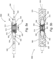
- FIG. 5b illustrates a top, partial cross-section view of one example embodiment of a firearm 550 of the dual-cartridge assembly 500 shown in Fig. 5a .
- Firearm 550 includes a front ("combat") barrel 560 and a rear ("dummy") barrel 570, wherein front barrel 560 and a rear barrel 570 are equal in length.
- Both primary cartridge 520 and secondary cartridge 530 are of the same type, including the same weight and quantity of gunpowder (502, 503).
- the front combat barrel 560 is fixed while the rear barrel 570 is utilized as a hammer is used to transfer the detonation impact energy, as described hereabove.
- the dual barrels firearm 550 has about double the size and double the weight of a compatible single barrel firearm. To overcome the above-mentioned deficiencies of firearm 550, the following improved embodiments are described.
- the bullet (522, 532) in each common cartridge (520, 530) has a rear section and a front section, wherein the rear section of the bullet seals the front end of the casing (524, 534).
- the barrel of the firearm has an inner-barrel-diameter D f
- the rear section of a bullet (522, 532) has an external diameter that is fitted to the inner-barrel-diameter D f of the respective firearm barrel (that is, the rear section of a bullet (522, 532) has an external diameter that is slightly larger than the inner-barrel-diameter D f of the respective firearm barrel to thereby obtain a sealing effect, to maximize the respective thrust force, whereas the bullet is made of a much softer material than the material of the respective barrel).
- the casing (524, 534) of the respective cartridge has an external diameter that is larger than the inner-barrel-diameter Dr.
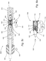
- Fig. 5c illustrates a top, partial cross-section view of one example embodiment of a firearm 600 of the dual-cartridge assembly 500 shown in Fig. 5a , wherein the dual-cartridge assembly 500 is utilized as a first asymmetric dual-cartridge assembly.
- firearm 600 includes a front ("combat") barrel 560 and a rear ("dummy") barrel 570, however, front barrel 660 and a rear barrel 670 are not equal in length.
- Front barrel 660 has a normal length adapted to shoot front bullet 522 forward therethrough at a preconfigured ballistic path.
- Rear barrel 670 is shorter than the length of front bullet 522.
- the primary cartridge 520 is a "combat” cartridge
- the secondary cartridge 630 may be a “combat” cartridge of the same type or just dummy or blank cartridge.
- the difference in thrust forces ⁇ F between the primary and secondary cartridges (520 and 630) is compensated using an additional recoil compensation element - a muzzle-brake 640.
- a recoil compensator such as, with no limitations, a muzzle brake
- muzzle-brake 640 is configured to compensate for the difference in thrust forces ⁇ F , by redirecting some of the primary cartridge propellant gasses.
- Muzzle-brake 640 in conjunction with the recoil force 635 generated by secondary cartridge 630, combine into a force that is equal to the recoil force 525 ( F p ) generated by primary cartridge 520 in direction opposite to primary cartridge recoil F p .
- the advantage of firearm 600 over firearm 550 is having lower firearm length and lower firearm weight, and can use a secondary ammunition unit that is has a lighter weight than the weight of the primary cartridge 520, such as, with no limitations, a dummy secondary cartridge 630.
- a secondary ammunition unit that is has a lighter weight than the weight of the primary cartridge 520, such as, with no limitations, a dummy secondary cartridge 630.
- the disbalance between the primary and secondary cartridges (520 and 630, respectively) gunpowder (502, 503) charges has less effect, since the recoil force 525 of the primary cartridge 520 and the "muzzle brake" thrust force 625 are both generated by the primary cartridge gunpowder 502.
- another recoil reduction element such as a jet nozzle may be placed at end of the rear barrel 670, wherein the rear jet nozzle generates forward thrust from exhaust propellant gasses.
- a recoil compensator such as a muzzle-brake or a jet nozzle may be placed on either the front barrel or the rear barrel, as needed, to compensate for an expected difference in recoil thrust forces ⁇ F .
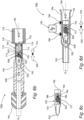
- Fig. 6a illustrates a top, partial cross-section view of a dual-cartridge assembly 700, according to aspects of the present disclosure, wherein the dual-cartridge assembly 700 is utilized as a second asymmetric dual-cartridge assembly, and wherein a disposable secondary cartridge 730 contains an electric ignition circuit.
- Dual-cartridge assembly 700 uses the same principles of active recoil cancelation 500 apparatus, wherein each pair of cartridges includes a primary cartridge 520 and secondary cartridge 730 that are arranged back-to-back inside a dual-cartridge firearm magazine assembly 710 being a recoilless cartridge assembly and wherein primary cartridge 520 is preferably a common, off-the-shelf cartridge.
- the secondary cartridge 730 is an innovative cartridge having an electric, dual-ignition circuit built-in. Secondary cartridge 730 further includes an electronic ignition heater 712 and a firing pin unit 714 that is an integral part of secondary casing 730. Secondary cartridge 730 further includes a sealing unit 732 that can also serve as a counterweight to the weight of primary cartridge 520, in addition to propellant gasses that find their way out.
- a high voltage module 715 turned on the electronic ignition heater 712 to thereby detonate the gunpowder 503 disposed inside secondary casing 730.
- secondary casing 730 is shifted forward and firing pin unit 714 detonates the primer 526 of primary cartridge 520.
- the rest of the chain reaction is similar to that described with respect to firearm 550, wherein secondary casing 730 is ejected in direction 739 out of a rear barrel 770.
- the electronic ignition voltage is transferred, for example, with no limitations, to primary cartridge 520 via two (or more) electrodes (716 and 718) and primary cartridge 520, wherein cartridge assembly 710 is made from a dielectric material.
- dual-cartridge assembly 700 The main advantage of dual-cartridge assembly 700 is that a mechanical hammer firing mechanism is not required, therefore simplifying the feeding mechanism and the synchronization of the ignition process.
- Another advantage of the electronic ignition is that the order in which the cartridges are ignited is known, whereas when the order in which the cartridges are ignited is unknown, the firearm has an unpredictable barrel motion during the fire process (since the physical properties ammunition units are not perfectly repeatable), which may cause growing divergence of the bullets and increase the spread.
- the difference in thrust forces ⁇ F between the primary and secondary cartridges (520 and 730) is compensated using an additional recoil compensation element - a muzzle-brake 740.
- an electrical ignition mechanism is used.
- An example prior art electrical ignition mechanism is a rifle manufactured by Remington: Model 700 EtronX, which uses an electronic primer ignition system.
- Fig. 6c including a cartridge 726 having a bullet 522 and a bullet casing 724 containing a primer 727.
- Fig. 6c further illustrates a counter-weight 792 having an electric arc generation unit 793.
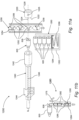
- FIG. 6d schematically illustrates an example firearm 780 that utilizes cartridge and counter-weight sub-system shown in Fig. 6c .
- Firearm 780 includes a front barrel 782 and a rear barrel 784.
- Firearm 780 further includes an electrical ignition mechanism 790 configured to generate a high ignition voltage that is applied via two electrodes (796 and 798), for example to bullet casing 724 and to counter-weight 792, wherein both said bullet casing 724 and said counter-weight 792 are made from conductive materials and separated by an insulator (for example insulator 794).
- insulator 794 has an opening formed at the middle, facing primer 727.
- an electric arc 795 is formed between said counter-weight 792 and said primer 727.
- a conductive protrusion extends from said counter-weight 792 and towards said primer 727.
- the electric arc 795 heats primer 727, to thereby detonate gunpowder 502 inside bullet casing 724.
- casing 730 is shifted forward and firing pin unit 714 detonates the primer 526 of primary cartridge 520.
- the rest of the chain reaction is similar to that described with respect to firearm 550, wherein bullet casing 724, insulator 794 and counter-weight 792 are ejected in direction 739 out of a rear barrel 784.
- At least one or both electrodes (796 and 798) are electrically insulated from the gun barrels (782 and 784).
- recoil-prevention mechanisms using an off-the-shelf cartridge with a single gunpowder charge, wherein the generated gunpowder energy is split between the bullet that is fired through the firearm front barrel, and the bullet/casing that used as counter mass that is fired through the rear of the firearm, without applying a recoil force to the firearm itself.
- the recoil-prevention mechanisms of the present disclosure provide solutions for elimination of recoil energy transfer caused by primer ignition, facilitating usage of standard cartridge while proving recoilless operation including solution for primer ignition and feeding mechanisms.
- Figs. 7 and Fig. 8(a) illustrating a partial cross-section view of a portion of a recoilless firearm 800, showing the principles of a counter-mass mechanism, according to aspects of the present disclosure.
- the counter-mass mechanism of recoilless firearm 800 utilizes a single, standard (off-the-shelf) cartridge 820 that includes a bullet 822 having a rear section 819 and a front section 818, bullet casing 824 wherein rear section 819 of bullet 822 seals the front end of casing 824, gunpowder 802 and primer 826.
- this common sealing method is given by way of example only, with no limitations on other mechanisms and/or methods, known in the art, for sealing a standard cartridge. It should be appreciated that these sealing methods can be used herein within the scope of the present disclosure.
- the barrel of recoilless firearm 800 has an inner-barrel-diameter D f , wherein the rear section 819 of a bullet 822 has an external diameter 821 that is fitted to the inner-barrel-diameter D f of the respective firearm barrel. Furthermore, the casing 824 of the respective cartridge has an external diameter 823 that is larger than the inner-barrel-diameter D f of the respective firearm barrel.
- a cartridge assembly 820 is placed before firing in a fitted cartridge-chamber 862 that is wider than D f , to thereby allow to accommodate cartridge assembly 820, but upon firing, the bullet ejects out of inner-barrel-diameter D f , wherein casing 824 absorbs the recoil force and is thus pushed backward by the formed gases.
- cartridge assembly 820 is not designed for recoilless operation.
- cartridge assembly 820 is configured to be detonated, when a mechanical hammer (not shown) hits the centerfire mechanical primer 826 of cartridge assembly 820, to thereby detonate gunpowder 802 disposed inside bullet casing 824.
- primer 826 ignites, it is almost impossible to prevent the transfer a large portion of the formed recoil energy from the bullet casing 824 back to the hitting hammer of the firearm.
- the barrel of recoilless firearm 800 has a barrel front opening 851 ( D f ) and, according to aspects of the present disclosure, a barrel rear opening 871.
- bullet casing 824 When bullet 822 is fired in the direction (825) of target, through the firearm front opening 851 ( D f ) of recoilless firearm 800, in the direction of target, bullet casing 824 is used as a counterweight to the fired bullet 822, wherein bullet casing 824 is fired in an opposite direction through the rear opening 871 of recoilless firearm 800, whereas energy generated by the detonated gunpowder 802 is split between bullet 822 and bullet casing 824, firing them in opposite direction, without any recoil force effecting the recoilless firearm 800.
- Figs. 8a-8d illustrate a firearm assembly and methodology 900 of using thereof, in a partial cross-section views, an example structure and the firing steps of using an example piped bolt-hammering-unit 930 and a disposable firing pin 910, to bring about detonation and the shooting chain of events involved.
- Firearm assembly and methodology 900 solves the problem formed by the recoil force transfer through hammer using the principles outlined in Fig. 7 .
- a unidirectional energy transfer mechanism 940 transfers a forward thrust 945 to bolt-hammering-unit 930 that thereby moves forward in direction 935.
- piped bolt-hammering-unit 930 moves forward in direction 935, meets firing pin 910 and continuous to move forward until the firing pin 910 pecks primer 826, as shown in the example illustrated in Fig. 8(b) , to thereby ignite primer 826 and thereby detonate gunpowder 802 disposed inside cartridge casing 824 to initiate the firing of bullet 822 in a forward direction 825.
- gunpowder 802 While the explosion of gunpowder 802 generates propellant gasses 925 that, on the one hand push bullet 822 in a forward direction 825, the propellant gasses 925 also push bullet casing 824 in the opposite direction 835.
- unidirectional energy transfer mechanism 940 prevents bolt-hammering-unit 930 from moving back in direction 935.
- bullet casing 824 is pushed back by propellant gasses 925, wherein recoil force are applied to firing pin 910 and bolt-hammering-unit 930.
- both firing pin 910 and bullet casing 824, that absorb the energy of the recoil are flown out through inner opening 932 of bolt-hammering-unit 930 out of the firearm rear.
- Firing pin 910 include a pin 914, a pin-body 912 and wings 916.
- the deformation takes a non-limiting form of the bending of wings 916 of disposable firing pin 910.
- pin-body 912 is predesigned to withstand the recoil force and wings 916 are predesigned to band at a preconfigured location and force.
- a predesigned muzzle-brake 640 can be added to the recoilless firearm, wherein a muzzle-brake 640 is used to cancel the small residual portion of the recoil energy formed during deformation of disposable firing pin 910.
- recoilless operation of a firearm that uses standard ammunition can be achieved by preventing the recoil energy, formed upon detonation of the primer 826, from being transferred back to firearm hammer. According to aspects of the present this is achieved by using a disposable firing pin that is deformed or broken apart by the bursting recoil energy and eject from the firearm, along with the ammunition casing, via a designated escape path, which bypasses the hammer.
- the disposable firing pin may have a variety of shapes and can be operatively coupled to the hammer and/or to the ammunition by any form or method.
- a unidirectional energy transfer mechanism of a bolt-hammering-unit 930 may be embodied in numerous ways and shapes, whereas the piped shape is presented as an example only, with no limitation.
- the objective of a hammer unidirectional energy transfer mechanism is to allow bolt-hammering-unit 930 the to move freely and linearly in a first direction (825), and be blocked when trying to move in the opposite direction (835). Thereby, allowing free motion towards primer 826 and block the return upon the formation of the propellant gasses 925.
- a hammer unidirectional energy transfer mechanism 940 wherein the unidirectional energy transfer mechanism is securely coupled with the bolt-hammering-unit 930.
- a ratchet-based or motion limitation mechanisms are used, wherein a motion limitation mechanism is locked after the ammunition, such as cartridge assembly 820, is fitted into inner opening 932 of bolt-hammering-unit 930 and limits the bolt-hammer-unit 930 backward motion, and wherein a ratchet-based mechanism allows only unidirectional linear motion while preventing motion of the moving part in the opposite direction.
- any motion limitation mechanism known in art as a "breechblock locking mechanism", for example, a breech locking mechanism shown in https://en.wikipedia.org/wiki/Rotating_bolt, can be used as a unidirectional linear motion to block rearward motion of the bolt-hammer-unit 930, while in a cocked state.
- Fig. 9 illustrating a partial cross-section view of a portion of a recoilless firearm 950, showing the principles of a counter-mass mechanism, according to other aspects of the present disclosure.
- the counter-mass mechanism of recoilless firearm 950 utilizes a single, standard (off-the-shelf) cartridge 820 that includes a bullet 822, a bullet casing 824 wherein the rear section of bullet seals the front end of casing 824, gunpowder and a primer 826.
- this common sealing method is given by way of example only, with no limitations on other mechanisms and/or methods, known in the art, for sealing a standard cartridge. It should be appreciated that these sealing methods can be used herein within the scope of the present disclosure.
- the front barrel 850 of recoilless firearm 950 has an inner-barrel-diameter D f , wherein the casing 824 of the respective cartridge has an external diameter 823 that is larger than the inner-barrel-diameter D f of the respective firearm barrel.
- a cartridge assembly 820 is placed before firing in a fitted cartridge-chamber that is wider than D f , to thereby allow to accommodate cartridge assembly 820, but upon firing, the bullet ejects out of inner-barrel-diameter D f , wherein casing 824 absorbs the recoil force and is thus pushed backward by the formed gases.
- recoilless firearm apparatus 950 utilizes another counter-mass mechanism 960, according to aspects of the present disclosure, such that a recoil effect can be prevented.
- Counter-mass mechanism 960 being another embodiment of a disposable firing-pin, includes a frontal-body-section 962 having a pin-front-end, being an open end, wherein a pin 964 is disposed at the pin-front-end.
- Counter-mass mechanism 960 further includes a rear-body-section 966 having a pin-rear-end with a larger diameter end 968, wherein the larger diameter of said pin-rear-end is configured to seal the rear discharge opening (similar to the rear opening 871 of recoilless firearm 800) of front barrel 850.
- the firing pin is made of rigid materials, while at least the rear-body-section 966, including the larger diameter end, is made of deformable or breakable materials, such that when applying an excess force F e onto firing pin 964, the Counter-mass mechanism 960 deforms or breaks.
- a first ratchet-based mechanism is used.
- Fig. 10a illustrates a unidirectional energy transfer mechanism 1000, according to aspects of the present disclosure.
- Unidirectional energy transfer mechanism 1000 includes a linear moving part 1010 having one or more saw teeth 1014 and a pivotal leaping-arm 1020 configured to pivot about axis 1025.
- a second ratchet-based mechanism is used.
- Figs. 10b and 10c illustrate another example unidirectional energy transfer mechanism 1100, according to some other embodiments of the present disclosure.
- Unidirectional energy transfer mechanism 1100 includes a linear moving slider 1110, being the moving part, a motion control element 1112 having one or more saw teeth 1112 and a moving ball 1120, disposed between the generally vertical side 1116 of a first tooth 1112 and the sloped side 1114 of a second tooth 1112, wherein moving ball 1120 is securely interconnected to the vertical side 1116 of the first tooth 1112 by a biasing element such as, with no limitation, a spring 1130.
- a biasing element such as, with no limitation, a spring 1130.
- biasing element 1130 maintains moving rotating (in direction 1125) ball 1120 free such that linear moving slider 1110 can move freely.
- biasing element 1130 pushes moving rotating (in direction 1126) ball 1120 and thereby moving ball 1120 climbs over the sloped side 1114 of a second tooth 1112 such that moving ball 1120 gets stuck between the sloped side 1114 of a second tooth 1112 and the bottom of linear moving slider 1110, to thereby block linear moving slider 1110 from moving further in direction 1136.
- Firearm system 1200 includes a barrel 1240 having a cartridge-chamber 1242, at least one disposable firing pin 1252 and a piped bolt-hammering-unit 1220 (similar to piped bolt-hammering-unit 930).
- each firing pin 1252 includes at least two wings 1256 (similar to wings 916), a pin (not shown) similar to pin 914 and a pin-body 1254 (similar to pin-body 912).
- grooves 1224 are formed, each configured to accommodate a respective wing 1256 of firing pin 1252.
- firearm system 1200 further includes a cartridge magazine 1260, adapted to hold cartridges 820, for automatic and semi-automatic firearms.
- cartridge magazine 1260 adapted to hold cartridges 820, for automatic and semi-automatic firearms.
- respective multiple disposable firing pins 1252 may be supplied via a separate, continuous band magazine 1250 having multiple disposable firing pins 1252.
- a unidirectional energy transfer mechanism transfers a forward thrust to piped bolt-hammering-unit 1220 that thereby moves forward in direction 1225, according to the methodology described with respect to firearm assembly and methodology 900.
- a respective firing pin 1252 is dispatched from band magazine 1250, wherein wing 1256 of firing pin 1252 are sat inside respective grooves 1224 of piped bolt-hammering-unit 1220, while piped bolt-hammering-unit 1220 moves forward through band magazine 1250, until the pin of disposable firing pin 1252 pecks primer 826 of cartridge assembly 820, and the firing sequence begins, including the bending of wings 1256 of firing pin 1252 and including both firing pin 1252 and bullet casing 824, that absorb the energy of the recoil are flown out through the inner opening of piped bolt-hammering-unit 1220, out of the rear of firearm system 1200.
- hammer unidirectional energy transfer mechanisms will now be described. According to aspects of the present disclosure, there are provided example embodiments of a unidirectional energy transfer mechanism 940, wherein a bolt-and-hammer mechanism are used.
- the disposable firing pin may come in the form of being detachably embedded in an elongated band magazine, wherein a single firing pin is torn off from the band in each shot.
- An example of such embodiment is detailed with respect to band magazine 1250, described hereabove.
- the disposable firing pin may also come in the form of being detachably mounted on an elongated stick of firing pin, wherein a single firing pin is torn off from the stick in each shot.
- the stick may be straight, arched or in a circled form.
- Fig. 11b a stick magazine 1280.
- Stick magazine 1280 includes rigid segments of firing pin 1282, that are interconnected by a breakable element 1285.
- the end of the stick serves as the pecker that pecks the primer 826.
- the wire stick then moves up whereas the next in line firing pin segment 1282 becomes the first in line firing pin segment 1282.
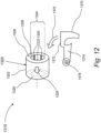
- Fig. 12 illustrates a unidirectional energy transfer mechanism 1310, according to aspects of the present disclosure.
- Unidirectional energy transfer mechanism 1310 includes a ribbed bolt-hammering-unit 1320 and a hammer 1370.
- Piped bolt-hammering-unit 1320 being the bolt, has an opening 1324 formed there at the center, and one or more directing ribs 1330 placed at preconfigured locations of the inner wall 1326 of opening 1324.
- Hammer 1370 includes a pivotal arm 1374 configured to pivot about axis 1378, and a hitting face 1372. When hammer 1370 is activated, it pivots forcefully in direction 1375, wherein upon hitting face 1372 impacting a proximal end face 1328 of ribbed bolt-hammering-unit 1320, ribbed bolt-hammering-unit 1320 moves linearly forward with respect to the respective firearm, in direction 1325.
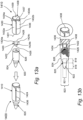
- recoilless-cartridge-assembly 1400 as illustrated in Fig. 13a in an exploded view.
- Fig. 13b is a cross-section view of recoilless-cartridge-assembly 1400.
- Recoilless-cartridge-assembly 1400 includes a standard cartridge, such as cartridge 520/820, and a detonation assembly add-on 1410, adapted to fit onto standard cartridge 820.
- Detonation assembly 1410 includes a cylindrical-envelope 1430 having an inner diameter, an external diameter, a front end 1431 and a rear end 1434, wherein the front end 1431 operatively faces the barrel of the hosting firearm.
- the cylindrical-envelope 1430 is enclosed at the rear end side by a cylindrical rear plug, having a cup shape.
- Cylindrical cup rear plug 1438 includes an enclosed cylindrical wall 1437 enclosed at the rear end by plug-wall 1439, wherein cylindrical-envelope 1430 is securely attached onto the external surface of cylindrical wall 1437. It should be noted that detonation assembly 1410 can be made of a single unit.
- Detonation assembly 1410 further includes a disposable firing pin 1420 that is similar to disposable firing pin 910.
- Disposable firing pin 1420 includes a pin 1426, a pin-body 1422 and at least one wing 1424, having a wing-span diameter 1428.
- firing pin 1420 When operatively assembled, firing pin 1420 is inserted into cylindrical-envelope 1430 via front end 1431, wherein pin 1426 faces the barrel of the hosting firearm.
- the peripheral wing-span diameter of the ends of the at least one wing 1424 is purposely larger than the internal diameter of cylindrical-envelope 1430 and is smaller than external diameter of cylindrical-envelope 1430.
- a fitted through slit 1436 is formed, for each respective wing 1424, in cylindrical-envelope 1430, extending from front end 1431 to rear end 1434.
- each slit 1436 accommodates a respective wing 1424, such that the open end of each wing 1424 sticking out of the slit 1436, as illustrated in Fig. 13b .
- the inner diameter of rear end 1434 of cylindrical-envelope 1430 is enclosed by a rear plug 1438, to which inner surface of cylindrical-envelope 1430 rear plug 1438 is securely attached.
- slits 1436 segment cylindrical-envelope 1430 into separate peripheral segments 1432, wherein the number of slits 1436, the number of wings 1424, and the number of peripheral segments 1432 is equal.
- the of slits 1436 may be twice the number of wings 1424.
- the rear end 1434 of each peripheral segment 1432 is sloped, starting at a first corner of the rear end 1434 of the peripheral segment 1432 (and proximal to the rear end of rear plug 1438), ending at the other corner of the rear end 1434 of that peripheral segment 1432, formed by the next slit, and at a predesigned distance from the rear end of rear plug 1438.
- detonation assembly 1400 embraces bullet casing 824 of cartridge 820.
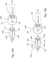
- Fig. 14a illustrating a ribbed bolt-hammering-unit 1320 moving linearly forward with respect to the respective firearm, in direction 1325, towards recoilless-cartridge-assembly 1400.
- the diameter of opening 1324 of ribbed bolt-hammering-unit 1320 is fittingly larger than the external diameter of cylindrical-envelope 1430.
- directing ribs 1330 meet the sloped rear ends 1434 of the respective peripheral segment 1432, causing detonation assembly 1410 (or optionally, the whole of recoilless-cartridge-assembly 1400) to pivot until each of the directing ribs 1330 meet the respective slit 1436, and continues to move forward until meeting the end of the respective wing 1424.
- recoilless-cartridge-assembly 1400 is in position at the cartridge-chamber of a firearm, firing pin 1420 is pushed forward to thereby, when pin 1426 pecks primer 826 of cartridge assembly 820, and the firing and detonation sequences begin.
- relative pivotal motion between the ribbed bolt-hammering-unit 1320 and the detonation assembly 1410 can be performed by the recoilless cartridge-assembly 1400, the ribbed bolt-hammering-unit 1320 or a combination thereof.
- each sloped rear end 1434 of a respective peripheral segment 1432 can be replaced by two slopes, each configured to create a pivotal motion of detonation assembly 1410 in opposite pivotal direction and shortening the pivotal step.
- Recoilless-cartridge-assembly 1450 includes a standard cartridge, such as cartridge 520/820, and a detonation assembly add-on 1450, adapted to fit onto standard cartridge 820.
- detonation assembly 1450 is similar to detonation assembly 1400, except for the rear end 1484 of each peripheral segment 1482, that correspond the rear end 1434 of each peripheral segment 1432, respectively. While the sloped rear end of each peripheral segment 1432 leads towards a single slit 1436, each peripheral segment 1482 has two sloped ends 1484a and 1484b, wherein each sloped end 1484 leads towards a neighboring slit 1436. Therefore, in this case, the number of sloped ends 1484 is twice the number of slit 1436.
- Fig. 15a illustrates a blow-forward type firearm 1300 that includes a barrel unit 1340 and a bolt assembly 1390, according to aspects of the present disclosure.
- Bolt assembly 1390 includes a ribbed bolt-hammering-unit 1320 as described hereabove, wherein ribbed bolt-hammering-unit 1320, is configured to facilitate the pecking by firing pin 1426 of the primer 826 of cartridge assembly 820, and thereby initiate the firing and detonation sequences, as described here above.
- Bolt assembly 1390 is coupled to operate with a barrel unit 1340 using another example usage of a unidirectional energy transfer mechanism, according to aspects of the present disclosure.
- Firearm 1300 is configured to fire bullet 822 of a recoilless-cartridge-assembly 1400, as described here above.
- firearm 1300 is configured to activate the firing sequence when moving the barrel unit 1340 of firearm 1300 backwards, in direction 1335.
- a biasing element such as a spring
- Bolt assembly 1390 further includes a piped limiter 1392 that is engaged to move linearly with respect to barrel unit 1340, upon a bearing mechanism 1398. Situated at a forward section of piped limiter 1392. Piped limiter 1392 is configured to allow insertion of a recoilless-cartridge-assembly 1400 into the cartridge-chamber of firearm 1300. Piped limiter 1392 is further configured to accommodate ribbed bolt-hammering-unit 1320. Piped limiter 1392 further includes, at the rear end of piped limiter 1392, bolt-stoppers 1394, preventing ribbed bolt-hammering-unit 1320 from escaping piped limiter 1392, when moving backwards.
- bearing mechanism 1398 allows free linear motion of piped limiter 1392 with respect to barrel unit 1340 .
- recoilless-cartridge-assembly 1400 meets ribbed bolt-hammering-unit 1320, wherein barrel unit 1340, recoilless-cartridge-assembly 1400 and ribbed bolt-hammering-unit 1320 continue to move backwards until ribbed bolt-hammering-unit 1320 is stopped by bolt-stoppers 1394.
- directing ribs 1330 meet the sloped rear ends 1434 of the respective peripheral segment 1432, causing recoilless-cartridge-assembly 1400 to pivot until each of the directing ribs 1330 meet and enter the respective slit 1436, and recoilless-cartridge-assembly 1400 continues to move backwards until meeting the end of the respective wing 1424.
- recoilless-cartridge-assembly 1400 continues to move backwards, however, the ends of the wing 1424 remain stuck at the front-end-face 1329 (see Fig. 12 ) of ribbed bolt-hammering-unit 1320. Therefore, primer 826 of cartridge assembly 820 continuous to move towards firing pin 1420 until pin 1426 pecks primer 826, as illustrated in a partial cross section view of Fig. 15b , and the firing and detonation (828) sequences begin.
- the propellant gasses formed at the detonation (828) also push cartridge casing 824 in direction 1335, along with detonation assembly 1410.
- the ends of wings 1424 are deformed or broken, and cartridge casing 824, firing pin 1420 and detonation assembly 1410 proceed to move backwards, wherein slit 1436 slide over the respective directing ribs 1330 and then through opening 1324 (see Fig. 14 ) of ribbed bolt-hammering-unit 1320, until completely ejecting out of firearm 1300.
- motion limiters including linear motion limiters and rotational motion limiters may take a variety of forms, as known in the art.
- FIG. 15c illustrates a blow-forward type firearm 1301 that includes a barrel unit 1340 and a bolt assembly 1391, according to other aspects of the present disclosure.
- Firearm 1301 is quite similar to firearm 1300, except that when moving the barrel unit 1340 of firearm 1300 backwards, firearm 1300 goes to a cocked state, while the recoilless cartridge assembly 1400 and the ribbed bolt-hammering unit 1320 rotate one with respect to the other, until reaching a cocked position and ready to be fired. Then, an additional mechanism 1310, as described with respect to Fig. 12 , is activated to provide ribbed bolt-hammering-unit 1320 with a forward thrust by a hammer 1370.
- piped limiter 1392 is adapted to allow hammer 1370 to hit ribbed bolt-hammering-unit 1320.
- bolt assembly 1390 further includes barrel stopper 1396 to block barrel unit 1340 from impacting pin 1426 of firing pin 1420, while moving backwards.
- Firearm system 1500 includes a barrel 1540 having an inner-barrel-diameter and a cartridge-chamber 1542, at least one recoilless-cartridge-assembly 1400 and a piped bolt-hammering-unit 1320.
- firearm system 1500 further includes a magazine 1560, adapted to hold a number of recoilless-cartridge-assemblies 1400, for automatic and semi-automatic firearms.
- firearm system 1500 can further include a ribbed bolt-hammering unit 1320 that is used as a part of the feeding mechanism that operatively interacts with magazine 1560. Ribbed bolt-hammering unit 1320 extracts a recoilless-cartridge-assembly 1400, that is next in line, from magazine 1560 and loads the extracted recoilless-cartridge-assembly 1400 into cartridge-chamber 1542 of barrel 1540.
- the ribbed bolt-hammering-unit 1320 continues to move forward towards recoilless-cartridge-assembly 1400, and thereby directing ribs 1330 meet the sloped rear ends 1434 of the respective peripheral segment 1432, causing recoilless-cartridge-assembly 1400 to pivot until each of the directing ribs 1330 meet and enter the respective slit 1436, and then continue and meet the ends of wing 1424, via the front-end-face 1329 of ribbed bolt-hammering-unit 1320.
- ribbed bolt-hammering-unit 1320 continuous the move forward, pushing firing pin 1420 forward towards primer 826 of cartridge assembly 820, until reaching their cocked position within predefined safety distance of the firing pin 1420 from the primer 826, resting in the cocked position, being in a cocked state, ready to be fired.
- a hammer mechanism for example mechanism 1370 hammers the rear face 1328 of ribbed bolt-hammering-unit 1320 that thereby moves forward, to direction 1325, according to the methodology described with respect to methodology 1310 (see Fig. 12 ).
- the hammering energy is then transferred to firing pin 1420,wherein the tip of firing pin 1426 pecks the primer 826 of cartridge assembly 820, and the firing sequence begins, including the bending of wings 1424 of firing pin 1420 and including both firing pin 1420 and bullet casing 824, that absorb the energy of the recoil are flown out through the inner opening 1324 of ribbed bolt-hammering-unit 1320, out of the rear of firearm system 1500.
- the difference in these forces ⁇ F is compensated using an additional recoil compensation element - a muzzle-brake 1244, 1344, and 1544, respectively.
- pin-wing(s) can be predesigned by selecting preconfigured materials for the various parts of the respective firing-pin.
- F e excess force
Landscapes
- Engineering & Computer Science (AREA)
- General Engineering & Computer Science (AREA)
- Chemical & Material Sciences (AREA)
- Combustion & Propulsion (AREA)
- Aviation & Aerospace Engineering (AREA)
- Toys (AREA)
- Portable Nailing Machines And Staplers (AREA)
- Operating, Guiding And Securing Of Roll- Type Closing Members (AREA)
Claims (15)
- Rückstoßfreie Schusswaffenvorrichtung zum Abfeuern mindestens eines Geschosses einer jeweiligen Standardpatrone mit einem Standardkaliber, umfassend:a) einen vorderen Lauf (782) mit einem inneren Laufdurchmesser und einer hinteren Patronenkammer mit einem hinteren Patronenkammerdurchmesser, die dazu ausgelegt ist, die Standardpatrone aufzunehmen;b) einen Einweg-Auslöseaktivator; undc) eine hintere Auswurföffnung, die hinter dem vorderen Lauf ausgebildet und auf die Längsachse des vorderen Laufs ausgerichtet ist;wobei die Standardpatrone ferner eine Hülse (724) mit einem Außendurchmesser aufweist, der kleiner als der hintere Patronenkammerdurchmesser ist, wobei die Hülse einen abgedichteten Hülseninnenraum umschließt, der Schießpulver (502) enthält, und wobei die Hülse einen Zünder (727) aufweist; undwobei beim Aktivieren des Zünders der Zünder explodiert, um dadurch das Schießpulver zu zünden, wodurch Treibgase innerhalb der Patrone entstehen, die wie folgt sowohl nach vorne als auch nach hinten gerichtet sind:a) nach vorne: Abfeuern des Geschosses über den vorderen Lauf; undb) nach hinten: Schieben der Hülse, die ein Gegengewicht zu dem Geschoss darstellt, durch eine Rückstoßkraft Fp, um dadurch die Hülse über die hintere Auswurföffnung aus der Schusswaffenvorrichtung auszustoßen.
- Rückstoßfreie Schusswaffenvorrichtung nach Anspruch 1, wobei der Einweg-Auslöseaktivator ein elektrischer Kontakt ist, der dazu ausgelegt ist, elektrische Energie von einer seitlich angeordneten Elektrode zu dem Zünder zu übertragen, um dadurch den Zünder zu aktivieren, und wobei der Einweg-Auslöseaktivator zusammen mit der Hülse aus der Schusswaffenvorrichtung über die hintere Auswurföffnung ausgestoßen wird.
- Rückstoßfreie Schusswaffenvorrichtung nach Anspruch 1, wobei der Einweg-Auslöseaktivator ein Schlagbolzen ist, wobei die Aktivierung des Zünders durch den Schlagbolzen erfolgt, der den Zünder trifft, und wobei der Einweg-Schlagbolzen zusammen mit der Hülse aus der Schusswaffenvorrichtung über die hintere Auswurföffnung ausgestoßen wird.
- Rückstoßfreie Schusswaffenvorrichtung nach Anspruch 3, wobei der Einweg-Schlagbolzen Folgendes umfasst:a) einen Bolzenkörper mit einem Körper, der ein vorderes Bolzenende hat, das ein offenes Ende ist, und einem hinteren Bolzenende;b) einen Bolzen, der an dem vorderen Bolzenende angeordnet ist; undc) mindestens einen Bolzenflügel, der an dem hinteren Bolzenende angeordnet ist,wobei, wenn sich die Vorrichtung im gespannten Zustand befindet, das hintere Ende der Standardpatrone in der Patronenkammer sitzt und der Bolzen in sicherer Nähe zum Zünder positioniert ist;wobei der Schlagbolzen aus starren Materialien hergestellt ist; undwobei die Teile des Schlagbolzens, einschließlich mindestens eines Bolzenflügels, aus verformbaren oder bruchfähigen Materialien bestehen, sodass, wenn eine übermäßige Kraft Fe auf mindestens einen Bolzenflügel ausgeübt wird, mindestens ein Bolzenflügel sich verformt oder bricht; oderwobei der Einweg-Schlagbolzen Folgendes umfasst:a) einen Bolzenkörper mit einem Körper, der ein vorderes Bolzenende, das ein offenes Ende ist, einen vorderen Körperabschnitt und einen hinteren Körperabschnitt mit einem hinteren Bolzenende hat, das ein größeres Durchmesserende hat; undb) einen Bolzen, der an dem vorderen Bolzenende angeordnet ist,wobei das größere Durchmesserende des hinteren Bolzenendes dazu ausgelegt ist, die hintere Auswurföffnung zu verschließen;wobei, wenn sich die Vorrichtung im gespannten Zustand befindet, das hintere Ende der Standardpatrone in der Patronenkammer sitzt und der Bolzen in sicherer Nähe zum Zünder positioniert ist;wobei der Schlagbolzen aus starren Materialien hergestellt ist; undwobei mindestens der hintere Körperabschnitt, einschließlich des größeren Durchmesserendes, aus verformbaren oder bruchfähigen Materialien besteht, sodass, wenn eine übermäßige Kraft Fe auf den Schlagbolzen ausgeübt wird, der Schlagbolzen sich verformt oder bricht.
- Rückstoßfreie Schusswaffenvorrichtung nach Anspruch 4, ferner umfassend eine rohrförmige Bolzenschlageinheit mit einer Bolzenvorderseite und einer Bolzenrückseite, und umfassend einen Körper mit einer darin ausgebildeten Bolzeninnenöffnung,wobei die Bolzeninnenöffnung größer als der Außendurchmesser der Hülse ist, wodurch eine freie Längsbewegung der Hülse darin ermöglicht wird;wobei die Bolzenflügel eine Flügelspanne haben, die größer als die Bolzeninnenöffnung ist;wobei, wenn sich die Schusswaffe im gespannten Zustand befindet, die Bolzenvorderseite in sicherer Nähe zu den Bolzenflügeln positioniert ist; undwobei die Aktivierung des Zünders durch Ausüben einer unidirektionalen Vorwärtskraft auf die rohrförmige Bolzenschlageinheit erfolgt, die den Einweg-Schlagbolzen nach vorne drückt und dadurch der Bolzen den Zünder aktiviert.
- Rückstoßfreie Schusswaffenvorrichtung nach einem der Ansprüche 1-5, ferner umfassend einen Rückstoßverhinderungsmechanismus, wobei der Rückstoßverhinderungsmechanismus Folgendes umfasst:a) einen hinteren Lauf mit der hinteren Auswurföffnung; undb) ein Doppelpatronen-Schusswaffenmagazin, das dazu ausgelegt ist, die Standardpatrone und ein Gegengewicht mit einem Zünderaktivator aufzunehmen,wobei die Standardpatrone und das Gegengewicht in einer Rücken-an-Rücken-Konfiguration angeordnet sind;wobei der Zünderaktivator betriebsfähig zwischen dem Zünder der Primärpatrone und dem Gegengewicht platziert ist, sodass der Zünderaktivator mit dem Zünder der Primärpatrone ausgerichtet ist;wobei das Geschoss der Primärpatrone dazu ausgelegt ist, über den vorderen Lauf abgefeuert zu werden, und die Hülse und das Gegengewicht dazu ausgelegt sind, über den hinteren Lauf abgefeuert zu werden; undwobei bei der Zündung der Primärpatrone die erzeugte Rückstoßkraft die Hülse und das Gegengewicht nach hinten drückt, um dadurch die Hülse und das Gegengewicht über die hintere Auswurföffnung aus der Schusswaffenvorrichtung auszustoßen.
- Schwebendes Schusswaffensystem, umfassend:a) ein schwebendes Teilsystem, das dazu ausgelegt ist, eine rückstoßfreie Schusswaffenvorrichtung nach einem der Ansprüche 1-6 in die Luft zu heben und zu einem festgelegten Ziel zu fliegen; undb) eine Montageplattform,wobei die rückstoßfreie Schusswaffe sicher an der Montageplattform befestigt ist; undwobei beim Abfeuern mindestens eines Geschosses die verbleibende Restrückstoßkraft es dem schwebenden Schusswaffensystem ermöglicht, einen kontrollierten Flug fortzusetzen.
- Schwebendes Schusswaffensystem nach Anspruch 7, wobei die Plattform einen ersten Kardanrahmen mit einer Tragfläche umfasst, und wobei die rückstoßfreie Schusswaffenvorrichtung an dem ersten Kardanrahmen montiert ist.
- Schwebendes Schusswaffensystem nach Anspruch 7, ferner umfassend ein elektrooptisches Modul mit einer Kamera, wobei die Kamera eine optische Sichtlinie aufweist, die auf das Ziel gerichtet ist.
- Schwebendes Schusswaffensystem nach Anspruch 9, wobei das elektrooptische Modul an dem ersten Kardanrahmen angebracht ist; oderwobei das schwebende Schusswaffensystem ferner einen zweiten Kardanrahmen umfasst, wobei das elektrooptische Modul an dem zweiten Kardanrahmen angebracht ist,vorzugsweise wobei der zweite Kardanrahmen unabhängig von dem ersten Kardanrahmen ist oder wobei der zweite Kardanrahmen auf dem ersten Kardanrahmen montiert ist.
- Schwebendes Schusswaffensystem nach einem der Ansprüche 9-10, wobei die optische Sichtlinie kontrollierbar mit der rückstoßfreien Schusswaffe ausgerichtet ist, um dadurch sequentielle Schüsse auf das Ziel zu ermöglichen, ohne die Visierlinie zu verlieren, vorzugsweise wobei das Ausrichten der optischen Sichtlinie-Visierlinie (Boresighting) entweder eine mechanische Ausrichtung oder ein elektronisches Boresighting unter Verwendung einer Verschiebung oder einer Bildkreuzbewegung ist, insbesondere wobei das Boresighting das Verriegeln der Sichtlinie auf dem Ziel und das steuerbare Ausrichten der Längsachse des vorderen Laufs mit der optischen Sichtlinie der Kamera umfasst, oder
wobei das Boresighting in Echtzeit unter Verwendung ballistischer Berechnungen, Windvektorberechnungen oder einer Kombination davon aktualisiert wird. - Rückstoßfreie Schusswaffenvorrichtung zum bidirektionalen rückstoßfreien Abfeuern mindestens eines Geschosses einer jeweiligen Standardpatrone mit einem Standardkaliber, umfassend:a) einen vorderen Lauf mit einem inneren Laufdurchmesser und einer hinteren Patronenkammer mit einem hinteren Patronenkammerdurchmesser, die dazu ausgelegt ist, die Standardpatrone aufzunehmen;b) einen Einweg-Auslöseaktivator;c) einen Rückstoßverhinderungsmechanismus, umfassend:i. einen hinteren Lauf mit der hinteren Auswurföffnung; undii. ein Doppelpatronen-Schusswaffenmagazin, das dazu ausgelegt ist, die Standardpatrone aufzunehmen, die eine Primärpatrone (520), eine Sekundärpatrone (530) und eine Doppelschlagbolzeneinheit (514) mit einem Primärbolzen und einem Sekundärbolzen ist, wobei die Sekundärpatrone eine sekundäre versiegelte Hülse beinhaltet, die Folgendes beinhaltet:A. Schießpulver (503); undB. einen Sekundärzünder (536),wobei die Primärpatrone und die Sekundärpatrone in einer Rücken-an-Rücken-Konfiguration angeordnet sind;wobei die Doppelschlagbolzeneinheit betriebsfähig zwischen dem Zünder der Primärpatrone und dem Sekundärzünder platziert ist, sodass der Primärbolzen mit dem Zünder der Primärpatrone ausgerichtet ist und der Sekundärbolzen mit dem Sekundärzünder ausgerichtet ist; wobei das Geschoss der Primärpatrone dazu ausgelegt ist, über den vorderen Lauf abgefeuert zu werden, und die Sekundärpatrone dazu ausgelegt ist, über den hinteren Lauf abgefeuert zu werden; undwobei bei gleichzeitiger Zündung der Primärpatrone und der Sekundärpatrone die durch die Sekundärpatrone erzeugte Rückstoßkraft die durch die Primärpatrone erzeugte Rückstoßkraft aufhebt.
- Rückstoßfreie Schusswaffenvorrichtung nach Anspruch 12,wobei die Primärpatrone und die Sekundärpatrone vom gleichen Typ sind;wobei der vordere Lauf und der hintere Lauf nicht gleich lang sind; undwobei bei gleichzeitiger Zündung der Primärpatrone die durch die Sekundärpatrone erzeugte Rückstoßkraft die durch die Primärpatrone erzeugte Rückstoßkraft aufhebt; oderwobei die Primärpatrone und die Sekundärpatrone nicht vom gleichen Typ sind;wobei der vordere Lauf und der hintere Lauf nicht gleich lang sind;wobei bei gleichzeitiger Zündung der Primärpatrone die durch die Sekundärpatrone erzeugte Rückstoßkraft die durch die Primärpatrone erzeugte Rückstoßkraft aufhebt; undwobei der Rückstoßverhinderungsmechanismus ferner einen Rückstoßkompensator umfasst, um dadurch Ungleichheiten zwischen den durch die Primärpatrone und die Sekundärpatrone erzeugten Rückstoßkräften auszugleichen.
- Rückstoßfreie Patronenanordnung, umfassend:a) eine Standardpatrone; undb) eine Detonationsanordnung (1410), umfassend:i. eine zylindrische Hülle (1430) mit einem Innendurchmesser, einem Außendurchmesser, einem vorderen Ende und einem hinteren Ende, wobei das vordere Ende betriebsfähig einem vorderen Lauf zugewandt ist;ii. einen hinteren Stopfen (1438), wobei der hintere Stopfen den Innendurchmesser des hinteren Endes der zylindrischen Hülle sicher umschließt; undiii. einen Einweg-Schlagbolzen (1420), umfassend:A. einen Bolzenkörper (1422);B. mindestens einen Flügel (1424) mit einem Flügelspannendurchmesser, wobei der Flügelspannendurchmesser größer als der Innendurchmesser der zylindrischen Hülle ist; undC. einen Bolzen (1426),wobei mindestens ein Durchgangsschlitz (1436) in der zylindrischen Hülle ausgebildet ist, wobei ein Schlitz für jeden jeweiligen Flügel ausgebildet ist;wobei sich jeder Schlitz von dem vorderen Ende der zylindrischen Hülle zu dem hinteren Ende der zylindrischen Hülle erstreckt; undwobei die Schlitze die zylindrische Hülle in separate Umfangssegmente segmentieren.
- Rückstoßfreie Patronenanordnung nach Anspruch 14,wobei das hintere Ende jedes Umfangssegments abgeschrägt ist, beginnend an einer ersten hinteren Ecke jedes Umfangssegments und endend an der anderen Ecke dieses Umfangssegments in einem vorbestimmten Abstand vom hinteren Ende des hinteren Stopfens, und wobei diese Ecke durch das abgeschrägte Umfangssegment und eine Flanke des jeweiligen Schlitzes gebildet wird;wobei, wenn die Zündanordnung betriebsfähig zusammengebaut ist, jeder Schlitz das offene Ende eines jeweiligen Flügels aufnimmt; undwobei, wenn die rückstoßfreie Patronenanordnung betriebsfähig zusammengebaut ist, die Detonationsanordnung die Primärhülse der Primärpatroneneinheit umschließt,vorzugsweise wobei das hintere Ende jedes abgeschrägten Umfangssegments zwei Schrägen aufweist, die jeweils zu einem angrenzenden Schlitz führen.
Applications Claiming Priority (2)
| Application Number | Priority Date | Filing Date | Title |
|---|---|---|---|
| IL271579A IL271579A (en) | 2019-12-19 | 2019-12-19 | Hovering firearm system for drones and methods of use thereof |
| PCT/IL2020/051306 WO2021124337A1 (en) | 2019-12-19 | 2020-12-18 | Hovering firearm system for drones and methods of use thereof |
Publications (3)
| Publication Number | Publication Date |
|---|---|
| EP4078068A1 EP4078068A1 (de) | 2022-10-26 |
| EP4078068A4 EP4078068A4 (de) | 2024-01-17 |
| EP4078068B1 true EP4078068B1 (de) | 2025-04-02 |
Family
ID=76477153
Family Applications (1)
| Application Number | Title | Priority Date | Filing Date |
|---|---|---|---|
| EP20901085.9A Active EP4078068B1 (de) | 2019-12-19 | 2020-12-18 | Schwebendes schusswaffensystem für drohnen und verfahren zur verwendung davon |
Country Status (4)
| Country | Link |
|---|---|
| US (1) | US20220373277A1 (de) |
| EP (1) | EP4078068B1 (de) |
| IL (2) | IL271579A (de) |
| WO (1) | WO2021124337A1 (de) |
Families Citing this family (8)
| Publication number | Priority date | Publication date | Assignee | Title |
|---|---|---|---|---|
| IL277712B2 (en) * | 2020-09-29 | 2024-06-01 | Rafael Advanced Defense Systems Ltd | Armed aerial platform |
| US11703291B2 (en) * | 2020-10-21 | 2023-07-18 | Zhisong Huang | Recoilless automatic firearm |
| CZ309344B6 (cs) * | 2021-09-20 | 2022-09-07 | Helia Miroslava | Palná zbraň s tlumicím zařízením |
| EP4235079B1 (de) * | 2022-02-25 | 2025-08-13 | Huang Zhisong | Rückstossfreie vorrichtung für schusswaffen |
| CN116378849B (zh) * | 2023-02-20 | 2026-02-24 | 航天科工仿真技术有限责任公司 | 一种无人机后坐力控制方法、装置及无人机 |
| KR102734468B1 (ko) * | 2023-12-05 | 2024-11-26 | 국방과학연구소 | 소형 드론 |
| CN117804278A (zh) * | 2024-01-19 | 2024-04-02 | 南京理工大学 | 一种巡飞枪系统及其弹道修正策略 |
| KR102776413B1 (ko) * | 2024-06-28 | 2025-03-07 | 국방과학연구소 | Cta형 멀티콥터 드론 및 멀티콥터 드론 시스템 |
Family Cites Families (14)
| Publication number | Priority date | Publication date | Assignee | Title |
|---|---|---|---|---|
| GB130237A (en) * | 1918-11-05 | 1919-07-31 | Lawrence York Spear | Improvements in Fixed Ammunition for Non-recoil Guns. |
| DE2140875A1 (de) * | 1971-08-14 | 1973-02-22 | Messerschmitt Boelkow Blohm | Vorrichtung zum rueckstoss- und knallfreien abschiessen von geschossen |
| FR2531203B1 (fr) * | 1982-07-30 | 1986-11-14 | Thomson Brandt | Masse de reaction expulsable et arme de tir sans recul incluant une telle masse |
| ES1040269Y (es) * | 1998-05-25 | 1999-07-16 | Mencia Almansa Cesar | Dispositivo antirretroceso perfeccionado aplicable en armas de fuego. |
| CA2290025C (en) * | 1999-11-18 | 2010-01-12 | Snc Technologies Inc. | Cartridge ejection mechanism for converted automatic pistol |
| US7418896B1 (en) * | 2004-12-08 | 2008-09-02 | The United States Of America As Represented By The Secretary Of The Army | Recoilless weapon system |
| US7870816B1 (en) * | 2006-02-15 | 2011-01-18 | Lockheed Martin Corporation | Continuous alignment system for fire control |
| US8931394B2 (en) * | 2010-02-23 | 2015-01-13 | Martin Bryant | Systems and methods for providing firearms with lighter cocking action |
| EP2815199B1 (de) * | 2012-02-13 | 2020-04-29 | Saab Ab | Gegenmassebehälter zur verwendung in einer rückstossfreien waffe und rückstossfreie waffe mit einem solchen gegenmassebehälter |
| US10323896B2 (en) * | 2012-08-20 | 2019-06-18 | James Morris, JR. | Flash redirecting recoil compensator |
| US10060689B2 (en) * | 2016-01-11 | 2018-08-28 | Martin Grier | Firearm system and method |
| US20210131756A1 (en) * | 2019-10-31 | 2021-05-06 | John Henry Shaughnessy | Zero recoil gun |
| US11346621B2 (en) * | 2020-10-21 | 2022-05-31 | Zhisong Huang | Recoilless apparatus for guns |
| US20230243622A1 (en) * | 2022-01-31 | 2023-08-03 | Robo Duels Inc. | Method of operation of a mounted weapon and system for weapon stabilization and target tracking |
-
2019
- 2019-12-19 IL IL271579A patent/IL271579A/en unknown
-
2020
- 2020-12-18 US US17/787,380 patent/US20220373277A1/en not_active Abandoned
- 2020-12-18 IL IL294087A patent/IL294087B2/en unknown
- 2020-12-18 WO PCT/IL2020/051306 patent/WO2021124337A1/en not_active Ceased
- 2020-12-18 EP EP20901085.9A patent/EP4078068B1/de active Active
Also Published As
| Publication number | Publication date |
|---|---|
| IL294087B2 (en) | 2025-03-01 |
| WO2021124337A1 (en) | 2021-06-24 |
| EP4078068A1 (de) | 2022-10-26 |
| IL271579A (en) | 2021-06-30 |
| US20220373277A1 (en) | 2022-11-24 |
| IL294087B1 (en) | 2024-11-01 |
| EP4078068A4 (de) | 2024-01-17 |
| IL294087A (en) | 2022-08-01 |
Similar Documents
| Publication | Publication Date | Title |
|---|---|---|
| EP4078068B1 (de) | Schwebendes schusswaffensystem für drohnen und verfahren zur verwendung davon | |
| KR100306677B1 (ko) | 총열 조립체 | |
| US8899139B2 (en) | Explosive device disruptor system with self contained launcher cartridges | |
| JP4191264B2 (ja) | 火器 | |
| US9759499B2 (en) | Caseless projectile and launching system | |
| US8546736B2 (en) | Modular guided projectile | |
| RU2549599C1 (ru) | Безгильзовое оружие | |
| KR920004613B1 (ko) | 휴대용 총기의 산탄 | |
| IL186114A (en) | Bullet to Kill equipped with a rocket cruiser | |
| JP2004534201A (ja) | 武器の銃身差込み及び銃身後部分 | |
| KR20020070505A (ko) | 대미사일 요격미사일 | |
| US8342097B1 (en) | Caseless projectile and launching system | |
| KR20050039740A (ko) | 무기발사대 | |
| JP2009115403A (ja) | 速度切換機構付き弾薬とこれを用いた火砲 | |
| RU2736305C1 (ru) | Способ уменьшения усилия отдачи огнестрельного оружия и пушка с откидным патронником для его реализации. варианты | |
| EP3830514B1 (de) | Raketenrüstung, die von einem rohrförmigen startgerät mit fremdstarter-nichtzündsicherung und motortrennung während des fluges startbar ist | |
| US20170205214A1 (en) | Dual-mode Projectile | |
| RU2819942C1 (ru) | Роботизированный боевой комплекс | |
| RU2842987C1 (ru) | Способ стрельбы и стреляющее устройство | |
| DK182198B1 (en) | Shotgun cartridge for anti-aerial vehicle combat and an aerial vehicle adapted for using such munition | |
| RU2836924C1 (ru) | Оружие против атакующих дронов (варианты) | |
| RU2857127C1 (ru) | Артиллерийский малокалиберный патрон с многоэлементным снарядом | |
| GB2638489A (en) | Missile for a beyond line of sight (BLOS) tar | |
| AU715775B2 (en) | A barrel assembly | |
| CA2741714A1 (en) | The shelless bullet |
Legal Events
| Date | Code | Title | Description |
|---|---|---|---|
| STAA | Information on the status of an ep patent application or granted ep patent |
Free format text: STATUS: THE INTERNATIONAL PUBLICATION HAS BEEN MADE |
|
| PUAI | Public reference made under article 153(3) epc to a published international application that has entered the european phase |
Free format text: ORIGINAL CODE: 0009012 |
|
| STAA | Information on the status of an ep patent application or granted ep patent |
Free format text: STATUS: REQUEST FOR EXAMINATION WAS MADE |
|
| 17P | Request for examination filed |
Effective date: 20220719 |
|
| AK | Designated contracting states |
Kind code of ref document: A1 Designated state(s): AL AT BE BG CH CY CZ DE DK EE ES FI FR GB GR HR HU IE IS IT LI LT LU LV MC MK MT NL NO PL PT RO RS SE SI SK SM TR |
|
| DAV | Request for validation of the european patent (deleted) | ||
| DAX | Request for extension of the european patent (deleted) | ||
| A4 | Supplementary search report drawn up and despatched |
Effective date: 20231215 |
|
| RIC1 | Information provided on ipc code assigned before grant |
Ipc: F42B 5/08 20060101ALN20231211BHEP Ipc: B64U 101/18 20230101ALI20231211BHEP Ipc: F41A 19/58 20060101ALI20231211BHEP Ipc: F41A 19/42 20060101ALI20231211BHEP Ipc: F41A 19/13 20060101ALI20231211BHEP Ipc: B64D 7/06 20060101ALI20231211BHEP Ipc: F42B 5/05 20060101ALI20231211BHEP Ipc: F41A 1/10 20060101AFI20231211BHEP |
|
| GRAP | Despatch of communication of intention to grant a patent |
Free format text: ORIGINAL CODE: EPIDOSNIGR1 |
|
| STAA | Information on the status of an ep patent application or granted ep patent |
Free format text: STATUS: GRANT OF PATENT IS INTENDED |
|
| RIC1 | Information provided on ipc code assigned before grant |
Ipc: F42B 5/08 20060101ALN20241014BHEP Ipc: B64U 101/18 20230101ALI20241014BHEP Ipc: F41A 19/58 20060101ALI20241014BHEP Ipc: F41A 19/42 20060101ALI20241014BHEP Ipc: F41A 19/13 20060101ALI20241014BHEP Ipc: B64D 7/06 20060101ALI20241014BHEP Ipc: F42B 5/05 20060101ALI20241014BHEP Ipc: F41A 1/10 20060101AFI20241014BHEP |
|
| INTG | Intention to grant announced |
Effective date: 20241028 |
|
| GRAS | Grant fee paid |
Free format text: ORIGINAL CODE: EPIDOSNIGR3 |
|
| GRAA | (expected) grant |
Free format text: ORIGINAL CODE: 0009210 |
|
| STAA | Information on the status of an ep patent application or granted ep patent |
Free format text: STATUS: THE PATENT HAS BEEN GRANTED |
|
| AK | Designated contracting states |
Kind code of ref document: B1 Designated state(s): AL AT BE BG CH CY CZ DE DK EE ES FI FR GB GR HR HU IE IS IT LI LT LU LV MC MK MT NL NO PL PT RO RS SE SI SK SM TR |
|
| REG | Reference to a national code |
Ref country code: GB Ref legal event code: FG4D |
|
| REG | Reference to a national code |
Ref country code: CH Ref legal event code: EP |
|
| REG | Reference to a national code |
Ref country code: IE Ref legal event code: FG4D |
|
| REG | Reference to a national code |
Ref country code: DE Ref legal event code: R096 Ref document number: 602020048913 Country of ref document: DE |
|
| REG | Reference to a national code |
Ref country code: NL Ref legal event code: MP Effective date: 20250402 |
|
| PG25 | Lapsed in a contracting state [announced via postgrant information from national office to epo] |
Ref country code: NL Free format text: LAPSE BECAUSE OF FAILURE TO SUBMIT A TRANSLATION OF THE DESCRIPTION OR TO PAY THE FEE WITHIN THE PRESCRIBED TIME-LIMIT Effective date: 20250402 |
|
| REG | Reference to a national code |
Ref country code: AT Ref legal event code: MK05 Ref document number: 1781642 Country of ref document: AT Kind code of ref document: T Effective date: 20250402 |
|
| PG25 | Lapsed in a contracting state [announced via postgrant information from national office to epo] |
Ref country code: ES Free format text: LAPSE BECAUSE OF FAILURE TO SUBMIT A TRANSLATION OF THE DESCRIPTION OR TO PAY THE FEE WITHIN THE PRESCRIBED TIME-LIMIT Effective date: 20250402 Ref country code: FI Free format text: LAPSE BECAUSE OF FAILURE TO SUBMIT A TRANSLATION OF THE DESCRIPTION OR TO PAY THE FEE WITHIN THE PRESCRIBED TIME-LIMIT Effective date: 20250402 Ref country code: PT Free format text: LAPSE BECAUSE OF FAILURE TO SUBMIT A TRANSLATION OF THE DESCRIPTION OR TO PAY THE FEE WITHIN THE PRESCRIBED TIME-LIMIT Effective date: 20250804 |
|
| REG | Reference to a national code |
Ref country code: LT Ref legal event code: MG9D |
|
| PG25 | Lapsed in a contracting state [announced via postgrant information from national office to epo] |
Ref country code: NO Free format text: LAPSE BECAUSE OF FAILURE TO SUBMIT A TRANSLATION OF THE DESCRIPTION OR TO PAY THE FEE WITHIN THE PRESCRIBED TIME-LIMIT Effective date: 20250702 Ref country code: GR Free format text: LAPSE BECAUSE OF FAILURE TO SUBMIT A TRANSLATION OF THE DESCRIPTION OR TO PAY THE FEE WITHIN THE PRESCRIBED TIME-LIMIT Effective date: 20250703 |
|
| PG25 | Lapsed in a contracting state [announced via postgrant information from national office to epo] |
Ref country code: PL Free format text: LAPSE BECAUSE OF FAILURE TO SUBMIT A TRANSLATION OF THE DESCRIPTION OR TO PAY THE FEE WITHIN THE PRESCRIBED TIME-LIMIT Effective date: 20250402 |
|
| PG25 | Lapsed in a contracting state [announced via postgrant information from national office to epo] |
Ref country code: BG Free format text: LAPSE BECAUSE OF FAILURE TO SUBMIT A TRANSLATION OF THE DESCRIPTION OR TO PAY THE FEE WITHIN THE PRESCRIBED TIME-LIMIT Effective date: 20250402 |
|
| PG25 | Lapsed in a contracting state [announced via postgrant information from national office to epo] |
Ref country code: HR Free format text: LAPSE BECAUSE OF FAILURE TO SUBMIT A TRANSLATION OF THE DESCRIPTION OR TO PAY THE FEE WITHIN THE PRESCRIBED TIME-LIMIT Effective date: 20250402 |
|
| PG25 | Lapsed in a contracting state [announced via postgrant information from national office to epo] |
Ref country code: AT Free format text: LAPSE BECAUSE OF FAILURE TO SUBMIT A TRANSLATION OF THE DESCRIPTION OR TO PAY THE FEE WITHIN THE PRESCRIBED TIME-LIMIT Effective date: 20250402 |
|
| PG25 | Lapsed in a contracting state [announced via postgrant information from national office to epo] |
Ref country code: RS Free format text: LAPSE BECAUSE OF FAILURE TO SUBMIT A TRANSLATION OF THE DESCRIPTION OR TO PAY THE FEE WITHIN THE PRESCRIBED TIME-LIMIT Effective date: 20250702 |
|
| PG25 | Lapsed in a contracting state [announced via postgrant information from national office to epo] |
Ref country code: IS Free format text: LAPSE BECAUSE OF FAILURE TO SUBMIT A TRANSLATION OF THE DESCRIPTION OR TO PAY THE FEE WITHIN THE PRESCRIBED TIME-LIMIT Effective date: 20250802 |
|
| PG25 | Lapsed in a contracting state [announced via postgrant information from national office to epo] |
Ref country code: LV Free format text: LAPSE BECAUSE OF FAILURE TO SUBMIT A TRANSLATION OF THE DESCRIPTION OR TO PAY THE FEE WITHIN THE PRESCRIBED TIME-LIMIT Effective date: 20250402 |
|
| REG | Reference to a national code |
Ref country code: DE Ref legal event code: R097 Ref document number: 602020048913 Country of ref document: DE |
|
| PG25 | Lapsed in a contracting state [announced via postgrant information from national office to epo] |
Ref country code: DK Free format text: LAPSE BECAUSE OF FAILURE TO SUBMIT A TRANSLATION OF THE DESCRIPTION OR TO PAY THE FEE WITHIN THE PRESCRIBED TIME-LIMIT Effective date: 20250402 Ref country code: SM Free format text: LAPSE BECAUSE OF FAILURE TO SUBMIT A TRANSLATION OF THE DESCRIPTION OR TO PAY THE FEE WITHIN THE PRESCRIBED TIME-LIMIT Effective date: 20250402 |
|
| PG25 | Lapsed in a contracting state [announced via postgrant information from national office to epo] |
Ref country code: CZ Free format text: LAPSE BECAUSE OF FAILURE TO SUBMIT A TRANSLATION OF THE DESCRIPTION OR TO PAY THE FEE WITHIN THE PRESCRIBED TIME-LIMIT Effective date: 20250402 |
|
| PG25 | Lapsed in a contracting state [announced via postgrant information from national office to epo] |
Ref country code: EE Free format text: LAPSE BECAUSE OF FAILURE TO SUBMIT A TRANSLATION OF THE DESCRIPTION OR TO PAY THE FEE WITHIN THE PRESCRIBED TIME-LIMIT Effective date: 20250402 |
|
| PG25 | Lapsed in a contracting state [announced via postgrant information from national office to epo] |
Ref country code: SK Free format text: LAPSE BECAUSE OF FAILURE TO SUBMIT A TRANSLATION OF THE DESCRIPTION OR TO PAY THE FEE WITHIN THE PRESCRIBED TIME-LIMIT Effective date: 20250402 |
|
| PG25 | Lapsed in a contracting state [announced via postgrant information from national office to epo] |
Ref country code: IT Free format text: LAPSE BECAUSE OF FAILURE TO SUBMIT A TRANSLATION OF THE DESCRIPTION OR TO PAY THE FEE WITHIN THE PRESCRIBED TIME-LIMIT Effective date: 20250402 |
|
| PLBE | No opposition filed within time limit |
Free format text: ORIGINAL CODE: 0009261 |
|
| STAA | Information on the status of an ep patent application or granted ep patent |
Free format text: STATUS: NO OPPOSITION FILED WITHIN TIME LIMIT |
|
| PG25 | Lapsed in a contracting state [announced via postgrant information from national office to epo] |
Ref country code: RO Free format text: LAPSE BECAUSE OF FAILURE TO SUBMIT A TRANSLATION OF THE DESCRIPTION OR TO PAY THE FEE WITHIN THE PRESCRIBED TIME-LIMIT Effective date: 20250402 |
|
| REG | Reference to a national code |
Ref country code: CH Ref legal event code: L10 Free format text: ST27 STATUS EVENT CODE: U-0-0-L10-L00 (AS PROVIDED BY THE NATIONAL OFFICE) Effective date: 20260211 |
|
| 26N | No opposition filed |
Effective date: 20260105 |