EP4078058B1 - Wärmetauscher mit optimierten fluidkanälen - Google Patents
Wärmetauscher mit optimierten fluidkanälen Download PDFInfo
- Publication number
- EP4078058B1 EP4078058B1 EP20845201.1A EP20845201A EP4078058B1 EP 4078058 B1 EP4078058 B1 EP 4078058B1 EP 20845201 A EP20845201 A EP 20845201A EP 4078058 B1 EP4078058 B1 EP 4078058B1
- Authority
- EP
- European Patent Office
- Prior art keywords
- curve
- heat exchanger
- fluid
- passage
- oscillating
- Prior art date
- Legal status (The legal status is an assumption and is not a legal conclusion. Google has not performed a legal analysis and makes no representation as to the accuracy of the status listed.)
- Active
Links
Images
Classifications
-
- F—MECHANICAL ENGINEERING; LIGHTING; HEATING; WEAPONS; BLASTING
- F28—HEAT EXCHANGE IN GENERAL
- F28D—HEAT-EXCHANGE APPARATUS, NOT PROVIDED FOR IN ANOTHER SUBCLASS, IN WHICH THE HEAT-EXCHANGE MEDIA DO NOT COME INTO DIRECT CONTACT
- F28D9/00—Heat-exchange apparatus having stationary plate-like or laminated conduit assemblies for both heat-exchange media, the media being in contact with different sides of a conduit wall
- F28D9/0025—Heat-exchange apparatus having stationary plate-like or laminated conduit assemblies for both heat-exchange media, the media being in contact with different sides of a conduit wall the conduits being formed by zig-zag bend plates
-
- F—MECHANICAL ENGINEERING; LIGHTING; HEATING; WEAPONS; BLASTING
- F28—HEAT EXCHANGE IN GENERAL
- F28D—HEAT-EXCHANGE APPARATUS, NOT PROVIDED FOR IN ANOTHER SUBCLASS, IN WHICH THE HEAT-EXCHANGE MEDIA DO NOT COME INTO DIRECT CONTACT
- F28D9/00—Heat-exchange apparatus having stationary plate-like or laminated conduit assemblies for both heat-exchange media, the media being in contact with different sides of a conduit wall
- F28D9/0062—Heat-exchange apparatus having stationary plate-like or laminated conduit assemblies for both heat-exchange media, the media being in contact with different sides of a conduit wall the conduits for one heat-exchange medium being formed by spaced plates with inserted elements
-
- F—MECHANICAL ENGINEERING; LIGHTING; HEATING; WEAPONS; BLASTING
- F28—HEAT EXCHANGE IN GENERAL
- F28F—DETAILS OF HEAT-EXCHANGE AND HEAT-TRANSFER APPARATUS, OF GENERAL APPLICATION
- F28F3/00—Plate-like or laminated elements; Assemblies of plate-like or laminated elements
- F28F3/02—Elements or assemblies thereof with means for increasing heat-transfer area, e.g. with fins, with recesses, with corrugations
- F28F3/025—Elements or assemblies thereof with means for increasing heat-transfer area, e.g. with fins, with recesses, with corrugations the means being corrugated, plate-like elements
-
- F—MECHANICAL ENGINEERING; LIGHTING; HEATING; WEAPONS; BLASTING
- F28—HEAT EXCHANGE IN GENERAL
- F28F—DETAILS OF HEAT-EXCHANGE AND HEAT-TRANSFER APPARATUS, OF GENERAL APPLICATION
- F28F3/00—Plate-like or laminated elements; Assemblies of plate-like or laminated elements
- F28F3/02—Elements or assemblies thereof with means for increasing heat-transfer area, e.g. with fins, with recesses, with corrugations
- F28F3/06—Elements or assemblies thereof with means for increasing heat-transfer area, e.g. with fins, with recesses, with corrugations the means being attachable to the element
Definitions
- the invention relates to a heat exchanger.
- the invention relates to a plate-fin heat exchanger suitable for use in an air conditioning system, for example in an air, rail or land vehicle.
- Heat exchangers are used to allow heat exchange between at least two fluids, in particular to cool or heat one of the fluids using another fluid. Heat exchangers are used in many contexts, and in particular in air conditioning systems for air, rail or land vehicles, in which they allow in particular to regulate the temperature of the air conditioned by the air conditioning system at different stages of conditioning.
- plate-fin heat exchangers are a type of design that uses plates and finned chambers to transfer heat between fluids.
- the circulation channels formed by the plates and fins allow the circulation of each fluid without mixing with the other fluids, while maximizing the heat transfer surface-to-volume ratio.
- These types of exchangers are particularly popular in the transportation industries, especially aviation, for their compact size and light weight, while exhibiting good performance.
- plate exchangers have been manufactured from a succession of flat plates, between which are arranged fins formed by a corrugated plate forming circulation channels for each fluid.
- the plates and fins are manufactured independently and then brazed together to form the heat exchangers.
- the flat plates and corrugated plates are metallic, for example aluminum or aluminum alloy, or stainless steel.
- the geometries of the fins formed by the corrugated plate can be of various shapes, for example rectangular, triangular, wave-shaped, etc. Different configurations are used depending on the needs in terms of exchange surface, pressure loss, etc.
- the inventors sought to maximize the heat exchange between the fluids by minimizing the pressure loss due to the passage of each fluid in the exchanger, in particular for the fluid which heats up during the passage in the exchanger.
- EP 3 193 125 A1 discloses a heat exchanger comprising two fluid circulation circuits isolated from each other and a plurality of circulation channels all conforming to a curvilinear profile which can take different forms, for example a sinusoidal, helical, or coil pattern.
- the invention aims to provide an optimized heat exchanger.
- the invention aims in particular to provide, in at least one embodiment, a heat exchanger maximizing heat exchange.
- the invention also aims to provide, in at least one embodiment of the invention, a heat exchanger minimizing pressure losses.
- the invention also aims to provide, in at least one embodiment of the invention, a less bulky and lighter heat exchanger.
- the invention also aims to provide, in at least one embodiment of the invention, a compact heat exchanger which can be used in an air, rail or land vehicle, in particular in an air conditioning system.
- the invention relates to a heat exchanger, configured to allow heat exchange between a first fluid and a second fluid circulating respectively in at least a first passage path and a second passage path, said passage paths being formed by plates and fins of the heat exchanger and being configured to lead each fluid from a fluid inlet to a fluid outlet, the fluids circulating in a multitude of passage channels each formed by a closed space delimited by two adjacent plates and two adjacent fins, characterized in that each plate extends along a non-planar surface defined between the fluid inlet and the fluid outlet of the flow path.
- each fin comprises an upper edge configured to be in contact with one of the adjacent plates, called the upper plate, and a lower edge configured to be in contact with the other adjacent plate, called the lower plate, each fin further following at least a second oscillating curve according to at least a second main direction around a mean surface of the fin, so that each passage path allows the circulation of the fluid in the closed space according to a fluid direction between the fluid inlet and the fluid outlet, called the circulation axis, defined at any point of the curve by a generating curve which is a combination at each point at least of the first oscillating curve and the second oscillating curve.
- a heat exchanger according to the invention therefore makes it possible, thanks to the particular geometry of the passage channels carried by a generating curve which is a combination of at least two oscillating curves, to maximize the exchange surface between the fluids while maintaining good performance in terms of pressure losses, compared to a conventional plate-fin exchanger.
- the combination of the oscillating curves makes it possible to obtain generating curves of different shapes, making it possible to form any type of geometry.
- the plates and fins each follow an oscillating curve allowing the exchange surfaces to be increased without any significant impact on pressure losses.
- the heat exchange efficiency is improved by around 35% for a reduction of at least 40% in mass and 20% in effective volume.
- channels in the heat exchanger allows in particular a much lower pressure loss than multi-path heat exchangers, where the fluid can follow several paths via bifurcations, said bifurcations being formed by a channel comprising the other fluid of the exchanger.
- an oscillating curve is a curve that alternates between one side and on the other hand from an average curve to this oscillating curve.
- the oscillating curves can be periodic: the curves can for example be sinusoidal, triangular, etc.
- the curve 20b extends in the X direction, has peaks or summits, each forming a peak line, and has troughs, each forming a trough line.
- the peak portions and the trough portions are alternately arranged in the Y direction, which is characteristic of a curve oscillating about the X axis.
- Each point of the curve can be expressed in terms of a coordinate that can be expressed in terms of the X and Y axes. Only one coordinate value along the X axis is associated with each single point of the curve, but multiple points of the curve have the same coordinate value along the Y axis due to the oscillation of the curve.
- curve 20a oscillates around the X axis with oscillations along the Z axis.
- the reference point is expressed at each point of the curve by a principal direction X which corresponds to the tangent to the mean curve at this point of the curve.
- the difference in height between a peak and a trough represents the amplitude.
- the average amplitude is also understood to mean the average difference in height between a peak and a trough.
- the distance between two adjacent vertices with respect to the Y axis represents the period, we mean by average period the average distance between two successive peaks.
- the distance between two adjacent passage channels is defined by the pitch.
- the average pitch is also understood to mean the average distance between two channels.
- these characteristics make it possible to ensure a low pressure drop while allowing an increase in the heat exchange surface.
- An average amplitude that is too large compared to the period or the step would result in significant pressure drops, despite the significant increase in the heat exchange surface.
- These characteristics allow a good compromise between the increase in the exchange surface and the pressure drops.
- the first curve and/or the second curve is continuous.
- the first curve and/or the second curve is discontinuous.
- each curve can be either discontinuous or continuous. Discontinuous curves allow to further increase the heat exchange surface, while continuous curves have less impact on pressure losses.
- the first curve and/or the second curve oscillate with variable amplitude and/or frequency.
- the amplitude or frequency of oscillation of the curves are variable, which makes it possible to adjust the pressure loss or the heat exchange of the fluid, for example upstream or downstream of the channels.
- the fluids are gaseous or liquid.
- the heat exchanger can be used in different contexts.
- the heat exchanger can be used in the field of transport (aeronautics, rail, land, etc.) where heat exchanges take place between gas and gas, between gas and liquid or between liquid and liquid.
- transport aseronautics, rail, land, etc.
- heat exchanges take place between gas and gas, between gas and liquid or between liquid and liquid.
- Each of these different types of fluids can be a hot source or a cold source.
- the circulation axes of the channels of the first passage are substantially orthogonal to the circulation axes of the channels of the second passage.
- the exchangers thus formed are cross-pass exchangers.
- the exchanger is manufactured by additive manufacturing.
- the material used can be metal, in particular a Nickel alloy (Ni625, Ni718), an Aluminum alloy (AS7G06, AS10), Titanium (TA6V) or stainless steel (15-5Ph, 316L, 17-4Ph) or plastic materials such as polymers of the PAEK type (PEEK, PEKK, ...) or the Silicon Carbide family.
- Plates and fins can be made together by additive manufacturing and form a whole.
- the distinction between plates and fins stated above and below describes a differentiation of functions, in particular in the definition of the passage paths and channels, but the entire exchanger can be manufactured in one go by additive manufacturing without having to manufacture the plates and fins separately.
- the invention also relates to a system comprising a heat exchanger according to the invention, and an aircraft comprising a heat exchanger according to the invention.
- the invention also relates to a heat exchanger, an air conditioning system and an aircraft, characterized in combination by all or part of the features mentioned above or below.
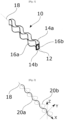
- FIG. 1 schematically illustrates in perspective a single passage channel 10 of a passage path of a heat exchanger according to an embodiment of the invention.
- the channel 10 is formed of an empty space 12 delimited by two plates 14a and 14b and two adjacent fins 16a and 16b of the heat exchanger.
- the channel extends in a main direction called the circulation axis 18, representing the direction in which a fluid passing through the exchanger moves in the channel.
- a section perpendicular to the direction axis forms a flat passage section closed by the walls formed by the two plates 14a and 14b and the two adjacent fins 16a and 16b.
- the plate 14a forms a plate called the upper plate and the plate 14b forms a plate called the lower plate.
- the fins are in contact with these two plates.
- FIG 2 schematically illustrates two oscillating curves 20a and 20b followed respectively by the plates 14a and 14b, and by the fins 16a and 16b, making it possible to obtain the undulating shape of the passage channel.
- the curves are here continuous and sinusoidal, but the curves can take different shapes, for example triangular, etc.
- the curves are oscillating.
- the two curves oscillate and are periodic (i.e. of constant frequency and constant maximum and minimum amplitude between each period).
- the first oscillating curve 20a represents the oscillation applied to the plates 14a and 14b and the second curve 20b represents the oscillation applied to the fins 16a and 16b.
- the combination at any point of the two curves 20a and 20b corresponds to a generator curve representing the circulation of the fluid in the passage channel 10.
- the curves here oscillate around the circulation axis, but can oscillate in different directions, as shown in the figure 3 .
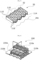
- FIG. 3 represents a passage path 30 of a heat exchanger according to an embodiment of the invention.
- a passage path 30 comprises several passage channels 110 and allows the circulation of a fluid, the fluid passing through the different passage channels 110 of the passage path 30.
- the passage path is formed by two plates (only one plate 114 being visible in the figure) and a plurality of fins 116, so as to compose the different channels 110 all oriented along axes 118 of parallel directions.
- one of the curves 20c followed by the plates forming the passage channels 110 is included in a plane orthogonal to the mean plane 32 of the plate 114 and thus forms the oscillating curve followed by the plate.
- the curve 20c oscillates around the mean plane 32 and therefore influences all the channels.
- each fin of the passage channels 110 is included in a plane comprising the direction axis of each passage channel 110.
- FIG. 4 represents a heat exchanger 200 according to an embodiment of the invention.
- the heat exchanger comprises four paths of passage, two passage paths 210a and 210b being intended for a first fluid and two passage paths 220a and 220b intended for a second fluid.
- the passage paths are arranged alternately so as to allow heat exchange between the first and second fluids.
- the passage paths are arranged so that the circulation axes are substantially perpendicular, so as to form a cross-pass exchanger.
Landscapes
- Engineering & Computer Science (AREA)
- Physics & Mathematics (AREA)
- Thermal Sciences (AREA)
- Mechanical Engineering (AREA)
- General Engineering & Computer Science (AREA)
- Heat-Exchange Devices With Radiators And Conduit Assemblies (AREA)
Claims (9)
- Wärmetauscher, der ausgestaltet ist, einen Wärmeaustausch zwischen einem ersten Fluid und einem zweiten Fluid zu ermöglichen, die in mindestens einem ersten Durchgangsweg bzw. einem zweiten Durchgangsweg zirkulieren, worin die Durchgangswege (30, 210a, 210b, 220a, 220b) durch Platten (14a, 14b, 114) und Rippen (16a, 16b, 116) des Wärmetauschers ausgebildet werden und ausgestaltet sind, jedes Fluid von einem Fluideinlass zu einem Fluidauslass zu leiten, worin die Fluide in mehreren Durchgangskanälen (10, 110) fließen, die jeweils aus einem geschlossenen Raum (12) bestehen, der durch zwei benachbarte Platten und zwei benachbarte Rippen begrenzt ist,worin sich jede Platte entlang einer nicht ebenen Fläche erstreckt, die zwischen dem Fluideinlass und dem Fluidauslass des zugehörigen Durchgangswegs definiert ist, worin die nicht ebene Fläche mindestens einer ersten Schwingungskurve (20a) entlang mindestens einer ersten Hauptrichtung um eine gemittelten Oberfläche der Platte folgt, jede Rippe eine obere Kante umfasst, die ausgestaltet ist, mit einer der benachbarten Platten, obere Platte genannt, in Kontakt zu sein, und eine untere Kante, die ausgestaltet ist, mit der anderen benachbarten Platte, untere Platte genannt, in Kontakt zu sein, worin jede Rippe zudem mindestens einer zweiten Schwingungskurve (20b) in mindestens einer zweiten Hauptrichtung um eine gemittelte Oberfläche der Rippe folgt, so dass jeder Durchgangsweg es dem Fluid ermöglicht, in dem geschlossenen Raum entlang einer Fluidrichtung zwischen dem Fluideinlass und dem Fluidauslass, der sogenannten Strömungsachse (18, 118), zu fließen, die an jedem Punkt der Kurve durch eine Generatrix definiert ist, die an jedem Punkt eine Kombination zumindest der ersten Schwingungskurve und der zweiten Schwingungskurve ist,dadurch gekennzeichnet, dass die Strömungsachsen der Kanäle des ersten Durchgangs im Wesentlichen orthogonal zu den Strömungsachsen der Kanäle des zweiten Durchgangs sind.
- Wärmetauscher nach Anspruch 1, dadurch gekennzeichnet, dass die erste Kurve (20a) und die zweite Kurve (20b) die folgenden Eigenschaften aufweisen:


- Wärmetauscher nach einem der Ansprüche 1 oder 2, dadurch gekennzeichnet, dass die erste Kurve (20a) und/oder die zweite Kurve (20b) kontinuierlich ist.
- Wärmetauscher nach einem der Ansprüche 1 oder 2, dadurch gekennzeichnet, dass die erste Kurve (20a) und/oder die zweite Kurve (20b) diskontinuierlich ist.
- Wärmetauscher nach einem der Ansprüche 1 bis 4, dadurch gekennzeichnet, dass die erste Kurve (20a) und/oder die zweite Kurve (20b) mit variabler Amplitude und/oder Frequenz schwingt.
- Wärmetauscher nach einem der Ansprüche 1 bis 5, dadurch gekennzeichnet, dass die Fluide gasförmig oder flüssig sind.
- Wärmetauscher nach einem der Ansprüche 1 bis 6, dadurch gekennzeichnet, dass dieser durch additive Fertigung hergestellt ist.
- Klimaanlagensystem, dadurch gekennzeichnet, dass dieses einen Wärmetauscher (200) nach einem der Ansprüche 1 bis 7 umfasst.
- Luftfahrzeug, dadurch gekennzeichnet, dass dieses einen Wärmetauscher (200) nach einem der Ansprüche 1 bis 7 umfasst.
Applications Claiming Priority (2)
| Application Number | Priority Date | Filing Date | Title |
|---|---|---|---|
| FR1915230A FR3105387B1 (fr) | 2019-12-20 | 2019-12-20 | Échangeur de chaleur à passages de fluide optimisés |
| PCT/FR2020/052436 WO2021123597A1 (fr) | 2019-12-20 | 2020-12-15 | Échangeur de chaleur à passages de fluide optimisés |
Publications (2)
| Publication Number | Publication Date |
|---|---|
| EP4078058A1 EP4078058A1 (de) | 2022-10-26 |
| EP4078058B1 true EP4078058B1 (de) | 2025-02-05 |
Family
ID=69811322
Family Applications (1)
| Application Number | Title | Priority Date | Filing Date |
|---|---|---|---|
| EP20845201.1A Active EP4078058B1 (de) | 2019-12-20 | 2020-12-15 | Wärmetauscher mit optimierten fluidkanälen |
Country Status (6)
| Country | Link |
|---|---|
| US (1) | US12203710B2 (de) |
| EP (1) | EP4078058B1 (de) |
| CN (1) | CN114829863A (de) |
| ES (1) | ES3010318T3 (de) |
| FR (1) | FR3105387B1 (de) |
| WO (1) | WO2021123597A1 (de) |
Citations (1)
| Publication number | Priority date | Publication date | Assignee | Title |
|---|---|---|---|---|
| EP3193125A1 (de) * | 2016-01-14 | 2017-07-19 | Hamilton Sundstrand Corporation | Wärmetauscherkanäle |
Family Cites Families (32)
| Publication number | Priority date | Publication date | Assignee | Title |
|---|---|---|---|---|
| US2567030A (en) * | 1947-07-11 | 1951-09-04 | Air Maze Corp | Filter panel |
| US2764257A (en) * | 1953-08-19 | 1956-09-25 | Air Maze Corp | Edge filter panel with uneven face |
| JPS548202B2 (de) * | 1972-12-07 | 1979-04-13 | ||
| SE423750B (sv) * | 1977-01-14 | 1982-05-24 | Munters Ab Carl | Anordning vid vermevexlare for sensibel och/eller latent vermeoverforing |
| US4333749A (en) * | 1980-10-24 | 1982-06-08 | The Marley Company | Drift eliminator structure for counterflow water cooling tower |
| US4460388A (en) * | 1981-07-17 | 1984-07-17 | Nippon Soken, Inc. | Total heat exchanger |
| US4410427A (en) * | 1981-11-02 | 1983-10-18 | Donaldson Company, Inc. | Fluid filtering device |
| DE8522627U1 (de) * | 1985-08-06 | 1985-09-19 | Röhm GmbH, 6100 Darmstadt | Plattenwärmetauscher |
| US5010594A (en) * | 1989-06-27 | 1991-04-30 | Japan Air Lines Co., Ltd. | Dampening mask for use in aircraft |
| JP3139681B2 (ja) * | 1999-05-31 | 2001-03-05 | 春男 上原 | 凝縮器 |
| US6273938B1 (en) * | 1999-08-13 | 2001-08-14 | 3M Innovative Properties Company | Channel flow filter |
| US6372076B1 (en) * | 1999-09-28 | 2002-04-16 | L&P Property Management Company | Convoluted multi-layer pad and process |
| WO2004070284A1 (en) * | 2003-02-03 | 2004-08-19 | Lg Electronics Inc. | Heat exchanger of ventilating system |
| JP3697523B2 (ja) * | 2003-10-10 | 2005-09-21 | 国立大学法人 東京大学 | 再生熱交換器、及び再生熱交換方法 |
| US7159649B2 (en) * | 2004-03-11 | 2007-01-09 | Thermal Corp. | Air-to-air heat exchanger |
| DE202005009948U1 (de) * | 2005-06-23 | 2006-11-16 | Autokühler GmbH & Co. KG | Wärmeaustauschelement und damit hergestellter Wärmeaustauscher |
| US7771517B2 (en) * | 2007-05-14 | 2010-08-10 | Global Finishing Solutions, L.L.C. | Filtering method |
| US8021466B2 (en) * | 2008-03-18 | 2011-09-20 | Carpenter Co. | Fluid flow filter and method of making and using |
| US20120037349A1 (en) * | 2009-04-28 | 2012-02-16 | Mitsubishi Electric Corporation | Heat exchange element |
| EP2426453B1 (de) * | 2009-04-28 | 2013-10-02 | Mitsubishi Electric Corporation | Gesamtwärmeaustauschelement |
| US9630132B2 (en) * | 2014-07-01 | 2017-04-25 | Caterpillar Inc. | Fluid filtering system |
| FR3028018B1 (fr) * | 2014-11-04 | 2019-03-22 | Valeo Systemes Thermiques | Element d'echange de chaleur adapte pour un echange de chaleur entre un premier et un deuxieme fluide, un faisceau d'echange comprenant l'element d'echange de chaleur et un echangeur de chaleur comprenant le faisceau d'echange |
| JP6548324B2 (ja) * | 2015-06-30 | 2019-07-24 | 東京ラヂエーター製造株式会社 | 熱交換器のインナーフィン |
| GB2565143B (en) * | 2017-08-04 | 2021-08-04 | Hieta Tech Limited | Heat exchanger |
| JP6642603B2 (ja) * | 2018-02-28 | 2020-02-05 | 株式会社富士通ゼネラル | 隔壁式熱交換器 |
| CN208155134U (zh) * | 2018-05-15 | 2018-11-27 | 郑州大学 | 一种新型板翅式换热器翅片 |
| EP3650799B1 (de) * | 2018-11-07 | 2021-12-15 | Borgwarner Emissions Systems Spain, S.L.U. | Rippenkörper für ein wärmetauscherrohr |
| US20200166293A1 (en) * | 2018-11-27 | 2020-05-28 | Hamilton Sundstrand Corporation | Weaved cross-flow heat exchanger and method of forming a heat exchanger |
| CN109883238A (zh) * | 2019-03-08 | 2019-06-14 | 西安交通大学 | 一种板翅式热交换器芯体及其翅片结构 |
| KR102223356B1 (ko) * | 2020-07-13 | 2021-03-05 | 송길섭 | 대향류 전열교환기의 제조방법 |
| US20230235916A1 (en) * | 2020-08-11 | 2023-07-27 | Mitsubishi Electric Corporation | Total heat exchange element and ventilator |
| US12025383B2 (en) * | 2021-03-30 | 2024-07-02 | Mitsubishi Electric Us, Inc. | Air-to-air heat recovery core and method of operating the same |
-
2019
- 2019-12-20 FR FR1915230A patent/FR3105387B1/fr active Active
-
2020
- 2020-12-15 CN CN202080087136.4A patent/CN114829863A/zh active Pending
- 2020-12-15 US US17/783,068 patent/US12203710B2/en active Active
- 2020-12-15 EP EP20845201.1A patent/EP4078058B1/de active Active
- 2020-12-15 WO PCT/FR2020/052436 patent/WO2021123597A1/fr not_active Ceased
- 2020-12-15 ES ES20845201T patent/ES3010318T3/es active Active
Patent Citations (1)
| Publication number | Priority date | Publication date | Assignee | Title |
|---|---|---|---|---|
| EP3193125A1 (de) * | 2016-01-14 | 2017-07-19 | Hamilton Sundstrand Corporation | Wärmetauscherkanäle |
Also Published As
| Publication number | Publication date |
|---|---|
| FR3105387B1 (fr) | 2021-11-26 |
| WO2021123597A1 (fr) | 2021-06-24 |
| EP4078058A1 (de) | 2022-10-26 |
| CN114829863A (zh) | 2022-07-29 |
| ES3010318T3 (en) | 2025-04-02 |
| FR3105387A1 (fr) | 2021-06-25 |
| US20230023640A1 (en) | 2023-01-26 |
| US12203710B2 (en) | 2025-01-21 |
Similar Documents
| Publication | Publication Date | Title |
|---|---|---|
| EP0430752B1 (de) | Wärmetauscher mit einer umfangsförmigen Zirkulation | |
| EP2294348B1 (de) | Kondensator | |
| EP1061319B1 (de) | Flüssigkeitsführendes Rohr und seine Verwendung in einem Kraftfahrzeugkühler | |
| EP3662222B1 (de) | Wärmetauscher avec distriteur | |
| FR2824895A1 (fr) | Ailette ondulee a persiennes pour echangeur de chaleur a plaques, et echangeur a plaques muni de telles ailettes | |
| FR2995397A1 (fr) | Intercalaire d'echangeur de chaleur. | |
| EP2734801A1 (de) | Wärmetauscher und entsprechendes flachrohr sowie platte | |
| EP4078058B1 (de) | Wärmetauscher mit optimierten fluidkanälen | |
| EP3645184B1 (de) | Rohr für einen wärmetauscher mit störvorrichtung | |
| FR3092906A1 (fr) | Echangeur de chaleur | |
| FR3061283B1 (fr) | Dispositif de repartition d’un fluide refrigerant pour une boite collectrice d’un echangeur de chaleur | |
| EP2936031B1 (de) | Wärmetauscherelement und entsprechender wärmetauscher | |
| EP0445006B1 (de) | Wärmetauscher mit kreisförmiger Strömung | |
| EP4423447A1 (de) | Wärmetauscherplattenpaar mit nuten und ausnehmungen | |
| EP3794299A1 (de) | Wärmetauscher für ein kraftfahrzeug | |
| FR3073611B1 (fr) | Tube pour echangeur de chaleur avec dispositif de perturbation de geometrie variable | |
| FR3137752A1 (fr) | Dispositif de régulation thermique, notamment de refroidissement | |
| WO2024008649A1 (fr) | Dispositif de regulation thermique, notamment de refroidissement | |
| FR3066812A1 (fr) | Ailette pour echangeur de chaleur comprenant deux echancrures | |
| WO2026041705A1 (fr) | Echangeur de chaleur | |
| EP4630747A1 (de) | Wärmetauscher mit zellstruktur | |
| EP4551888A1 (de) | Vorrichtung zur thermischen regelung, insbesondere zur kühlung | |
| WO2025149278A1 (fr) | Système de conditionnement thermique | |
| EP3207326B1 (de) | Wärmetauscher | |
| FR3153883A1 (fr) | Echangeur de chaleur a distribution améliorée |
Legal Events
| Date | Code | Title | Description |
|---|---|---|---|
| STAA | Information on the status of an ep patent application or granted ep patent |
Free format text: STATUS: UNKNOWN |
|
| STAA | Information on the status of an ep patent application or granted ep patent |
Free format text: STATUS: THE INTERNATIONAL PUBLICATION HAS BEEN MADE |
|
| PUAI | Public reference made under article 153(3) epc to a published international application that has entered the european phase |
Free format text: ORIGINAL CODE: 0009012 |
|
| STAA | Information on the status of an ep patent application or granted ep patent |
Free format text: STATUS: REQUEST FOR EXAMINATION WAS MADE |
|
| 17P | Request for examination filed |
Effective date: 20220517 |
|
| AK | Designated contracting states |
Kind code of ref document: A1 Designated state(s): AL AT BE BG CH CY CZ DE DK EE ES FI FR GB GR HR HU IE IS IT LI LT LU LV MC MK MT NL NO PL PT RO RS SE SI SK SM TR |
|
| DAV | Request for validation of the european patent (deleted) | ||
| DAX | Request for extension of the european patent (deleted) | ||
| STAA | Information on the status of an ep patent application or granted ep patent |
Free format text: STATUS: EXAMINATION IS IN PROGRESS |
|
| 17Q | First examination report despatched |
Effective date: 20231108 |
|
| GRAP | Despatch of communication of intention to grant a patent |
Free format text: ORIGINAL CODE: EPIDOSNIGR1 |
|
| STAA | Information on the status of an ep patent application or granted ep patent |
Free format text: STATUS: GRANT OF PATENT IS INTENDED |
|
| GRAJ | Information related to disapproval of communication of intention to grant by the applicant or resumption of examination proceedings by the epo deleted |
Free format text: ORIGINAL CODE: EPIDOSDIGR1 |
|
| STAA | Information on the status of an ep patent application or granted ep patent |
Free format text: STATUS: EXAMINATION IS IN PROGRESS |
|
| GRAP | Despatch of communication of intention to grant a patent |
Free format text: ORIGINAL CODE: EPIDOSNIGR1 |
|
| STAA | Information on the status of an ep patent application or granted ep patent |
Free format text: STATUS: GRANT OF PATENT IS INTENDED |
|
| INTG | Intention to grant announced |
Effective date: 20240828 |
|
| INTC | Intention to grant announced (deleted) | ||
| INTG | Intention to grant announced |
Effective date: 20240927 |
|
| GRAS | Grant fee paid |
Free format text: ORIGINAL CODE: EPIDOSNIGR3 |
|
| GRAA | (expected) grant |
Free format text: ORIGINAL CODE: 0009210 |
|
| STAA | Information on the status of an ep patent application or granted ep patent |
Free format text: STATUS: THE PATENT HAS BEEN GRANTED |
|
| AK | Designated contracting states |
Kind code of ref document: B1 Designated state(s): AL AT BE BG CH CY CZ DE DK EE ES FI FR GB GR HR HU IE IS IT LI LT LU LV MC MK MT NL NO PL PT RO RS SE SI SK SM TR |
|
| REG | Reference to a national code |
Ref country code: GB Ref legal event code: FG4D Free format text: NOT ENGLISH |
|
| REG | Reference to a national code |
Ref country code: CH Ref legal event code: EP |
|
| REG | Reference to a national code |
Ref country code: DE Ref legal event code: R096 Ref document number: 602020045755 Country of ref document: DE |
|
| REG | Reference to a national code |
Ref country code: IE Ref legal event code: FG4D Free format text: LANGUAGE OF EP DOCUMENT: FRENCH |
|
| REG | Reference to a national code |
Ref country code: ES Ref legal event code: FG2A Ref document number: 3010318 Country of ref document: ES Kind code of ref document: T3 Effective date: 20250402 |
|
| REG | Reference to a national code |
Ref country code: NL Ref legal event code: MP Effective date: 20250205 |
|
| PG25 | Lapsed in a contracting state [announced via postgrant information from national office to epo] |
Ref country code: RS Free format text: LAPSE BECAUSE OF FAILURE TO SUBMIT A TRANSLATION OF THE DESCRIPTION OR TO PAY THE FEE WITHIN THE PRESCRIBED TIME-LIMIT Effective date: 20250505 |
|
| PG25 | Lapsed in a contracting state [announced via postgrant information from national office to epo] |
Ref country code: FI Free format text: LAPSE BECAUSE OF FAILURE TO SUBMIT A TRANSLATION OF THE DESCRIPTION OR TO PAY THE FEE WITHIN THE PRESCRIBED TIME-LIMIT Effective date: 20250205 |
|
| PG25 | Lapsed in a contracting state [announced via postgrant information from national office to epo] |
Ref country code: PL Free format text: LAPSE BECAUSE OF FAILURE TO SUBMIT A TRANSLATION OF THE DESCRIPTION OR TO PAY THE FEE WITHIN THE PRESCRIBED TIME-LIMIT Effective date: 20250205 |
|
| REG | Reference to a national code |
Ref country code: LT Ref legal event code: MG9D |
|
| PG25 | Lapsed in a contracting state [announced via postgrant information from national office to epo] |
Ref country code: NO Free format text: LAPSE BECAUSE OF FAILURE TO SUBMIT A TRANSLATION OF THE DESCRIPTION OR TO PAY THE FEE WITHIN THE PRESCRIBED TIME-LIMIT Effective date: 20250505 Ref country code: IS Free format text: LAPSE BECAUSE OF FAILURE TO SUBMIT A TRANSLATION OF THE DESCRIPTION OR TO PAY THE FEE WITHIN THE PRESCRIBED TIME-LIMIT Effective date: 20250605 |
|
| PG25 | Lapsed in a contracting state [announced via postgrant information from national office to epo] |
Ref country code: NL Free format text: LAPSE BECAUSE OF FAILURE TO SUBMIT A TRANSLATION OF THE DESCRIPTION OR TO PAY THE FEE WITHIN THE PRESCRIBED TIME-LIMIT Effective date: 20250205 |
|
| PG25 | Lapsed in a contracting state [announced via postgrant information from national office to epo] |
Ref country code: HR Free format text: LAPSE BECAUSE OF FAILURE TO SUBMIT A TRANSLATION OF THE DESCRIPTION OR TO PAY THE FEE WITHIN THE PRESCRIBED TIME-LIMIT Effective date: 20250205 |
|
| PG25 | Lapsed in a contracting state [announced via postgrant information from national office to epo] |
Ref country code: LV Free format text: LAPSE BECAUSE OF FAILURE TO SUBMIT A TRANSLATION OF THE DESCRIPTION OR TO PAY THE FEE WITHIN THE PRESCRIBED TIME-LIMIT Effective date: 20250205 Ref country code: PT Free format text: LAPSE BECAUSE OF FAILURE TO SUBMIT A TRANSLATION OF THE DESCRIPTION OR TO PAY THE FEE WITHIN THE PRESCRIBED TIME-LIMIT Effective date: 20250605 |
|
| PG25 | Lapsed in a contracting state [announced via postgrant information from national office to epo] |
Ref country code: GR Free format text: LAPSE BECAUSE OF FAILURE TO SUBMIT A TRANSLATION OF THE DESCRIPTION OR TO PAY THE FEE WITHIN THE PRESCRIBED TIME-LIMIT Effective date: 20250506 Ref country code: BG Free format text: LAPSE BECAUSE OF FAILURE TO SUBMIT A TRANSLATION OF THE DESCRIPTION OR TO PAY THE FEE WITHIN THE PRESCRIBED TIME-LIMIT Effective date: 20250205 |
|
| REG | Reference to a national code |
Ref country code: AT Ref legal event code: MK05 Ref document number: 1764951 Country of ref document: AT Kind code of ref document: T Effective date: 20250205 |
|
| PG25 | Lapsed in a contracting state [announced via postgrant information from national office to epo] |
Ref country code: SE Free format text: LAPSE BECAUSE OF FAILURE TO SUBMIT A TRANSLATION OF THE DESCRIPTION OR TO PAY THE FEE WITHIN THE PRESCRIBED TIME-LIMIT Effective date: 20250205 |
|
| PG25 | Lapsed in a contracting state [announced via postgrant information from national office to epo] |
Ref country code: SM Free format text: LAPSE BECAUSE OF FAILURE TO SUBMIT A TRANSLATION OF THE DESCRIPTION OR TO PAY THE FEE WITHIN THE PRESCRIBED TIME-LIMIT Effective date: 20250205 |
|
| PG25 | Lapsed in a contracting state [announced via postgrant information from national office to epo] |
Ref country code: DK Free format text: LAPSE BECAUSE OF FAILURE TO SUBMIT A TRANSLATION OF THE DESCRIPTION OR TO PAY THE FEE WITHIN THE PRESCRIBED TIME-LIMIT Effective date: 20250205 |
|
| PG25 | Lapsed in a contracting state [announced via postgrant information from national office to epo] |
Ref country code: AT Free format text: LAPSE BECAUSE OF FAILURE TO SUBMIT A TRANSLATION OF THE DESCRIPTION OR TO PAY THE FEE WITHIN THE PRESCRIBED TIME-LIMIT Effective date: 20250205 |
|
| PG25 | Lapsed in a contracting state [announced via postgrant information from national office to epo] |
Ref country code: CZ Free format text: LAPSE BECAUSE OF FAILURE TO SUBMIT A TRANSLATION OF THE DESCRIPTION OR TO PAY THE FEE WITHIN THE PRESCRIBED TIME-LIMIT Effective date: 20250205 Ref country code: EE Free format text: LAPSE BECAUSE OF FAILURE TO SUBMIT A TRANSLATION OF THE DESCRIPTION OR TO PAY THE FEE WITHIN THE PRESCRIBED TIME-LIMIT Effective date: 20250205 |
|
| PG25 | Lapsed in a contracting state [announced via postgrant information from national office to epo] |
Ref country code: RO Free format text: LAPSE BECAUSE OF FAILURE TO SUBMIT A TRANSLATION OF THE DESCRIPTION OR TO PAY THE FEE WITHIN THE PRESCRIBED TIME-LIMIT Effective date: 20250205 |
|
| PG25 | Lapsed in a contracting state [announced via postgrant information from national office to epo] |
Ref country code: SK Free format text: LAPSE BECAUSE OF FAILURE TO SUBMIT A TRANSLATION OF THE DESCRIPTION OR TO PAY THE FEE WITHIN THE PRESCRIBED TIME-LIMIT Effective date: 20250205 |
|
| REG | Reference to a national code |
Ref country code: DE Ref legal event code: R097 Ref document number: 602020045755 Country of ref document: DE |
|
| PLBE | No opposition filed within time limit |
Free format text: ORIGINAL CODE: 0009261 |
|
| STAA | Information on the status of an ep patent application or granted ep patent |
Free format text: STATUS: NO OPPOSITION FILED WITHIN TIME LIMIT |
|
| PGFP | Annual fee paid to national office [announced via postgrant information from national office to epo] |
Ref country code: GB Payment date: 20251229 Year of fee payment: 6 |
|
| 26N | No opposition filed |
Effective date: 20251106 |
|
| PGFP | Annual fee paid to national office [announced via postgrant information from national office to epo] |
Ref country code: FR Payment date: 20251223 Year of fee payment: 6 |
|
| PGFP | Annual fee paid to national office [announced via postgrant information from national office to epo] |
Ref country code: ES Payment date: 20260102 Year of fee payment: 6 |
|
| PGFP | Annual fee paid to national office [announced via postgrant information from national office to epo] |
Ref country code: DE Payment date: 20251230 Year of fee payment: 6 |
|
| PGFP | Annual fee paid to national office [announced via postgrant information from national office to epo] |
Ref country code: IT Payment date: 20251229 Year of fee payment: 6 |