EP4077935B1 - Selbstklemmender kabelschutz zum klemmen von stromkabeln eines stromkabelbündels einer kabelhalteranordnung in einer windturbine, kabelhalter und windturbine - Google Patents
Selbstklemmender kabelschutz zum klemmen von stromkabeln eines stromkabelbündels einer kabelhalteranordnung in einer windturbine, kabelhalter und windturbine Download PDFInfo
- Publication number
- EP4077935B1 EP4077935B1 EP21707621.5A EP21707621A EP4077935B1 EP 4077935 B1 EP4077935 B1 EP 4077935B1 EP 21707621 A EP21707621 A EP 21707621A EP 4077935 B1 EP4077935 B1 EP 4077935B1
- Authority
- EP
- European Patent Office
- Prior art keywords
- cable
- self
- clamping
- power
- guard
- Prior art date
- Legal status (The legal status is an assumption and is not a legal conclusion. Google has not performed a legal analysis and makes no representation as to the accuracy of the status listed.)
- Active
Links
Images


Classifications
-
- F—MECHANICAL ENGINEERING; LIGHTING; HEATING; WEAPONS; BLASTING
- F03—MACHINES OR ENGINES FOR LIQUIDS; WIND, SPRING, OR WEIGHT MOTORS; PRODUCING MECHANICAL POWER OR A REACTIVE PROPULSIVE THRUST, NOT OTHERWISE PROVIDED FOR
- F03D—WIND MOTORS
- F03D80/00—Details, components or accessories not provided for in groups F03D1/00 - F03D17/00
- F03D80/80—Arrangement of components within nacelles or towers
- F03D80/82—Arrangement of components within nacelles or towers of electrical components
- F03D80/85—Cabling
-
- F—MECHANICAL ENGINEERING; LIGHTING; HEATING; WEAPONS; BLASTING
- F16—ENGINEERING ELEMENTS AND UNITS; GENERAL MEASURES FOR PRODUCING AND MAINTAINING EFFECTIVE FUNCTIONING OF MACHINES OR INSTALLATIONS; THERMAL INSULATION IN GENERAL
- F16L—PIPES; JOINTS OR FITTINGS FOR PIPES; SUPPORTS FOR PIPES, CABLES OR PROTECTIVE TUBING; MEANS FOR THERMAL INSULATION IN GENERAL
- F16L3/00—Supports for pipes, cables or protective tubing, e.g. hangers, holders, clamps, cleats, clips, brackets
- F16L3/22—Supports for pipes, cables or protective tubing, e.g. hangers, holders, clamps, cleats, clips, brackets specially adapted for supporting a number of parallel pipes at intervals
- F16L3/223—Supports for pipes, cables or protective tubing, e.g. hangers, holders, clamps, cleats, clips, brackets specially adapted for supporting a number of parallel pipes at intervals each support having one transverse base for supporting the pipes
-
- Y—GENERAL TAGGING OF NEW TECHNOLOGICAL DEVELOPMENTS; GENERAL TAGGING OF CROSS-SECTIONAL TECHNOLOGIES SPANNING OVER SEVERAL SECTIONS OF THE IPC; TECHNICAL SUBJECTS COVERED BY FORMER USPC CROSS-REFERENCE ART COLLECTIONS [XRACs] AND DIGESTS
- Y02—TECHNOLOGIES OR APPLICATIONS FOR MITIGATION OR ADAPTATION AGAINST CLIMATE CHANGE
- Y02E—REDUCTION OF GREENHOUSE GAS [GHG] EMISSIONS, RELATED TO ENERGY GENERATION, TRANSMISSION OR DISTRIBUTION
- Y02E10/00—Energy generation through renewable energy sources
- Y02E10/70—Wind energy
- Y02E10/72—Wind turbines with rotation axis in wind direction
Definitions
- the present invention is directed to a self-clamping cable guard for clamping power cables of a power cable bundle of a cable support arrangement in a wind turbine, cable support arrangement and a wind turbine.
- the nacelle of a wind turbine is usually mounted to the tower by means of a yaw interface, so that the nacelle can be yawed. This allows the rotor blades of the wind turbine to be optimally positioned into the wind.
- Electricity produced by the generator of the wind turbine is transported from the generator's windings to a transmission cable arrangement in the tower of the wind turbine, and usually transported using multiple power-phase cable sets, depending on the power rating of the wind turbine. For example, power from a 4 MW generator can be transported over seven sets of three-phase cables, so that twenty-one power cables are required.
- the power cables extend from the generator into the tower and down through the tower to an overland or subsea power transmission line.
- the power cables themselves are heavy, and must be supported in the tower. Therefore, over most of the tower height, the cables are fixed by suitable holders in an essentially vertical stationary transmission cable arrangement.
- an upper portion of the power cables - i.e. some length of a power cable arrangement between the generator and the stationary fixed transmission cable arrangement in the tower - must allow for a yaw motion of the nacelle. It is usual for a yaw drive to be able to turn the nacelle through two full revolutions in either direction. Therefore, this length of the power cable arrangement must be flexible enough to permit such a rotational motion of the nacelle.
- known cable arrangements in a flexible portion between the yaw drive level and the transmission cable arrangement - referred to as a "power cable twist arrangement" or “power cable loop” - try to hold the cables in such a way as to keep the individual cables apart, and to ensure that the rotational displacement of the nacelle is transferred evenly over the length of the flexible portion.
- the individual cables of the power cable twist arrangement are passed through holes in a number of cable guides. Several cable guides can be used and spaced at intervals. Such an arrangement ensures that the individual cables of the power cable twist arrangement are held at a distance apart over the length of the power cables in this flexible portion.
- the power cable loop is very large and cumbersome.
- the power cable loop is assembled by arranging a suitable number of cable guides over a set of interface power cables that will connect the generator to the transmission cables secured to the tower wall.
- eight cable guides each with twelve through-openings, can be arranged at intervals over a set of twelve interface power cables.
- the position of a cable guide along the power cable loop is fixed by securing it to one or more of the power cables, for example using a cable tie.
- such ties should not be too tight, since some degree of freedom is needed to allow the power cables to twist relative to each other and relative to the cable guide during a yawing motion.
- a cable guide can slip downwards along the power cable loop, so that eventually the cable guides are no longer positioned at regular intervals and cannot fulfil their intended functions of keeping the power cables apart and distributing the yawing motion along the length of the power cable loop.
- the length of the flexible portion or power cable loop can be about 10 to 12 m or more.
- a cable support arrangement is realized to support a plurality of power cable bundles in an upper region of a wind turbine tower, which cable support arrangement comprises a plurality of cable bundle guides, wherein a cable bundle guide comprises a plurality of through-openings, wherein each through-opening is realized to encompass a power cable bundle comprising a plurality of power cables and an offset fixation means realized to maintain an offset distance between consecutive cable bundle guides.
- US 2015/0222106 A1 discloses an apparatus for routing cables in wind turbines, in which a plurality of bushings for at least one cable are distributed on at least one base body that has preferably round contour.
- the bushings are provided with a guiding arrangement which permits the respective cable to move relative to the part of the bushing that surrounds the guiding arrangement.
- a power cable is usually a thick copper cable encased in insulating sheath, and only has a limited degree of flexibility.
- the power cables become hot.
- the flexible portion twists to follow a yawing motion of the nacelle, a power cable can be pressed with some force against the edge of the cable guide hole through which it passes, so that the cable is stressed.
- a hot power cable can become bent or otherwise distorted as a result.
- the insulation of the cable can wear, revealing the cable core (usually multiple strands of copper wire twisted into a cable). Repeated stress can result in damage to the core of the cable, for example the individual copper strands can fracture or break. Such damage can lead to a cable fire.
- the object is solved by means of a self-clamping cable guard for clamping power cables of a power cable bundle of a cable support arrangement in a wind turbine, whereby the self-clamping cable guard comprises three recesses arranged about a central longitudinal axis of the self-clamping cable guard for positively clamping a power cable of the power cable bundle inside of each of the three recesses, and whereby the self-clamping cable guard comprises three wear protection plates arranged about the central longitudinal axis, whereby each of the three recesses comprises an open side for insertion of a respective power cable of the power cable bundle therein, each of the open sides of one of the three recesses being respectively limited by two of the three wear protection plates to protect the power cables clamped inside the recesses from wear.
- the self-clamping cable guard clamps the power cables of a power cable bundle so that they are arranged in a predefined position with respect to each other and protects them from wear by means of the wear protection plates.
- the cable guard being self-clamping means that there are no exterior clamping means for interlocking the power cables in the recesses of the self-clamping cable guard. Instead, the cable guard clamps the power cables by itself. This may be achieved by means of an elastic and/or flexible design of the self-clamping cable guard and/or by undersizing the recesses with respect to the power cables. Undersizing in particular means that the surface of the recesses are made slightly smaller than the cross section of the power cables such that the recesses are widened when the power cables are inserted therein. In a circular design of the recesses and circular power cables, the diameter of the recesses may be smaller than the diameter of the power cables to provide undersizing of the recesses with respect to the power cables. Thereby, a clamping force acts on the power cable when the power cable is inserted into the recess by virtue of the widened recess due to the inserted power cable and/or due to the elastic and/or flexible design of the self-clamping cable guard.
- the self-clamping cable guard may be used for any cables, in particular power cables, of the wind turbine.
- the preferred application of the self-clamping cable guard is to clamp the power cables of a power cable bundle of the cable support arrangement in a wind turbine.
- the self-clamping cable guard comprises three recesses. However, it is possible that the self-clamping cable guard comprises more than three recesses. But it is preferred, that the self-clamping cable guard comprises exactly three recesses. Thereby, in each of the recesses a power cable of a power cable bundle with three power cables may be clamped. Each of the three power cables may correspond to one phase for a three-phase generator of the wind turbine.
- the three recesses may be arranged in a triangular form.
- the central longitudinal axis runs through a center point of the self-clamping cable guard and along its length.
- the recesses may be round, in particular circular, inside of the self-clamping cable guard.
- the circular recesses may have a tube-like shape inside of the self-clamping cable guard and along its length. Thereby, round, in particular circular, power cables may be positively clamped inside of the circular recesses with ease.
- the wear protection plates may be partially arranged around the recesses.
- the wear protection plates must not be separate parts but merely provide plate-like protection of the power cables from wear.
- the wear protection plates may have a flat or substantially flat wear protection surface.
- the self-clamping cable guard is made from an elastic and/or flexible material such that the recesses may be elastically widened for receiving the power cables and elastically reset to clamp the power cables.
- a plastic in particular a hardened plastic, may be used as a material or the self-clamping cable guard, for example.
- the self-clamping cable guard comprises a center portion, whereby the center portion has a center point congruent with the central longitudinal axis and the center portion has the shape of a circular triangle with concave circular arc edges.
- the recesses may have the concave circular arc edges of the circular triangle shape as edges thereof. In such a design, the recesses and thereby the power cables are clamped in close proximity to each other such that the size of the self-clamping cable guard can be kept conveniently small.
- the self-clamping cable guard comprises three outer portions extending outwards from the center portion, whereby each of the outer portions is attached to a vertex part of the circular triangle shape of the center portion.
- the vertex part must not have a vertex but is the part having the lowest thickness of the center portion or, in other words, is where the concave circular arc edges of its circular triangle shape run together.
- the clamping force for the power cables may then be applied by means of the outer portions and the concave circular arc edges of the circular triangle shape of the center portion. Thereby, a particular even spread of the clamping force on the power cables may be achieved.
- each of the outer portions has the shape of a circular triangle with two concave circular arc edges and one straight edge, wherein the straight edge is a wear protection surface of the three wear protection plates.
- the two concave circular arc edges of the circular triangle shape of the outer portions apply the clamping force together with the concave circular arc edges of the circular triangle shape of the center portion.
- wear protection surfaces are provided as straight edges. Thereby, force applied onto the wear protection plates may provide further force intensifying the clamping and ensure safe clamping of the power cables inside of the self-clamping cable guard.
- the wear protection plates are congruent with an imaginary triangle, the imaginary triangle having a center point congruent with the central longitudinal axis and circumscribing the self-clamping cable guard.
- the wear protection plates are arranged in a triangle shape and able to protect the power cables from three sides from wear.
- the self-clamping cable guard is monolithically designed.
- the self-clamping cable guard may be made from one single piece and material. This enables particularly low-cost production of the self-clamping cable guard.
- the self-clamping cable guard is injection molded. Thereby, the self-clamping cable guard is produced at particularly low costs. A long self-clamping cable guard can be produced and afterwards cut to self-clamping cable guards of a required length.
- the object is solved by means of a cable support arrangement for a wind turbine comprising multiple self-clamping cable guards according to the first aspect of the invention, whereby the cable support arrangement comprises at least one cable bundle guide and multiple power cable bundles, each power cable bundle consisting of three power cables, and whereby each of the multiple self-clamping cable guards clamps in every one of its three recesses one of the three power cables of each of the multiple power cable bundles, and whereby each one of the multiple self-clamping cable guards with the power cables clamped inside thereof is arranged in one of multiple through-openings inside of the at least one cable bundle guide.
- the three power cables of each of the power cable bundle are protected from wear when moving inside the through-openings due to protection by means of the wear protection plates of the self-clamping cable guards clamping the three power cables.
- Multiple cable bundle guides may be us used to hold the power cable bundles at a certain distance from each other. Adjacent pairs of cable bundle guides may be secured to each other by wires of essentially equal length or other means.
- the shape of the multiple through-openings in the at least one cable bundle guide is based on a cross-sectional shape of the power cable bundle.
- the through-openings may be dimensioned to allow some clearance between their edges and the self-clamping cable guards or for form-fit of the self-clamping cable guards in the through-openings.
- the multiple through-openings inside of the at least one cable bundle guide have a triangular shape with straight edges and the wear protection plates of the self-clamping cable guards are arranged parallel to the straight edges of the triangular shape of the through-openings.
- the straight edges of the triangular shape of the through openings are aligned with the wear protection plates such that the wear protection plates are evenly subjected to wear and the power cables cannot be subjected to wear at the open sides of the recesses of the self-clamping cable guard.
- the at least one cable bundle guide comprises a tilting mechanism for tilting the cable bundle guide around a tilting axis perpendicular to the central longitudinal axis of the multiple self-clamping cable guards. This allows for further flexibility of the power cable bundle guide with respect to the movement of the power cable bundles and thus further reduces wear.
- the cable bundle guide is a circular plate and the multiple through-openings are arranged about a center point of the circular flat plate. Thereby, a compact configuration of the cable bundle guide is achieved.
- the cable support arrangement may be arranged to support the multiple power cable bundles in an upper region of a tower of a wind turbine. Further, the cable support arrangement may comprise an offset fixation means realized to maintain an offset distance between consecutive cable bundle guides.
- the offset fixation means ensures that the cable bundle guides remain at regular intervals, so that these always fulfil their intended functions of keeping the power cable bundles apart and distributing the yawing motion along the length of the power cable bundles.
- adjacent cable bundle guides may be connected by the offset fixation means, so that it is sufficient to secure the position of only one upper cable bundle guide at some point in order to fix the positions of the remaining cable bundle guides.
- the objective is solved by means of a wind turbine comprising a nacelle mounted on top of a tower of the wind turbine, a generator arranged inside the nacelle for generating electricity and at least one self-clamping cable guard according to the first aspect of the invention or a cable support arrangement according to the second aspect of the invention.
- a plurality of power cable bundles may extend from the generator to a stationary transmission cable arrangement in an upper region of the tower.
- the wind turbine may further be arranged to allow a yaw displacement of the nacelle.
- the cable support arrangement according to the second aspect of the invention may be arranged to support the multiple power cable bundles in the upper region of the tower.
- FIGURE 1 shows an embodiment of a wind turbine 5 according to the invention.
- the wind turbine 5 comprises a generator 3 housed in a nacelle 4 mounted on top of a tower 2.
- the generator 3 generates power as the rotor blades 50 of the wind turbine 5 rotate.
- the nacelle 4 can be yawed so that the rotor blades 50 are always optimally placed into the wind.
- the power is transported over a power cable loop 30L to a fixed transmission cable arrangement 31.
- the fixed transmission cable arrangement 31 may for example be secured to the wall of the tower 2.
- the function of the power cable loop 30L is to cope with the rotation of the nacelle 3 about a vertical axis.
- a nacelle may be yawed up to 720° in one direction before the direction of rotation is reversed.
- the power cable loop 30L generally comprises a plurality of power cables 30, depending on the number of generator poles and the number of power phases.
- a five-pole three-phase generator will have 15 power cables 30 in the power cable loop 30L leading from the generator 3 to the transmission cable arrangement 31.
- the power cable loop 30L is fixed only at the generator 3, and to a vertical displacement means 32 which can move upwards or downwards as the length of the power cable loop 30L changes in response to a yawing action.
- the fixation of the power cable loop 30L according to the invention will be explained in the following.
- FIGURE 2 shows an embodiment of a cable support arrangement 1 according to the state of the art, viewed from below inside the tower 2, looking upward towards an entry point 21 at the top level 20 of the tower 2.
- the nacelle is in a 'null' position and the power cables 30 of the power cable loop 30L hang straight down from the top level 20 of the tower 2.
- the power cables are arranged in bundles 30B of three power cables 30 for a three-phase generator.
- Multiple cable bundle guides 10 are used to hold the power cable bundles 30B at a certain distance from each other. Adjacent pairs of cable bundle guides 10 are secured to each other by wires 11 of essentially equal length. The wires 11 ensure that the cable bundle guides 10 cannot slip down along the power cable loop 30L. As long as an uppermost cable bundle guide 10 is secured near the upper level 20, for example close to a point of entry 21, the positions of the remaining cable bundle guides 10 are fixed.
- FIGURE 3 shows the cable support arrangement 1 of FIG. 2 in a second position.
- the nacelle has been yawed by some amount, so that the power cable loop 30L has twisted, and a torque arm 32 has moved upward by a corresponding amount.
- the cable bundle guides 10 ensure that the power cable bundles 30B retain their relative orientations.
- the shape of a through-opening 100 ensures that damage to the cables 30 of a power cable bundle 30B is avoided.
- FIGURE 4 illustrates a form of a cable bundle guide 10 according to the state of the art with seven through-openings 100, each of which is dimensioned to accommodate a three-cable bundle 30B with some ease.
- the edges of the through-openings 100 are rounded to avoid pressure points acting on the power cables when the power cable loop 30L is twisted. Because the power cables are arranged in bundles 30B, the diameter d 10 of the cable bundle guide 10 is small compared to separate arrangement of power cables in through-openings of a cable bundle guide 10.
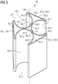
- FIGURE 5 shows an embodiment of a self-clamping cable guard 40 according to the invention, which is used in the wind turbine 5 of FIG. 1 , such that it is included in the cable support arrangement 1 of FIGS. 2 and 3 and the cable bundle guide 10 of FIG. 4 .
- the self-clamping cable guard 40 comprises a center portion 41 and three outer portions 43.1, 43.2, 43.3.
- the self-clamping cable guard 40 is designed monolithically from an elastic material, such as a hardened plastic, and injection molded.
- the center portion 41 has a center point congruent with the central longitudinal axis L 40 of the self-clamping cable guard 40. Further, the center portion 41 has the shape of a circular triangle with concave circular arc edges 42.1, 42.2, 42.3. The concave circular arc edges 42.1, 42.2, 42.3 run between vertex parts 48.1, 48.2, 48.3 of the circular triangle shape of the center portion 41.
- Three outer portions 43.1, 43.2, 43.3 of the self-clamping cable guard 40 are arranged at the vertex parts 48.1, 48.2, 48.3.
- Each of the three outer portions 43.1, 43.2, 43.3 has the shape of a circular triangle with two concave circular arc edges 44.1, 44.2, 44.3, 44.4, 44.5, 44.6 and one straight edge 49.1, 49.2, 49.3.
- the straight edges 49.1, 49.2, 49.3 of the outer portions 43.1, 43.2, 43.3 are wear protection surfaces 49.1, 49.2, 49.3 of wear protection plates 45.1, 45.2, 45.3 formed by the outer portions 43.1, 43.2, 43.3.
- the respective concave circular arc edges 42.1, 42.2, 42.3 of the center portion 41 and the respective concave circular arc edges 44.1, 44.2, 44.3, 44.4, 44.5, 44.6 of the outer portions 43.1, 43.2, 43.3 form circular recesses 46.1, 46.2, 46.3 for insertion of the power cables 30 therein.
- the recesses 46.1, 46.2, 46.3 are elastically widened and the power cables 30 are inserted therein through open sides 47.1, 47.2, 47.3 of the recesses 46.1, 46.2, 46.3.
- the open sides 47.1, 47.2, 47.3 are respectively limited by two of the three wear protection plates 45.1, 45.2, 45.3 to protect the power cables 30 clamped inside the recesses 46.1, 46.2, 46.3 from wear.
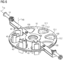
- FIGURE 6 shows an embodiment of a cable support arrangement 1 according to the invention comprising multiple self-clamping cable guards 40 according to FIGURE 5 .
- the cable support arrangement 1 is shown with one cable bundle guide 10 having multiple, in this case eight, through-openings 100.
- the cable bundle guide 10 is provided as a circular plate having the through-openings 100 arranged around its center point.
- the through-openings 100 have a triangular shape corresponding to the triangular shape of the power cable bundles 30B.
- the cable support arrangement 1 may comprise multiple cable bundle guides 10 arranged at a distance from one another although only one is shown.
- the cable bundle guide 10 is tiltable with respect to a tilting axis T 10 perpendicular to the central longitudinal axis L 40 of the multiple self-clamping cable guards 40 by means of a tilting mechanism 14.
- Each one of the multiple self-clamping cable guards 40 is shown to be inserted into each one of the multiple through-openings 100.
- the power cables 30 are omitted in this illustration.
- the wear protection surfaces 49.1, 49.2, 49.3 are arranged parallel to straight edges 12.1, 12.2, 12.3 of the through-openings 100.
- the corners 13.1, 13.2, 13.3 of the triangular shape of the through-openings 100 are provided with clearance with respect to the power cables 30 such that they are not subjected to wear.
Landscapes
- Engineering & Computer Science (AREA)
- General Engineering & Computer Science (AREA)
- Mechanical Engineering (AREA)
- Life Sciences & Earth Sciences (AREA)
- Sustainable Development (AREA)
- Sustainable Energy (AREA)
- Chemical & Material Sciences (AREA)
- Combustion & Propulsion (AREA)
- Wind Motors (AREA)
Claims (13)
- Selbstklemmender Kabelschutz (40) zum Klemmen von Stromkabeln (30) eines Stromkabelbündels (30B) einer Kabelträgeranordnung (1) in einer Windturbine (5),wobei der selbstklemmende Kabelschutz (40) drei um eine Mittellängsachse (L40) des selbstklemmenden Kabelschutzes (40) angeordnete Ausnehmungen (42) zum formschlüssigen Klemmen eines Stromkabels (30) des Stromkabelbündels (30B) innerhalb jeder der drei Ausnehmungen (46) umfasst, undwobei der selbstklemmende Kabelschutz (40) drei um die Mittellängsachse (L40) angeordnete Verschleißschutzplatten (45) umfasst,wobei jede der drei Ausnehmungen (46) eine offene Seite (47) zum Einführen eines jeweiligen Stromkabels (30) des Stromkabelbündels (30B) darin umfasst,wobei jede der offenen Seiten (47) einer der drei Ausnehmungen (46) jeweils durch zwei der drei Verschleißschutzplatten (45) begrenzt wird, um die in den Ausnehmungen (46) eingeklemmten Stromkabel (30) vor Verschleiß zu schützen.
- Selbstklemmender Kabelschutz (40) gemäß Anspruch 1, wobei der selbstklemmende Kabelschutz (40) aus einem elastischen und/oder flexiblen Material so hergestellt ist, dass die Ausnehmungen (46) zur Aufnahme der Stromkabel (30) elastisch aufgeweitet und zum Klemmen der Stromkabel (30) elastisch zurückgestellt werden können.
- Selbstklemmender Kabelschutz (40) gemäß Anspruch 1 oder 2, wobei der selbstklemmende Kabelschutz (40) einen mittleren Abschnitt (41) aufweist, wobei der mittlere Abschluss (41) einen mit der Mittellängsachse (L40) kongruenten Mittelpunkt aufweist und der mittlere Abschnitt (41) die Form eines kreisförmigen Dreiecks mit konkaven Kreisbogenkanten (42) umfasst.
- Selbstklemmender Kabelschutz (40) gemäß Anspruch 3, wobei der selbstklemmende Kabelschutz (40) drei äußere Abschnitte (43) umfasst, die sich von dem mittleren Abschnitt (41) nach außen erstrecken, wobei jeder der äußeren Abschnitte (43) an einem Scheitelteil (48) der kreisförmigen Dreiecksform des mittleren Abschnitts (41) befestigt ist.
- Selbstklemmender Kabelschutz (40) gemäß Anspruch 4, wobei jeder der äußeren Abschnitte (43) die Form eines kreisförmigen Dreiecks mit zwei konkaven Kreisbogenkanten (44) und einer geraden Kante (49) aufweist, wobei die gerade Kante (49) eine Verschleißschutzfläche (49) einer der drei Verschleißschutzplatten (45) ist.
- Selbstklemmender Kabelschutz (40) gemäß einem der vorhergehenden Ansprüche, wobei die Verschleißschutzplatten (45) mit einem imaginären Dreieck kongruent sind, wobei das imaginäre Dreieck einen Mittelpunkt hat, der mit der Mittellängsachse (L40) kongruent ist und den selbstklemmenden Kabelschutz (40) umgrenzt.
- Selbstklemmender Kabelschutz (40) gemäß einem der vorhergehenden Ansprüche, wobei der selbstklemmende Kabelschutz (40) monolithisch ausgebildet ist.
- Selbstklemmender Kabelschutz (40) gemäß einem der vorhergehenden Ansprüche, wobei der selbstklemmende Kabelschutz (40) spritzgegossen ist.
- Kabelträgeranordnung (1) für eine Windturbine (5), umfassend:mehrere selbstklemmende Kabelschutzvorrichtungen (40) gemäß einem der vorhergehenden Ansprüche,wobei die Kabelträgeranordnung (1) mindestens eine Kabelbündelführung (10) und mehrere Stromkabelbündel (30B) umfasst,jedes Stromkabelbündel (30B) aus drei Stromkabeln (30) besteht, undwobei jede der mehreren selbstklemmenden Kabelschutzvorrichtungen (40) in jeder ihrer drei Ausnehmungen (46) eines der drei Stromkabel (40) jedes der mehreren Stromkabelbündel (30B) einklemmt, undwobei jede der mehreren selbstklemmenden Kabelschutzvorrichtungen (40) mit den darin eingeklemmten Stromkabeln (30) in einer von mehreren Durchgangsöffnungen (100) innerhalb der mindestens einen Kabelbündelführung (10) angeordnet ist.
- Kabelträgeranordnung (1) gemäß Anspruch 9, wobei die mehreren Durchgangsöffnungen (100) innerhalb der mindestens einen Kabelbündelführung (10) eine Dreiecksform mit geraden Kanten (12) aufweisen und die Verschleißschutzplatten (45) der selbstklemmenden Kabelschutzvorrichtungen (40) parallel zu den geraden Kanten (12) der Dreiecksform der Durchgangsöffnungen (100) angeordnet sind.
- Kabelträgeranordnung (1) gemäß Anspruch 9 oder 10, wobei die mindestens eine Kabelbündelführung (10) einen Kippmechanismus (14) zum Kippen der Kabelbündelführung (10) um eine Kippachse (T10) rechtwinklig zur Mittellängsachse (L40) der mehrfachen selbstklemmenden Kabelabdeckungen (40) umfasst.
- Kabelträgeranordnung (1) gemäß einem der Ansprüche 9 bis 11, wobei die mindestens eine Kabelbündelführung (10) eine kreisförmige Platte ist und die mehreren Durchgangsöffnungen (100) um einen Mittelpunkt der kreisförmigen, ebenen Platte angeordnet sind.
- Windturbine (5), umfassend eine Gondel (4), die auf einem Turm (2) der Windturbine (5) montiert ist, einem in der Gondel (4) angeordneten Generator (3) zur Stromerzeugung und mindestens einen selbstklemmenden Kabelschutz (40) gemäß einem der Ansprüche 1 bis 8 oder einer Kabelträgeranordnung (1) gemäß einem der Ansprüche 9 bis 12.
Applications Claiming Priority (2)
| Application Number | Priority Date | Filing Date | Title |
|---|---|---|---|
| EP20157253.4A EP3865707A1 (de) | 2020-02-13 | 2020-02-13 | Selbstklemmender kabelschutz zum klemmen von stromkabeln eines stromkabelbündels einer kabelhalteranordnung in einer windturbine, kabelhalter und windturbine |
| PCT/EP2021/052753 WO2021160527A1 (en) | 2020-02-13 | 2021-02-05 | Self-clamping cable guard for clamping power cables of a power cable bundle of a cable support arrangement in a wind turbine, cable support arrangement and wind turbine |
Publications (2)
| Publication Number | Publication Date |
|---|---|
| EP4077935A1 EP4077935A1 (de) | 2022-10-26 |
| EP4077935B1 true EP4077935B1 (de) | 2023-09-27 |
Family
ID=69591567
Family Applications (2)
| Application Number | Title | Priority Date | Filing Date |
|---|---|---|---|
| EP20157253.4A Withdrawn EP3865707A1 (de) | 2020-02-13 | 2020-02-13 | Selbstklemmender kabelschutz zum klemmen von stromkabeln eines stromkabelbündels einer kabelhalteranordnung in einer windturbine, kabelhalter und windturbine |
| EP21707621.5A Active EP4077935B1 (de) | 2020-02-13 | 2021-02-05 | Selbstklemmender kabelschutz zum klemmen von stromkabeln eines stromkabelbündels einer kabelhalteranordnung in einer windturbine, kabelhalter und windturbine |
Family Applications Before (1)
| Application Number | Title | Priority Date | Filing Date |
|---|---|---|---|
| EP20157253.4A Withdrawn EP3865707A1 (de) | 2020-02-13 | 2020-02-13 | Selbstklemmender kabelschutz zum klemmen von stromkabeln eines stromkabelbündels einer kabelhalteranordnung in einer windturbine, kabelhalter und windturbine |
Country Status (6)
| Country | Link |
|---|---|
| US (1) | US12215675B2 (de) |
| EP (2) | EP3865707A1 (de) |
| CN (1) | CN115038866B (de) |
| BR (1) | BR112022014850A2 (de) |
| DK (1) | DK4077935T3 (de) |
| WO (1) | WO2021160527A1 (de) |
Families Citing this family (4)
| Publication number | Priority date | Publication date | Assignee | Title |
|---|---|---|---|---|
| EP3761469A1 (de) * | 2019-07-02 | 2021-01-06 | Vestas Wind Systems A/S | Montage von stromkabeln zur begrenzung von gleichtaktströmen |
| CN113833608B (zh) * | 2021-10-20 | 2026-03-03 | 北京华能新锐控制技术有限公司 | 风力发电设备 |
| EP4632973A1 (de) * | 2024-04-09 | 2025-10-15 | Fundación Tecnalia Research & Innovation | Schutz und verfahren zum schutz eines teils eines kabels |
| CN118630662B (zh) * | 2024-08-15 | 2024-12-13 | 华能陇东能源有限责任公司 | 一种扭缆保护装置及使用方法 |
Family Cites Families (17)
| Publication number | Priority date | Publication date | Assignee | Title |
|---|---|---|---|---|
| US3092360A (en) * | 1962-02-08 | 1963-06-04 | Boeing Co | Positive locking fairlead for electrical cables |
| EP1149449A2 (de) * | 1998-12-17 | 2001-10-31 | Dan-Control Engineering A/S | Windkraftanlage mit kabelhalterung , kabelhalterung und halterungstraggestelldafür. |
| US6710249B1 (en) * | 2002-09-13 | 2004-03-23 | Sandra L. Denton | Wire separator |
| DE102008046658B4 (de) * | 2008-09-10 | 2012-08-30 | Phoenix Contact Gmbh & Co. Kg | Kabeldurchführung |
| ES2443121T3 (es) * | 2008-09-30 | 2014-02-17 | Toshiba Mitsubishi-Electric Industrial Systems Corporation | Soporte para cables y estructura de haces de cables |
| WO2010108538A1 (en) * | 2009-03-24 | 2010-09-30 | Amsc Windtec Gmbh | Development of a new tower cabling |
| ES2601779T3 (es) * | 2010-06-03 | 2017-02-16 | Ae Rotor Holding B.V. | Torre para una turbina eólica |
| DE102010032687A1 (de) * | 2010-07-29 | 2012-02-02 | Hydac Accessories Gmbh | Befestigungssystem für Kabel, insbesondere bei Windkraftanlagen |
| GB201200915D0 (en) * | 2012-01-19 | 2012-02-29 | Airbus Operations Ltd | Cable retainer |
| DE102012001408A1 (de) * | 2012-01-25 | 2013-07-25 | Hydac Accessories Gmbh | Befestigungssystem |
| DE102012019490A1 (de) * | 2012-10-04 | 2014-04-10 | Hydac Accessories Gmbh | System zur Führung und Lagesicherung von Strangelementen |
| KR102078997B1 (ko) * | 2012-10-04 | 2020-02-19 | 하이닥 악세서리즈 게엠베하 | 풍력 터빈에서 케이블을 라우팅하기 위한 장치 |
| EP2918828B1 (de) * | 2014-03-11 | 2023-07-26 | Siemens Gamesa Renewable Energy A/S | Kabelhalteranordnung |
| JP6200454B2 (ja) * | 2015-06-12 | 2017-09-20 | 矢崎総業株式会社 | ワイヤーハーネス |
| CN106816840B (zh) * | 2017-03-28 | 2018-08-14 | 北京金风科创风电设备有限公司 | 扭缆保护装置、扭缆保护装置的使用方法及风力发电机组 |
| CN108757352B (zh) * | 2018-05-22 | 2019-10-15 | 江苏金风科技有限公司 | 电缆保护装置及风力发电机组 |
| US20220390042A1 (en) * | 2021-06-03 | 2022-12-08 | R.A. Phillips Industries, Inc. | Conduit management device |
-
2020
- 2020-02-13 EP EP20157253.4A patent/EP3865707A1/de not_active Withdrawn
-
2021
- 2021-02-05 US US17/796,697 patent/US12215675B2/en active Active
- 2021-02-05 BR BR112022014850A patent/BR112022014850A2/pt active IP Right Grant
- 2021-02-05 EP EP21707621.5A patent/EP4077935B1/de active Active
- 2021-02-05 WO PCT/EP2021/052753 patent/WO2021160527A1/en not_active Ceased
- 2021-02-05 CN CN202180014478.8A patent/CN115038866B/zh active Active
- 2021-02-05 DK DK21707621.5T patent/DK4077935T3/da active
Also Published As
| Publication number | Publication date |
|---|---|
| EP4077935A1 (de) | 2022-10-26 |
| DK4077935T3 (da) | 2023-12-04 |
| EP3865707A1 (de) | 2021-08-18 |
| CN115038866A (zh) | 2022-09-09 |
| BR112022014850A2 (pt) | 2022-09-20 |
| WO2021160527A1 (en) | 2021-08-19 |
| US20230340946A1 (en) | 2023-10-26 |
| CN115038866B (zh) | 2025-08-05 |
| US12215675B2 (en) | 2025-02-04 |
Similar Documents
| Publication | Publication Date | Title |
|---|---|---|
| US12215675B2 (en) | Self-clamping cable guard for clamping power cables of a power cable bundle of a cable support arrangement in a wind turbine, cable support arrangement and wind turbine | |
| EP2918828B1 (de) | Kabelhalteranordnung | |
| ES2898897T3 (es) | Dispositivo de protección de cables y grupo de generador de energía eólica | |
| DK2577058T3 (en) | Tower of a wind turbine | |
| US8227695B2 (en) | Cable holding structure for wind turbine generator | |
| US9051920B2 (en) | Development of a new tower cabling | |
| US9190823B2 (en) | Wind energy plant having a twistable nacelle cable guide | |
| JP2008298051A (ja) | 風力発電装置 | |
| EP2510149B1 (de) | SEIL MIT EINGESPLEISSTER ÖSE und ZUGEHÖRIGES VERFAHREN ZUR HERSTELLUNG EINER ÖSE | |
| CN1244310A (zh) | 交流电机 | |
| JP2014185637A (ja) | 風力タービンタワーにおいてケーブル離間プレートを回転させるためのユニット | |
| CA2762978C (en) | Stator element for an electrical machine | |
| KR100514633B1 (ko) | 고·저압 전동기 회전자 인출 및 삽입 장치 | |
| CN208386092U (zh) | 一种电缆线防断保护装置 | |
| EP3322894B1 (de) | Kabelführung für windturbinensystem mit mehreren rotoren | |
| CN109980828B (zh) | 定子和电动机 | |
| CN220273246U (zh) | 一种新型电缆护套端罩 | |
| EP0646817A2 (de) | Kompositkabelverbinder | |
| CN109980826B (zh) | 定子和电动机 | |
| KR20200000142U (ko) | 전선용 스톡브리지 댐퍼 | |
| CN222484158U (zh) | 一种电缆悬吊与扭转装置及风力发电机组 | |
| CA2230206A1 (en) | Method for installing a telecommunication cable on a supporting cable and arrangement produced thereby | |
| CN215118353U (zh) | 一种绝缘密封的柔性电缆 | |
| JP2019062707A (ja) | 鳥害防止具 | |
| JPS61193305A (ja) | 平型エレベ−タケ−ブル |
Legal Events
| Date | Code | Title | Description |
|---|---|---|---|
| STAA | Information on the status of an ep patent application or granted ep patent |
Free format text: STATUS: UNKNOWN |
|
| STAA | Information on the status of an ep patent application or granted ep patent |
Free format text: STATUS: THE INTERNATIONAL PUBLICATION HAS BEEN MADE |
|
| PUAI | Public reference made under article 153(3) epc to a published international application that has entered the european phase |
Free format text: ORIGINAL CODE: 0009012 |
|
| STAA | Information on the status of an ep patent application or granted ep patent |
Free format text: STATUS: REQUEST FOR EXAMINATION WAS MADE |
|
| 17P | Request for examination filed |
Effective date: 20220721 |
|
| AK | Designated contracting states |
Kind code of ref document: A1 Designated state(s): AL AT BE BG CH CY CZ DE DK EE ES FI FR GB GR HR HU IE IS IT LI LT LU LV MC MK MT NL NO PL PT RO RS SE SI SK SM TR |
|
| DAV | Request for validation of the european patent (deleted) | ||
| DAX | Request for extension of the european patent (deleted) | ||
| GRAP | Despatch of communication of intention to grant a patent |
Free format text: ORIGINAL CODE: EPIDOSNIGR1 |
|
| STAA | Information on the status of an ep patent application or granted ep patent |
Free format text: STATUS: GRANT OF PATENT IS INTENDED |
|
| INTG | Intention to grant announced |
Effective date: 20230524 |
|
| GRAS | Grant fee paid |
Free format text: ORIGINAL CODE: EPIDOSNIGR3 |
|
| GRAA | (expected) grant |
Free format text: ORIGINAL CODE: 0009210 |
|
| STAA | Information on the status of an ep patent application or granted ep patent |
Free format text: STATUS: THE PATENT HAS BEEN GRANTED |
|
| AK | Designated contracting states |
Kind code of ref document: B1 Designated state(s): AL AT BE BG CH CY CZ DE DK EE ES FI FR GB GR HR HU IE IS IT LI LT LU LV MC MK MT NL NO PL PT RO RS SE SI SK SM TR |
|
| REG | Reference to a national code |
Ref country code: GB Ref legal event code: FG4D |
|
| REG | Reference to a national code |
Ref country code: CH Ref legal event code: EP |
|
| REG | Reference to a national code |
Ref country code: DE Ref legal event code: R096 Ref document number: 602021005469 Country of ref document: DE |
|
| REG | Reference to a national code |
Ref country code: IE Ref legal event code: FG4D |
|
| REG | Reference to a national code |
Ref country code: DK Ref legal event code: T3 Effective date: 20231201 |
|
| REG | Reference to a national code |
Ref country code: LT Ref legal event code: MG9D |
|
| PG25 | Lapsed in a contracting state [announced via postgrant information from national office to epo] |
Ref country code: GR Free format text: LAPSE BECAUSE OF FAILURE TO SUBMIT A TRANSLATION OF THE DESCRIPTION OR TO PAY THE FEE WITHIN THE PRESCRIBED TIME-LIMIT Effective date: 20231228 |
|
| PG25 | Lapsed in a contracting state [announced via postgrant information from national office to epo] |
Ref country code: SE Free format text: LAPSE BECAUSE OF FAILURE TO SUBMIT A TRANSLATION OF THE DESCRIPTION OR TO PAY THE FEE WITHIN THE PRESCRIBED TIME-LIMIT Effective date: 20230927 Ref country code: RS Free format text: LAPSE BECAUSE OF FAILURE TO SUBMIT A TRANSLATION OF THE DESCRIPTION OR TO PAY THE FEE WITHIN THE PRESCRIBED TIME-LIMIT Effective date: 20230927 Ref country code: NO Free format text: LAPSE BECAUSE OF FAILURE TO SUBMIT A TRANSLATION OF THE DESCRIPTION OR TO PAY THE FEE WITHIN THE PRESCRIBED TIME-LIMIT Effective date: 20231227 Ref country code: LV Free format text: LAPSE BECAUSE OF FAILURE TO SUBMIT A TRANSLATION OF THE DESCRIPTION OR TO PAY THE FEE WITHIN THE PRESCRIBED TIME-LIMIT Effective date: 20230927 Ref country code: LT Free format text: LAPSE BECAUSE OF FAILURE TO SUBMIT A TRANSLATION OF THE DESCRIPTION OR TO PAY THE FEE WITHIN THE PRESCRIBED TIME-LIMIT Effective date: 20230927 Ref country code: HR Free format text: LAPSE BECAUSE OF FAILURE TO SUBMIT A TRANSLATION OF THE DESCRIPTION OR TO PAY THE FEE WITHIN THE PRESCRIBED TIME-LIMIT Effective date: 20230927 Ref country code: GR Free format text: LAPSE BECAUSE OF FAILURE TO SUBMIT A TRANSLATION OF THE DESCRIPTION OR TO PAY THE FEE WITHIN THE PRESCRIBED TIME-LIMIT Effective date: 20231228 Ref country code: FI Free format text: LAPSE BECAUSE OF FAILURE TO SUBMIT A TRANSLATION OF THE DESCRIPTION OR TO PAY THE FEE WITHIN THE PRESCRIBED TIME-LIMIT Effective date: 20230927 |
|
| REG | Reference to a national code |
Ref country code: NL Ref legal event code: MP Effective date: 20230927 |
|
| REG | Reference to a national code |
Ref country code: AT Ref legal event code: MK05 Ref document number: 1615665 Country of ref document: AT Kind code of ref document: T Effective date: 20230927 |
|
| PG25 | Lapsed in a contracting state [announced via postgrant information from national office to epo] |
Ref country code: NL Free format text: LAPSE BECAUSE OF FAILURE TO SUBMIT A TRANSLATION OF THE DESCRIPTION OR TO PAY THE FEE WITHIN THE PRESCRIBED TIME-LIMIT Effective date: 20230927 |
|
| PG25 | Lapsed in a contracting state [announced via postgrant information from national office to epo] |
Ref country code: IS Free format text: LAPSE BECAUSE OF FAILURE TO SUBMIT A TRANSLATION OF THE DESCRIPTION OR TO PAY THE FEE WITHIN THE PRESCRIBED TIME-LIMIT Effective date: 20240127 |
|
| PG25 | Lapsed in a contracting state [announced via postgrant information from national office to epo] |
Ref country code: AT Free format text: LAPSE BECAUSE OF FAILURE TO SUBMIT A TRANSLATION OF THE DESCRIPTION OR TO PAY THE FEE WITHIN THE PRESCRIBED TIME-LIMIT Effective date: 20230927 |
|
| PG25 | Lapsed in a contracting state [announced via postgrant information from national office to epo] |
Ref country code: ES Free format text: LAPSE BECAUSE OF FAILURE TO SUBMIT A TRANSLATION OF THE DESCRIPTION OR TO PAY THE FEE WITHIN THE PRESCRIBED TIME-LIMIT Effective date: 20230927 |
|
| PG25 | Lapsed in a contracting state [announced via postgrant information from national office to epo] |
Ref country code: SM Free format text: LAPSE BECAUSE OF FAILURE TO SUBMIT A TRANSLATION OF THE DESCRIPTION OR TO PAY THE FEE WITHIN THE PRESCRIBED TIME-LIMIT Effective date: 20230927 Ref country code: RO Free format text: LAPSE BECAUSE OF FAILURE TO SUBMIT A TRANSLATION OF THE DESCRIPTION OR TO PAY THE FEE WITHIN THE PRESCRIBED TIME-LIMIT Effective date: 20230927 Ref country code: IS Free format text: LAPSE BECAUSE OF FAILURE TO SUBMIT A TRANSLATION OF THE DESCRIPTION OR TO PAY THE FEE WITHIN THE PRESCRIBED TIME-LIMIT Effective date: 20240127 Ref country code: ES Free format text: LAPSE BECAUSE OF FAILURE TO SUBMIT A TRANSLATION OF THE DESCRIPTION OR TO PAY THE FEE WITHIN THE PRESCRIBED TIME-LIMIT Effective date: 20230927 Ref country code: EE Free format text: LAPSE BECAUSE OF FAILURE TO SUBMIT A TRANSLATION OF THE DESCRIPTION OR TO PAY THE FEE WITHIN THE PRESCRIBED TIME-LIMIT Effective date: 20230927 Ref country code: CZ Free format text: LAPSE BECAUSE OF FAILURE TO SUBMIT A TRANSLATION OF THE DESCRIPTION OR TO PAY THE FEE WITHIN THE PRESCRIBED TIME-LIMIT Effective date: 20230927 Ref country code: AT Free format text: LAPSE BECAUSE OF FAILURE TO SUBMIT A TRANSLATION OF THE DESCRIPTION OR TO PAY THE FEE WITHIN THE PRESCRIBED TIME-LIMIT Effective date: 20230927 Ref country code: PT Free format text: LAPSE BECAUSE OF FAILURE TO SUBMIT A TRANSLATION OF THE DESCRIPTION OR TO PAY THE FEE WITHIN THE PRESCRIBED TIME-LIMIT Effective date: 20240129 Ref country code: SK Free format text: LAPSE BECAUSE OF FAILURE TO SUBMIT A TRANSLATION OF THE DESCRIPTION OR TO PAY THE FEE WITHIN THE PRESCRIBED TIME-LIMIT Effective date: 20230927 |
|
| PG25 | Lapsed in a contracting state [announced via postgrant information from national office to epo] |
Ref country code: PL Free format text: LAPSE BECAUSE OF FAILURE TO SUBMIT A TRANSLATION OF THE DESCRIPTION OR TO PAY THE FEE WITHIN THE PRESCRIBED TIME-LIMIT Effective date: 20230927 Ref country code: IT Free format text: LAPSE BECAUSE OF FAILURE TO SUBMIT A TRANSLATION OF THE DESCRIPTION OR TO PAY THE FEE WITHIN THE PRESCRIBED TIME-LIMIT Effective date: 20230927 |
|
| REG | Reference to a national code |
Ref country code: DE Ref legal event code: R097 Ref document number: 602021005469 Country of ref document: DE |
|
| PLBE | No opposition filed within time limit |
Free format text: ORIGINAL CODE: 0009261 |
|
| STAA | Information on the status of an ep patent application or granted ep patent |
Free format text: STATUS: NO OPPOSITION FILED WITHIN TIME LIMIT |
|
| 26N | No opposition filed |
Effective date: 20240628 |
|
| PG25 | Lapsed in a contracting state [announced via postgrant information from national office to epo] |
Ref country code: MC Free format text: LAPSE BECAUSE OF FAILURE TO SUBMIT A TRANSLATION OF THE DESCRIPTION OR TO PAY THE FEE WITHIN THE PRESCRIBED TIME-LIMIT Effective date: 20230927 |
|
| REG | Reference to a national code |
Ref country code: CH Ref legal event code: PL |
|
| PG25 | Lapsed in a contracting state [announced via postgrant information from national office to epo] |
Ref country code: LU Free format text: LAPSE BECAUSE OF NON-PAYMENT OF DUE FEES Effective date: 20240205 |
|
| PG25 | Lapsed in a contracting state [announced via postgrant information from national office to epo] |
Ref country code: CH Free format text: LAPSE BECAUSE OF NON-PAYMENT OF DUE FEES Effective date: 20240229 |
|
| PG25 | Lapsed in a contracting state [announced via postgrant information from national office to epo] |
Ref country code: SI Free format text: LAPSE BECAUSE OF FAILURE TO SUBMIT A TRANSLATION OF THE DESCRIPTION OR TO PAY THE FEE WITHIN THE PRESCRIBED TIME-LIMIT Effective date: 20230927 |
|
| PG25 | Lapsed in a contracting state [announced via postgrant information from national office to epo] |
Ref country code: SI Free format text: LAPSE BECAUSE OF FAILURE TO SUBMIT A TRANSLATION OF THE DESCRIPTION OR TO PAY THE FEE WITHIN THE PRESCRIBED TIME-LIMIT Effective date: 20230927 Ref country code: LU Free format text: LAPSE BECAUSE OF NON-PAYMENT OF DUE FEES Effective date: 20240205 Ref country code: CH Free format text: LAPSE BECAUSE OF NON-PAYMENT OF DUE FEES Effective date: 20240229 |
|
| PG25 | Lapsed in a contracting state [announced via postgrant information from national office to epo] |
Ref country code: BG Free format text: LAPSE BECAUSE OF FAILURE TO SUBMIT A TRANSLATION OF THE DESCRIPTION OR TO PAY THE FEE WITHIN THE PRESCRIBED TIME-LIMIT Effective date: 20230927 |
|
| PG25 | Lapsed in a contracting state [announced via postgrant information from national office to epo] |
Ref country code: BG Free format text: LAPSE BECAUSE OF FAILURE TO SUBMIT A TRANSLATION OF THE DESCRIPTION OR TO PAY THE FEE WITHIN THE PRESCRIBED TIME-LIMIT Effective date: 20230927 |
|
| REG | Reference to a national code |
Ref country code: BE Ref legal event code: MM Effective date: 20240229 |
|
| PG25 | Lapsed in a contracting state [announced via postgrant information from national office to epo] |
Ref country code: BE Free format text: LAPSE BECAUSE OF NON-PAYMENT OF DUE FEES Effective date: 20240229 |
|
| PG25 | Lapsed in a contracting state [announced via postgrant information from national office to epo] |
Ref country code: IE Free format text: LAPSE BECAUSE OF NON-PAYMENT OF DUE FEES Effective date: 20240205 |
|
| PG25 | Lapsed in a contracting state [announced via postgrant information from national office to epo] |
Ref country code: IE Free format text: LAPSE BECAUSE OF NON-PAYMENT OF DUE FEES Effective date: 20240205 Ref country code: BE Free format text: LAPSE BECAUSE OF NON-PAYMENT OF DUE FEES Effective date: 20240229 |
|
| PG25 | Lapsed in a contracting state [announced via postgrant information from national office to epo] |
Ref country code: CY Free format text: LAPSE BECAUSE OF FAILURE TO SUBMIT A TRANSLATION OF THE DESCRIPTION OR TO PAY THE FEE WITHIN THE PRESCRIBED TIME-LIMIT; INVALID AB INITIO Effective date: 20210205 |
|
| PG25 | Lapsed in a contracting state [announced via postgrant information from national office to epo] |
Ref country code: HU Free format text: LAPSE BECAUSE OF FAILURE TO SUBMIT A TRANSLATION OF THE DESCRIPTION OR TO PAY THE FEE WITHIN THE PRESCRIBED TIME-LIMIT; INVALID AB INITIO Effective date: 20210205 |
|
| PG25 | Lapsed in a contracting state [announced via postgrant information from national office to epo] |
Ref country code: TR Free format text: LAPSE BECAUSE OF FAILURE TO SUBMIT A TRANSLATION OF THE DESCRIPTION OR TO PAY THE FEE WITHIN THE PRESCRIBED TIME-LIMIT Effective date: 20230927 |
|
| PGFP | Annual fee paid to national office [announced via postgrant information from national office to epo] |
Ref country code: GB Payment date: 20260223 Year of fee payment: 6 |
|
| PGFP | Annual fee paid to national office [announced via postgrant information from national office to epo] |
Ref country code: DK Payment date: 20260223 Year of fee payment: 6 Ref country code: DE Payment date: 20250829 Year of fee payment: 6 |
|
| PGFP | Annual fee paid to national office [announced via postgrant information from national office to epo] |
Ref country code: FR Payment date: 20260224 Year of fee payment: 6 |