EP4077146B1 - Verbesserungen bei bandgetriebener verpackung - Google Patents
Verbesserungen bei bandgetriebener verpackung Download PDFInfo
- Publication number
- EP4077146B1 EP4077146B1 EP20845686.3A EP20845686A EP4077146B1 EP 4077146 B1 EP4077146 B1 EP 4077146B1 EP 20845686 A EP20845686 A EP 20845686A EP 4077146 B1 EP4077146 B1 EP 4077146B1
- Authority
- EP
- European Patent Office
- Prior art keywords
- band
- region
- panel
- sleeve
- package
- Prior art date
- Legal status (The legal status is an assumption and is not a legal conclusion. Google has not performed a legal analysis and makes no representation as to the accuracy of the status listed.)
- Active
Links
Images


Classifications
-
- B—PERFORMING OPERATIONS; TRANSPORTING
- B31—MAKING ARTICLES OF PAPER, CARDBOARD OR MATERIAL WORKED IN A MANNER ANALOGOUS TO PAPER; WORKING PAPER, CARDBOARD OR MATERIAL WORKED IN A MANNER ANALOGOUS TO PAPER
- B31B—MAKING CONTAINERS OF PAPER, CARDBOARD OR MATERIAL WORKED IN A MANNER ANALOGOUS TO PAPER
- B31B50/00—Making rigid or semi-rigid containers, e.g. boxes or cartons
- B31B50/60—Uniting opposed surfaces or edges; Taping
- B31B50/62—Uniting opposed surfaces or edges; Taping by adhesives
- B31B50/624—Applying glue on blanks
-
- B—PERFORMING OPERATIONS; TRANSPORTING
- B65—CONVEYING; PACKING; STORING; HANDLING THIN OR FILAMENTARY MATERIAL
- B65D—CONTAINERS FOR STORAGE OR TRANSPORT OF ARTICLES OR MATERIALS, e.g. BAGS, BARRELS, BOTTLES, BOXES, CANS, CARTONS, CRATES, DRUMS, JARS, TANKS, HOPPERS, FORWARDING CONTAINERS; ACCESSORIES, CLOSURES, OR FITTINGS THEREFOR; PACKAGING ELEMENTS; PACKAGES
- B65D5/00—Rigid or semi-rigid containers of polygonal cross-section, e.g. boxes, cartons or trays, formed by folding or erecting one or more blanks made of paper
- B65D5/38—Drawer-and-shell type containers
-
- B—PERFORMING OPERATIONS; TRANSPORTING
- B65—CONVEYING; PACKING; STORING; HANDLING THIN OR FILAMENTARY MATERIAL
- B65D—CONTAINERS FOR STORAGE OR TRANSPORT OF ARTICLES OR MATERIALS, e.g. BAGS, BARRELS, BOTTLES, BOXES, CANS, CARTONS, CRATES, DRUMS, JARS, TANKS, HOPPERS, FORWARDING CONTAINERS; ACCESSORIES, CLOSURES, OR FITTINGS THEREFOR; PACKAGING ELEMENTS; PACKAGES
- B65D5/00—Rigid or semi-rigid containers of polygonal cross-section, e.g. boxes, cartons or trays, formed by folding or erecting one or more blanks made of paper
- B65D5/42—Details of containers or of foldable or erectable container blanks
- B65D5/64—Lids
- B65D5/66—Hinged lids
- B65D5/6602—Hinged lids formed by folding one or more extensions hinged to the upper edge of a tubular container body
- B65D5/6617—Hinged lids formed by folding one or more extensions hinged to the upper edge of a tubular container body the container body sliding in an outer sleeve
-
- B—PERFORMING OPERATIONS; TRANSPORTING
- B65—CONVEYING; PACKING; STORING; HANDLING THIN OR FILAMENTARY MATERIAL
- B65D—CONTAINERS FOR STORAGE OR TRANSPORT OF ARTICLES OR MATERIALS, e.g. BAGS, BARRELS, BOTTLES, BOXES, CANS, CARTONS, CRATES, DRUMS, JARS, TANKS, HOPPERS, FORWARDING CONTAINERS; ACCESSORIES, CLOSURES, OR FITTINGS THEREFOR; PACKAGING ELEMENTS; PACKAGES
- B65D5/00—Rigid or semi-rigid containers of polygonal cross-section, e.g. boxes, cartons or trays, formed by folding or erecting one or more blanks made of paper
- B65D5/42—Details of containers or of foldable or erectable container blanks
- B65D5/72—Contents-dispensing means
- B65D5/728—Contents-dispensing means for drawer-and-shell-type containers
-
- B—PERFORMING OPERATIONS; TRANSPORTING
- B31—MAKING ARTICLES OF PAPER, CARDBOARD OR MATERIAL WORKED IN A MANNER ANALOGOUS TO PAPER; WORKING PAPER, CARDBOARD OR MATERIAL WORKED IN A MANNER ANALOGOUS TO PAPER
- B31B—MAKING CONTAINERS OF PAPER, CARDBOARD OR MATERIAL WORKED IN A MANNER ANALOGOUS TO PAPER
- B31B2120/00—Construction of rigid or semi-rigid containers
- B31B2120/60—Construction of rigid or semi-rigid containers of drawer-and-shell type
Definitions
- This invention relates to a package insert, to a package and to a method of assembling a package.
- Packages including packages for containing articles and packages for containing information or other display items are frequently used as one-use disposable items, which has environmental implications. It is desirable to recycle such packages as much as possible.
- packages can be made of mixed materials that would come under different recycling categories. Such packages cannot be recycled as a single unit, but must be recycled as separate components. This is the case, for example, with band-driven package, which commonly feature of band of plastics materials used to drive components made of other non-plastics materials, such a cardboard.
- Band driven packages comprise a sleeve that is divided into two compartments by a divider. Structural rigidity of the two compartments is desirable to protect the contents of the package. This can be achieved by using a rigid or at least relatively stiff material for the components. However, such rigid or stiff material may be particularly difficult to break apart for recycling purposes.
- WO 2010/015638 A1 describes a package formed by a sleeve, first and second members slideably mounted within said sleeve and a connecting mechanism operatively connecting the members.
- WO 2007/007094 A1 describes a package comprising first and second tab members which lie substantially on the same plane as each other, and a means for driving the movement of one of the tab members.
- the drive means comprises belt means with which the first and second tab members co-operate such that when the first tab member is moved in a first direction said second tab member is caused to move in a second direction opposite to said first direction.
- US 2008/156686 A1 describes a product delivery and/or dispensing system which is realised by providing a housing or holding zone constructed for retaining a product or item which a user or gift-giver wishes to be delivered or dispensed.
- the housing or holding zone may be automatically activated or moved from a first, fully retained position into a second, outwardly extending position whenever a slider panel is moved in a direction which is opposite from the direction of the movement of the housing or holding zone.
- US 2014/216982 A1 describes a package comprising an inner sliding piece assembled inside of one or more outer sleeves.
- the inner sliding piece may contain a gift card, loyalty card, product, or promotional messages, and the card, product or messages can be revealed by pulling the inner sliding piece at least partially out of the outer sleeve.
- a package insert comprising first and second members and a band.
- the first and second members are coupled to the band, such that movement of the first member in a first direction drives the band to cause movement of the second member in a second direction.
- the first member comprises a primary region and an attachment region that is configured to detachably couple the primary region to the band.
- the attachment region may be configured to be detachable from the band so that the attachment region and the primary region are detachable form the band.
- the attachment region is configured to be detachable from the primary region so as to decouple the primary region from the band and the attachment region.
- the first member may be movable between a closed configuration in which the first member has been displaced in the first direction to a minimum possible extent, and an open position in which the first member has been displaced in the first direction to a maximum possible extent.
- the attachment region may be configured to be detachable from the primary region and optionally the band when the package is arranged in the open configuration and a force is applied to the first member in the first direction.
- the attachment region is frangibly coupled to the primary region.
- a boundary between the attachment region and the primary region may be defined by a perforation or score.
- the primary region may comprise an aperture and the attachment region may protrude into the aperture to anchor the primary region to the attachment region.
- the attachment region may be fitted to the aperture of the primary region with a press-fit.
- the attachment region may comprise an attachment feature for attaching the first member to the band.
- the attachment feature may comprise an opening and an anchoring feature adjacent to the opening. An end of the band may protrude through the opening to define an attachment loop. The anchoring feature may protrude into the attachment loop.
- the anchoring feature may comprise a flap.
- the first member may comprise a double wall.
- the flap may be provided on a first wall of the double wall and the opening being defined in a second wall of the double wall
- the flap may be defined by a hinged portion of the first wall.
- the hinged portion of the second wall may reveal a further opening when the flap is opened.
- the second member may comprise an attachment portion that is detachably coupled to the band. All features described above in relation to the first member may apply in respect of the second member also.
- the first member and the band may be made of different materials, optionally materials that have different recycling categories.
- the band may comprise a plastics material and the first member may comprise a non-plastics material, such as cardboard.
- the anchoring feature may comprise two flaps arranged to face generally towards each other to protrude into the attachment loop from opposite directions.
- the packaging insert may further comprise a panel, the band encircling the panel.
- the invention also extends to a package comprising the package insert above.
- the package may comprise a sleeve, the package insert being housed within the sleeve, such that the sleeve is arranged to selectively block access to the first member.
- the sleeve and the panel of the insert may be contiguous, for example being formed together from a single piece, such as a blank. In other examples, the sleeve and the panel of the insert may be separate components.
- a package comprising a first member, a sleeve for selectively blocking access to the first member and a drive component for driving the first member out of the sleeve.
- the drive component and the first member are made of different materials, and the first member is detachably coupled to the drive component.
- a method of assembling a packaging insert comprising first and second members and a band, the first member comprising an attachment feature for detachably coupling the first member to the band, the attachment feature comprising an opening and an anchoring feature adjacent to the opening, the method comprising: feeding an end of the band through the opening to define an attachment loop, and inserting the anchoring feature into the attachment loop to couple the first member to the band.
- a package insert comprising: a substrate encircled by a band, and a moveable member couplable to the band, such that movement of the moveable member in a first direction drives the band around the substrate.
- the moveable member comprises a running surface configured to lie parallel to and facing the substrate, and a recess for accommodating an adhesive material for coupling the moveable member to the band, such that the adhesive material lies flush or sub-flush with the running surface.
- the recess may comprise a base that is recessed from the running surface, so as to form a depression or indentation in the running surface.
- the package insert may comprise an adhesive material accommodated in the recess, wherein the adhesive material lies flush or sub-flush with the running surface.
- the adhesive material may be provided in the recess such that the adhesive material does not protrude or project above the running surface of the moveable member.
- the moveable member may be coupled to the band by the adhesive material.
- the moveable member may comprise first and second walls that are parallel and in contact.
- the moveable member may comprise a recess region.
- the first wall may comprise an aperture and the second wall may be continuous, such that the first and second walls together define the recess in the moveable member.
- the second wall may define a base of the recess.
- the package insert may comprise a further moveable member that is couplable to the band such that movement of the further moveable member in a second direction drives the band around the substrate.
- a package comprising a substrate encircled by a band and a moveable member coupled to the band by an adhesive material, such that movement of the moveable member in a first direction drives the band around the substrate.
- the moveable member comprises a running surface configured to lie parallel to and facing the substrate and a recess that accommodates the adhesive material such that the adhesive material lies flush or sub-flush with the running surface.
- the recess may comprise a base that is recessed or set back from the running surface.
- a spacing between the running surface and the base may define a depth of the recess, and a depth of the adhesive material may not exceed the depth of the recess. In this way, the adhesive material is fully contained within the recess, and does not protrude or project above the running surface of the moveable member. This prevents accidental transfer of the adhesive material to other components of the package before it is intended.
- the method comprises: providing a moveable member comprising a running surface and a recess in the running surface; arranging an adhesive material in the recess such that the adhesive material lies flush or sub-flush with the running surface; arranging the moveable member so that the adhesive material faces a band; applying pressure to the band and/or moveable member in the region of the adhesive material to adhere the moveable member to the band.
- the method may comprise arranging the band and the moveable member in a sleeve, and applying pressure to the band and/or the moveable member in the region of the adhesive material via the sleeve.
- the method may comprise arranging the band in the sleeve before arranging the moveable member in the sleeve.
- the sleeve and band assembly may be pre-fabricated, before retrofitting the moveable member(s) in the package simply by inserting them into the sleeve and applying pressure in the appropriate region(s) by squeezing, pinching or pressing the sleeve.
- the method may comprise arranging the band around a substrate.
- the method may comprise arranging the band around the substrate before adhering the moveable member to the band.
- the substrate may be formed as a separate piece from the sleeve, which is attachable to the sleeve in order to form a package.
- the substrate and the sleeve may be formed from a continuous piece.
- the substrate and sleeve may be formed of a blank comprising a sleeve portion and a substrate portion.
- the method may comprise: arranging a band to encircle the substrate portion of the blank, and subsequently folding the sleeve portion of the blank around the substrate portion, to house the substrate in the sleeve; and arranging the moveable member in the sleeve such that the adhesive material faces the band.
- the method may comprise: providing a further moveable member comprising a running surface and a recess in the running surface; arranging an adhesive material in the recess of the further moveable member, such that the adhesive material lies flush or sub-flush with the running surface of the further moveable member; arranging the band over the adhesive in the recess of the further moveable member; applying pressure to the band and/or further moveable member in the region of the adhesive material to adhere the further moveable member to the band.
- Pressure may be applied to the moveable member and the further moveable member simultaneously.
- a user may hold the package in both hands, and pinch the package in the region of the adhesive material of the moveable member and the further moveable member at the same time.
- the substrate and sleeve may be formed of a blank comprising a sleeve portion and a substrate portion, and the step of providing a sleeve and a substrate housed in the sleeve may comprise arranging a band to encircle the substrate portion of the blank, and folding the sleeve portion of the blank around the substrate portion.
- the sleeve blank for forming a sleeve for housing first and second members.
- the sleeve blank comprises a lower panel for forming a base of the sleeve; a upper panel for forming a top of the sleeve; a divider panel for dividing a space between the lower panel and the upper panel into lower and upper compartments; a first side wall joining a first edge of the lower panel to a first edge of the divider panel; a second side wall joining a second edge of the lower panel to a second edge of the upper panel; and a protrusion that protrudes from the first side wall beyond the first edge of the divider to support a first edge of the upper panel in the assembled sleeve.
- the first side wall may define a first side wall plane, and the protrusion may protrude away from the first sidewall substantially in the first side wall plane.
- the first side wall may have a first wall height h 1
- the protrusion may have a protrusion height h p
- the second side wall may have a second wall height h 2 that is approximately equal to the sum of the first wall height h 1 and the protrusion height h p .
- the second wall height h 2 may be approximately equal to the protrusion height h p .
- the first side wall may be joined to the divider panel by a foldable boundary, and the protrusion may extend beyond the foldable boundary.
- a boundary between the protrusion and the divider panel may be defined by a cut.
- the divider panel may comprise a cut-out adjacent to the foldable boundary that accommodates the protrusion when the blank is in an unfolded configuration.
- the cut-out in the divider panel may be substantially the same shape as the protrusion.
- the protrusion may comprise a first edge joined to the first sidewall and a second edge opposite the first edge, the second edge being a free edge.
- a length of the first edge may be greater than a length of the second edge.
- the protrusion may comprise third and fourth edges joining the first and second edges.
- the third and fourth edges may be sloped to define an acute angle to the first edge and an obtuse angle to the second edge.
- the protrusion may be continuous with the first side wall.
- the sleeve blank may further comprise a secondary lower panel and a third side wall joining the upper panel to the secondary lower panel.
- the sleeve blank may comprise a plurality of protrusions that protrude from the first side wall beyond the first edge of the divider to support a first edge of the upper panel in the assembled sleeve.
- a sleeve comprising the sleeve blank of any preceding claim, arranged in a folded configuration such that the lower panel, upper panel and divider panel are substantially parallel.
- the package may comprise a band encircling the divider, the first and second members being coupled to the band.
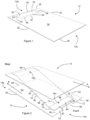
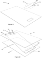
- the arrangement includes a first member 12 and a second member 14 that are coupled to one another via a drive member 16 or component in the form of a band.
- the arrangement When incorporated into a package the arrangement may be housed in a sleeve 18, with the band 16 arranged to encircle a divider 20 that defines a first chamber 22 and a second chamber 24 within the sleeve 18 of the package, and the first and second members 12, 14 housed in the first and second chambers 22, 24 respectively, when the package is in a closed position.
- the package is configured such that movement of the first member 12 in a first direction out of the sleeve 18 drives movement of the second member 14 in a second, opposing, direction out of the sleeve 18.
- the first member 12 is a substantially flat panel having a front end 12a and a rear end 12b, and comprising a front edge 26, a rear edge 28, a left edge 30, a right edge 32, an upper surface (not shown) and a lower surface 34.
- the first member comprises an attachment region comprising a first tear region 38 a first bonding region and a primary region that forms the remainder of the first member.
- the attachment region defines a portion of the first member 12 that can be pulled away from the remainder of the first member 12, i.e. the primary region, with ease on application of a force by a user.
- the attachment region is configured to detachably couple the primary region of the first member to the band.
- This attachment region 38 is beneficial, as it allows the different components of the arrangement to be separated from one another more easily than would otherwise be possible, for easy recycling of the arrangement.
- the attachment region allows for the cardboard primary regions of the first and second members to be completely separated from the plastic band.
- the first tear region 38 is rectangular in shape in this example, although the first tear region 38 may be other shapes in other embodiments.
- the first tear region 38 includes a rear edge 40, a front edge 42, a left edge 44 and a right edge 46.
- the rear edge 40 of the first tear region 38 is defined by a central portion of the rear edge 28 of the first member 12, and a first perforation 48 defines the front, left and right edges 42, 44, 46 of the first tear region 38. In this way, the attachment region of the first member is frangibly coupled to the primary region of the first member.
- the first bonding region 50 is provided in the first tear region 38 of the first member 12.
- the first bonding region 50 comprises a first adhesive strip 52 that attaches the first member 12 to the band 16 when the arrangement is assembled, as is illustrated in Figure 2 .
- the first adhesive strip 52 is rectangular in this embodiment, and is provided generally centrally in the first tear region 38.
- the first adhesive strip 52 is dimensioned so as to be contained entirely within the first tear region 38 when attached to the first member 12, with a first peripheral gap 54 provided between edges of the first adhesive strip 52 and the first tear region 38.
- the adhesive is ideally fully contained within the first tear region such that no adhesive is on the primary region of the first member when the arrangement is disassembled to enable quick and easy recycling of the first member.
- the second member 14 is also a substantially flat panel having a front end 14a and a rear end 14b, and comprising a front edge 56, a rear edge 58, a left edge 60, a right edge 62, an upper surface 64 and a lower surface (not shown).
- the front edge 56 of the second member 14 comprises a rectangular cut-out region 68 provided centrally along the width of the second member defined between its left and right edges 60, 62.
- the second member 14 comprises an attachment region comprising a second tear region 70 and a second bonding region, and a primary region that forms the remainder of the second member.
- the attachment region of the second member defines a portion of the second member 14 that can be pulled away from the primary region of the second member 14 with ease on application of a force by a user.
- the attachment region of the second member is thus configured to detachably couple the primary region of the second member to the band.
- the second tear region 70 includes a front edge 72, a rear edge 74, a left edge 76 and a right edge 78.
- the front edge 72 of the second tear region 70 is defined by a central portion of the front edge 56 of the second member 14, and encompasses the portion of the front edge 56 that defines the rectangular cut-out 68.
- a second perforation 80 defines the rear, left and right edges 74, 76, 78 of the second tear region 70.
- a second bonding, or attachment, region 82 is provided in the second tear region 70 of the second member 14.
- the second bonding region 82 comprises a second adhesive strip 84 that attaches the second member 14 to the band 16 when the arrangement is assembled, as illustrated in Figure 2 .
- the second adhesive strip 84 is rectangular in this embodiment, and is dimensioned so as to be contained entirely within the second tear region 70 when attached to the second member 14, with a second peripheral gap 86 between edges of the second adhesive strip 84 and the second tear region 70.
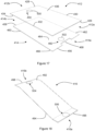
- the band, or belt member 16 comprises a strip of sheet material joined at its ends to form a continuous loop.
- the band 16 includes an interior surface 88 that defines an inner volume in which the divider 20 is received in use, and an exterior surface 90 that faces away from the inner volume.
- the band 16 when incorporated in the arrangement of this embodiment, is arranged such that it generally defines a rectangle in plan view (see Figure 11 ), and comprises upper and lower halves 92, 94 joined by front and rear edges 96, 98 provided at front and rear ends 16a, 16b of the band 16.
- the sheet material is typically a low-friction material, such as plastics film, that is selected so that the band 16 slides easily about the divider 20 when the arrangement is incorporated into a package for use.
- the first or front end 16a of the band 16 is bonded to the first member 12 at the first bonding region 50, and the second or rear end 16b of the band 16 is bonded to the second member 14 at the second bonding region 82. In this way, the first member 12 and the second member 14 are coupled to one another via the band 16.
- the band 16 is arranged to encircle the divider 20 of the package, which divides a tubular passage formed by the sleeve into a first, or upper, passage 100 which contains the first member 12 and a second, or lower, passage 102 which contains the second member 14.
- the first member 12 causes the band 16 to turn about the divider 20, since the first member 12 is secured to the band 16 at the first bonding region 50.
- Movement of the band 16 about the divider 20 causes the second member 14 to move in a second direction, opposed to the first direction, since the second member 14 is attached to the band 16 at the second bonding region 82.
- the bonding regions 50, 82 reach the ends of the divider 20, the first member 12 can be pulled no further in the first direction, and the package is in the fully open position, with the first and second members 12, 14 both extending out of the sleeve 18.
- the first member 12 When the user pushes the first member 12 in the second direction, the first member causes the band 16 to turn about the divider 20 such that the second member 14 moves in the first direction, back into the sleeve 18.
- the first and second bonding regions 50, 82 reach the opposite ends of the divider 20, the first member 12 can be pushed no further into the package, and the package is in the fully closed position, with the first and second members 12, 14 both housed within the sleeve 18 in the first and second chambers 22, 24, respectively.
- Separating the band 16 from the first and second members 12, 14, i.e. separating the components of the arrangement, may be achieved as follows. With the arrangement in the configuration shown in Figure 2 , the user grips the first member 12 at its front end 12a with one hand and grips the second member 14 at its rear end 14b with the other hand. The user then pulls the first member 12 in a first pull direction indicated by arrow A, and the second member 14 in a second pull direction indicated by arrow B, such that the first and second members 12, 14 are pulled away from one another, in opposite directions. When the band 16 extends between the first and second members 12, 14 and is taut, the user simply continues to pull until the first and second tear regions 38, 70 separate from the surrounding regions of the first and second members 12, 14, respectively.
- the package is configured such that a greater force is required to separate the first and second members 12, 14 from the band 16, than is required to remove the first and second tear regions 38, 70, respectively, from the surrounding region of the first and second members 12, 14.
- a greater force is required to separate the first and second members 12, 14 from the band 16, than is required to remove the first and second tear regions 38, 70, respectively, from the surrounding region of the first and second members 12, 14.
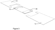
- Figure 3 illustrates the arrangement in a disassembled state, after the components of the arrangement have been pulled apart for disposal.
- the tear regions 38, 70 of the first and second members 12, 14 remain attached to the band.
- the first and second members 12, 14 are now ready to be recycled with other suitable cardboard components of the package, being free from the plastic material of the band 16 or any adhesive, which all remains attached to the band 16.
- the attachment regions of the first and second members are configured to be detachable from the primary regions of the first and second members. As will be illustrated in the following, it is possible for the attachment region to be detachable from the band.
- FIGs 4 to 16 illustrate another arrangement and package.
- This arrangement is configured so as to be easily separable for disposal. Furthermore, this arrangement is advantageous because its features provide for easy assembly of the arrangement, thus saving time, effort and cost in the assembly process, as will be explained.
- Figure 4 shows the arrangement of this example incorporated into a sleeve 218 to provide a package.
- the arrangement of Figure 4 comprises a first member 212, a second member 214 and a band 216, and is housed in a sleeve 218 when assembled in the package.
- the sleeve 218 comprises a flat blank 300, which has a first or inner surface 302 on one side and a second or outer surface (not visible in Figure 5 ) on the other side.
- the sleeve 218 is manufactured by cutting and creasing or scoring a sheet of flexible cardboard, plastics, tear-resistant laminate, or other material.
- the sleeve 218 is made from a 0.5 mm thick mineral-filled polypropylene sheet, such as that sold under the registered trade mark PRO-Print. In this way, the sheet is flexible enough to allow for the bending that is necessary to form the sleeve 218, but is stiff enough to provide structural support.
- the blank 300 comprises a front end 300a and a rear end 300b and consists of seven integral, substantially oblong sections or panels 304, 306, 308, 310, 312, 314, 316, each extending from the front end 300a to the rear end 300b of the blank 300.
- Four of the sections namely a divider 304, a lower inner wall 308, an upper wall 312 and a lower outer wall 316 are relatively wide, and three, namely a left inner wall 306, a right outer wall 310, and a left outer wall 314, are relatively narrow.
- the lower inner wall 308, the upper wall 312 and the lower outer wall 316 are of substantially the same length: that length is greater than the width of the sections in the drawings, but it need not be greater.
- the divider 304 is shorter in length than the lower inner wall 308, the upper wall 312 and the lower outer wall 316.
- the sections 304, 306, 308, 310, 312, 314, 316 of the blank 300 are integral and demarcated from each other by folds or scores 318.
- the folds 318 are all made such that the first surface 302 of the flat blank 300 lies inward and the sleeve 218 is formed into a fully-folded configuration, shown in Figure 6 , by folding the flat blank 302 along the folds 332 successively in a coil-like manner, starting with the divider.
- the upper wall 312 of the sleeve 218 comprises a curved indentation 320 or cut-out at the front end 300a of the blank 300.
- the lower inner and outer walls 308, 316 each comprise a rectangular indentation or cut-out 322 at the front end of the blank.
- the curved indentation 320 of the upper wall 312 and the rectangular indentations 322 of the lower inner and outer sections 308, 316 of the sleeve 218 are aligned with each other.
- the curved indentation 320 may align with a curved indentation of a blister-pack housed within the package.
- Figures 7 and 8 show the first member 212 of the arrangement of Figure 4 .
- the first member 212 comprises a blank 324 that includes first and second panels 326, 328, each of which are substantially planar.
- the first panel 326 has a front end 330, a rear end 332, a left side 334, a right side 336, a first or inner surface (not shown in Figure 7 ) and a second or outer surface 338.
- the second panel 328 has a front end 342, a rear end 344, a left side 346, a right side 348, a first or inner surface (not shown in Figure 7 ) and a second or outer surface 350.
- the first and second panels 326, 328 each comprise an attachment region or portion 354a, 354b, which together define a first attachment region or portion 354 of the first member 212 when the first member 212 is formed, at which the band 216 is attached to the first member 212 when the arrangement is assembled, as will be explained.
- the attachment region 354a of the first panel 326 is located towards the rear end 332 of the first panel 326, and centrally across the width of the first panel 326 defined between the left and right side edges 334, 336 of the first panel 326.
- the attachment region 354a of the first panel comprises an attachment feature in the form of an anchoring feature 356.
- the anchoring feature comprises first and second flaps 356a, 356b, that are generally rectangular in shape in this embodiment, and are defined by cuts in the first panel 326.
- the first and second flaps 356a, 356b together extend over approximately half of the width of the first panel 326.
- the first flap 356a comprises front and rear edges 358, 360 joined by left and right side edges 362, 364.
- the left side edge 362 adjoins to a surrounding region of the first panel at a first fold or score 366, also referred to as a hinged portion of the first panel.
- the front, rear and right side edges 358, 360, 364 are defined by first front, first rear, and side cuts in the first panel 326, such that these edges are not connected to the surrounding region of the first panel 326.
- the second flap 356b comprises front and rear edges 368, 370 joined by left and right side edges 372, 374.
- the right side edge 374 adjoins to a surrounding region of the first panel 326 at a second fold or score 376, also referred to as a hinged portion of the second panel.
- the front, rear and left side edges 368, 370, 372 are defined by second front, second rear and the side cut in the first panel 326, such that these edges are not connected to the surrounding region of the first panel 326.
- the right side edge 364 of the first flap 356a and the left side edge 372 of the second flap 356b lie adjacent and are parallel to one another.
- the distance between front and rear edges of the first and second flaps 356a, 356b defines a width of the attachment region 354a of the first panel 326.
- the distance between the left side edge 362 of the first flap 356a and the right side edge 374 of the second flap 356b defines a length of the attachment region 354a of the first panel 326.
- the length of the attachment region 354a is approximately half the width of the first panel 326.
- the first and second flaps 356a, 356b are configured to be foldable between an unfolded position in which the flaps 354a, 354b are flush with the surrounding portion of the first panel 326, and a folded position in which the flaps 356a, 356b are bent or folded along the folds 366, 376, so as to extend generally perpendicularly to the plane of the first panel 326.
- a band-receiving aperture 356 is created in the first panel 326, in the area that houses the flaps 356a, 356b in their unfolded position.
- the hinged portions adjoining the flaps to the primary region of the member reveal an opening in the first panel.
- the attachment region 354b of the second panel 328 is located towards the rear end 344 of the second panel 328, and centrally across the width of the second panel 328 defined between the left and right side edges 346, 348 of the second panel 328.
- the attachment region 354b of the second panel 328 comprises an attachment feature that comprises an opening.
- the opening is in the form of an elongated band-receiving slot 378 defined by front and rear edges 380, 382 and left and right side edges 384, 386.
- the distance between front and rear edges 380, 382 of the slot 378 defines a width of the attachment region 354b of the second panel 328.
- the distance between the left and right side edges 384, 386 of the slot 378 defines a length of the attachment region 354b of the second panel 328.
- the length of the attachment region 354b is approximately half the width of the second panel 328.
- the first and second panels 326, 328 adjoin at a blank fold or score 388 provided between their front ends 330, 342.
- the blank 324 is folded at the blank fold 388, and the inner surfaces 338, 350 of the first and second panels 326, 328 are bonded to each other by means of adhesive provided on one or both of the inner surfaces 338, 350.
- the first and second panels are arranged one on top of the other, in a face-to-face arrangement.
- the first and second panels are coplanar to define a double wall, with the first panel defining a first wall and the second panel defining a second wall.
- the front and rear ends and the left and right sides of the first and second panels 326, 328 align to form front and rear ends 212a, 212b and left and right sides 230, 232 of the first member 212, respectively, as shown in Figure 8 .
- the distance between the front and rear ends 212a, 212b of the first member 212 defines a length of the first member 212 and the distance between the left and right sides 230, 232 of the first member 212 defines a width of the first member 212.
- the attachment regions 354a, 354b of the first and second panels 326, 328 align to form the first attachment region 354 of the first member 212.
- the attachment regions 354a, 354b of the first and second panels 326, 328 extend across substantially the same width of the first member 212, this being approximately half the width of the first member 212, and are provided centrally, in the same position across the width of the first member 212.
- the slot 378 of the attachment region 354b of the second panel 328 is positioned centrally across the width of the first and second flaps 356a, 356b, and extends across approximately 1/6 of the width of the first and second flaps 356a, 356b in this embodiment.
- the slot of the second panel is adjacent the flaps of the first panel when the first member is formed.
- the second member 214 of the arrangement of Figure 4 is identical to the first member 212, apart from that the second member 214 includes a rectangular cut-out 390 at the rear edges 392, 394 of the first and second panels 396, 398, that together define a rectangular cut-out 390 of the second member 214 when the second member 214 is formed.
- the rectangular cut-out 390 of the second member 214 aligns with the rectangular and curved indentations or cut-outs 320, 322 of the sleeve 218 when the package is in the closed position.
- the band 216 is identical to the band 16 of the embodiment of Figures 1 to 3 , and will not be described again in detail here for conciseness.
- the band 216 is attached to the first and second members 212, 214 at their respective attachment regions 354.
- the first and second flaps 356a, 356b of the first member are folded outwards, along their joining edges 366, 376, into the unfolded position illustrated in Figure 13 .
- the rear end of the band 216b is slotted through the band-receiving slot 378 and the band-receiving aperture 356 in succession, and is pulled in a first band direction, X, so that a first minor portion of the band 216 extends from the band-receiving aperture 356.
- the first band direction X is substantially perpendicular to the plane of the first member 212, but it should be understood that this is not required.
- the upper and lower halves 292, 294 of the band 216 that define the first minor portion are arranged to create a first minor volume, defined between interior surfaces of the first minor portion of the band 216, in which the flaps 356a, 356b can be received.
- the flaps 356a, 356b are then folded inwards along their joining edges 366, 376, into the unfolded or flush position, such that inner surfaces of the flaps 356a, 356b engage with the interior surface of the band 216.
- the front end 216a of the band 216 is pulled in a second band direction Y, generally opposite to the first band direction X, until the interior surface of the band 216 engages with the outer surfaces of the flaps 356a, 356b.
- the band is now attached to the first member 212, and the flaps 356a, 356b are essentially surrounded by the band 216 to form a mechanical connection between the band 216 and the first member 212.
- the method for attaching the band 216 to the second member 214 is essentially the same as the method for the first member 212.
- the first and second flaps 356a, 356b of the second member 214 are folded outwards, along their joining edges 366, 376, into the unfolded position.
- the front end 216a of the band 216 is slotted through the band-receiving slot 378 and the band-receiving aperture 356 in succession, and is pulled in the second band direction, Y, so that a second minor portion of the band 216 extends from the band-receiving aperture 356.
- the upper and lower halves 292, 294 of the band 216 that define the minor portion are arranged to create a second minor volume, defined between interior surfaces of the first minor portion of the band 216, in which the flaps 356a, 356b can be received.
- the flaps 356a, 356b are then folded inwards along their joining edges 366, 376, into the unfolded or flush position, such that inner surfaces of the flaps 356a, 356b engage with the interior surface of the band 216.
- the band 216 is pulled in the first band direction X until the interior surface of the band 216 engages with the outer surfaces of the flaps 356a, 356b.
- the band 216 is now attached to the second member 214, and the flaps 356a, 356b are essentially surrounded by the band 216 to form a mechanical connection between the band and the second member 214.
- Figure 4 shows the arrangement of this example incorporated into a sleeve 218 to provide a package.
- Figures 14 to 16 illustrate further views of the arrangement incorporated in the sleeve 218 of Figure 5 to form a package.
- Figures 14 and 15 show the arrangement fully housed within the sleeve 218 in a fully retracted position that corresponds to a fully closed position of the package.
- Figures 14 and 15 illustrate the positions of the first and second attachment regions 354 when the package is in the closed position.
- Figure 16 shows a perspective view of the package when the arrangement is in a fully extended position that corresponds to a fully open position of the package.
- FIG. 4 The arrangement of Figure 4 is disassembled in essentially the same manner as described previously, in that the first and second members, in particular primary regions of the first and second members, are gripped by a user and pulled away from one another to disengage the mechanical engagement between the band and the flaps of the first and second members.
- the attachment regions are configured to be detachable from the band, rather than from the primary regions of the first and second members.
- this example advantageously provides complete separation of the plastics material of the band and the cardboard material of the first and second members.
- the arrangement of this example includes substantially planar, generally rectangular, first and second members 412, 414 that are coupled to each other by a band 416.
- the first member 412 has a front end 412a and a rear end 412b, and comprising a front edge 426, a rear edge 428, a left edge 430, a right edge 432, an upper surface 436 and a lower surface 434.
- the second member 414 has a front end 414a and a rear end 414b, and comprising a front edge 456, a rear edge 458, a left edge 462, a right edge 460, an upper surface 464 and a lower surface 466.
- the second member 414 further comprises a rectangular cut-out region 468 provided at its front edge 456, and located centrally along a width of the second member 414 defined between its left and right edges 462, 460.
- the first member 412 comprises a first aperture or opening defined in a primary region of the first member.
- the first aperture is provided towards a rear end 412b of the first member 412, a small distance back from a rear edge 428 of the first member 414.
- the first opening 500 is generally circular and defines a through-hole in the first member 412. That is, the first opening 500 extends through the full thickness of the first member 412 defined between upper and lower surfaces 436, 434 of the first member 412.
- the first opening 500 is formed as a die-cut hole.
- the first opening 500 may be formed by another method, and the first opening 500 may extend only partially through the thickness of the first member 412.
- the attachment region 482 of the second member 414 comprises a second aperture or opening defined in a primary region of the second member.
- the second aperture is provided towards a front end 414a of the second member, a small distance back from a front edge 456 of the second member 414, and comprises a second aperture or opening 502 that is essentially identical to the first opening 500 of the first member 412, although this is not a requirement. That is, the attachment region 482 of the second member 414 comprises a generally circular opening 502 in the form of a through-hole, formed by die-cutting. In other examples it would be possible for the second opening 502 to differ from the first opening 500 in shape, form, and/or method of manufacture.
- the first and second members 412, 414 each include attachment regions 450, 482 at which the first and second members 412, 414 are attached to the band 416 when the arrangement is assembled.
- the first and second attachment regions are provided in the form of first and second adhesive studs.
- the first and second adhesive studs are identical, and each comprise a generally cylindrical body having first and second, substantially flat, faces joined by a curved outer surface.
- the body of each of the adhesive studs is dimensioned so as to be received in the first and second openings in a close-fit.
- the band 416 is arranged such that it generally defines a rectangle in plan view and comprises upper and lower halves 492, 494 joined by front and rear edges 496, 498 provided at front and rear ends 416a, 416b of the band 416.
- the first and second adhesive studs 504, 506 are attached to the band 416 by means of an adhesive.
- the first adhesive stud 504 is bonded or attached to the exterior surface of the upper half 492 of the band 416 via the first face 504a of the stud, at a position towards the rear end 416b of the band 416 and centrally across a width of the band 416 defined between left and right side edges of the band 416.
- the second adhesive stud 506 is bonded or attached to the exterior surface of the lower half 494 of the band 416 via the first face 506a of the stud 506, at a position towards the front end 416a of the band 416 and centrally across the width of the band 416.
- the first opening 500 of the first member 412 is aligned with the first adhesive stud 504, such that the front and rear ends 416a, 416b, 412a, 412b of the band 416 and the first member 412 are generally aligned, and the lower surface 434 of the first member 412 and the exterior surface of the upper half 492 of the band are facing one another.
- the first adhesive stud 504 is then inserted into the first opening 500, in which it is received in a close-fit. In other words, the first adhesive stud 504 is push-fit into the first opening 500.
- the attachment region of the first member in the form of the first adhesive stud detachably couples the primary region of the first member to the band.
- a similar procedure is followed to attach the second member 414 to the band 416.
- the second opening 502 of the second member 414 is aligned with the second adhesive stud 506, such that the front and rear ends 416a, 416b, 414a, 414b of the band 416 and the second member 414 are aligned, and the upper surface 464 of the second member 414 and the exterior surface of the lower half 494 of the band 416 are facing one another.
- the second adhesive stud 506 is then inserted, or push-fit, into the second opening 502, such that the second member 414 and the band 416 are coupled to one another. That is, the attachment region of the second member in the form of the second adhesive stud detachably couples the primary region of the second member to the band.
- the shape, dimensions and method of making the openings 500, 502 of the first and second members 412, 414 may differ from the example of Figures 17 to 19 , and/or may differ from each other.
- the openings 500, 502 of the first and second members 412, 414 are through-holes in this example, the first and second openings 500, 502 may extend only partially through the thickness of the or each member 412, 414 in other examples.
- the shape and dimensions of the adhesive studs 504, 506 may differ from that described.
- the studs 504, 506 may each comprise a circumferential flange extending about their first faces 504a, 506a.
- the studs 504, 506 may attach the band 416 to the members 412, 414 in a purely mechanical manner, without the need for an adhesive such as glue.
- the band 416 may comprise apertures through which the adhesive studs 504, 506 are received before being inserted in a push-fit into the openings 500, 502 of the first and second members 412, 414, such that the circumferential flanges of the studs 504, 506 form limiting and holding means.
- the flanges may act to prevent the studs 504, 506 from being pushed too far through the openings of the members 412, 414, especially in the case where the openings 500, 502 of the members 412, 414 are through-holes. Furthermore, when the arrangement is assembled, the circumferential flanges engage with the interior surface of the band 416, such that the band 416 is sandwiched and held between the circumferential flange of the adhesive studs 504, 506 and the lower and upper surfaces 434, 464 of the first and second members 412, 414.
- a user grips the primary regions of the first and second member, and tugs or pulls the first and second members away from one another.
- the first and second adhesive studs are pulled out of the first and second apertures of the first and second members.
- the first and second adhesive studs of the first member remain attached to the band, and the primary regions of the first and second members are separated from the attachment regions, i.e. the adhesive studs, of the first and second members.
- the attachment regions i.e. the first and second adhesive studs, are configured to be detachable from the primary regions of the first and second members.
- Figures 20 to 24 illustrate another arrangement.
- the arrangement comprises a first member 712, a second member 714 and a band 716, and may be housed in a sleeve such as that of Figures 5 and 6 when assembled in a package.
- the first member has a front end, a rear end, a left side, a right side, a first or inner surface and a second or outer surface.
- the second member has a front end, a rear end, a left side, a right side, a first or inner surface and a second or outer surface.
- the first member comprises a primary region 718 and a rectangular aperture 720 or through-hole defined in the primary region.
- the rectangular aperture 720 is located towards the rear end of the first member, and centrally across the width of the first member defined between the left and right side edges of the first member.
- the second member comprises a primary region and a rectangular aperture or through-hole located towards the front end of the second member, and centrally across the width of the second member defined between the left and right side edges of the second member.
- the first and second members further each comprise an attachment region that detachably couples the primary region of the first and second members to the band.
- the attachment regions comprise first and second coupling means 722, 724, respectively, for detachably coupling the band to the members.
- the first and second coupling means 722, 724 are identical to each other in this example. Thus, only the first coupling means will be described for conciseness.
- the first coupling means 722 comprises a first adhesive strip 726 and a first coupling member 728.
- the first adhesive strip is rectangular in shape, and is dimensioned so as to extend across substantially the full width of the band when attached to the band in the assembled state of the arrangement, as best appreciated with reference to Figure 22 .
- the first coupling member 728 is formed of a folded, generally flat, blank that comprises five rectangular sections or panels.
- the blank of the first coupling member includes three major panels and two minor panels.
- the three major panels define a central panel 731 of the blank and first and second outer panels 732, 734 respectively of the blank.
- the minor panels comprise a first minor panel 736 that is positioned between the first outer panel 732 and the central panel 731, and a second minor panel 738 that is positioned between the second outer panel 734 and the central panel 731.
- the panels of the blank are integral and demarcated from each other by folds or scores 740.
- a first fold adjoins the first outer panel 732 and the first minor panel 736
- a second fold adjoins the first minor panel 736 and the central panel 731
- a third fold adjoins the central panel 731 and the second minor panel 738
- a fourth fold adjoins the second minor panel 738 and the second outer panel 734.
- the minor portions are substantially perpendicular to the major portions, and the first coupling member 728 defines a top-hat profile, which is best illustrated in Figure 22 which shows the first coupling member 728 integrated into the arrangement.
- an outer surface of the central panel 731 defines a band-engagement surface and an inner surface of the central panel 731 defines an adhesive-strip engagement surface.
- the outer panels 732, 734 define member-engaging surfaces that engage with the first and second member 712, 714 in the assembled arrangement for mechanical coupling of the members to the band 716.
- the minor panels 736, 738 have a width that is substantially equal to, or slightly greater than, a thickness of the first member 712 defined between its upper and lower surfaces 750, 752.
- the central panel has a width that is substantially equal to, or slightly less than, a width of the aperture of the first member.
- the second coupling means 724 is identical to the first coupling means 722, comprising a second adhesive strip 826 and a second coupling member 828 identical to the first adhesive strip 726 and the first coupling member 728 of the first coupling means 722, and will therefore not be described here in detail.
- Like parts of the first and second coupling means are provided with like reference numerals.
- first and second coupling means 722, 724 are attached to the band 716, and the first and second members 712, 714 are then attached to the band 716 at, and by means of, the first and second coupling means 722, 724.
- the first coupling means 722 is attached to the exterior surface 754 of the upper half 756 of the band 716, at the rear end of the band, and the second coupling means is attached to the exterior surface of the lower half 760 of the band 716, at the front end of the band 716.
- the first coupling means 722 is attached to the band 716 as follows.
- the first coupling member 728 is positioned towards the rear end, and centrally across the width, of the band 716.
- the outer surface of the central panel 731 is engaged with the exterior surface 754 of the upper half 756 of the band 716.
- the adhesive strip 726 is positioned across the width of the band 716, such that a central region of the adhesive strip 726 contacts and adheres to the inner surface of the central panel 731.
- Outer regions of the adhesive strip 726 at either side of the central region contact and adhere to the exterior surface 754 of the upper half 756 of the band 716. In this way, the adhesive strip 726 bonds the first coupling member 728 to the band.
- the outer panels or flaps of the first coupling member 728 are spaced from the band 716 by a gap by virtue of the minor panels of the first coupling member.
- the size of the gap, corresponding to a width of the minor panels, is dimensioned to be substantially equal to a thickness of the first member 712 defined between its upper and lower surfaces.
- the method of attaching the second coupling means to the second member is substantially the same as the method for attaching the first coupling means to the first member.
- the second coupling member is positioned towards the front end, and centrally across the width, of the band.
- the outer surface of the central panel is engaged with the exterior surface of the lower half of the band.
- the adhesive strip is positioned across the width of the band, such that a central region of the adhesive strip contacts and adheres to the inner surface of the central panel, and outer regions of the adhesive strip at either side of the central region contact and adhere to the exterior surface of the lower half of the band. In this way, the adhesive strip bonds the second coupling member to the band.
- the outer panels of the second coupling member are spaced from the band by a gap by virtue of the minor panels of the second coupling member.
- the size of the gap, corresponding to a width of the minor panels, is dimensioned to be substantially equal to a thickness of the second member defined between its upper and lower surfaces.
- first and second coupling means are attached to the band, the first and second members are coupled or attached to the band via the first and second coupling means.
- the outer panels of the first coupling member are folded inwardly towards one another, and are inserted through the aperture in the first member. Specifically, the first and second outer panels are pivoted about the first and fourth folds until the first and second outer panels extend substantially perpendicularly with respect to the plane of the central panel. Because the width of the central panel of the first coupling member is substantially equal to the width of the aperture of the first member, this allows the first and second outer panels to be inserted through the first aperture simultaneously.
- the lower surface of the first member is brought into contact with the exterior surface of the band, and the first and second outer panels are folded outwards, away from one another, until the member-engaging surfaces of the outer panels engage the upper surface of the first member. In this way, the first member is coupled to the band via the first coupling means.
- the second member is coupled to the second coupling means of the band in essentially the same manner as the first member is coupled to the first coupling means, and will therefore not be described here in detail for conciseness.
- the arrangement of Figures 20 to 24 is advantageous, as it is easy to disassemble into its constituent parts, and thus provides a benefit in terms of ease of disposal for recycling.
- Separating the band from the first and second members i.e. disassembling the arrangement, may be achieved in essentially the same manner as for previous arrangements. That is, a user may grip the first and second members at their front and rear ends respectively, and pull or tug the first and second members in opposite directions to release the mechanical engagement between the first coupling member and the first member and the second coupling member and the second member. In this way, the first and second outer panels are pulled out of the apertures of the first and second members.
- the first and second attachment regions of the first and second members remain attached to the band, and the primary regions of the first and second members are separated for easy recyclability.
- the first and second coupling means When disassembled in this way, the first and second coupling means remain attached to the band, but the first and second members are completely separated from the band and other parts of the arrangement for recycling.
- the primary regions of the first and second members are formed of a non-plastics material, in these examples of cardboard, and the band is formed of a plastics material.
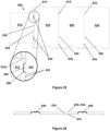
- Figures 25 to 28 illustrate an alternative sleeve for use in a package.
- the sleeve comprises a flat blank 802, which is substantially the same as the flat blank of Figure 4 , manufactured in the same way by cutting and creasing or scoring a sheet of flexible cardboard, plastics, tear-resistant laminate, or other material.
- the sheet is flexible enough to allow for the bending that is necessary to form the sleeve 800, but is stiff enough to provide structural support.
- the blank 802 of Figure 25 consists of seven integral, substantially oblong sections or panels 812, 814, 816, 818, 820, 822, 824.
- Four of the sections namely a divider panel 812, a lower panel 816, an upper panel 820 and a secondary lower panel 824 are relatively wide, and three, namely a first side wall 814, a second side wall 818, and a third side wall 822, are relatively narrow.
- the divider panel 812 divides the space between the upper and lower panels 816, 820, to define upper and lower compartments in the sleeve.
- the sections 812, 814, 816, 818, 820, 822, 824, each of the blank 802 are integral and demarcated from each other by folds or scores 832 (see inset of Figure 25 ).
- the first side wall 814 joins a first edge 834 of the divider panel 812 to a first edge 836 of the lower panel 816, and meets those edges at boundaries defined by folds.
- the second side wall 818 joins a second edge 838 of the lower panel 816 to a second edge 842 of the upper panel 820 and meets those edges at boundaries defined by folds.
- the third side wall 822 joins a first edge 844 of the upper panel 820 to a second edge 846 of the secondary lower panel 824 and meets those edges at boundaries defined by folds.
- the sleeve blank 802 of Figure 25 differs from the sleeve blank of Figure 4 primarily in that the sleeve blank 802 of Figure 25 additionally comprises protrusions 840 that protrude from the first side wall 814 of the blank 802.
- the first side wall 814 defines a side wall plane and the protrusions 840 protrude away from the first sidewall 814 substantially in the first side wall plane.
- the protrusions 814 protrude from the first side wall 812 beyond the first edge 834 of the divider panel 812 to support the upper panel 820 along its first edge 844.
- the protrusions 840 act to hold the upper panel 820 away from the divider panel 812 at its first edge 834, thereby preventing compression of the upper compartment of the sleeve.
- the first side wall 812 has a first height h 1
- the second side wall 818 has a second height h 2 that is greater than the first height h 1
- the upper panel 820 is held parallel to the lower panel.
- the protrusion 840 is formed by being 'reclaimed' from the divider panel 812.
- the fold or boundary 832a between the divider panel 812 and the first side wall 816 is interrupted by the protrusion 840.
- the divider panel 812 comprises a cut-out 850, and the protrusion 840 protrudes beyond the foldable boundary 832a into the cut-out 850.
- the portion that is cut out of the divider 812 by the cut-out 850 forms the protrusion, so that the shape of the cut out defines the shape of the protrusion.
- the cut-out 850 in the divider panel 812 accommodates the protrusion 840.
- the protrusion 840 remains in the plane of the first side wall 814, rather than the plane of the divider panel 812, such that the protrusion 840 stands proud of the first side wall 814 and extends upwardly to protrude above the divider 812. This also reveals the cut-out 850 in the divider panel 812.
- the protrusion 840 comprises a first edge 852 joined to the first side wall 814 and a second edge 854 opposite the first edge 852.
- the second edge 854 is a free edge that, in the folded sleeve, supports the upper panel.
- the first and second edges 852, 854 of the protrusion 840 are joined by respective third and fourth edges 856, 858.
- a length of the first edge 852 is greater than a length of the second edge 854.
- the third and fourth edges 856, 858 are sloped between the first and second edges 852, 854, and in particular define an acute angle to the first edge 852 and an obtuse angle to the second edge 854.
- the protrusion 840 has a trapezoidal shape.
- the sloping of the third and fourth edges 856, 858, and the obtuse angle with the free edge 854 of the protrusion 840 facilitates separation of the protrusion 840 from the divider panel 812 when the blank is folded for assembly, and also makes the free corners of the protrusion (i.e. the corners between the second edge 854 and the third and fourth edges 856, 858) more resistant to wear.
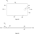
- Figures 29 to 33 illustrate another arrangement.
- the arrangement comprises substantially planar, generally rectangular, first and second members 912, 914, which are also referred to as moveable members.
- the first and second members 912, 914 are each couplable to a band 916, and in this way are couplable to each other by the band 916.
- the first member 912 has a front end 912a and a rear end 912b, and comprises a front edge 926, a rear edge 928, a left edge 930, a right edge 932, an upper surface 936 and a lower surface 934.
- the upper surface 936 as shown defines a running surface that lies parallel to the divider and faces the band.
- the first member 912 further comprises a first recess 900 that defines a first recess region or attachment region 939 of the first member 912. The remainder of the first member 912 not defined by the first attachment region 939 defines a primary region of the first member 912.
- the first attachment region 939 defines a portion of the first member 912 at which the band 916 is attached when the arrangement is assembled. As in the other described arrangements, the first attachment region 939 is configured to detachably couple the primary region of the first member 912 to the band 916.
- the first recess 900 is provided towards the rear end 912b of the first member 912, a small distance back from the rear edge 928 of the first member 912, and centrally across the width of the first member 912 defined between its left and right edges 930, 932.
- the first recess 900 extends partially through the thickness of the first member 912 defined between the upper and lower surfaces 936, 934.
- the first recess 900 is generally circular, and is formed as a debossed hole or depression in the upper surface 936 of the first member 912. As illustrated in Figure 30 , the first recess 900 has a slight taper, and terminates at a base 940 of the first recess 900. A vertical spacing between the base 940 of the recess and the running surface 936 defines a depth of the recess.
- the first recess 900 extends approximately halfway through the thickness defined between the upper and lower surfaces 936, 934 of the first member 912 in this embodiment.
- the first recess 900 may extend through a greater or lesser extent of the thickness of the first member 912, and may take a different shape, so long as the first recess 900 is suitable for accommodating an adhesive material (not shown).
- the adhesive material lies flush or sub-flush with the running surface 936 of the first member 912 when accommodated in the first recess 900, and couples the first member 912 to the band 916 when the arrangement is assembled.
- the adhesive material may be glue, for example, or may take the form of any other suitable adhesive substance.
- the second member 914 is of a different construction to the first member, but may perform essentially the same function.
- the second member comprises first and second panels or walls 926, 928, joined by a hinge 988.
- Figure 31 shows that second member 914 is formed by a blank 924. In its unfolded state, the first and second panels 926, 928 lie end-to-end, joined by the hinge 988.
- the first panel 926 has a front end 930, a rear end 932, a left side 934, a right side 936, a first or inner surface (not shown in Figure 31 ) and a second or outer surface 938.
- the second panel 928 has a front end 942, a rear end 944, a left side 946, a right side 948, a first or inner surface (not shown in Figure 31 ) and a second or outer surface 950.
- the first and second panels each include a rectangular cut-out 990 at their rear edges, which together define a rectangular cut-out of the second member 914 when the second member 914 is formed, that is positioned at the rear edge 958 of the second member 914, and located centrally along a width of the second member 914 defined between its left and right edges 962, 960.
- the first panel 926 further comprises a panel aperture or opening 970 that is located towards the rear end 932 of the first panel 926, and centrally across the width defined between the left and right side edges 934, 936 of the first panel 926.
- the panel opening 970 is formed as a die-cut hole, but in other embodiments the panel opening 970 may be formed by another method. Also, it would be possible for the panel opening 970 to extend only partially through the thickness of the first panel 926.
- the hinge 988 is defined by a fold or score provided between the front ends 930, 942 of the panels.
- the blank 924 is folded at the blank fold 988, and the inner surfaces of the first and second panels 926, 928 are bonded to each other by means of adhesive provided on one or both of the inner surfaces.
- the first and second panels 926, 928 are arranged one on top of the other, in a face-to-face arrangement.
- the first and second panels 926, 928 are coplanar to define a double wall, with the first panel 926 defining a first wall and the second panel 928 defining a second wall.
- the front and rear ends and the left and right sides of the first and second panels 926, 928 align to form front and rear ends 914a, 914b and the left and right sides 930, 932 of the second member 914.
- the fully-formed second member also defines a left edge 962, a right edge 960, an upper surface 964 and a lower surface 966.
- the lower surface 966 defines a running surface that lies parallel to the divider and faces the band.
- the first and second panels 926, 928 together create a second recess 980 that defines a second recess region or attachment region 954.
- the second attachment region 954 is provided at the rear edge 958 of the second member, and is located centrally along a width of the second member 914 defined between its left and right edges 962, 960.
- the band 916 is attached to the second member 914 at this second attachment region 954 when the arrangement is assembled, which is configured to detachably couple the primary region of the second member 914 to the band 916.
- the remainder of the second member 914, surrounding the second attachment region defines a primary region of the second member 914.
- the second recess 980 is defined by the opening 970 in the first panel 926 and a continuous portion of the second panel 928 that overlies the opening 970 when the second member 914 is formed. In this way, the continuous portion of the second panel 928 forms a base 972 of the second recess 980.
- the second recess 980 of the second member 914 accommodates an adhesive material (not shown) for coupling the second member 914 to the band 916.
- the adhesive material lies flush or sub-flush with the lower surface 966 of the second member 914 when accommodated in the second recess 980.
- a spacing between the lower surface or running surface 966 and the base 972 defines a depth of the recess 980.
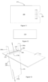
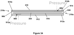
- FIG. 29 A method of assembling a package incorporating the arrangement of Figures 29 to 32 will now be described with reference to Figures 33 and 34 .
- the arrangement of Figures 29 to 32 is incorporated into a sleeve such as that illustrated in Figures 5 and 6 .
- a sleeve blank 300 such as that shown in Figure 5 is provided, and the band 916 is arranged to encircle the divider 304 of the sleeve blank 300.
- the strip of sheet material that forms the band 916 is arranged to encircle the divider 304 of the sleeve blank 300, and the ends of the sheet material are joined to form the band 916 around the divider 304.
- the divider 304 also referred to as a substrate, may not be integral with a sleeve or other component of the package in all examples.
- the divider 304 may simply be a planar sheet of material that can be fixed in a sleeve, for example using an adhesive or some mechanical means, in order to form the package.
- the sleeve blank 300 is folded along the folds 332 successively in a coil-like manner, starting with the divider 304, to form a sleeve 218 that includes an upper passage 100 and a lower passage 102.
- the first and second members 912, 914 are prepared and incorporated into the package as follows.
- an adhesive material is arranged in the first recess 900 of the first member 912 and the second recess 982 of the second member 914.
- the adhesive material is arranged so as to lie flush or sub-flush with the upper surface 936 of the first member 912 and the lower surface 966 of the second member 914, each of which define a running surface of their respective member 912, 914. In use, when the arrangement or package is assembled, the running surface will face the band 916.
- a depth of the adhesive material in a direction substantially orthogonal to the running surface does not exceed a depth of the respective recess.
- Arranging the adhesive material in this way is advantageous, as it guards against the adhesive material transferring to the band 916 or other components of the package before it is intended. In the finished article, it also ensures that the first and second members 912, 914 can lie flat against the divider or substrate 304, without being spaced away from the substrate 304 in the region of the adhesive.
- the first and second members 912, 914 are inserted into the sleeve 218.
- the first member 912 is inserted into the lower passage 102 of the sleeve 218, with the upper surface 936, i.e. the running surface, of the first member 912 facing towards the band 916.
- the first member 912 is inserted into the sleeve 218 so that the front end 912a of the first member 912 enters the sleeve 218 before the rear end 912b of the first member 912.
- the first member 912 is then pushed into the sleeve 218 until the ends 912a, 912b of the first member 912 generally align with ends 218a of the sleeve 218, as is shown in Figure 34 .
- the second member 914 is inserted into the upper passage 100 of the sleeve 218, with the lower surface 966, i.e. the running surface, of the second member 914 facing towards the band 916.
- the second member 914 is inserted into the sleeve 218 at the opposing end of the sleeve to that at which the first member 912 is inserted.
- the second member 914 is inserted into the sleeve 218 such that the front end 914a of the second member 914 enters the sleeve 218 before the rear end 914b of the second member 914, and is then pushed into the sleeve 218 until the ends 914a, 914b of the second member 914 align with the ends 218a of the sleeve 218, as shown in Figure 34 .
- the running surface can run smoothly over the band 916, without the adhesive material catching on the band 916 to inhibit movement.
- first and second members 912, 914 are inserted into the sleeve 218 at opposing ends of the sleeve 218 in this example.
- first and second members 912, 914 may be inserted at the same end of the sleeve 218 in other examples.
- first and second members 912, 914 may be inserted into the sleeve 218 simultaneously, or may be inserted at different times.
- first and second members 912, 914 are in position in the sleeve 218, with their ends 912a, 912b, 914a, 914b in general alignment with the ends 218a of the sleeve 218 as shown in Figure 34 , and their running surfaces 936, 966 lying parallel to and facing the divider 304 and the band 916, the first and second members 912, 914 are ready for attachment to the band 916.
- first member 912 to the band 916
- pressure is applied to the band 916 and/or to the first member 912 in the region of the adhesive material, in order to adhere or bond the first member 912 to the band 916.
- pressure is applied in this way, for example by a user pressing down on the sleeve 218 in the region of the adhesive material of the first member 912, this pushes the portion of the first member 912 in the vicinity of the adhesive material towards and into contact with the band 916.
- Continued pressure from the user pushes the adhesive material housed in the first recess 900 of the first member 912 into contact with the band, thereby attaching the first member 912 to the band 916 via the adhesive material.
- a similar method may be employed to the second member 914 to attach the second member 914 to the band 916.
- the pressure for attaching the first and second members 912, 914 may be applied manually or otherwise. It should also be appreciated that it is not required that pressure be applied directly to the band and/or the first or second members 912, 914. Instead, pressure may be applied to the band 916 and/or the first or second members 912, 914 via another component of the package, i.e. via the sleeve 218 as in the example of Figure 34 .
- pressure may be applied to attach the first and second members 912, 914 to the band 916 simultaneously or at different times.
- one method of applying this attachment pressure may be for a user to pinch the sleeve 218 between the thumb and forefinger of each hand, such that pressure is applied simultaneously to the band 916 and the first and second members 912, 914 in the region of the adhesive material.
- the invention therefore protects against the unnecessary waste of materials, the loss of time in assembling a package that must ultimately discarded, as well as helping to ensure the good working order of the final package.
- the adhesive material does not cause the first or second members 912, 914 to be spaced away from the band 916, This means that the first and second members 912, 914 can lie flat against the band 916, with the band 916 lying flat against the divider. This ensures a compact package, and aids smooth running of the band-drive mechanism.
- the first and/or second members 912, 914 may be attached to the band 916 before the band 916 is incorporated into a sleeve 218 / package.
- the band 916 could be arranged around a divider in a similar manner to as described above, but in this case the divider may form a separate component rather than being provided as an integral part of the sleeve 218.
- the first and/or second members 912, 914 may be attached to the band in a similar manner to that described already. Once assembled, the arrangement may then be incorporated into a sleeve to form the final package.
Landscapes
- Engineering & Computer Science (AREA)
- Mechanical Engineering (AREA)
- Cartons (AREA)
- Auxiliary Devices For And Details Of Packaging Control (AREA)
- Packages (AREA)
- Packaging Of Annular Or Rod-Shaped Articles, Wearing Apparel, Cassettes, Or The Like (AREA)
Claims (15)
- Packungsbeilage, umfassend:erstes und zweites Element (12, 14); undein Band (216), wobei das erste und das zweite Element (12, 14) mit dem Band (216) verbunden sind, so dass eine Bewegung des ersten Elements (12) in eine erste Richtung das Band (216) antreibt, um eine Bewegung des zweiten Elements (14) in eine zweite Richtung zu bewirken;dadurch gekennzeichnet, dass das erste Element (12) einen Primärbereich und einen Befestigungsbereich (38) umfasst, der mit dem Primärbereich lösbar verbunden ist, so dass der Befestigungsbereich (38) vom Primärbereich abnehmbar ist, um den Primärbereich vom Band (216) zu entkoppeln.
- Packungsbeilage nach Anspruch 1, wobei der Befestigungsbereich (38) konfiguriert ist, um vom Band (216) abnehmbar zu sein, um den Primärbereich vom Band (216) zu entkoppeln.
- Packungsbeilage nach Anspruch 1 oder Anspruch 2, wobei das erste Element (12) zwischen einer geschlossenen Konfiguration, in der das erste Element (12) in der ersten Richtung um ein minimal mögliches Maß verschoben wurde, und einer offenen Position, in der das erste Element (12) in der ersten Richtung um ein maximal mögliches Maß verschoben wurde, beweglich ist, und wobei der Befestigungsbereich (38) so konfiguriert ist, dass er von dem primären Bereich und optional dem Band (216) abnehmbar ist, wenn die Verpackung in der offenen Konfiguration angeordnet ist und eine Kraft auf das erste Element (12) in der ersten Richtung ausgeübt wird.
- Packungsbeilage nach einem der vorstehenden Ansprüche, wobei eine Grenze zwischen dem Befestigungsbereich (38) und dem Primärbereich durch eine Perforation (48) oder Kerbe definiert ist.
- Packungsbeilage nach einem der vorstehenden Ansprüche, wobei der Befestigungsbereich (38) mit einer Presspassung an dem Primärbereich befestigt ist.
- Packungsbeilage nach einem der Ansprüche 2 bis 5, wobei der Befestigungsbereich (38) ein Befestigungsmerkmal zum lösbaren Verbinden des ersten Elements (12) mit dem Band (216) umfasst.
- Packungsbeilage nach Anspruch 6, wobei das Befestigungsmerkmal eine Öffnung (378) und ein Verankerungsmerkmal (356) angrenzend an die Öffnung (378) umfasst, wobei ein Ende des Bandes (216) durch die Öffnung (378) ragt, um eine Befestigungsschlaufe zu definieren, und wobei das Verankerungsmerkmal (356) in die Befestigungsschlaufe hineinragt.
- Packungsbeilage nach Anspruch 7, wobei das Verankerungsmerkmal (356) eine Klappe (356a, 356b) umfasst.
- Packungsbeilage nach Anspruch 8, wobei das erste Element (12) eine Doppelwand (326, 328) umfasst, wobei die Klappe (356a, 356b) an einer ersten Wand (326) der Doppelwand (326, 328) bereitgestellt ist und die Öffnung (378) in einer zweiten Wand (328) der Doppelwand (326, 328) definiert ist.
- Packungsbeilage nach Anspruch 9, wobei die Klappe (356a, 356b) durch einen Scharnierabschnitt (366, 376) der ersten Wand (326) definiert ist.
- Packungsbeilage nach einem der vorstehenden Ansprüche, wobei das zweite Element (14) einen Befestigungsbereich (70) umfasst, der lösbar mit dem Band (216) verbunden ist.
- Packungsbeilage nach einem der vorstehenden Ansprüche, wobei das erste Element (12) und das Band (216) aus unterschiedlichen Materialien, optional aus Materialien bestehen, die unterschiedlichen Recyclingkategorien zugeordnet sind.
- Packungsbeilage nach einem der vorstehenden Ansprüche, ferner umfassend eine Platte (304), wobei das Band (216) die Platte (304) umgibt.
- Packungsbeilage nach Anspruch 13, wobei das erste oder zweite Element (12,14) umfasst:eine Laufoberfläche (936, 966), die so konfiguriert ist, dass sie parallel zu der Platte (304) liegt und ihr zugewandt ist; undeine Aussparung (900, 980) zur Aufnahme eines Klebematerials zum Verbinden des ersten oder zweiten Elements (12, 14) mit dem Band (16), so dass das Klebematerial bündig oder weniger bündig mit der Laufoberfläche (936, 966) abschließt.
- Verpackung, die die Packungsbeilage eines der vorstehenden Ansprüche umfasst.
Applications Claiming Priority (3)
| Application Number | Priority Date | Filing Date | Title |
|---|---|---|---|
| GB1918914.1A GB2586668B (en) | 2019-12-19 | 2019-12-19 | Improvements in band-driven packaging |
| GB2003619.0A GB2586901B (en) | 2019-12-19 | 2020-03-12 | Improvements in band-driven packaging |
| PCT/GB2020/053300 WO2021123818A1 (en) | 2019-12-19 | 2020-12-18 | Improvements in band-driven packaging |
Publications (3)
| Publication Number | Publication Date |
|---|---|
| EP4077146A1 EP4077146A1 (de) | 2022-10-26 |
| EP4077146C0 EP4077146C0 (de) | 2025-03-12 |
| EP4077146B1 true EP4077146B1 (de) | 2025-03-12 |
Family
ID=69322591
Family Applications (1)
| Application Number | Title | Priority Date | Filing Date |
|---|---|---|---|
| EP20845686.3A Active EP4077146B1 (de) | 2019-12-19 | 2020-12-18 | Verbesserungen bei bandgetriebener verpackung |
Country Status (11)
| Country | Link |
|---|---|
| US (1) | US12384593B2 (de) |
| EP (1) | EP4077146B1 (de) |
| CN (1) | CN115151487A (de) |
| AU (1) | AU2020406864A1 (de) |
| BR (1) | BR112022011663A2 (de) |
| CA (1) | CA3162323A1 (de) |
| ES (1) | ES3019399T3 (de) |
| GB (2) | GB2586668B (de) |
| MX (1) | MX2022007734A (de) |
| PL (1) | PL4077146T3 (de) |
| WO (1) | WO2021123818A1 (de) |
Families Citing this family (1)
| Publication number | Priority date | Publication date | Assignee | Title |
|---|---|---|---|---|
| NO348164B1 (en) * | 2023-05-25 | 2024-09-09 | Burgolux Ltd | Pop up mirror box with storage compartment |
Citations (1)
| Publication number | Priority date | Publication date | Assignee | Title |
|---|---|---|---|---|
| EP2202164A1 (de) * | 2008-12-11 | 2010-06-30 | Philip Morris Products S.A. | Behälter mit zusätzlicher äußerer Tafel |
Family Cites Families (118)
| Publication number | Priority date | Publication date | Assignee | Title |
|---|---|---|---|---|
| US1295833A (en) * | 1918-05-07 | 1919-03-04 | Bemis Bro Bag Co | Mailing device. |
| US1405002A (en) * | 1920-12-13 | 1922-01-31 | Mason Box Co | Remailing box |
| US1684105A (en) * | 1921-10-24 | 1928-09-11 | Northwestern Paper Goods Compa | Envelope |
| US1895486A (en) * | 1931-04-23 | 1933-01-31 | Elmer G Overly | Envelope construction |
| US2055716A (en) * | 1935-01-12 | 1936-09-29 | Eugene B Berkowitz | Envelope |
| US3180487A (en) | 1962-03-19 | 1965-04-27 | Uddenborg Rikard | Threaded needle package |
| US3206101A (en) | 1962-08-08 | 1965-09-14 | Riegel Paper Corp | Sealed end ice cream carton |
| GB1134745A (en) * | 1964-12-04 | 1968-11-27 | William Back | Improvements in or relating to boxes or cartons of the kind having a sliding drawer |
| US3498446A (en) * | 1968-12-11 | 1970-03-03 | Westvaco Corp | Frame style package |
| US4354631A (en) * | 1981-04-09 | 1982-10-19 | Arvey Corporation | Resealable envelope |
| USD271985S (en) | 1982-03-05 | 1983-12-27 | Belser Dana C | Fold-over twin pocket identification badge holder |
| USD285454S (en) | 1984-01-23 | 1986-09-02 | Paulk Fredrick G | Envelope blank |
| USD299888S (en) | 1984-05-14 | 1989-02-21 | Maxwell Rodger D | Envelope for computer diskette |
| USD295536S (en) | 1985-07-30 | 1988-05-03 | Westvaco Corporation | Blank for expansible envelope |
| US4790120A (en) * | 1987-02-25 | 1988-12-13 | Pitney Bowes Inc. | Method of and mailer for delivery of replacement units and return of replaced units |
| USD307242S (en) | 1987-06-15 | 1990-04-17 | Sara Lee Corporation | Package |
| US4763789A (en) * | 1987-10-05 | 1988-08-16 | Roger Questel | Mailer for indicia-carrying glass plate |
| USD322455S (en) | 1988-03-02 | 1991-12-17 | Westvaco Corporation | Envelope |
| USD362367S (en) | 1994-04-18 | 1995-09-19 | Maths Olsson | Cover for a compact disc |
| USD379198S (en) | 1995-02-27 | 1997-05-13 | Martin Dowda | Envelope |
| USD386406S (en) | 1996-04-29 | 1997-11-18 | Jefferson Smurfit Corporation | Package for compact disk |
| USD397935S (en) | 1997-10-07 | 1998-09-08 | Fellowes Manufacturing Company | Folded box blank with a removably attached lid blank |
| US6024278A (en) * | 1998-12-22 | 2000-02-15 | Crane Productions, Inc. | Mailable advertising materials |
| DE69908415T2 (de) * | 1998-12-24 | 2004-05-06 | Duff Design Ltd., Rugby | Packung mit verschiebbarem tablett |
| USD452267S1 (en) | 2000-02-07 | 2001-12-18 | Pama Enterprises, Inc. | Expandable envelope with a closure flap |
| US6698586B2 (en) | 2000-07-14 | 2004-03-02 | Nexpak Corporation | Storage container for disc-shaped items of recorded media |
| USD465305S1 (en) | 2002-01-23 | 2002-11-05 | Hct Limited | Cosmetic container with lid |
| US20030230626A1 (en) * | 2002-06-18 | 2003-12-18 | Rones Sean Drew | Mailer, method and device for automatically inserting media therein |
| USD526896S1 (en) | 2003-07-16 | 2006-08-22 | Eric Partida | Compact disc cover |
| USD503884S1 (en) | 2003-10-03 | 2005-04-12 | Lori Michele Camilleri-Oller | Combined ribbon and packaging box for a cosmetics or skin care product |
| US7905348B2 (en) | 2004-04-20 | 2011-03-15 | Tracks Trade & Publishing AB | Card assembly |
| US7159717B2 (en) * | 2004-05-11 | 2007-01-09 | Cadbury Adams Usa, Llc | Packaging design with separate compartments |
| USD536375S1 (en) | 2004-09-30 | 2007-02-06 | United States Postal Service | Disc mailer |
| USD591341S1 (en) | 2005-02-23 | 2009-04-28 | Rotoform Limited | One piece self seal cut sheet mailer form |
| US7451909B2 (en) * | 2005-06-13 | 2008-11-18 | Adc Telecommunications, Inc. | Packaging arrangement |
| CA2639984C (en) * | 2005-07-11 | 2011-11-29 | Duff Design Limited | Drawer-and-shell type package |
| GB0514207D0 (en) * | 2005-07-11 | 2005-08-17 | Burgopak Ltd Uk | Improvements to packaging |
| GB0601300D0 (en) * | 2005-07-11 | 2006-03-01 | Burgopak Ltd Uk | Improvements to packaging |
| USD546679S1 (en) | 2005-09-22 | 2007-07-17 | General Mills, Inc. | Combined tear-strip and access perforations on packaging |
| USD541647S1 (en) | 2005-09-30 | 2007-05-01 | American Express Travel Related Services Company, Inc. | Package |
| USD543102S1 (en) | 2005-09-30 | 2007-05-22 | American Express Travel Related Services Company, Inc. | Package |
| US7857196B1 (en) | 2005-12-29 | 2010-12-28 | Gorman Linda L | Multimedia mailer |
| KR20080107391A (ko) * | 2006-01-23 | 2008-12-10 | 더프 디자인 리미티드 | 인출식 셸형 패키지 |
| GB0608845D0 (en) * | 2006-05-04 | 2006-06-14 | Burgopak Ltd Uk | Production of band-driven packages and their components |
| USD564926S1 (en) | 2006-09-25 | 2008-03-25 | Semsitech, Inc. | RF ID tag device |
| USD561628S1 (en) | 2006-09-25 | 2008-02-12 | Sensitech, Inc. | RF ID tag device |
| USD545192S1 (en) | 2006-11-09 | 2007-06-26 | Ex-Cell Home Fashions, Inc. | Package insert |
| USD611994S1 (en) | 2006-11-30 | 2010-03-16 | Kyp Holdings Plc | Promotional device |
| WO2008082527A1 (en) * | 2006-12-19 | 2008-07-10 | Structural Graphics, Llc | Product holding and dispensing system |
| US8701977B2 (en) * | 2007-03-02 | 2014-04-22 | 7R Communications, Llc | Cards integrated into a one-way or two-way mailer for multiple uses |
| USD616294S1 (en) | 2007-04-20 | 2010-05-25 | Visa U.S.A. Inc. | Packaging for fraud detection in a portable device |
| CN201116167Y (zh) * | 2007-05-17 | 2008-09-17 | 陈杰良 | 一种新型包装盒 |
| USD603906S1 (en) | 2007-05-18 | 2009-11-10 | Kyp (Holdings) Plc | Promotional device |
| US7926656B2 (en) | 2007-12-10 | 2011-04-19 | Hinds Donna K | Fabric display package |
| USD613171S1 (en) | 2007-12-21 | 2010-04-06 | Societe Jas Hennessy & Co. | Stand for displaying bottles |
| USD602516S1 (en) | 2008-01-23 | 2009-10-20 | Kyp Holdings Plc | Promotional device |
| US8256194B2 (en) * | 2008-06-27 | 2012-09-04 | R.R.Donnelley & Sons Company | Simulated commercial envelopes and methods of making the same |
| WO2010015638A1 (en) * | 2008-08-04 | 2010-02-11 | N.V. Organon | Child resistant package |
| GB0814993D0 (en) * | 2008-08-15 | 2008-09-24 | Duff Design Ltd | Improvements relating to mirrors |
| USD619477S1 (en) | 2008-10-03 | 2010-07-13 | Innovia Films Limited | Outer wrapper for packaging of CDs/DVDs |
| US20100044258A1 (en) | 2009-02-13 | 2010-02-25 | Meadwestvaco Corporation | Booklet form paperboard package for media disks |
| US9278783B2 (en) * | 2009-03-28 | 2016-03-08 | Gary G. Emmott | Separable or opening portions for printable sheet material |
| USD646917S1 (en) | 2009-04-29 | 2011-10-18 | Wynalda Jr Robert M | Media disc storage container |
| USD646918S1 (en) | 2009-04-29 | 2011-10-18 | Wynalda Jr Robert M | Media disc storage container |
| USD641579S1 (en) | 2009-04-29 | 2011-07-19 | Wynalda Jr Robert M | Media disc storage container |
| US8403133B2 (en) | 2009-09-11 | 2013-03-26 | Chin-Hsiung Lien | One-hand operable data disc case |
| USD625757S1 (en) | 2009-09-21 | 2010-10-19 | Allen Schluger | Mailing envelope |
| US8936188B2 (en) * | 2010-12-17 | 2015-01-20 | HLP Clear Packaging Products (USA), Inc. | Package with sleeve and interlocking, slide-in insert |
| GB2490524A (en) * | 2011-05-04 | 2012-11-07 | Duff Design Ltd | Band-drive package |
| WO2013177113A1 (en) | 2012-05-21 | 2013-11-28 | ACCO Brands Corporation | Reinforced pocket device |
| US9290033B2 (en) * | 2012-05-31 | 2016-03-22 | Smead Manufacturing Company | File folder with multiple pockets |
| US9010698B2 (en) | 2012-08-28 | 2015-04-21 | The Lindy Bowman Company | Gift bag holder |
| USD830848S1 (en) | 2012-08-31 | 2018-10-16 | Mark D. Sale | Bag having bottom center handle |
| US9902189B2 (en) * | 2012-12-02 | 2018-02-27 | Smead Manufacturing Company | Vertical pocket folder |
| US9346588B2 (en) * | 2012-12-02 | 2016-05-24 | Smead Manufacturing Company | Vertical pocket folder |
| US9227775B2 (en) | 2013-02-07 | 2016-01-05 | MCD, Inc. | Slide opening display and mail package |
| USD740649S1 (en) | 2013-04-12 | 2015-10-13 | Reckitt Benckiser Llc | Dispenser |
| USD700524S1 (en) | 2013-06-12 | 2014-03-04 | Barbara J. Ferriter | Protective accessory sleeve |
| USD747193S1 (en) | 2013-10-11 | 2016-01-12 | George Melistas | Multi-tiered container blank |
| USD719845S1 (en) | 2013-12-24 | 2014-12-23 | In Y. Lee | Shirt and accessories holder |
| USD768478S1 (en) | 2014-02-18 | 2016-10-11 | Gift Card Impressions, LLC | Bi-fold sleeve and closure band for holding stored value cards |
| USD750478S1 (en) | 2014-04-02 | 2016-03-01 | Tile, Inc. | Folding container |
| USD770299S1 (en) | 2014-04-30 | 2016-11-01 | Rena Andrews | Box with strap |
| USD768476S1 (en) | 2014-08-15 | 2016-10-11 | Marjasia Group Oy | Gift package |
| USD889957S1 (en) | 2015-04-15 | 2020-07-14 | Envases Europe A/S | Gift box |
| USD773181S1 (en) | 2015-07-10 | 2016-12-06 | The Travel Hammock Inc. | Wallet |
| USD772567S1 (en) | 2015-07-10 | 2016-11-29 | The Travel Hammock, Inc. | Wallet |
| USD802661S1 (en) | 2015-08-25 | 2017-11-14 | Edgar Davin Salatandre | Video card |
| AU201613161S (en) | 2015-12-11 | 2016-07-11 | HUHTAMAƒA¤KI OYJ | Packaging |
| USD799852S1 (en) | 2016-02-17 | 2017-10-17 | Reinaldo Pena | Glove dispenser |
| USD820672S1 (en) | 2016-04-07 | 2018-06-19 | Novartis Ag | Packaging box |
| WO2017186874A1 (en) * | 2016-04-29 | 2017-11-02 | Philip Morris Products S.A. | Two-pocket pouch with cover flap and adhered extension flap |
| USD810562S1 (en) | 2016-05-27 | 2018-02-20 | Louis Vuitton Malletier | Box |
| USD836715S1 (en) | 2016-08-22 | 2018-12-25 | Amazon Technologies, Inc. | Gift card holder |
| CN206288367U (zh) * | 2016-12-11 | 2017-06-30 | 上海扬盛印务有限公司 | 双向抽拉盒 |
| AU201713950S (en) | 2017-01-19 | 2017-09-05 | Unilever Plc | Black box |
| USD855457S1 (en) | 2017-02-23 | 2019-08-06 | Uwe D'Agnone | Box with seeds |
| JP1587885S (de) | 2017-04-18 | 2017-10-10 | ||
| USD814563S1 (en) | 2017-06-09 | 2018-04-03 | Tea Bartos | Envelope for greeting card |
| USD860311S1 (en) | 2018-01-08 | 2019-09-17 | Revopaq, Llc | Phonograph album cover |
| USD828869S1 (en) | 2018-01-19 | 2018-09-18 | Gary Michael Bell | Mailer device with transparent perimeter |
| US10793335B2 (en) | 2018-01-31 | 2020-10-06 | Inteplast Group Corporation | Tamper evident bag |
| USD878458S1 (en) | 2018-03-02 | 2020-03-17 | Amazon Technologies, Inc. | Card envelope |
| AU201812701S (en) | 2018-05-08 | 2018-06-08 | Compact Disc Cover | |
| USD844714S1 (en) | 2018-07-17 | 2019-04-02 | Peter O. Witze | Double-decker jigsaw puzzle table |
| USD866322S1 (en) | 2018-07-27 | 2019-11-12 | Aimmune Therapeutics, Inc. | Medicine folio |
| USD887106S1 (en) | 2018-09-07 | 2020-06-16 | Sargento Foods Inc. | Interleave with cheese |
| USD884071S1 (en) | 2018-09-10 | 2020-05-12 | Duff Design Ltd | Envelope |
| CA184572S (en) | 2018-11-13 | 2020-02-06 | Houle Jessica | Document organizer |
| USD874921S1 (en) | 2018-12-11 | 2020-02-11 | Wei Zhao | Facial oil blotting paper box |
| GB2582741B (en) | 2019-03-13 | 2021-11-10 | Burgopak Ltd | Packaging insert |
| US10807766B2 (en) * | 2019-03-15 | 2020-10-20 | Apple Inc. | Packaging with radio-frequency authentication system for packaged product |
| US10631813B1 (en) | 2019-06-01 | 2020-04-28 | Apixia Inc | Multi-pocket carrier for X-ray photo-sensitive plates and system and method of use |
| USD910439S1 (en) | 2019-06-24 | 2021-02-16 | American Greetings Corporation | Slide-out gift card holder box |
| CN110395465A (zh) * | 2019-07-29 | 2019-11-01 | Oppo(重庆)智能科技有限公司 | 包装盒 |
| USD966090S1 (en) * | 2019-11-06 | 2022-10-11 | Burgopak Limited | Package |
| USD931736S1 (en) | 2020-03-24 | 2021-09-28 | Avery Dennison Retail Information Services, Llc | Packaging |
| USD915677S1 (en) | 2020-09-04 | 2021-04-06 | Qingdao Lody Love Hair Products Co., Ltd | Eyelash extension box |
-
2019
- 2019-12-19 GB GB1918914.1A patent/GB2586668B/en active Active
-
2020
- 2020-03-12 GB GB2003619.0A patent/GB2586901B/en active Active
- 2020-12-18 WO PCT/GB2020/053300 patent/WO2021123818A1/en not_active Ceased
- 2020-12-18 AU AU2020406864A patent/AU2020406864A1/en active Pending
- 2020-12-18 ES ES20845686T patent/ES3019399T3/es active Active
- 2020-12-18 BR BR112022011663A patent/BR112022011663A2/pt unknown
- 2020-12-18 CN CN202080097268.5A patent/CN115151487A/zh active Pending
- 2020-12-18 US US17/787,268 patent/US12384593B2/en active Active
- 2020-12-18 CA CA3162323A patent/CA3162323A1/en active Pending
- 2020-12-18 PL PL20845686.3T patent/PL4077146T3/pl unknown
- 2020-12-18 MX MX2022007734A patent/MX2022007734A/es unknown
- 2020-12-18 EP EP20845686.3A patent/EP4077146B1/de active Active
Patent Citations (1)
| Publication number | Priority date | Publication date | Assignee | Title |
|---|---|---|---|---|
| EP2202164A1 (de) * | 2008-12-11 | 2010-06-30 | Philip Morris Products S.A. | Behälter mit zusätzlicher äußerer Tafel |
Also Published As
| Publication number | Publication date |
|---|---|
| EP4077146A1 (de) | 2022-10-26 |
| EP4077146C0 (de) | 2025-03-12 |
| GB2586901B (en) | 2021-10-13 |
| US12384593B2 (en) | 2025-08-12 |
| US20230048048A1 (en) | 2023-02-16 |
| BR112022011663A2 (pt) | 2022-09-06 |
| WO2021123818A1 (en) | 2021-06-24 |
| GB2586668A (en) | 2021-03-03 |
| GB2586901A (en) | 2021-03-10 |
| CN115151487A (zh) | 2022-10-04 |
| PL4077146T3 (pl) | 2025-06-23 |
| AU2020406864A1 (en) | 2022-07-14 |
| GB2586668B (en) | 2022-08-10 |
| MX2022007734A (es) | 2022-10-07 |
| CA3162323A1 (en) | 2021-06-24 |
| GB201918914D0 (en) | 2020-02-05 |
| GB202003619D0 (en) | 2020-04-29 |
| ES3019399T3 (en) | 2025-05-20 |
Similar Documents
| Publication | Publication Date | Title |
|---|---|---|
| EP2265513B1 (de) | Rekonfigurierbare verpackung für süsswaren | |
| US9108761B2 (en) | Carton with reclosable fitment | |
| US20140103100A1 (en) | Fold and pull easy open paperboard package | |
| US20110168731A1 (en) | Double hinge display package and method of use | |
| US20140197063A1 (en) | Reclosable display package | |
| CZ200280A3 (cs) | Obal pro dávkovanou látku s vnější kapsou, způsob balení dávkované látky a polotovar pro vnější pouzdro obalu | |
| US9126718B2 (en) | Box for packaging | |
| CN107428449A (zh) | 具有手提柄部的可再闭合纸盒 | |
| EP4077146B1 (de) | Verbesserungen bei bandgetriebener verpackung | |
| JP5038287B2 (ja) | 包装容器及び包装体 | |
| EP0098903A1 (de) | Faltschachtel, Zuschnitt und Verfahren zum Anbringen eines Tragegriffs an einer Schachtel | |
| CA2433494A1 (en) | Carton with reducibility feature | |
| AU2019395249B2 (en) | Battery package | |
| CN206615486U (zh) | 产品包装件 | |
| CN221738391U (zh) | 包装箱 | |
| US12060204B2 (en) | Container for holding and dispensing granular products | |
| KR20200072749A (ko) | 손잡이 형성용 접합유닛을 구비한 테이프 커터기 | |
| JP2024106907A (ja) | 包装箱 | |
| EP2765087B1 (de) | Zweiteilige Verpackungsschachtel | |
| JP2024036188A (ja) | 包装箱 | |
| JP2016179829A (ja) | 包装箱 | |
| JP2011201583A (ja) | 包装容器 | |
| JP2002029534A (ja) | 紙製外装ケース | |
| HK1194343B (en) | Box for packaging and method of removing adhesive from such a box | |
| HK1071879A1 (zh) | 包裝用容器 |
Legal Events
| Date | Code | Title | Description |
|---|---|---|---|
| STAA | Information on the status of an ep patent application or granted ep patent |
Free format text: STATUS: UNKNOWN |
|
| STAA | Information on the status of an ep patent application or granted ep patent |
Free format text: STATUS: THE INTERNATIONAL PUBLICATION HAS BEEN MADE |
|
| PUAI | Public reference made under article 153(3) epc to a published international application that has entered the european phase |
Free format text: ORIGINAL CODE: 0009012 |
|
| STAA | Information on the status of an ep patent application or granted ep patent |
Free format text: STATUS: REQUEST FOR EXAMINATION WAS MADE |
|
| 17P | Request for examination filed |
Effective date: 20220719 |
|
| AK | Designated contracting states |
Kind code of ref document: A1 Designated state(s): AL AT BE BG CH CY CZ DE DK EE ES FI FR GB GR HR HU IE IS IT LI LT LU LV MC MK MT NL NO PL PT RO RS SE SI SK SM TR |
|
| DAV | Request for validation of the european patent (deleted) | ||
| DAX | Request for extension of the european patent (deleted) | ||
| GRAP | Despatch of communication of intention to grant a patent |
Free format text: ORIGINAL CODE: EPIDOSNIGR1 |
|
| STAA | Information on the status of an ep patent application or granted ep patent |
Free format text: STATUS: GRANT OF PATENT IS INTENDED |
|
| INTG | Intention to grant announced |
Effective date: 20241108 |
|
| GRAS | Grant fee paid |
Free format text: ORIGINAL CODE: EPIDOSNIGR3 |
|
| GRAA | (expected) grant |
Free format text: ORIGINAL CODE: 0009210 |
|
| STAA | Information on the status of an ep patent application or granted ep patent |
Free format text: STATUS: THE PATENT HAS BEEN GRANTED |
|
| AK | Designated contracting states |
Kind code of ref document: B1 Designated state(s): AL AT BE BG CH CY CZ DE DK EE ES FI FR GB GR HR HU IE IS IT LI LT LU LV MC MK MT NL NO PL PT RO RS SE SI SK SM TR |
|
| REG | Reference to a national code |
Ref country code: GB Ref legal event code: FG4D |
|
| REG | Reference to a national code |
Ref country code: CH Ref legal event code: EP |
|
| REG | Reference to a national code |
Ref country code: DE Ref legal event code: R096 Ref document number: 602020047705 Country of ref document: DE |
|
| REG | Reference to a national code |
Ref country code: IE Ref legal event code: FG4D |
|
| U01 | Request for unitary effect filed |
Effective date: 20250410 |
|
| REG | Reference to a national code |
Ref country code: ES Ref legal event code: FG2A Ref document number: 3019399 Country of ref document: ES Kind code of ref document: T3 Effective date: 20250520 |
|
| U07 | Unitary effect registered |
Designated state(s): AT BE BG DE DK EE FI FR IT LT LU LV MT NL PT RO SE SI Effective date: 20250416 |
|
| PG25 | Lapsed in a contracting state [announced via postgrant information from national office to epo] |
Ref country code: RS Free format text: LAPSE BECAUSE OF FAILURE TO SUBMIT A TRANSLATION OF THE DESCRIPTION OR TO PAY THE FEE WITHIN THE PRESCRIBED TIME-LIMIT Effective date: 20250612 |
|
| PG25 | Lapsed in a contracting state [announced via postgrant information from national office to epo] |
Ref country code: NO Free format text: LAPSE BECAUSE OF FAILURE TO SUBMIT A TRANSLATION OF THE DESCRIPTION OR TO PAY THE FEE WITHIN THE PRESCRIBED TIME-LIMIT Effective date: 20250612 |
|
| PG25 | Lapsed in a contracting state [announced via postgrant information from national office to epo] |
Ref country code: HR Free format text: LAPSE BECAUSE OF FAILURE TO SUBMIT A TRANSLATION OF THE DESCRIPTION OR TO PAY THE FEE WITHIN THE PRESCRIBED TIME-LIMIT Effective date: 20250312 |
|
| PG25 | Lapsed in a contracting state [announced via postgrant information from national office to epo] |
Ref country code: GR Free format text: LAPSE BECAUSE OF FAILURE TO SUBMIT A TRANSLATION OF THE DESCRIPTION OR TO PAY THE FEE WITHIN THE PRESCRIBED TIME-LIMIT Effective date: 20250613 |
|
| PG25 | Lapsed in a contracting state [announced via postgrant information from national office to epo] |
Ref country code: SM Free format text: LAPSE BECAUSE OF FAILURE TO SUBMIT A TRANSLATION OF THE DESCRIPTION OR TO PAY THE FEE WITHIN THE PRESCRIBED TIME-LIMIT Effective date: 20250312 |
|
| PG25 | Lapsed in a contracting state [announced via postgrant information from national office to epo] |
Ref country code: SK Free format text: LAPSE BECAUSE OF FAILURE TO SUBMIT A TRANSLATION OF THE DESCRIPTION OR TO PAY THE FEE WITHIN THE PRESCRIBED TIME-LIMIT Effective date: 20250312 |
|
| PG25 | Lapsed in a contracting state [announced via postgrant information from national office to epo] |
Ref country code: IS Free format text: LAPSE BECAUSE OF FAILURE TO SUBMIT A TRANSLATION OF THE DESCRIPTION OR TO PAY THE FEE WITHIN THE PRESCRIBED TIME-LIMIT Effective date: 20250712 |
|
| U20 | Renewal fee for the european patent with unitary effect paid |
Year of fee payment: 6 Effective date: 20251126 |
|
| REG | Reference to a national code |
Ref country code: CH Ref legal event code: U11 Free format text: ST27 STATUS EVENT CODE: U-0-0-U10-U11 (AS PROVIDED BY THE NATIONAL OFFICE) Effective date: 20260101 |
|
| PGFP | Annual fee paid to national office [announced via postgrant information from national office to epo] |
Ref country code: GB Payment date: 20251229 Year of fee payment: 6 |
|
| PGFP | Annual fee paid to national office [announced via postgrant information from national office to epo] |
Ref country code: TR Payment date: 20251128 Year of fee payment: 6 |
|
| PLBE | No opposition filed within time limit |
Free format text: ORIGINAL CODE: 0009261 |
|
| STAA | Information on the status of an ep patent application or granted ep patent |
Free format text: STATUS: NO OPPOSITION FILED WITHIN TIME LIMIT |
|
| PGFP | Annual fee paid to national office [announced via postgrant information from national office to epo] |
Ref country code: IE Payment date: 20251223 Year of fee payment: 6 Ref country code: CZ Payment date: 20251208 Year of fee payment: 6 |
|
| REG | Reference to a national code |
Ref country code: CH Ref legal event code: L10 Free format text: ST27 STATUS EVENT CODE: U-0-0-L10-L00 (AS PROVIDED BY THE NATIONAL OFFICE) Effective date: 20260121 |
|
| PGFP | Annual fee paid to national office [announced via postgrant information from national office to epo] |
Ref country code: PL Payment date: 20251128 Year of fee payment: 6 |
|
| 26N | No opposition filed |
Effective date: 20251215 |
|
| PGFP | Annual fee paid to national office [announced via postgrant information from national office to epo] |
Ref country code: ES Payment date: 20260122 Year of fee payment: 6 |