EP4077112B1 - Tricycle - Google Patents
Tricycle Download PDFInfo
- Publication number
- EP4077112B1 EP4077112B1 EP20810959.5A EP20810959A EP4077112B1 EP 4077112 B1 EP4077112 B1 EP 4077112B1 EP 20810959 A EP20810959 A EP 20810959A EP 4077112 B1 EP4077112 B1 EP 4077112B1
- Authority
- EP
- European Patent Office
- Prior art keywords
- tricycle
- rear wheel
- down tube
- seat
- central longitudinal
- Prior art date
- Legal status (The legal status is an assumption and is not a legal conclusion. Google has not performed a legal analysis and makes no representation as to the accuracy of the status listed.)
- Active
Links
Images


Classifications
-
- B—PERFORMING OPERATIONS; TRANSPORTING
- B62—LAND VEHICLES FOR TRAVELLING OTHERWISE THAN ON RAILS
- B62K—CYCLES; CYCLE FRAMES; CYCLE STEERING DEVICES; RIDER-OPERATED TERMINAL CONTROLS SPECIALLY ADAPTED FOR CYCLES; CYCLE AXLE SUSPENSIONS; CYCLE SIDE-CARS, FORECARS, OR THE LIKE
- B62K7/00—Freight- or passenger-carrying cycles
- B62K7/02—Frames
- B62K7/04—Frames having a carrying platform
-
- B—PERFORMING OPERATIONS; TRANSPORTING
- B62—LAND VEHICLES FOR TRAVELLING OTHERWISE THAN ON RAILS
- B62K—CYCLES; CYCLE FRAMES; CYCLE STEERING DEVICES; RIDER-OPERATED TERMINAL CONTROLS SPECIALLY ADAPTED FOR CYCLES; CYCLE AXLE SUSPENSIONS; CYCLE SIDE-CARS, FORECARS, OR THE LIKE
- B62K15/00—Collapsible or foldable cycles
-
- B—PERFORMING OPERATIONS; TRANSPORTING
- B62—LAND VEHICLES FOR TRAVELLING OTHERWISE THAN ON RAILS
- B62K—CYCLES; CYCLE FRAMES; CYCLE STEERING DEVICES; RIDER-OPERATED TERMINAL CONTROLS SPECIALLY ADAPTED FOR CYCLES; CYCLE AXLE SUSPENSIONS; CYCLE SIDE-CARS, FORECARS, OR THE LIKE
- B62K5/00—Cycles with handlebars, equipped with three or more main road wheels
- B62K5/02—Tricycles
- B62K5/05—Tricycles characterised by a single rear wheel
-
- B—PERFORMING OPERATIONS; TRANSPORTING
- B62—LAND VEHICLES FOR TRAVELLING OTHERWISE THAN ON RAILS
- B62K—CYCLES; CYCLE FRAMES; CYCLE STEERING DEVICES; RIDER-OPERATED TERMINAL CONTROLS SPECIALLY ADAPTED FOR CYCLES; CYCLE AXLE SUSPENSIONS; CYCLE SIDE-CARS, FORECARS, OR THE LIKE
- B62K5/00—Cycles with handlebars, equipped with three or more main road wheels
- B62K5/08—Cycles with handlebars, equipped with three or more main road wheels with steering devices acting on two or more wheels
-
- B—PERFORMING OPERATIONS; TRANSPORTING
- B62—LAND VEHICLES FOR TRAVELLING OTHERWISE THAN ON RAILS
- B62K—CYCLES; CYCLE FRAMES; CYCLE STEERING DEVICES; RIDER-OPERATED TERMINAL CONTROLS SPECIALLY ADAPTED FOR CYCLES; CYCLE AXLE SUSPENSIONS; CYCLE SIDE-CARS, FORECARS, OR THE LIKE
- B62K5/00—Cycles with handlebars, equipped with three or more main road wheels
- B62K5/003—Cycles with four or more wheels, specially adapted for disabled riders, e.g. personal mobility type vehicles with four wheels
Definitions
- the invention relates to a tricycle according to the preamble of claim 1.
- Document US2014/262578A1 shows the preamble of claim 1.
- a tricycle is usually understood to mean a vehicle with three wheels.
- Such tricycles are also well known as motor vehicles, for example, usually with a rear axle with two rear wheels arranged laterally offset from one another and a steerable front wheel, which is arranged symmetrically to the rear wheels in the central longitudinal plane.
- steerable front wheel is similar a motorcycle, whereas the rear axle construction and the drive itself are more comparable to a four-wheeled motor vehicle.
- motorcycles or scooters are also known that are equipped with a side boom.
- people often talk about sidecar machines.
- These are conventional vehicles (motorcycles, scooters) with a front wheel and a rear wheel, which are only equipped with a sidecar on one side for expansion, which is supported by another laterally offset rear wheel.
- a tricycle is out of the GB 664 012 A as known. It has a rear axle with two rear wheels that are laterally offset from one another. A steerable front wheel can be swiveled via a handlebar to enable cornering. Furthermore, the previously known tricycle has a saddle and a conventional pedal device, via which the rear axle and thus the two laterally offset rear wheels can be driven by means of a gear and a rotating chain.
- the arrangement of the saddle, the pedals, the handlebar and the front wheel are laterally asymmetrically offset from a vertical longitudinal plane, so that a larger distance to the more distant rear wheel is formed on one long side.
- This room houses a sidecar or sidecar.
- a tricycle with an asymmetrically arranged vertical longitudinal plane in which the central part of the bicycle frame are arranged with a pedal device and a steerable front wheel, is also from the FR 823 558 A refer to.
- the object of the present invention is to create an improved tricycle, which in particular also has advantages in use.
- the tricycle according to the invention can preferably be a tricycle that can be driven by muscle power, which, like conventional bicycles, is usually driven via pedals and a bottom bracket, for example via a chain with or without another gear shift, etc.
- the tricycle according to the invention can be equipped with an additional electric motor, similar to an e-bike, which can be switched on if necessary, for example by pedaling.
- the tricycle according to the invention can also be equipped with an electric motor and can only be driven by an electric motor, i.e. without the possibility of being able to drive the tricycle using muscle power.
- the tricycle according to the invention is characterized in that the tricycle not only has the advantages described due to its structural features, but also alternatively or additionally also has the possibility of changing the sitting position.
- the seating position is adjustable relative to the tread of the wheels, i.e. at least with a component in the vertical direction and thus at different heights and/or at least with a component in the longitudinal or horizontal direction in a different longitudinal position with respect to the arrangement the wheels are adjustable.
- an adjustment of the seat relative to the wheels can be easily carried out, preferably in that the seat is adjustable and attached to a top tube that runs at least predominantly in the longitudinal direction of the tricycle can be locked at any desired location.
- An adjustment in the vertical direction is preferably achieved by the bicycle frame having a top tube and rear tube construction.
- the top tube and the rear tube are connected via a joint that is usually located at the top, which means that the angle setting between the top and rear tubes can be changed.
- the top tube is supported in the front area of the remaining tricycle frame and the rear tube in a rear area of the remaining tricycle frame, again via an articulated connection.
- Between these two joint connections i.e. the joint connection at the leading end of the top tube or the joint connection at the trailing end of the rear tube
- there are at least indirectly connected to each other via a tricycle frame construction which is provided with an adjustment device. This allows the distance between the two mentioned joint connections to be set to different sizes and fixed at this size.
- This length adjustment device can also be referred to as a down tube or down tube construction. This creates a triangular construction in a side view, the two legs (top tube and rear tube) running with vertical components are articulated to one another at one point and the opposite free leg ends of which are then each articulated to the down tube forming the length adjustment device, at least indirectly.
- the down tube has a length adjustment device. If the down tube is lengthened and the distance between the axes of rotation of the front wheels and the at least one rear wheel is increased, the position of the seat is lowered. If the length of the down tube is shortened again, the sitting position on the top tube is raised.
- the top tube and the rear tube both of which are connected to one another in an articulated manner at the top, and the down tube leading to the triangular solution in a side view result in a triangular geometry in a side view, but in a top view transverse to the central longitudinal plane of the The tricycle is offset.
- the down tube preferably runs below the load floor or the storage space for holding loads and objects, whereas the top tube carrying the seat and the rear tube are arranged together laterally offset from it.
- the rear tube is held on one side on the axis of rotation of the rear wheel, whereas the mentioned load-bearing down tube is mounted on the opposite side of the rear wheel.
- the handlebar can also be individually adjusted around a horizontal axis in accordance with the sitting position or preferably in accordance with the sitting position, so that its position, ie the position of the handlebar, can be brought into a preferred position, relative to the respective sitting position.
- the tricycle according to the invention is preferably further designed in such a way that, on the one hand, it optimally absorbs possible tilting moments, but on the other hand it also creates a comfortable application option, for example, to carry certain objects, loads, etc. with you.
- the tricycle is preferably characterized by the fact that in addition to two front wheels connected to each other by a front axle, a rear wheel is also provided.
- the rear wheel can in principle also be replaced by a pair of rear wheels, the two wheels of which, in contrast to the two front wheels, are then arranged more or less next to each other at a smaller or small distance from one another and thus essentially as a single rear wheel or single rear wheel arrangement with a pair of tires or a so-called twin tire acts or can be understood, but does not form part of the invention.
- This rear wheel construction is designed in such a way that the rear wheel is not arranged in the vertical central longitudinal plane of the vehicle, i.e. not centrally between the two front wheels, but off-center, i.e. asymmetrically.
- one rear wheel is arranged laterally offset from the vertical central longitudinal plane to one of the two front wheels, i.e. the lateral distance between the rear wheel and one of the front wheels is significantly smaller than the lateral distance between the rear wheel and the other front wheel.
- a support floor or generally a storage area or storage area is provided, which can be designed, for example, in the shape of a board or grid or, for example, as a receiving tray, etc.
- a box with a lid can be provided here in which items can be stored. There are no restrictions in this respect.
- a tray-shaped support floor can be provided, which, for example, has a boundary edge in the direction of travel and opposite thereto, which serves as a support edge for objects that could possibly easily slip in the longitudinal direction of the support floor on the support floor formed in this way when the tricycle starts or brakes.
- receiving openings or anchors can then be provided, through which, for example, straps are passed, which serve to secure the objects placed thereon. This offers a wide range of possible uses without any restrictions.
- the support base is preferably supported on part of the tricycle frame.
- the seat arrangement can be provided symmetrically to the vertical rear wheel longitudinal plane accommodating the rear wheel.
- the front bottom bracket and the pedal levers and pedals attached to it would then preferably be arranged symmetrically to this vertical rear wheel longitudinal plane.
- the seat arrangement is arranged not only asymmetrically to the vertical central longitudinal plane running through the tricycle, but also asymmetrically to the rear wheel longitudinal plane, preferably with a lateral offset in the direction that is directed away from the storage space mentioned is, i.e. it is offset from the vertical central longitudinal plane of symmetry. This further increases the space provided for storage space.
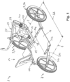
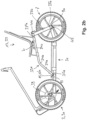
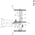
- This tricycle 1 includes two front wheels 3, namely a left front wheel 3a and a right front wheel 3b. These rotate around an imaginary axis line 5.
- the tricycle includes a rear wheel 7, which is also referred to below as the rear wheel 7, which rotates about an imaginary axis line 9.
- a pair of rear wheels can in principle also be provided with two rear wheels sitting in close proximity to one another and rotating about a common axis of rotation (in the manner of a twin wheel or pair of wheels), which, due to their small distance compared to the distance between the two front wheels 3, i.e. 3a, 3b act like a single or a common wheel.
- this structure with two rear wheels is not according to the invention.
- the distance between the front axle line 5 and the rear axle line 9 forms the axle distance AA of the tricycle.
- the tricycle comprises a frame 11, via which the respective front wheel 3a or 3b and also the rear wheel 7 are held, namely via the bearings in such a way that the wheels can rotate with as little friction as possible.
- a vertical central longitudinal plane M3a runs through the left front wheel 3a
- a vertical central longitudinal plane M3b runs through the right front wheel 3b
- the two central longitudinal planes M3a and M3b always run parallel to one another and, when exiting straight, also parallel to the others defined below Figure 3 Longitudinal planes running perpendicular to the plane of the drawing.
- a vertical central longitudinal plane M7 is defined by the rear wheel 7.
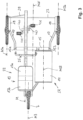
- a floor, a floor surface, or a floor area or load floor 14 or the like is provided, which, for example, has a leading anchoring point 114a and a trailing fastening point 114b (see Figure 2a and 2 B ) can be anchored to a load carrier 31, which will be discussed later, preferably at a short distance above it.
- a load carrier 31 which will be discussed later, preferably at a short distance above it.
- This can be, for example, a load floor that is at least rectangular in plan view or approximately shaped, which can be made from a wide variety of materials and can also have a wide variety of shapes, for example can also be designed in a grid shape.
- hook devices or the like could also be provided in order to attach certain loads here.
- any items of luggage, but also beverage crates, can be placed on it and transported with the tricycle.
- further fixing devices can be provided in this storage space SR formed in this way, for example on the load floor 14 or on other fastening or hanging devices, in order to secure objects to be transported in this storage space SR against losing and slipping.
- the load floor 14 shown in the drawings has a leading and a trailing limiting web 14a to 14b which is intended to help prevent objects from slipping in the longitudinal direction when starting or braking. Holes, openings or other fastening means can also be provided there, for example to place straps and the like around the objects to be transported and secure them.
- the central plane M running centrally through the seat does not coincide with the vertical central plane M7, which runs centrally through the rear wheel 7.
- the chosen construction is such that the seat and thus its vertical central plane M is laterally offset from the vertical central plane M7 running through the rear wheel 7, namely not directed towards the storage space, but transversely to the central longitudinal plane MLE storage space.
- the seat 13 and thus its vertical central longitudinal plane M is laterally offset in the direction of that front wheel 3a whose front wheel central longitudinal plane M3a is at a smaller distance from the central longitudinal plane M7 through the rear wheel than the distance between this vertical central longitudinal plane M7 through the rear wheel 7 and the opposite front wheel 3b.
- the seat with the central longitudinal plane MLE is arranged laterally offset in the same direction in which the rear wheel 7 is laterally offset relative to the central longitudinal plane, the storage space SR lies opposite the rear wheel 7 and completely or predominantly to the seat 13 the side opposite the central longitudinal plane MLE, in particular from the top view Figure 3 can be seen. Since the rear wheel 7 is arranged virtually asymmetrically between the center of the storage space SR and the center of the seat 13, namely much closer to the central longitudinal plane M running through the seat 13 and thus further away from the storage space SR, this construction is fundamentally the same an optimal balance of weight distribution is achieved.
- the drawings also show the further structure of the frame 11, which is also sometimes referred to below as the frame structure or chassis 11.
- Tricycle is preferably provided that it comprises a cross member 15 as a central element, at the opposite side ends 15a of which, with a predominantly forward component (i.e. in the longitudinal direction), slightly outwardly diverging front supports 17 are provided, which lead to so-called wheel carriers 19.
- the two wheel carriers 19, one of which is assigned to the left wheel and the other to the right wheel 3a, 3b, and which are each arranged on the inside of the assigned wheel, are each together around a preferably vertical steering axis 21 in the illustration Figure 3 Can be pivoted to the left or right in order to be able to turn the tricycle to the left or right when cornering.
- a load carrier 31 (hereinafter also called load bar 31) leading to the rear wheel axle 9 is provided by the cross member 15 mentioned and is anchored or supported accordingly at its opposite ends.
- load carrier angles 141 that project transversely are preferably attached to the load carrier 31, for example welded, around the storage surface or to optimally support the load floor 14.
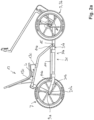
- the seat support arrangement 33 is provided, lying laterally offset essentially parallel to the load carrier 31, which starts from a leading support point 35a and is supported at the opposite trailing end on a support point 35b, on which the rear wheel axle 9a is preferably formed.
- the top tube 33a starting from the leading end 33'a, the top tube 33a initially runs in a first top tube section 34a with a stronger vertical component, in order to then merge at a transition region 34b into a second top tube section 34c, the orientation of which in the side view is such that its horizontal or The longitudinal extent is significantly larger than the vertical extent and therefore the vertical rise to its returning end 33"a is smaller
- this seat support arrangement 33 formed in this way could be designed to be rigid at the leading and trailing ends as well as at the transition from the top tube 33a to the rear tube 33b.
- the seat 13 on the top tube 33a that is, in the exemplary embodiment shown, at least in the second top tube section 34c, could be adjusted in the longitudinal direction L, as shown by the arrow illustration L in Figure 2a is indicated.
- a leading and a trailing seat holding section 13c which is firmly anchored and anchorable in a suitable manner on the top tube 33a, can be moved longitudinally in this area and held in the desired position by fixing devices (for example with an eccentric) that are not shown in detail.
- the lever for fixing a seat post on a bicycle can be anchored in an optimal position. This allows the distance to the bottom bracket housings 39 arranged axially in the area of the front wheel axle 5 with the two emanating from them Pedal levers 40 and the pedals 41 attached to them can be changed.
- the leading end 33'a of the top tube 33a can be pivoted on the cross member 15 by means of a first joint 43 provided there, at least in a sufficient angular range discussed below about a pivot axis running longitudinally to the cross member 15 and thus parallel to the axis line 5 or 9 .
- the trailing end 33"a of the top tube 33a is connected to one end of the rear tube 33b via a second joint 44, which in turn connects at least indirectly to the rear wheel axle 9a carrying the seat support arrangement 33 via a third joint 45.
- This arrangement basically results in a multi-point arrangement, in the exemplary embodiment shown a triangular arrangement with three joint points, which means in side view Figure 5a and 5b the frame 11 is ultimately changeable.
- the distances between the three joints 43, 44, 45 are shown as lines L33a, L33b and L31, respectively, regardless of the fact that, for example, the top tube 33a comprises two sections 34a, 34c which are oriented at an angle to one another and which are connected to one another via the transition region 34b mentioned.
- this down tube 31 has a down tube section 131b leading to the rear wheel axle 9a, which, with its straight running section in the exemplary embodiment shown, engages in a corresponding receptacle of a front down tube section 131a and is telescopically adjustable in length. Whether this involves pipe intervention is of secondary importance.
- the two lower tube sections 131a, 131b are longitudinally displaceable relative to one another and are guided captively into one another or against one another in such a way that they cannot come out of engagement and, on the other hand, overlap to a sufficient extent even at maximum longitudinal extent, so that both rear tube sections 131a, 131b can accommodate the weight to be carried.
- this support or load floor 14 is at its leading end, for example on a section of the trailing down tube section 131a at a support point 47 and its trailing end at another support point 48 is supported on the telescopic further down tube section 133b, but is longitudinally displaceable and not fixed.
- the frame construction can be, for example, from the in Figure 2a shown shorter longitudinal extension into the in Figure 7a shown larger longitudinal extent (i.e. from the position according to Figure 5a into the position according to Figure 5b ) can be changed, in which the center distance AA is increased and at the same time this seat support arrangement 33 with the seat 13 located on it is brought into a lower position, as can be seen from the illustrations.
- the two telescopic lower tube sections 133a, 133b can be fixed to one another in a non-displaceable manner by means of a fixing device 49, which is only shown abstractly in the drawings, in order to fix the respective desired sitting position.
- a fixing device is preferably provided for the seat support arrangement with the pipe sections connected to one another in an articulated manner.
- One of these fixing devices can be provided, for example, in the area of the joint 44 between the top tube 33a and the rear tube 33b.
- a further fixing device is provided in the area of the joint 45, namely at the trailing end of the rear tube 33b relative to the joint 45 on the rear wheel 7.
- fixing devices can be designed to be form-fitting and, for example, have stop limitations, in particular for the lowered seating position, so that further lowering beyond this form-fitting or stop-related end position is not possible.
- the mentioned fixing device 49 for the telescopic down tube sections 133a and 133b can also be designed to be form-fitting. All of these fixing devices mentioned, which are preferably formed in a form-fitting manner, can also be designed and implemented in a non-positive or form-fitting and force-fitting manner. Locking and fixing devices with the same effect are possible and conceivable, in particular to keep the sitting position in the desired position and to absorb and support the forces introduced into the frame.
- the overall arrangement - as has already been shown - is designed in plan view in such a way that the length adjustment device for the load carrier 31 runs parallel to the central longitudinal plane MLE and also the top tube 33a and the rear tube 33b is arranged in plan view parallel to the central longitudinal plane MLE, so that the mentioned joint axes 43, 44, 45 are each aligned perpendicular to the central longitudinal plane.
Landscapes
- Engineering & Computer Science (AREA)
- Mechanical Engineering (AREA)
- Automatic Cycles, And Cycles In General (AREA)
Claims (14)
- Tricycle présentant les particularités suivantes :- il comporte deux roues avant (3 ; 3a, 3b) conjointement dirigeables, qui sont disposées symétriquement par rapport à un plan longitudinal médian (MLE) vertical traversant le tricycle et qui peuvent tourner sur une ligne d'axe de roue avant commune (5),- il comporte une roue arrière (7) pouvant tourner sur une ligne d'axe de roue arrière (9),- il comporte un siège (13),- il est également prévu un dispositif de réglage en hauteur du siège (13),- le dispositif de réglage en hauteur (13) comprend un dispositif de réglage en longueur grâce auquel de l'entraxe entre la ligne d'axe commune traversant les roues avant (3 ; 3a ; 3b) lors d'une avancée en ligne droite et la ligne d'axe (9) passant par la roue arrière (7), de préférence non dirigeable, est de grandeur modifiable et peut être fixé dans la position d'entraxe correspondante,caractérisé en ce que ladite roue arrière est disposée décentrée et agencée asymétriquement par rapport au plan longitudinal médian (MLE), et le siège est disposé en étant décalé et donc agencé asymétriquement par rapport au plan longitudinal médian ou disposé à au moins 75 % sur le même côté, eu égard au plan longitudinal médian central, que celui où se trouve la roue arrière décentrée.
- Tricycle selon la revendication 1, caractérisé en ce que le cadre du tricycle (11) présente un agencement de support de siège (33) qui comprend un tube supérieur (33a) qui est en appui, par le biais d'un tube arrière (33b), sur le cadre du tricycle (11) sous la forme de préférence d'une traverse (15) qui supporte au moins indirectement les roues avant (3) et/ou qui est en appui sur l'axe de roue arrière (9a).
- Tricycle selon la revendication 2, caractérisé en ce que le tube supérieur (33a) est en appui au moins indirectement, dans la zone antérieure, sur la traverse (15) et/ou sur les deux axes (5a) des deux roues avant (3).
- Tricycle selon la revendication 2 ou 3, caractérisé en ce que le tube supérieur (33a) est en appui au moins indirectement sur le tube inférieur ou support de charge (31) formant une partie du cadre du tricycle (11), de préférence par le biais de la traverse (15), et en ce que l'appui du tube supérieur (33a) est en appui au moins indirectement sur le tube inférieur (31) au moyen d'une première articulation (43a) et l'appui du tube arrière (33b) sur le tube inférieur (31), sur la partie restante du cadre du tricycle (11) et/ou sur l'axe de roue arrière (9a) est en appui au moyen d'un deuxième dispositif d'articulation (34b) formé au point de raccord entre le tube supérieur (33a) et le tube arrière (33b) par un troisième raccord articulé (45a).
- Tricycle selon la revendication 4, caractérisé en ce que le tube inférieur (31) est pourvu d'un dispositif de modification en longueur permettant de modifier en longueur la distance entre l'articulation antérieure (43) et l'articulation postérieure (45) et de la fixer à la longueur prédéfinie, moyennant quoi la position en hauteur du siège (13) peut être modifiée.
- Tricycle selon la revendication 4 ou 5, caractérisé en ce que le tube inférieur (31) peut être rentré et sorti de manière télescopique et fixé en position.
- Tricycle selon la revendication 6, caractérisé en ce que le tube inférieur (31) ou support de charge (31) présente une section antérieure (131a) et une section qui lui est postérieure (131b), la section antérieure (131a) étant supportée au moins indirectement au moyen des axes de roue avant (3') et la section postérieure (131b) étant supportée à son extrémité postérieure au moins indirectement au niveau de l'axe de roue arrière (9'), le support de chargement (14) étant supporté d'une part au niveau de la section antérieure (131a) du tube inférieure au moins au moyen de deux dispositifs de fixation (114a, 114b) et d'autre part au moyen de la section postérieure (131b) du tube inférieure, et l'un des deux dispositifs de fixation (114a ou 114b) étant supporté fixe sur une section (131a ou 131b) du tube inférieur et l'autre dispositif de fixation (114a ou 114b) étant supporté déplaçable sur l'autre section (131b ou 131a) du tube inférieur.
- Tricycle selon l'une des revendications 1 à 7, présentant les particularités supplémentaires suivantes :- il comporte un espace porte-bagage (SR), et- l'espace porte-bagage (SR) est prévu totalement ou majoritairement sur le côté opposé au siège (13) et à la roue arrière (7), eu égard au plan longitudinal médian (MLE).
- Tricycle selon l'une des revendications 1 à 8, caractérisé en ce que la roue arrière (7) de préférence non dirigeable est disposée décentrée sur le cadre du tricycle (11) avec un décalage latéral par rapport au plan longitudinal médian (MLE).
- Tricycle selon l'une des revendications 1 à 9, caractérisé en ce que le siège (13) est disposé à au moins 80 %, 85 %, 90 % ou au moins 95 % ou 100 % du côté du plan longitudinal médian (MLE) sur lequel se trouve également la roue arrière (7) décentrée.
- Tricycle selon l'une des revendications 8 à 10, caractérisé en ce que l'espace porte-bagage (SR) est disposé à au moins 80 %, notamment à au moins 85 %, 90 %, 95 % ou 100 % du côté du plan longitudinal médian (MLE) qui est opposé au côté où se trouve la roue arrière (7).
- Tricycle selon l'une des revendications 8 à 11, caractérisé en ce que l'espace porte-bagage (SR) comporte des dispositifs de réception et/ou d'accrochage de biens à transporter.
- Tricycle selon l'une des revendications 8 à 12, caractérisé en ce que l'espace porte-bagage (SR) présente au moins un support de chargement (31) de préférence conçu sous la forme d'une plaque, d'une planche et/ou d'une grille ou d'une caissette.
- Tricycle selon l'une des revendications 1 à 13, caractérisé en ce que le siège (13) est fixé sur un cadre de vélo sur lequel il peut être réglé et verrouillé dans le sens longitudinal au moyen d'un dispositif de réglage.
Applications Claiming Priority (2)
| Application Number | Priority Date | Filing Date | Title |
|---|---|---|---|
| DE102019135265.7A DE102019135265B4 (de) | 2019-12-19 | 2019-12-19 | Dreirad |
| PCT/EP2020/082760 WO2021121851A1 (fr) | 2019-12-19 | 2020-11-19 | Tricycle |
Publications (3)
| Publication Number | Publication Date |
|---|---|
| EP4077112A1 EP4077112A1 (fr) | 2022-10-26 |
| EP4077112B1 true EP4077112B1 (fr) | 2023-12-20 |
| EP4077112C0 EP4077112C0 (fr) | 2023-12-20 |
Family
ID=73497790
Family Applications (1)
| Application Number | Title | Priority Date | Filing Date |
|---|---|---|---|
| EP20810959.5A Active EP4077112B1 (fr) | 2019-12-19 | 2020-11-19 | Tricycle |
Country Status (3)
| Country | Link |
|---|---|
| EP (1) | EP4077112B1 (fr) |
| DE (1) | DE102019135265B4 (fr) |
| WO (1) | WO2021121851A1 (fr) |
Family Cites Families (7)
| Publication number | Priority date | Publication date | Assignee | Title |
|---|---|---|---|---|
| US1446682A (en) | 1920-03-29 | 1923-02-27 | Judson Post | Wagon |
| FR823558A (fr) | 1937-05-25 | 1938-01-22 | Bloc cadre châssis à trois roues permettant la traction mécanique des pousse-pousse | |
| GB664012A (en) | 1949-09-20 | 1951-01-02 | Jack Geoffrey Fowler | Improvements in or relating to pedal tricycles |
| CN101698420A (zh) * | 2009-09-18 | 2010-04-28 | 郝明刚 | 三角智动变形机动车 |
| WO2013066804A1 (fr) * | 2011-10-31 | 2013-05-10 | Tanom Motors, LLC | Systèmes et appareil pour véhicule à trois roues |
| CN203142891U (zh) * | 2013-01-05 | 2013-08-21 | 高尚义 | 一种三轮车 |
| US8840131B1 (en) * | 2013-03-15 | 2014-09-23 | Planet Rider LLC | Three-wheeled vehicle |
-
2019
- 2019-12-19 DE DE102019135265.7A patent/DE102019135265B4/de active Active
-
2020
- 2020-11-19 EP EP20810959.5A patent/EP4077112B1/fr active Active
- 2020-11-19 WO PCT/EP2020/082760 patent/WO2021121851A1/fr not_active Ceased
Also Published As
| Publication number | Publication date |
|---|---|
| DE102019135265B4 (de) | 2021-12-02 |
| EP4077112A1 (fr) | 2022-10-26 |
| WO2021121851A1 (fr) | 2021-06-24 |
| EP4077112C0 (fr) | 2023-12-20 |
| DE102019135265A1 (de) | 2021-06-24 |
Similar Documents
| Publication | Publication Date | Title |
|---|---|---|
| DE102019002456B4 (de) | Hinterradaufhängung für ein Fahrrad | |
| DE102011106561B4 (de) | Lasten- und/oder Transportroller | |
| EP2768722B1 (fr) | Bicyclette compacte pliable | |
| EP1993899B1 (fr) | Vehicule s'inclinant dans les virages, notamment tricycle | |
| DE212009000010U1 (de) | Faltbares Liegefahrzeug | |
| DE2707562A1 (de) | Plattform-stabilisiertes, kurvenneigendes motorfahrzeug | |
| AT513539B1 (de) | Fahrzeug mit verstellbarer Radachse | |
| DE102004025884B4 (de) | Teleskopisches Fahrrad | |
| DE102013108112A1 (de) | Klappbares Transportrad | |
| DD154090A5 (de) | Veloziped | |
| DE102019003129B3 (de) | DREIRÄDRIGES ELEKTROFAHRZEUG NACH EG-FAHRZEUGKLASSE L2e-U | |
| EP4558386A1 (fr) | Véhicule à roues alignées | |
| DE29701641U1 (de) | Faltrad mit kleinen Rädern oder Rollen | |
| EP4077112B1 (fr) | Tricycle | |
| DE10204311C2 (de) | Fahrrad mit Staubehälter | |
| DE202017103729U1 (de) | Personen-, Lasten- und Transportroller | |
| EP0892733B1 (fr) | Structure du cadre d'une bicyclette a plusieurs places et a deux essieux | |
| EP3819200B1 (fr) | Tandem combiné | |
| DE102006062678B4 (de) | Kurvenneigendes Dreirad | |
| DE102011054270A1 (de) | Laufrad | |
| EP2665637A2 (fr) | Système de roue porteuse pour une bicyclette | |
| DE10220241C1 (de) | Klappfahrrad | |
| EP4480801A1 (fr) | Cadre de bicyclette modulaire pour vélo électrique | |
| DE202021101811U1 (de) | Fahrzeugrahmen für ein vierrädriges mit Muskelkraft betreibbares Fahrzeug und Fahrzeug | |
| DE102023133878A1 (de) | Einstellbarer zweiradrahmen |
Legal Events
| Date | Code | Title | Description |
|---|---|---|---|
| STAA | Information on the status of an ep patent application or granted ep patent |
Free format text: STATUS: UNKNOWN |
|
| STAA | Information on the status of an ep patent application or granted ep patent |
Free format text: STATUS: THE INTERNATIONAL PUBLICATION HAS BEEN MADE |
|
| PUAI | Public reference made under article 153(3) epc to a published international application that has entered the european phase |
Free format text: ORIGINAL CODE: 0009012 |
|
| STAA | Information on the status of an ep patent application or granted ep patent |
Free format text: STATUS: REQUEST FOR EXAMINATION WAS MADE |
|
| 17P | Request for examination filed |
Effective date: 20220317 |
|
| AK | Designated contracting states |
Kind code of ref document: A1 Designated state(s): AL AT BE BG CH CY CZ DE DK EE ES FI FR GB GR HR HU IE IS IT LI LT LU LV MC MK MT NL NO PL PT RO RS SE SI SK SM TR |
|
| DAV | Request for validation of the european patent (deleted) | ||
| DAX | Request for extension of the european patent (deleted) | ||
| GRAP | Despatch of communication of intention to grant a patent |
Free format text: ORIGINAL CODE: EPIDOSNIGR1 |
|
| STAA | Information on the status of an ep patent application or granted ep patent |
Free format text: STATUS: GRANT OF PATENT IS INTENDED |
|
| INTG | Intention to grant announced |
Effective date: 20230720 |
|
| GRAS | Grant fee paid |
Free format text: ORIGINAL CODE: EPIDOSNIGR3 |
|
| GRAA | (expected) grant |
Free format text: ORIGINAL CODE: 0009210 |
|
| STAA | Information on the status of an ep patent application or granted ep patent |
Free format text: STATUS: THE PATENT HAS BEEN GRANTED |
|
| AK | Designated contracting states |
Kind code of ref document: B1 Designated state(s): AL AT BE BG CH CY CZ DE DK EE ES FI FR GB GR HR HU IE IS IT LI LT LU LV MC MK MT NL NO PL PT RO RS SE SI SK SM TR |
|
| REG | Reference to a national code |
Ref country code: GB Ref legal event code: FG4D Free format text: NOT ENGLISH |
|
| REG | Reference to a national code |
Ref country code: CH Ref legal event code: EP |
|
| REG | Reference to a national code |
Ref country code: DE Ref legal event code: R096 Ref document number: 502020006472 Country of ref document: DE |
|
| REG | Reference to a national code |
Ref country code: IE Ref legal event code: FG4D Free format text: LANGUAGE OF EP DOCUMENT: GERMAN |
|
| U01 | Request for unitary effect filed |
Effective date: 20240111 |
|
| U07 | Unitary effect registered |
Designated state(s): AT BE BG DE DK EE FI FR IT LT LU LV MT NL PT SE SI Effective date: 20240119 |
|
| PG25 | Lapsed in a contracting state [announced via postgrant information from national office to epo] |
Ref country code: GR Free format text: LAPSE BECAUSE OF FAILURE TO SUBMIT A TRANSLATION OF THE DESCRIPTION OR TO PAY THE FEE WITHIN THE PRESCRIBED TIME-LIMIT Effective date: 20240321 |
|
| PG25 | Lapsed in a contracting state [announced via postgrant information from national office to epo] |
Ref country code: ES Free format text: LAPSE BECAUSE OF FAILURE TO SUBMIT A TRANSLATION OF THE DESCRIPTION OR TO PAY THE FEE WITHIN THE PRESCRIBED TIME-LIMIT Effective date: 20231220 |
|
| PG25 | Lapsed in a contracting state [announced via postgrant information from national office to epo] |
Ref country code: GR Free format text: LAPSE BECAUSE OF FAILURE TO SUBMIT A TRANSLATION OF THE DESCRIPTION OR TO PAY THE FEE WITHIN THE PRESCRIBED TIME-LIMIT Effective date: 20240321 Ref country code: ES Free format text: LAPSE BECAUSE OF FAILURE TO SUBMIT A TRANSLATION OF THE DESCRIPTION OR TO PAY THE FEE WITHIN THE PRESCRIBED TIME-LIMIT Effective date: 20231220 |
|
| PG25 | Lapsed in a contracting state [announced via postgrant information from national office to epo] |
Ref country code: RS Free format text: LAPSE BECAUSE OF FAILURE TO SUBMIT A TRANSLATION OF THE DESCRIPTION OR TO PAY THE FEE WITHIN THE PRESCRIBED TIME-LIMIT Effective date: 20231220 Ref country code: NO Free format text: LAPSE BECAUSE OF FAILURE TO SUBMIT A TRANSLATION OF THE DESCRIPTION OR TO PAY THE FEE WITHIN THE PRESCRIBED TIME-LIMIT Effective date: 20240320 Ref country code: HR Free format text: LAPSE BECAUSE OF FAILURE TO SUBMIT A TRANSLATION OF THE DESCRIPTION OR TO PAY THE FEE WITHIN THE PRESCRIBED TIME-LIMIT Effective date: 20231220 |
|
| PG25 | Lapsed in a contracting state [announced via postgrant information from national office to epo] |
Ref country code: IS Free format text: LAPSE BECAUSE OF FAILURE TO SUBMIT A TRANSLATION OF THE DESCRIPTION OR TO PAY THE FEE WITHIN THE PRESCRIBED TIME-LIMIT Effective date: 20240420 |
|
| PG25 | Lapsed in a contracting state [announced via postgrant information from national office to epo] |
Ref country code: CZ Free format text: LAPSE BECAUSE OF FAILURE TO SUBMIT A TRANSLATION OF THE DESCRIPTION OR TO PAY THE FEE WITHIN THE PRESCRIBED TIME-LIMIT Effective date: 20231220 |
|
| PG25 | Lapsed in a contracting state [announced via postgrant information from national office to epo] |
Ref country code: SK Free format text: LAPSE BECAUSE OF FAILURE TO SUBMIT A TRANSLATION OF THE DESCRIPTION OR TO PAY THE FEE WITHIN THE PRESCRIBED TIME-LIMIT Effective date: 20231220 |
|
| PG25 | Lapsed in a contracting state [announced via postgrant information from national office to epo] |
Ref country code: SM Free format text: LAPSE BECAUSE OF FAILURE TO SUBMIT A TRANSLATION OF THE DESCRIPTION OR TO PAY THE FEE WITHIN THE PRESCRIBED TIME-LIMIT Effective date: 20231220 Ref country code: SK Free format text: LAPSE BECAUSE OF FAILURE TO SUBMIT A TRANSLATION OF THE DESCRIPTION OR TO PAY THE FEE WITHIN THE PRESCRIBED TIME-LIMIT Effective date: 20231220 Ref country code: RO Free format text: LAPSE BECAUSE OF FAILURE TO SUBMIT A TRANSLATION OF THE DESCRIPTION OR TO PAY THE FEE WITHIN THE PRESCRIBED TIME-LIMIT Effective date: 20231220 Ref country code: IS Free format text: LAPSE BECAUSE OF FAILURE TO SUBMIT A TRANSLATION OF THE DESCRIPTION OR TO PAY THE FEE WITHIN THE PRESCRIBED TIME-LIMIT Effective date: 20240420 Ref country code: CZ Free format text: LAPSE BECAUSE OF FAILURE TO SUBMIT A TRANSLATION OF THE DESCRIPTION OR TO PAY THE FEE WITHIN THE PRESCRIBED TIME-LIMIT Effective date: 20231220 |
|
| PG25 | Lapsed in a contracting state [announced via postgrant information from national office to epo] |
Ref country code: PL Free format text: LAPSE BECAUSE OF FAILURE TO SUBMIT A TRANSLATION OF THE DESCRIPTION OR TO PAY THE FEE WITHIN THE PRESCRIBED TIME-LIMIT Effective date: 20231220 |
|
| PG25 | Lapsed in a contracting state [announced via postgrant information from national office to epo] |
Ref country code: PL Free format text: LAPSE BECAUSE OF FAILURE TO SUBMIT A TRANSLATION OF THE DESCRIPTION OR TO PAY THE FEE WITHIN THE PRESCRIBED TIME-LIMIT Effective date: 20231220 |
|
| REG | Reference to a national code |
Ref country code: DE Ref legal event code: R097 Ref document number: 502020006472 Country of ref document: DE |
|
| PLBE | No opposition filed within time limit |
Free format text: ORIGINAL CODE: 0009261 |
|
| STAA | Information on the status of an ep patent application or granted ep patent |
Free format text: STATUS: NO OPPOSITION FILED WITHIN TIME LIMIT |
|
| 26N | No opposition filed |
Effective date: 20240923 |
|
| U20 | Renewal fee for the european patent with unitary effect paid |
Year of fee payment: 5 Effective date: 20241125 |
|
| REG | Reference to a national code |
Ref country code: CH Ref legal event code: PL |
|
| PG25 | Lapsed in a contracting state [announced via postgrant information from national office to epo] |
Ref country code: MC Free format text: LAPSE BECAUSE OF FAILURE TO SUBMIT A TRANSLATION OF THE DESCRIPTION OR TO PAY THE FEE WITHIN THE PRESCRIBED TIME-LIMIT Effective date: 20231220 |
|
| REG | Reference to a national code |
Ref country code: CH Ref legal event code: PL |
|
| PG25 | Lapsed in a contracting state [announced via postgrant information from national office to epo] |
Ref country code: CH Free format text: LAPSE BECAUSE OF NON-PAYMENT OF DUE FEES Effective date: 20241130 |
|
| PG25 | Lapsed in a contracting state [announced via postgrant information from national office to epo] |
Ref country code: IE Free format text: LAPSE BECAUSE OF NON-PAYMENT OF DUE FEES Effective date: 20241119 |
|
| U20 | Renewal fee for the european patent with unitary effect paid |
Year of fee payment: 6 Effective date: 20251117 |
|
| PGFP | Annual fee paid to national office [announced via postgrant information from national office to epo] |
Ref country code: GB Payment date: 20251120 Year of fee payment: 6 |
|
| PG25 | Lapsed in a contracting state [announced via postgrant information from national office to epo] |
Ref country code: HU Free format text: LAPSE BECAUSE OF FAILURE TO SUBMIT A TRANSLATION OF THE DESCRIPTION OR TO PAY THE FEE WITHIN THE PRESCRIBED TIME-LIMIT; INVALID AB INITIO Effective date: 20201119 |
|
| PG25 | Lapsed in a contracting state [announced via postgrant information from national office to epo] |
Ref country code: CY Free format text: LAPSE BECAUSE OF FAILURE TO SUBMIT A TRANSLATION OF THE DESCRIPTION OR TO PAY THE FEE WITHIN THE PRESCRIBED TIME-LIMIT; INVALID AB INITIO Effective date: 20201119 |