EP4077112B1 - Tricycle - Google Patents
Tricycle Download PDFInfo
- Publication number
- EP4077112B1 EP4077112B1 EP20810959.5A EP20810959A EP4077112B1 EP 4077112 B1 EP4077112 B1 EP 4077112B1 EP 20810959 A EP20810959 A EP 20810959A EP 4077112 B1 EP4077112 B1 EP 4077112B1
- Authority
- EP
- European Patent Office
- Prior art keywords
- tricycle
- rear wheel
- down tube
- seat
- central longitudinal
- Prior art date
- Legal status (The legal status is an assumption and is not a legal conclusion. Google has not performed a legal analysis and makes no representation as to the accuracy of the status listed.)
- Active
Links
- 238000010276 construction Methods 0.000 description 13
- 239000000969 carrier Substances 0.000 description 3
- 230000007704 transition Effects 0.000 description 3
- 238000004873 anchoring Methods 0.000 description 2
- 230000008878 coupling Effects 0.000 description 2
- 238000010168 coupling process Methods 0.000 description 2
- 238000005859 coupling reaction Methods 0.000 description 2
- 210000003205 muscle Anatomy 0.000 description 2
- 235000013361 beverage Nutrition 0.000 description 1
- 230000000694 effects Effects 0.000 description 1
- 230000033001 locomotion Effects 0.000 description 1
- 239000000463 material Substances 0.000 description 1
- 230000000630 rising effect Effects 0.000 description 1
- 230000029305 taxis Effects 0.000 description 1
Images


Classifications
-
- B—PERFORMING OPERATIONS; TRANSPORTING
- B62—LAND VEHICLES FOR TRAVELLING OTHERWISE THAN ON RAILS
- B62K—CYCLES; CYCLE FRAMES; CYCLE STEERING DEVICES; RIDER-OPERATED TERMINAL CONTROLS SPECIALLY ADAPTED FOR CYCLES; CYCLE AXLE SUSPENSIONS; CYCLE SIDE-CARS, FORECARS, OR THE LIKE
- B62K7/00—Freight- or passenger-carrying cycles
- B62K7/02—Frames
- B62K7/04—Frames having a carrying platform
-
- B—PERFORMING OPERATIONS; TRANSPORTING
- B62—LAND VEHICLES FOR TRAVELLING OTHERWISE THAN ON RAILS
- B62K—CYCLES; CYCLE FRAMES; CYCLE STEERING DEVICES; RIDER-OPERATED TERMINAL CONTROLS SPECIALLY ADAPTED FOR CYCLES; CYCLE AXLE SUSPENSIONS; CYCLE SIDE-CARS, FORECARS, OR THE LIKE
- B62K15/00—Collapsible or foldable cycles
-
- B—PERFORMING OPERATIONS; TRANSPORTING
- B62—LAND VEHICLES FOR TRAVELLING OTHERWISE THAN ON RAILS
- B62K—CYCLES; CYCLE FRAMES; CYCLE STEERING DEVICES; RIDER-OPERATED TERMINAL CONTROLS SPECIALLY ADAPTED FOR CYCLES; CYCLE AXLE SUSPENSIONS; CYCLE SIDE-CARS, FORECARS, OR THE LIKE
- B62K5/00—Cycles with handlebars, equipped with three or more main road wheels
- B62K5/02—Tricycles
- B62K5/05—Tricycles characterised by a single rear wheel
-
- B—PERFORMING OPERATIONS; TRANSPORTING
- B62—LAND VEHICLES FOR TRAVELLING OTHERWISE THAN ON RAILS
- B62K—CYCLES; CYCLE FRAMES; CYCLE STEERING DEVICES; RIDER-OPERATED TERMINAL CONTROLS SPECIALLY ADAPTED FOR CYCLES; CYCLE AXLE SUSPENSIONS; CYCLE SIDE-CARS, FORECARS, OR THE LIKE
- B62K5/00—Cycles with handlebars, equipped with three or more main road wheels
- B62K5/08—Cycles with handlebars, equipped with three or more main road wheels with steering devices acting on two or more wheels
-
- B—PERFORMING OPERATIONS; TRANSPORTING
- B62—LAND VEHICLES FOR TRAVELLING OTHERWISE THAN ON RAILS
- B62K—CYCLES; CYCLE FRAMES; CYCLE STEERING DEVICES; RIDER-OPERATED TERMINAL CONTROLS SPECIALLY ADAPTED FOR CYCLES; CYCLE AXLE SUSPENSIONS; CYCLE SIDE-CARS, FORECARS, OR THE LIKE
- B62K5/00—Cycles with handlebars, equipped with three or more main road wheels
- B62K5/003—Cycles with four or more wheels, specially adapted for disabled riders, e.g. personal mobility type vehicles with four wheels
Definitions
- the invention relates to a tricycle according to the preamble of claim 1.
- Document US2014/262578A1 shows the preamble of claim 1.
- a tricycle is usually understood to mean a vehicle with three wheels.
- Such tricycles are also well known as motor vehicles, for example, usually with a rear axle with two rear wheels arranged laterally offset from one another and a steerable front wheel, which is arranged symmetrically to the rear wheels in the central longitudinal plane.
- steerable front wheel is similar a motorcycle, whereas the rear axle construction and the drive itself are more comparable to a four-wheeled motor vehicle.
- motorcycles or scooters are also known that are equipped with a side boom.
- people often talk about sidecar machines.
- These are conventional vehicles (motorcycles, scooters) with a front wheel and a rear wheel, which are only equipped with a sidecar on one side for expansion, which is supported by another laterally offset rear wheel.
- a tricycle is out of the GB 664 012 A as known. It has a rear axle with two rear wheels that are laterally offset from one another. A steerable front wheel can be swiveled via a handlebar to enable cornering. Furthermore, the previously known tricycle has a saddle and a conventional pedal device, via which the rear axle and thus the two laterally offset rear wheels can be driven by means of a gear and a rotating chain.
- the arrangement of the saddle, the pedals, the handlebar and the front wheel are laterally asymmetrically offset from a vertical longitudinal plane, so that a larger distance to the more distant rear wheel is formed on one long side.
- This room houses a sidecar or sidecar.
- a tricycle with an asymmetrically arranged vertical longitudinal plane in which the central part of the bicycle frame are arranged with a pedal device and a steerable front wheel, is also from the FR 823 558 A refer to.
- the object of the present invention is to create an improved tricycle, which in particular also has advantages in use.
- the tricycle according to the invention can preferably be a tricycle that can be driven by muscle power, which, like conventional bicycles, is usually driven via pedals and a bottom bracket, for example via a chain with or without another gear shift, etc.
- the tricycle according to the invention can be equipped with an additional electric motor, similar to an e-bike, which can be switched on if necessary, for example by pedaling.
- the tricycle according to the invention can also be equipped with an electric motor and can only be driven by an electric motor, i.e. without the possibility of being able to drive the tricycle using muscle power.
- the tricycle according to the invention is characterized in that the tricycle not only has the advantages described due to its structural features, but also alternatively or additionally also has the possibility of changing the sitting position.
- the seating position is adjustable relative to the tread of the wheels, i.e. at least with a component in the vertical direction and thus at different heights and/or at least with a component in the longitudinal or horizontal direction in a different longitudinal position with respect to the arrangement the wheels are adjustable.
- an adjustment of the seat relative to the wheels can be easily carried out, preferably in that the seat is adjustable and attached to a top tube that runs at least predominantly in the longitudinal direction of the tricycle can be locked at any desired location.
- An adjustment in the vertical direction is preferably achieved by the bicycle frame having a top tube and rear tube construction.
- the top tube and the rear tube are connected via a joint that is usually located at the top, which means that the angle setting between the top and rear tubes can be changed.
- the top tube is supported in the front area of the remaining tricycle frame and the rear tube in a rear area of the remaining tricycle frame, again via an articulated connection.
- Between these two joint connections i.e. the joint connection at the leading end of the top tube or the joint connection at the trailing end of the rear tube
- there are at least indirectly connected to each other via a tricycle frame construction which is provided with an adjustment device. This allows the distance between the two mentioned joint connections to be set to different sizes and fixed at this size.
- This length adjustment device can also be referred to as a down tube or down tube construction. This creates a triangular construction in a side view, the two legs (top tube and rear tube) running with vertical components are articulated to one another at one point and the opposite free leg ends of which are then each articulated to the down tube forming the length adjustment device, at least indirectly.
- the down tube has a length adjustment device. If the down tube is lengthened and the distance between the axes of rotation of the front wheels and the at least one rear wheel is increased, the position of the seat is lowered. If the length of the down tube is shortened again, the sitting position on the top tube is raised.
- the top tube and the rear tube both of which are connected to one another in an articulated manner at the top, and the down tube leading to the triangular solution in a side view result in a triangular geometry in a side view, but in a top view transverse to the central longitudinal plane of the The tricycle is offset.
- the down tube preferably runs below the load floor or the storage space for holding loads and objects, whereas the top tube carrying the seat and the rear tube are arranged together laterally offset from it.
- the rear tube is held on one side on the axis of rotation of the rear wheel, whereas the mentioned load-bearing down tube is mounted on the opposite side of the rear wheel.
- the handlebar can also be individually adjusted around a horizontal axis in accordance with the sitting position or preferably in accordance with the sitting position, so that its position, ie the position of the handlebar, can be brought into a preferred position, relative to the respective sitting position.
- the tricycle according to the invention is preferably further designed in such a way that, on the one hand, it optimally absorbs possible tilting moments, but on the other hand it also creates a comfortable application option, for example, to carry certain objects, loads, etc. with you.
- the tricycle is preferably characterized by the fact that in addition to two front wheels connected to each other by a front axle, a rear wheel is also provided.
- the rear wheel can in principle also be replaced by a pair of rear wheels, the two wheels of which, in contrast to the two front wheels, are then arranged more or less next to each other at a smaller or small distance from one another and thus essentially as a single rear wheel or single rear wheel arrangement with a pair of tires or a so-called twin tire acts or can be understood, but does not form part of the invention.
- This rear wheel construction is designed in such a way that the rear wheel is not arranged in the vertical central longitudinal plane of the vehicle, i.e. not centrally between the two front wheels, but off-center, i.e. asymmetrically.
- one rear wheel is arranged laterally offset from the vertical central longitudinal plane to one of the two front wheels, i.e. the lateral distance between the rear wheel and one of the front wheels is significantly smaller than the lateral distance between the rear wheel and the other front wheel.
- a support floor or generally a storage area or storage area is provided, which can be designed, for example, in the shape of a board or grid or, for example, as a receiving tray, etc.
- a box with a lid can be provided here in which items can be stored. There are no restrictions in this respect.
- a tray-shaped support floor can be provided, which, for example, has a boundary edge in the direction of travel and opposite thereto, which serves as a support edge for objects that could possibly easily slip in the longitudinal direction of the support floor on the support floor formed in this way when the tricycle starts or brakes.
- receiving openings or anchors can then be provided, through which, for example, straps are passed, which serve to secure the objects placed thereon. This offers a wide range of possible uses without any restrictions.
- the support base is preferably supported on part of the tricycle frame.
- the seat arrangement can be provided symmetrically to the vertical rear wheel longitudinal plane accommodating the rear wheel.
- the front bottom bracket and the pedal levers and pedals attached to it would then preferably be arranged symmetrically to this vertical rear wheel longitudinal plane.
- the seat arrangement is arranged not only asymmetrically to the vertical central longitudinal plane running through the tricycle, but also asymmetrically to the rear wheel longitudinal plane, preferably with a lateral offset in the direction that is directed away from the storage space mentioned is, i.e. it is offset from the vertical central longitudinal plane of symmetry. This further increases the space provided for storage space.
- This tricycle 1 includes two front wheels 3, namely a left front wheel 3a and a right front wheel 3b. These rotate around an imaginary axis line 5.
- the tricycle includes a rear wheel 7, which is also referred to below as the rear wheel 7, which rotates about an imaginary axis line 9.
- a pair of rear wheels can in principle also be provided with two rear wheels sitting in close proximity to one another and rotating about a common axis of rotation (in the manner of a twin wheel or pair of wheels), which, due to their small distance compared to the distance between the two front wheels 3, i.e. 3a, 3b act like a single or a common wheel.
- this structure with two rear wheels is not according to the invention.
- the distance between the front axle line 5 and the rear axle line 9 forms the axle distance AA of the tricycle.
- the tricycle comprises a frame 11, via which the respective front wheel 3a or 3b and also the rear wheel 7 are held, namely via the bearings in such a way that the wheels can rotate with as little friction as possible.
- a vertical central longitudinal plane M3a runs through the left front wheel 3a
- a vertical central longitudinal plane M3b runs through the right front wheel 3b
- the two central longitudinal planes M3a and M3b always run parallel to one another and, when exiting straight, also parallel to the others defined below Figure 3 Longitudinal planes running perpendicular to the plane of the drawing.
- a vertical central longitudinal plane M7 is defined by the rear wheel 7.
- a floor, a floor surface, or a floor area or load floor 14 or the like is provided, which, for example, has a leading anchoring point 114a and a trailing fastening point 114b (see Figure 2a and 2 B ) can be anchored to a load carrier 31, which will be discussed later, preferably at a short distance above it.
- a load carrier 31 which will be discussed later, preferably at a short distance above it.
- This can be, for example, a load floor that is at least rectangular in plan view or approximately shaped, which can be made from a wide variety of materials and can also have a wide variety of shapes, for example can also be designed in a grid shape.
- hook devices or the like could also be provided in order to attach certain loads here.
- any items of luggage, but also beverage crates, can be placed on it and transported with the tricycle.
- further fixing devices can be provided in this storage space SR formed in this way, for example on the load floor 14 or on other fastening or hanging devices, in order to secure objects to be transported in this storage space SR against losing and slipping.
- the load floor 14 shown in the drawings has a leading and a trailing limiting web 14a to 14b which is intended to help prevent objects from slipping in the longitudinal direction when starting or braking. Holes, openings or other fastening means can also be provided there, for example to place straps and the like around the objects to be transported and secure them.
- the central plane M running centrally through the seat does not coincide with the vertical central plane M7, which runs centrally through the rear wheel 7.
- the chosen construction is such that the seat and thus its vertical central plane M is laterally offset from the vertical central plane M7 running through the rear wheel 7, namely not directed towards the storage space, but transversely to the central longitudinal plane MLE storage space.
- the seat 13 and thus its vertical central longitudinal plane M is laterally offset in the direction of that front wheel 3a whose front wheel central longitudinal plane M3a is at a smaller distance from the central longitudinal plane M7 through the rear wheel than the distance between this vertical central longitudinal plane M7 through the rear wheel 7 and the opposite front wheel 3b.
- the seat with the central longitudinal plane MLE is arranged laterally offset in the same direction in which the rear wheel 7 is laterally offset relative to the central longitudinal plane, the storage space SR lies opposite the rear wheel 7 and completely or predominantly to the seat 13 the side opposite the central longitudinal plane MLE, in particular from the top view Figure 3 can be seen. Since the rear wheel 7 is arranged virtually asymmetrically between the center of the storage space SR and the center of the seat 13, namely much closer to the central longitudinal plane M running through the seat 13 and thus further away from the storage space SR, this construction is fundamentally the same an optimal balance of weight distribution is achieved.
- the drawings also show the further structure of the frame 11, which is also sometimes referred to below as the frame structure or chassis 11.
- Tricycle is preferably provided that it comprises a cross member 15 as a central element, at the opposite side ends 15a of which, with a predominantly forward component (i.e. in the longitudinal direction), slightly outwardly diverging front supports 17 are provided, which lead to so-called wheel carriers 19.
- the two wheel carriers 19, one of which is assigned to the left wheel and the other to the right wheel 3a, 3b, and which are each arranged on the inside of the assigned wheel, are each together around a preferably vertical steering axis 21 in the illustration Figure 3 Can be pivoted to the left or right in order to be able to turn the tricycle to the left or right when cornering.
- a load carrier 31 (hereinafter also called load bar 31) leading to the rear wheel axle 9 is provided by the cross member 15 mentioned and is anchored or supported accordingly at its opposite ends.
- load carrier angles 141 that project transversely are preferably attached to the load carrier 31, for example welded, around the storage surface or to optimally support the load floor 14.
- the seat support arrangement 33 is provided, lying laterally offset essentially parallel to the load carrier 31, which starts from a leading support point 35a and is supported at the opposite trailing end on a support point 35b, on which the rear wheel axle 9a is preferably formed.
- the top tube 33a starting from the leading end 33'a, the top tube 33a initially runs in a first top tube section 34a with a stronger vertical component, in order to then merge at a transition region 34b into a second top tube section 34c, the orientation of which in the side view is such that its horizontal or The longitudinal extent is significantly larger than the vertical extent and therefore the vertical rise to its returning end 33"a is smaller
- this seat support arrangement 33 formed in this way could be designed to be rigid at the leading and trailing ends as well as at the transition from the top tube 33a to the rear tube 33b.
- the seat 13 on the top tube 33a that is, in the exemplary embodiment shown, at least in the second top tube section 34c, could be adjusted in the longitudinal direction L, as shown by the arrow illustration L in Figure 2a is indicated.
- a leading and a trailing seat holding section 13c which is firmly anchored and anchorable in a suitable manner on the top tube 33a, can be moved longitudinally in this area and held in the desired position by fixing devices (for example with an eccentric) that are not shown in detail.
- the lever for fixing a seat post on a bicycle can be anchored in an optimal position. This allows the distance to the bottom bracket housings 39 arranged axially in the area of the front wheel axle 5 with the two emanating from them Pedal levers 40 and the pedals 41 attached to them can be changed.
- the leading end 33'a of the top tube 33a can be pivoted on the cross member 15 by means of a first joint 43 provided there, at least in a sufficient angular range discussed below about a pivot axis running longitudinally to the cross member 15 and thus parallel to the axis line 5 or 9 .
- the trailing end 33"a of the top tube 33a is connected to one end of the rear tube 33b via a second joint 44, which in turn connects at least indirectly to the rear wheel axle 9a carrying the seat support arrangement 33 via a third joint 45.
- This arrangement basically results in a multi-point arrangement, in the exemplary embodiment shown a triangular arrangement with three joint points, which means in side view Figure 5a and 5b the frame 11 is ultimately changeable.
- the distances between the three joints 43, 44, 45 are shown as lines L33a, L33b and L31, respectively, regardless of the fact that, for example, the top tube 33a comprises two sections 34a, 34c which are oriented at an angle to one another and which are connected to one another via the transition region 34b mentioned.
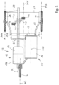
- this down tube 31 has a down tube section 131b leading to the rear wheel axle 9a, which, with its straight running section in the exemplary embodiment shown, engages in a corresponding receptacle of a front down tube section 131a and is telescopically adjustable in length. Whether this involves pipe intervention is of secondary importance.
- the two lower tube sections 131a, 131b are longitudinally displaceable relative to one another and are guided captively into one another or against one another in such a way that they cannot come out of engagement and, on the other hand, overlap to a sufficient extent even at maximum longitudinal extent, so that both rear tube sections 131a, 131b can accommodate the weight to be carried.
- this support or load floor 14 is at its leading end, for example on a section of the trailing down tube section 131a at a support point 47 and its trailing end at another support point 48 is supported on the telescopic further down tube section 133b, but is longitudinally displaceable and not fixed.
- the frame construction can be, for example, from the in Figure 2a shown shorter longitudinal extension into the in Figure 7a shown larger longitudinal extent (i.e. from the position according to Figure 5a into the position according to Figure 5b ) can be changed, in which the center distance AA is increased and at the same time this seat support arrangement 33 with the seat 13 located on it is brought into a lower position, as can be seen from the illustrations.
- the two telescopic lower tube sections 133a, 133b can be fixed to one another in a non-displaceable manner by means of a fixing device 49, which is only shown abstractly in the drawings, in order to fix the respective desired sitting position.
- a fixing device is preferably provided for the seat support arrangement with the pipe sections connected to one another in an articulated manner.
- One of these fixing devices can be provided, for example, in the area of the joint 44 between the top tube 33a and the rear tube 33b.
- a further fixing device is provided in the area of the joint 45, namely at the trailing end of the rear tube 33b relative to the joint 45 on the rear wheel 7.
- fixing devices can be designed to be form-fitting and, for example, have stop limitations, in particular for the lowered seating position, so that further lowering beyond this form-fitting or stop-related end position is not possible.
- the mentioned fixing device 49 for the telescopic down tube sections 133a and 133b can also be designed to be form-fitting. All of these fixing devices mentioned, which are preferably formed in a form-fitting manner, can also be designed and implemented in a non-positive or form-fitting and force-fitting manner. Locking and fixing devices with the same effect are possible and conceivable, in particular to keep the sitting position in the desired position and to absorb and support the forces introduced into the frame.
- the overall arrangement - as has already been shown - is designed in plan view in such a way that the length adjustment device for the load carrier 31 runs parallel to the central longitudinal plane MLE and also the top tube 33a and the rear tube 33b is arranged in plan view parallel to the central longitudinal plane MLE, so that the mentioned joint axes 43, 44, 45 are each aligned perpendicular to the central longitudinal plane.
Description
Die Erfindung betrifft ein Dreirad nach dem Oberbegriff des Anspruchs 1. Dokument
Unter einem Dreirad wird üblicherweise ein Fahrzeug mit drei Rädern verstanden. Derartige Dreiräder sind beispielsweise auch als Kraftfahrzeuge hinlänglich bekannt, üblicherweise mit einer Hinterachse mit zwei seitlich versetzt zueinander angeordneten Hinterrädern und einem lenkbaren Vorderrad, welches symmetrisch zu den Hinterrädern in der Mittellängsebene angeordnet ist.A tricycle is usually understood to mean a vehicle with three wheels. Such tricycles are also well known as motor vehicles, for example, usually with a rear axle with two rear wheels arranged laterally offset from one another and a steerable front wheel, which is arranged symmetrically to the rear wheels in the central longitudinal plane.
Derartige Dreiräder werden beispielsweise auch als Fahrradtaxis in einigen Großstädten eingesetzt, ebenso aber auch als Lastenfahrräder etc.Such tricycles are also used, for example, as bicycle taxis in some large cities, but also as cargo bikes, etc.
Ferner sind auch sogenannte "Trikes" bekannt, unter denen man üblicherweise ein offenes motorisiertes Straßenfahrzeug mit einem Vorderrad und zwei angetriebenen Hinterrädern versteht. Das lenkbare Vorderrad ist dabei ähnlich einem Motorrad ausgebildet, wohingegen die Hinterachskonstruktion und der Antrieb selbst eher mit einem vierrädrigen Kraftfahrzeug vergleichbar ist.Furthermore, so-called “trikes” are also known, which are usually understood to mean an open motorized road vehicle with a front wheel and two driven rear wheels. The steerable front wheel is similar a motorcycle, whereas the rear axle construction and the drive itself are more comparable to a four-wheeled motor vehicle.
Schließlich sind auch noch Motorräder oder Motorroller bekannt, die mit einem Seitenausleger ausgestattet sind. In diesem Zusammenhang wird häufig von Beiwagenmaschinen gesprochen. Dabei handelt es sich um herkömmliche ein Vorderrad und ein Hinterrad aufweisende Fahrzeuge (Motorrad, Roller), die zur Erweiterung lediglich an einer Seite mit einem Beiwagen ausgestattet sind, der durch ein weiteres seitlich versetztes Hinterrad abgestützt wird.Finally, motorcycles or scooters are also known that are equipped with a side boom. In this context, people often talk about sidecar machines. These are conventional vehicles (motorcycles, scooters) with a front wheel and a rear wheel, which are only equipped with a sidecar on one side for expansion, which is supported by another laterally offset rear wheel.
Ein Dreirad ist aus der
Die Anordnung des Sattels, der Pedale, der Lenkstange und des Vorderrades sind zu einer vertikalen Längsebene seitlich asymmetrisch versetzt, sodass auf einer Längsseite dazu ein größerer Abstandsraum zum entfernter liegenden Hinterrad gebildet ist. In diesem Raum ist ein Seitenwagen oder Beiwagen untergebracht.The arrangement of the saddle, the pedals, the handlebar and the front wheel are laterally asymmetrically offset from a vertical longitudinal plane, so that a larger distance to the more distant rear wheel is formed on one long side. This room houses a sidecar or sidecar.
Ein Dreirad mit asymmetrisch angeordneter vertikaler Längsebene, in der der zentrale Teil des Fahrradrahmens mit einer Pedaleinrichtung und einem lenkbaren Vorderrad angeordnet sind, ist zudem auch aus der
Aufgabe der vorliegenden Erfindung ist es, ein verbessertes Dreirad zu schaffen, welches insbesondere auch Vorteile im Einsatz aufweist.The object of the present invention is to create an improved tricycle, which in particular also has advantages in use.
Die Aufgabe wird erfindungsgemäß entsprechend den im Anspruch 1 angegebenen Merkmalen gelöst. Vorteilhafte Ausgestaltungen der Erfindung sind in den Unteransprüchen angegeben.The object is achieved according to the invention in accordance with the features specified in claim 1. Advantageous embodiments of the invention are specified in the subclaims.
Bei dem erfindungsgemäßen Dreirad kann es sich bevorzugt um ein mittels Muskelkraft antreibbares Dreirad handeln, welches üblicherweise, wie herkömmliche Fahrräder auch, über Pedale und ein Tretlager entsprechend angetrieben wird, beispielsweise über eine Kette mit oder ohne einerweiteren Gangschaltung etc.The tricycle according to the invention can preferably be a tricycle that can be driven by muscle power, which, like conventional bicycles, is usually driven via pedals and a bottom bracket, for example via a chain with or without another gear shift, etc.
Möglich ist aber auch, dass das erfindungsgemäße Dreirad vergleichbar einem E-Bike mit einem zusätzlichen Elektromotor ausgestattet ist, der bei Bedarf zugeschaltet werden kann, beispielsweise durch Treten. Schließlich kann das erfindungsgemäße Dreirad auch mit einem Elektromotor ausgestattet und nur elektromotorisch antreibbar sein, also ohne eine Möglichkeit das Dreirad mittels Muskelkraft antreiben zu können.However, it is also possible for the tricycle according to the invention to be equipped with an additional electric motor, similar to an e-bike, which can be switched on if necessary, for example by pedaling. Finally, the tricycle according to the invention can also be equipped with an electric motor and can only be driven by an electric motor, i.e. without the possibility of being able to drive the tricycle using muscle power.
Das erfindungsgemäße Dreirad zeichnet sich dadurch aus, dass das Dreirad nicht nur durch seine konstruktiven Gegebenheiten die geschilderten Vorteile aufweist, sondern alternativ oder ergänzend auch eine Möglichkeit aufweist, die Sitzposition zu verändern.The tricycle according to the invention is characterized in that the tricycle not only has the advantages described due to its structural features, but also alternatively or additionally also has the possibility of changing the sitting position.
Dabei ist im Rahmen der Erfindung vorgesehen, dass die Sitzposition gegenüber der Lauffläche der Räder, also zumindest mit einer Komponente in Vertikalrichtung und damit in unterschiedlicher Höhenlage einstellbar ist und/oder zumindest mit einer Komponente in Längs- oder Horizontalrichtung in unterschiedlicher Längslage bezogen auf die Anordnung der Räder einstellbar ist.It is provided within the scope of the invention that the seating position is adjustable relative to the tread of the wheels, i.e. at least with a component in the vertical direction and thus at different heights and/or at least with a component in the longitudinal or horizontal direction in a different longitudinal position with respect to the arrangement the wheels are adjustable.
Insbesondere eine Verstellung des Sitzes relativ zu den Rädern, also beispielsweise näher auf die Pedale zu oder weiter von diesen weg, kann einfach vorgenommen werden, bevorzugt dadurch, dass der Sitz an einem zumindest überwiegend in Längsrichtung des Dreirads verlaufenden Oberrohres in dessen Längsrichtung verstellbar und an einer beliebig gewünschten Stelle arretiert werden kann.In particular, an adjustment of the seat relative to the wheels, for example closer to the pedals or further away from them, can be easily carried out, preferably in that the seat is adjustable and attached to a top tube that runs at least predominantly in the longitudinal direction of the tricycle can be locked at any desired location.
Eine Verstellung in Vertikalrichtung wird bevorzugt dadurch erreicht, dass der Fahrradrahmen eine Oberrohr- und Hinterrohrkonstruktion aufweist. Dabei ist das Oberrohr und das Hinterrohr über ein in der Regel oben liegendes Gelenk verbunden, wodurch die Winkeleinstellung zwischen und Ober- und Hinterrohr veränderbar ist. Das Oberrohr ist im vorderen Bereich des verbleibenden Dreirad-Rahmens und das Hinterrohr in einem hinteren Bereich des verbleibenden Dreirad-Rahmens abgestützt, und zwar ebenfalls wieder über eine Gelenkverbindung. Zwischen diesen beiden Gelenkverbindungen (also die Gelenkverbindung am vorlaufenden Ende des Oberrohrs bzw. die Gelenkverbindung am nachlaufenden Ende des Hinterrohrs) sind zumindest mittelbar über eine Dreirad-Rahmen-Konstruktion fest miteinander verbunden, die doch mit einer Verstelleinrichtung versehen ist. Dadurch kann der Abstand zwischen den beiden erwähnten Gelenkverbindungen mit unterschiedlicher Größe eingestellt und in dieser Größe fixiert werden. Diese Längenverstelleinrichtung kann auch als Unterrohr oder Unterrohrkonstruktion bezeichnet werden. Dadurch wird in Seitenansicht eine Dreieckskonstruktion geschaffen, deren beide mit Vertikalkomponenten verlaufende Schenkel (Oberrohr und Hinterrohr) in einem Punkt gelenkig miteinander verbunden sind und deren jeweils gegenüberliegenden freien Schenkelenden dann jeweils gelenkig mit dem die Längenverstelleinrichtung bildenden Unterrohr verbunden sind, zumindest mittelbar.An adjustment in the vertical direction is preferably achieved by the bicycle frame having a top tube and rear tube construction. The top tube and the rear tube are connected via a joint that is usually located at the top, which means that the angle setting between the top and rear tubes can be changed. The top tube is supported in the front area of the remaining tricycle frame and the rear tube in a rear area of the remaining tricycle frame, again via an articulated connection. Between these two joint connections (i.e. the joint connection at the leading end of the top tube or the joint connection at the trailing end of the rear tube) there are at least indirectly connected to each other via a tricycle frame construction, which is provided with an adjustment device. This allows the distance between the two mentioned joint connections to be set to different sizes and fixed at this size. This length adjustment device can also be referred to as a down tube or down tube construction. This creates a triangular construction in a side view, the two legs (top tube and rear tube) running with vertical components are articulated to one another at one point and the opposite free leg ends of which are then each articulated to the down tube forming the length adjustment device, at least indirectly.
Im Rahmen der Erfindung ist dabei vorgesehen, dass das Unterrohr über eine Längenverstelleinrichtung verfügt. Wird das Unterrohr verlängert und der Abstand zwischen den Drehachsen der Vorderräder und des zumindest einen Hinterrades vergrößert, wird dadurch die Position des Sitzes abgesenkt. Wird die Längserstreckung des Unterrohres wieder verkürzt, wird die Sitzposition am Oberrohr angehoben.Within the scope of the invention it is provided that the down tube has a length adjustment device. If the down tube is lengthened and the distance between the axes of rotation of the front wheels and the at least one rear wheel is increased, the position of the seat is lowered. If the length of the down tube is shortened again, the sitting position on the top tube is raised.
Die Besonderheit ist dabei im Rahmen der Erfindung auch, dass das Oberrohr und das Hinterrohr, die beide gelenkig oben liegend miteinander verbunden sind, und das in Seitenansicht zur dreieckförmigen Lösung führende Unterrohr zwar in Seitenansicht eine dreiecksförmige Geometrie ergeben, in Draufsicht aber quer zur Mittellängsebene des Dreirads versetzt liegen. Mit anderen Worten verläuft das Unterrohr bevorzugt unterhalb des Lastbodens oder des Stauraumes zur Aufnahme von Lasten und Gegenständen, wohingegen das den Sitz tragende Oberrohr und das Hinterrohr gemeinsam seitlich versetzt dazu angeordnet sind. Bevorzugt ist sogar vorgesehen, dass das Hinterrohr auf der einen Seite an der Drehachse des Hinterrades gehalten ist, wohingegen dass erwähnte die Lasten tragende Unterrohr an der gegenüberliegenden Seite des Hinterrades montiert ist. Schließlich ist alternativ oder bevorzugt zusätzlich vorgesehen, dass auch die Lenkstange entsprechend der Sitzposition bzw. bevorzugt entsprechend der Sitzposition individuell um bevorzugt einen Horizontalachse so verstellbar ist, dass deren Lage, d.h. die Lage der Lenkstange in eine bevorzugte Position gebracht werden kann, bezogen auf die jeweilige Sitzposition.The special feature within the scope of the invention is that the top tube and the rear tube, both of which are connected to one another in an articulated manner at the top, and the down tube leading to the triangular solution in a side view result in a triangular geometry in a side view, but in a top view transverse to the central longitudinal plane of the The tricycle is offset. In other words, the down tube preferably runs below the load floor or the storage space for holding loads and objects, whereas the top tube carrying the seat and the rear tube are arranged together laterally offset from it. Preferably, it is even provided that the rear tube is held on one side on the axis of rotation of the rear wheel, whereas the mentioned load-bearing down tube is mounted on the opposite side of the rear wheel. Finally, it is alternatively or preferably additionally provided that the handlebar can also be individually adjusted around a horizontal axis in accordance with the sitting position or preferably in accordance with the sitting position, so that its position, ie the position of the handlebar, can be brought into a preferred position, relative to the respective sitting position.
Das erfindungsgemäße Dreirad ist bevorzugt weiterhin so ausgebildet, dass es u.a. einerseits mögliche Kippmomente optimal aufnimmt, andererseits aber auch eine komfortable Einsatzmöglichkeit schafft, um beispielsweise bestimmte Gegenstände, Lasten etc. mitzuführen.The tricycle according to the invention is preferably further designed in such a way that, on the one hand, it optimally absorbs possible tilting moments, but on the other hand it also creates a comfortable application option, for example, to carry certain objects, loads, etc. with you.
Das Dreirad zeichnet sich bevorzugt dadurch aus, dass neben zwei durch eine Vorderachse miteinander verbundenen Vorderrädern noch ein Hinterrad vorgesehen ist. Das Hinterrad kann grundsätzlich auch durch ein Hinterradpaar ersetzt werden, dessen beiden Räder im Gegensatz zu den beiden Vorderrädern dann mehr oder weniger nebeneinander in einem geringeren oder geringen Abstand zueinander angeordnet sind und somit quasi als einzelnes Hinterrad oder einzelne Hinterradanordnung mit einem Reifenpaar oder einem sogenannten Zwillingsreifen wirkt oder verstanden werden kann, formt jedoch nicht Teil der Erfindung.The tricycle is preferably characterized by the fact that in addition to two front wheels connected to each other by a front axle, a rear wheel is also provided. The rear wheel can in principle also be replaced by a pair of rear wheels, the two wheels of which, in contrast to the two front wheels, are then arranged more or less next to each other at a smaller or small distance from one another and thus essentially as a single rear wheel or single rear wheel arrangement with a pair of tires or a so-called twin tire acts or can be understood, but does not form part of the invention.
Diese Hinterradkonstruktion ist so ausgebildet, dass das Hinterrad nicht in der vertikalen Fahrzeugmittellängsebene angeordnet ist, also nicht mittig zwischen den beiden Vorderrädern, sondern außermittig davon, also asymmetrisch.This rear wheel construction is designed in such a way that the rear wheel is not arranged in the vertical central longitudinal plane of the vehicle, i.e. not centrally between the two front wheels, but off-center, i.e. asymmetrically.
Im Rahmen der Erfindung ist also bevorzugt vorgesehen, dass das eine Hinterrad aus der vertikalen Mittellängsebene heraus zu einem der beiden Vorderräder seitlich versetzt angeordnet ist, also der Seitenabstand zwischen dem Hinterrad und einem der Vorderräder deutlich geringer ist als der Seitenabstand zwischen dem Hinterrad und dem anderen Vorderrad.Within the scope of the invention it is therefore preferably provided that one rear wheel is arranged laterally offset from the vertical central longitudinal plane to one of the two front wheels, i.e. the lateral distance between the rear wheel and one of the front wheels is significantly smaller than the lateral distance between the rear wheel and the other front wheel.
Dadurch ist es möglich, den Sitz des Dreirads ebenfalls asymmetrisch und damit außermittig zur vertikalen Mittellängsebene anzuordnen.This makes it possible to also arrange the seat of the tricycle asymmetrically and thus off-center to the vertical central longitudinal plane.
Dies bietet den weiteren Vorteil, dass auf der Seite des Sitzes, der einen größeren Abstand zum seitlichen Vorderrad aufweist, nunmehr ein Stau- oder Gepäckraum oder dergleichen geschaffen wird, der als Raum zum Transport von weiteren Gegenständen genutzt werden kann.This offers the further advantage that a storage or luggage space or the like is now created on the side of the seat that is at a greater distance from the side front wheel, which can be used as a space for transporting other items.
Der Stauraum kann so ausgebildet sein, dass dort beispielsweise Einhängemöglichkeiten vorgesehen sind, um beispielsweise Kisten, Rucksäcke, Taschen etc. einzuhängen.The storage space can be designed in such a way that hanging options are provided there, for example, to hang boxes, backpacks, bags, etc.
Alternativ oder ergänzend kann auch vorgesehen sein, dass in diesem zum Transport von Gegenständen und Gepäck vorgesehenen Stauraum beispielsweise ein Stützboden oder allgemein eine Lagerfläche oder Lagerbereich vorgesehen ist, der beispielsweise brettförmig oder gitterförmig oder z.B. als Aufnahmeschale etc. ausgebildet sein kann. Selbst eine mit einem Deckel versehbare Box kann hier vorgesehen sein, in der Gegenstände untergebracht werden können. Beschränkungen bestehen insoweit nicht.Alternatively or additionally, it can also be provided that in this storage space provided for the transport of objects and luggage, for example, a support floor or generally a storage area or storage area is provided, which can be designed, for example, in the shape of a board or grid or, for example, as a receiving tray, etc. Even one A box with a lid can be provided here in which items can be stored. There are no restrictions in this respect.
Bevorzugt kann ein tablettförmiger Stützboden vorgesehen sein, der beispielsweise in Fahrtrichtung und entgegengesetzt dazu einen Begrenzungsrand aufweist, der als Stützrand für Gegenstände dient, die möglicherweise auf dem so gebildeten Stützboden beim Anfahren oder Bremsen des Dreirads leicht in Längsrichtung des Stützbodens verrutschen könnten. An diesen Rändern oder an anderen Stellen des Stützbodens können dann auch Aufnahmeöffnungen oder Verankerungen vorgesehen sein, durch die beispielsweise Gurte hindurchgeführt sind, die zur Sicherung der hierauf angelegten Gegenstände dienen. Vielfältigste Einsatzmöglichkeiten werden dadurch ohne jede Einschränkung gegeben.Preferably, a tray-shaped support floor can be provided, which, for example, has a boundary edge in the direction of travel and opposite thereto, which serves as a support edge for objects that could possibly easily slip in the longitudinal direction of the support floor on the support floor formed in this way when the tricycle starts or brakes. At these edges or at other points of the support base, receiving openings or anchors can then be provided, through which, for example, straps are passed, which serve to secure the objects placed thereon. This offers a wide range of possible uses without any restrictions.
Der Stützboden ist dabei bevorzugt an einem Teil des Dreirad-Rahmens mit abgestützt.The support base is preferably supported on part of the tricycle frame.
Die Sitzanordnung kann, symmetrisch zu der das Hinterrad aufnehmenden vertikalen Hinterradlängsebene vorgesehen sein. In diesem Fall würde dann bevorzugt das frontseitige Tretlager und die daran befestigten Trethebel und Pedale symmetrisch zu dieser vertikalen Hinterradlängsebene angeordnet sein.The seat arrangement can be provided symmetrically to the vertical rear wheel longitudinal plane accommodating the rear wheel. In this case, the front bottom bracket and the pedal levers and pedals attached to it would then preferably be arranged symmetrically to this vertical rear wheel longitudinal plane.
Bevorzugt ist jedoch im Rahmen der Erfindung vorgesehen, dass die Sitzanordnung nicht nur asymmetrisch zu vertikalen durch das Dreirad hindurch verlaufenden Mittellängsebene, sondern auch asymmetrisch zur Hinterradlängsebene angeordnet ist, und zwar bevorzugt mit Seitenversatz in die Richtung, die von dem erwähnten Stauraum weggerichtet ist, also von der vertikalen Mittellängssymmetrieebene weg versetzt liegt. Dadurch wird der für den Stauraum bereitgestellte Platz nochmals vergrößert.However, it is preferably provided within the scope of the invention that the seat arrangement is arranged not only asymmetrically to the vertical central longitudinal plane running through the tricycle, but also asymmetrically to the rear wheel longitudinal plane, preferably with a lateral offset in the direction that is directed away from the storage space mentioned is, i.e. it is offset from the vertical central longitudinal plane of symmetry. This further increases the space provided for storage space.
Weitere Vorteile, Einzelheiten und Merkmale der Erfindung ergeben sich nachfolgend aus den anhand von Ausführungsbeispielen gezeigten Figuren. Dabei zeigen im Einzelnen:
- Figur 1:
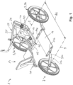
- eine räumliche Darstellung des erfindungsgemäßen Dreirads in einer ersten Sitzposition;
- Figur 2a:
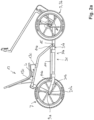
- eine Seitenansicht des in
Figur 1 gezeigten erfindungsgemäßen Dreirads; - Figur 2b:
- eine Seitenansicht von der zu
Figur 2a gegenüberliegenden Seite; - Figur 3:
- eine Draufsicht auf das erfindungsgemäße Dreirad gemäß den
Figuren 1 bis 2b ; - Figur 4a:
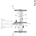
- eine rückwärtige Ansicht des erfindungsgemäßen Dreirads;
- Figur 4b:
- eine frontseitige Ansicht des erfindungsgemäßen Dreirads;
- Figur 5a:
- eine schematische Darstellung der dreieckförmigen Rahmenkonstruktionen zur Erweiterung einer Sitzhöhen-Verstellung, und zwar bei Einstellung der maximalen Sitzhöhe;
- Figur 5b:
- eine entsprechende Darstellung zu
Figur 5a in abgesenkter Sitzposition, bei der die untere Basis des Dreieckes verlängert ist, und zwar unter gleichzeitiger Absenkung der Sitzhöhe; - Figur 6:
- eine weitere räumliche Darstellung des erfindungsgemäßen Dreirads in einer zu den
Figuren 1 bis 4b abweichenden zweiten Sitzposition; - Figur 7a:
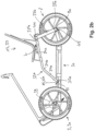
- eine Seitenansicht des in
Figur 5 gezeigten erfindungsgemäßen Dreirads in der zweiten Sitzposition; - Figur 7b:
- eine entsprechende Darstellung zu Figur 6a, jedoch von der gegenüberliegenden Seite;
- Figur 8:
- eine Draufsicht auf das erfindungsgemäße Dreirad in der zweiten Sitzposition;
- Figur 9a:
- eine Frontansicht des in
Figur 5 gezeigten erfindungsgemäßen Dreirads in der zweiten Sitzposition; und - Figur 9b:
- eine rückwärtige Ansicht des erfindungsgemäßen Dreirads in der zweiten Sitzposition.
- Figure 1:
- a spatial representation of the tricycle according to the invention in a first sitting position;
- Figure 2a:
- a side view of the in
Figure 1 shown tricycle according to the invention; - Figure 2b:
- a side view from the to
Figure 2a opposite side; - Figure 3:
- a top view of the tricycle according to the invention according to
Figures 1 to 2b ; - Figure 4a:
- a rear view of the tricycle according to the invention;
- Figure 4b:
- a front view of the tricycle according to the invention;
- Figure 5a:
- a schematic representation of the triangular frame constructions for expanding a seat height adjustment, namely when setting the maximum seat height;
- Figure 5b:
- a corresponding representation
Figure 5a in a lowered sitting position, in which the lower Base of the triangle is extended, while simultaneously lowering the seat height; - Figure 6:
- a further spatial representation of the tricycle according to the invention in one
Figures 1 to 4b different second seating position; - Figure 7a:
- a side view of the in
Figure 5 shown tricycle according to the invention in the second sitting position; - Figure 7b:
- a corresponding representation to Figure 6a, but from the opposite side;
- Figure 8:
- a top view of the tricycle according to the invention in the second sitting position;
- Figure 9a:
- a front view of the in
Figure 5 shown tricycle according to the invention in the second sitting position; and - Figure 9b:
- a rear view of the tricycle according to the invention in the second sitting position.
In
Dieses Dreirad 1 umfasst zwei Vorderräder 3, nämlich ein linkes Vorderrad 3a und ein rechts Vorderrad 3b. Diese drehen um eine gedachte Achslinie 5.This tricycle 1 includes two front wheels 3, namely a left front wheel 3a and a right
Ferner umfasst das Dreirad ein rückwärtiges Rad 7, welches nachfolgend auch kurz als Hinterrad 7 bezeichnet wird, welches um eine gedachte Achslinie 9 dreht.Furthermore, the tricycle includes a
Anstelle des einzelnen Hinterrades 7 kann grundsätzlich auch ein Hinterradpaar mit zwei in unmittelbarer Nähe nebeneinandersitzenden und um eine gemeinsame Drehachse drehende Hinterräder vorgesehen sein (nach Art eines Zwillings-Rades oder Radpaares), die aufgrund ihres geringen Abstands gegenüber dem Abstand zwischen den beiden Vorderrädern 3, d.h. 3a, 3b quasi wie ein einzelnes oder ein gemeinsames Rad wirken. Dieser Aufbau mit zwei Hinterrädern ist jedoch nicht erfindungsgemäß.Instead of the single
Durch den Abstand zwischen der vorderen Achslinie 5 und der hinteren Achslinie 9 wird der Achsabstand AA des Dreirads gebildet.The distance between the front axle line 5 and the
Das Dreirad umfasst einen Rahmen 11, über den letztlich das jeweilige Vorderrad 3a bzw. 3b und auch das Hinterrad 7 gehalten sind, und zwar über die Lager derart, dass die Räder möglichst reibungsarm rotieren können.The tricycle comprises a frame 11, via which the respective
Wie insbesondere aus der Draufsicht gemäß
Durch das Hinterrad 7 ist eine vertikale Mittellängsebene M7 definiert.A vertical central longitudinal plane M7 is defined by the
Durch diese grundsätzliche ein bestimmtes Prinzip wiederspiegelnde Konstruktion ergeben sich wesentliche erfindungsgemäße Vorteile. Denn wie aus den diversen Darstellungen gemäß der
Im gezeigten Ausführungsbeispiel ist dazu ein Boden, eine Bodenfläche, oder ein Bodenbereich oder Lastenboden 14 oder dergleichen vorgesehen, der beispielsweise über eine vorlaufende Verankerungsstelle 114a und eine nachlaufende Befestigungsstelle 114b (siehe
Gemäß der Draufsicht nach
Schließlich wird auf die Mittellängsebene MLE verwiesen, die mittig durch das Dreirad hindurch verläuft, das heißt mit Vertikalausrichtung in der Mitte zwischen dem Radabstand der beiden Vorderräder 3, also der beiden Vorderräder 3a und 3b. Diese vertikale Mittellängsebene MLE ist in
Wie aus der Darstellung gemäß
Aus den Zeichnungen ist auch der weitere Aufbau des Rahmens 11 zu ersehen, der nachfolgend teilweise auch als Rahmenkonstruktion oder Chassis 11 bezeichnet wird.The drawings also show the further structure of the frame 11, which is also sometimes referred to below as the frame structure or chassis 11.
Obgleich dieser Rahmen 11 sehr unterschiedlich umgesetzt werden kann, ist bei dem Rahmen des erfindungsgemäßen Dreirads bevorzugt vorgesehen, dass er als zentrales Element einen Querträger 15 umfasst, an dessen gegenüberliegenden Seitenenden 15a jeweils mit überwiegend nach vorne gerichteter Komponente (also in Längsrichtung) leicht nach außen divergierend verlaufende Frontträger 17 vorgesehen sind, die zu sogenannten Radträgern 19 führen. Die beiden Radträger 19, von denen der eine dem linken und der andere dem rechten Rad 3a, 3b zugeordnet ist, und die dabei jeweils auf der Innenseite des zugeordneten Rades angeordnet sind, sind jeweils gemeinsam um eine bevorzugt vertikale Lenkachse 21 bei der Darstellung gemäß
Die beiden Radträger 19 sind dabei bevorzugt an einem vorlaufenden Ende oder dem vorlaufenden Ende näherliegend über eine quer zur Mittellängsebene MLE verlaufenden Koppelstange 23 miteinander verbunden.The two
Dadurch wird es letztlich ermöglicht, dass durch Verdrehung des Lenkers 25 nach links oder rechts die entsprechende Drehbewegung eines mit dem Lenker 25 drehfest verbundenen Lenkerrohrs 27 über eine nicht näher gezeigte Triebverbindung eine Lenkerhebelverbindungstange 29 entweder nach links oder nach rechts überwiegend längsverschieblich verstellt wird. Da diese Lenkerhebelverbindungsstange 29 an ihrem außenliegenden Ende bei der Draufsicht gemäß
Aus den Zeichnungen ist letztlich auch ersichtlich, dass von dem erwähnten Querträger 15 ein zur Hinterradachse 9 führender Lastenträger 31 (nachfolgend auch Lastenholm 31 genannt) vorgesehen und an seinen gegenüberliegenden Enden entsprechend verankert bzw. abgestützt ist.Ultimately, it can also be seen from the drawings that a load carrier 31 (hereinafter also called load bar 31) leading to the
Der erwähnte Lastenträger 31 ist an seinem vorlaufenden Ende 31'a an dem Querträger oder Querholm 15 fest verankert. Er ist dort um die Längsrichtung des Querholms 15 nicht verschwenkbar. Das nachlaufende Ende 31'b des Lastenträgers 31 ist an der Hinterradachse 9a verankert und darüber gehalten. Dabei verläuft ein vorlaufender Abschnitt des Lastenträgers 31 in horizontaler Ausrichtung bevorzugt in gleicher Höhe, in der auch der Querträger oder Querholm 15 positioniert ist. Über die in Längsrichtung und damit parallel zur Mittellängsebene MLE verlaufende Ausrichtung des Lastenträgers 31 kann dann auch beispielsweise die Tragkonstruktion für Lasten in dem Stauraum SR abgestützt werden, beispielsweise in Form des erwähnten Lastbodens, der Lastfläche oder des Lastbereiches 14.The
Wie aus den Zeichnungen zu ersehen ist, ist der Lastenträger 31 in einen vorlaufenden Lastenträgerabstand 31a und in einen nachlaufenden Lastenträgerabschnitt 31b gegliedert. Der erwähnte vorlaufende Lastenträgerabschnitt 31a geht dabei in einen nachlaufenden Lastenträgerabschnitt 31b über, der letztlich einen Krümmungsabschnitt 31c umfasst, um den sich ein in Richtung Hinterradachse verlaufender Winkelabschnitt 31d anschließt. Der erwähnte Winkelabschnitt 31d verläuft dabei nicht winklig in Richtung Hinterradachse 9a, sondern ist auch noch mit einer leicht ansteigenden Komponente versehen, da sein nachlaufendes Ende 31'b in Höhe der Hinterradachse 9 verankert ist, und diese Verankerungsstelle höher liegt als der vorlaufende Lastenträgerabschnitt 31a.As can be seen from the drawings, the
Da der Lastenträger 31 unterhalb der Lastfläche 14 im Wesentlichen parallel zur Mittellängsebene verläuft, allerdings außermittig zu der zu den Stauraum SR mittig verlaufenden Mittelstauraumebene MSR, sind bevorzugt an dem Lastenträger 31 noch quer vorstehende Lastenträger-Winkel 141 angebracht, beispielsweise angeschweißt, um die Lagerfläche oder den Lastenboden 14 optimal abzustützen.Since the
Insbesondere gemäß der Draufsicht nach
Diese Sitzträgeranordnung 33 umfasst ausgehend vom Querträger 15 - wenn man von der Terminologie eines Fahrradrahmens ausgeht - ein Oberrohr 33a, welches an seinem vorlaufenden Ende 33'a an dem erwähnten Querträger 15 an der Abstützstelle 35a abgestützt ist und welches an seinem nachlaufenden Ende 33"a in ein Hinterrohr 33b übergeht, welches dann wiederum wie erwähnt an der Hinterradachse 9a abgestützt ist.This
Im gezeigten Ausführungsbeispiel verläuft dabei vom vorlaufenden Ende 33'a ausgehend das Oberrohr 33a zunächst in einem ersten Oberrohrabschnitt 34a mit stärkerer Vertikalkomponente, um dann an einem Übergangsbereich 34b in einen zweiten Oberrohrabschnitt 34c überzugehen, dessen Ausrichtung in Seitendarstellung derart ist, dass dessen Horizontal- oder Längserstreckung deutlich größer ist als die Vertikalerstreckung und somit auch der Vertikalanstieg zu seinem rücklaufenden Ende 33"a geringer ausfälltIn the exemplary embodiment shown, starting from the leading end 33'a, the
Grundsätzlich könnte diese so gebildete Sitzträgeranordnung 33 am vor- und am nachlaufenden Ende sowie am Übergang vom Oberrohr 33a zum Hinterrohr 33b starr ausgebildet sein.In principle, this
Auch in einem derartigen Fall könnte beispielsweise der Sitz 13 auf dem Oberrohr 33a, d.h. im gezeigten Ausführungsbeispiel zumindest im zweiten Oberrohrabschnitt 34c in Längsrichtung L verstellt werden, wie dies mittels der Pfeildarstellung L in
Im gezeigten Ausführungsbeispiel ist jedoch das vorlaufende Ende 33'a des Oberrohrs 33a an dem Querträger 15 mittels eines dort vorgesehenen ersten Gelenkes 43 zumindest in einem ausreichenden nachfolgend erörterten Winkelbereich um eine längs zum Querträger 15 verlaufend und damit parallel zur Achslinie 5 oder 9 ausgerichteten Verschwenkachse verschwenkbar. Ferner ist das nachlaufende Ende 33"a des Oberrohrs 33a über ein zweites Gelenk 44 mit dem einen Ende des Hinterrohrs 33b verbunden, welches wiederum über ein drittes Gelenk 45 zumindest mittelbar mit der die Sitzträgeranordnung 33 tragenden Hinterradachse 9a verbindet.In the exemplary embodiment shown, however, the leading end 33'a of the
Durch diese Anordnung ergibt sich grundsätzlich eine MehrPunkt-Anordnung, im gezeigten Ausführungsbeispiel eine Dreiecksanordnung mit drei Gelenkstellen, wodurch in Seitenansicht gemäß
Gemäß der Darstellung nach
Im Rahmen des erfindungsgemäßen Dreirads ist nämlich vorgesehen, dass das durch die Verbindungslinie L31 vereinfacht dargestellte Lastenträger 31, welches auch als Unterrohr 31 bezeichnet wird, eine Einrichtung aufweist, um in seiner Länge verändert werden zu können.In the context of the tricycle according to the invention it is intended that this is simplified by the connecting line
Abstrakt gesprochen kann dieser Lastenträger 31 bzw. das Unterrohr 31 in seiner Länge beispielsweise von der minimalen Längserstreckung gemäß
Da eine derartige Rahmenveränderung beispielsweise von Figur 2a hin zu
Diese Rahmenverstellung ist anhand der nachfolgenden Figuren 6ff näher dargestellt.This frame adjustment is shown in more detail using the following figures 6ff.
Aus den Seitendarstellungen gemäß
Da in dieser Unterrohrkonstruktion gleichzeitig auch die den Stauraum bildende Stauraumkonstruktion verankert ist, beispielsweise in Form eines Stütz- oder Lastbodens, ist dieser Stütz- oder Lastboden 14 an seinem vorlaufenden Ende beispielsweise an einem Abschnitt des nachlaufenden Unterrohrabschnitts 131a an einer Abstützstelle 47 und sein nachlaufendes Ende an einer weiteren Abstützstelle 48 an dem teleskopierbaren weiteren Unterrohrabschnitts 133b abgestützt ist, dazu allerdings längsverschieblich und nicht fest.Since the storage space construction forming the storage space is also anchored in this down tube construction, for example in the form of a support or load floor, this support or load
Dadurch kann die Rahmenkonstruktion beispielsweise von der in
Die beiden ineinander teleskopierbaren Unterrohrabschnitte 133a, 133b können mittels einer in den Zeichnungen nur abstrakt wiedergegebenen Fixiereinrichtung 49 unverschieblich zueinander fixiert werden, um die jeweilige gewünschte Sitzposition zu fixieren.The two telescopic lower tube sections 133a, 133b can be fixed to one another in a non-displaceable manner by means of a fixing
Die Verstellung zwischen einer angehobenen Sitzposition und einer abgesenkten Sitzposition ist so durchführbar, dass beispielsweise eine Verstellung nur zwischen diesen beiden Extremstellungen möglich ist. Es kann aber auch vorgesehen sein, dass dazwischen noch ein oder mehrere Zwischenpositionen eingestellt werden können. Dabei ist vorzugsweise für die Sitzträgeranordnung mit den gelenkig miteinander verbundenen Rohrabschnitten noch eine Fixiereinrichtung vorgesehen. Eine dieser Fixiereinrichtungen kann beispielsweise im Bereich des Gelenks 44 zwischen dem Oberrohr 33a und dem Hinterrohr 33b vorgesehen sein. Eine weitere Fixiereinrichtung ist im Bereich des Gelenks 45 vorgesehen, nämlich am nachlaufenden Ende des Hinterrohrs 33b gegenüber dem Gelenk 45 am Hinterrad 7. Diese Fixiereinrichtungen können formschlüssig ausgebildet sein und dabei z.B. Anschlagsbegrenzungen insbesondere für die abgesenkte Sitzposition aufweisen, so dass ein weiteres Absenken über diese formschlüssige oder anschlagsbedingte Endposition nicht möglich ist. Die erwähnte Fixiereinrichtung 49 für die teleskopierbaren Unterrohrabschnitte 133a und 133b können ebenfalls formschlüssig ausgebildet sein. Alle diese erwähnten bevorzugt formschlüssig ausgebildeten Fixiereinrichtungen können genauso aber auch kraftschlüssig oder form- und kraftschlüssig ausgebildet und realisiert sein. Dazu gleichwirkende Arretier- und Fixiereinrichtungen sind möglich und denkbar, um insbesondere die Sitzposition in der gewünschten Lage zu halten und die hierüber in den Rahmen eingeleiteten Kräfte aufzunehmen und abzustützen.The adjustment between a raised sitting position and a lowered sitting position can be carried out in such a way that, for example, an adjustment is only possible between these two extreme positions. However, it can also be provided that one or more intermediate positions can be set in between. A fixing device is preferably provided for the seat support arrangement with the pipe sections connected to one another in an articulated manner. One of these fixing devices can be provided, for example, in the area of the joint 44 between the
Dabei wird angemerkt, dass jede Längsverstellung des Rahmens 11 und damit jede gewünschte Sitzposition eingestellt und in dieser Position fixiert werden kann, die zwischen der maximalen Längserstreckung und der minimalen Längserstreckung der teleskopierbaren Unterrohrabschnitte 133a, 133b möglich ist dabei kann die Fixierung gegebenenfalls kontinuierlich an beliebiger Stelle zwischen den beiden teleskopierbaren oder teleskopähnlich verstellbaren Unterrohrabschnitten 133a und 133b vorgenommen werden, gegebenenfalls aber auch derart, dass diese beiden zusammenwirkenden Unterrohrabschnitte nur in bestimmten diskreten Schritten fest aneinander fixierbar sind.It should be noted that any longitudinal adjustment of the frame 11 and thus any desired seating position can be set and fixed in this position, which is possible between the maximum longitudinal extent and the minimum longitudinal extent of the telescopic down tube sections 133a, 133b. The fixation can optionally be continuous at any point between the two telescopic or telescopically adjustable down tube sections 133a and 133b, but if necessary also in such a way that these two interacting down tube sections can only be firmly fixed to one another in certain discrete steps.
Entsprechend dieser Längenänderung der Unterrohrabschnitte 133a und 133b wird also nicht nur der Achsabstand AA vergrößert oder verringert, sondern in Abhängigkeit davon auch die Sitzhöhe angehoben oder abgesenkt, da entsprechendes durch die Stellung der beiden Unterrohrabschnitte 133a und 133b vorgegebener Achsabstand dann letztlich die Winkeleinstellung zwischen dem Oberrohr 30a und dem Hinterrohr 33b ändert und damit die Sitzhöhe zwangsweise mit einer entsprechenden Lageveränderung durchführt.According to this change in length of the down tube sections 133a and 133b, not only the center distance AA is increased or reduced, but depending on it The seat height is also raised or lowered, since the corresponding center distance specified by the position of the two down tube sections 133a and 133b then ultimately changes the angle setting between the top tube 30a and the
Damit eine derartige Achsabstandsänderung verbunden mit einer Absenkung oder Anhebung der Sitzposition optimal durchgeführt werden kann, ist die Gesamtanordnung - wie sich schon ergeben hat - in Draufsicht derart gestaltet, dass die Längenverstelleinrichtung für den Lastenträger 31 parallel zur Mittellängsebene MLE verläuft und auch das Oberrohr 33a und das Hinterrohr 33b in Draufsicht parallel zur Mittellängsebene MLE angeordnet sind, sodass die erwähnten Gelenkachsen 43, 44, 45 jeweils senkrecht zur Mittellängsebene ausgerichtet sind. Dadurch gibt es zwei Verbindungseinrichtungen zwischen dem Querträger 15 und der rückwärtigen Hinterradachse 9a, die in ihrem Verstellbereich parallel zur Mittellängsebene verlaufen.So that such a change in the center distance combined with a lowering or raising of the sitting position can be carried out optimally, the overall arrangement - as has already been shown - is designed in plan view in such a way that the length adjustment device for the
Dabei ist das Hinterrad 7 derart angeordnet zu liegen, dass die Sitzträgeranordnung 33 mit Ober- und Hinterrohr 33a, 33b auf der einen Seite des Hinterrades an der zugehörigen Hinterradachse 9a abgestützt ist, wohingegen der Lastenträger 31, der vorzugsweise zumindest mit einem Längsverstellbereich auf der anderen Seite zur Mittellängsebene MLE verläuft, an der gegenüberliegenden Seite des Rades an der Hinterradachse 9a abgestützt ist. Wie bereits erwähnt wurde, ist eine nicht näher gezeigte Verstell- und Fixiereinrichtung im Bereich der vorderen Abstützung des Lenkstangengehäuses vorgesehen, sodass in Abhängigkeit der Sitzposition die Höhe des Lenkers mit verstellt und in der optimalen Höhe fixiert werden kann. Auch in abgesenkter Position beispielsweise gemäß der Darstellung nach
Claims (14)
- Tricycle, with the following features:- with two jointly steerable front wheels (3; 3a, 3b) which are positioned symmetrically to a vertical central longitudinal plane (CLP) running through the tricycle and can be rotated about a common front wheel axle line (5),- with a back wheel (7) that is rotatable around a back wheel axle line (9),- with a seat (13),- that also a height adjustment device is provided for the seat (13),- the height adjustment device (13) comprises a length adjustment device, by means of which the axle distance between the common axle lines running through the front wheels (3; 3a, 3b) when driving straight ahead and the axle line (9) running through the preferably non-steerable rear wheel (7) can be varied in size and can be fixed in the respective axle distance position, characterised in thatthe one rear wheel is positioned off-centre to the central longitudinal plane (CLP) and asymmetrically and the seat is positioned off-centre and therefore asymmetrical to the central longitudinal plane or is arranged at least 75% off-centre, lying on the same side with respect to the central longitudinal plane (CLP) on which the rear wheel is also positioned off-centre.
- Tricycle according to claim 1, characterised in that the tricycle framework (11) has a seat support system (33) which comprises a top tube (33a), which is supported via a rear tube (33b) on the tricycle framework (11), preferably in the form of a crossbeam (15) at least indirectly supporting the front wheels (3), and/or on the rear wheel axle (9a).
- Tricycle according to claim 2, characterised in that the top tube (33a) is supported in the leading area on the crossbeam (15) and/or on both front wheel axles (5a) of both front wheels (3) at least indirectly.
- Tricycle according to claim 2 or 3, characterised in that the top tube (33a) is supported at least indirectly on the down tube or load carrier (31) forming a part of the tricycle framework (11), preferably via the crossbeam (15), and in that the support of the top tube (33a) is supported at least indirectly on the down tube (31) by means of a first joint (43a) and the support of the rear tube (33b) is supported on the down tube (31), the remaining part of the tricycle framework (11) and/or on the rear wheel axle (9a) via a second joint mechanism (34b), wherein it is formed on the connection point between the top tube (33a) and the rear tube (33b) by a third joint connection (45a).
- Tricycle according to claim 4, characterised in that the down tube (31) is equipped with a length adjustment device, whereby the distance between the leading joint (43) and the following joint (45) is changeable in its length and is fixable in the predefined length, whereby the height of the seat (13) is changeable.
- Tricycle according to claim 4 or 5, characterised in that the down tube (31) is adjustable in terms of length and fixable telescopically into and out of itself.
- Tricycle according to claim 6, characterised in that the down tube (31) or the load carrier (31) has a leading down tube section (131a) and a following down tube section (131b),wherein the leading down tube section (131a) is supported at least indirectly via the front wheel axles (3') and the following down tube section (131b) is supported on its following end at least indirectly on the rear wheel axle (9'), wherein the loading base (14) is supported at least by two fixing devices (114a, 114b) on the one hand on the leading down tube section (113a) and on the other hand via the following down tube section (113b),and wherein one of the two fixing devices (114a or 114b) is fixedly supported on one down tube section (113a or 113b) and the other fixing device (114a or 114b) is supported on the respective other down tube section (131b or 131a) displaceable relative thereto.
- Tricycle according to one of the claims 1 to 7, with the following additional features:- with a storage space (SS), and- the storage space (SS) is provided or mainly provided on the side opposite the seat (13) and the rear wheel (7) with respect to the central longitudinal plane (CLP).
- Tricycle according to one of the claims 1 to 8, characterised in that the preferably non-steerable rear wheel (7) is positioned off-centre on the tricycle framework (11) with lateral offset with respect to the central longitudinal plane (CLP).
- Tricycle according to one of the claims 1 to 9, characterised in that the seat (13) is positioned at least 80%, 85%, 95% or at least 95% or up to 100% on the side of the central longitudinal plane (CLP), on which the rear wheel (7) installed off-centre is also located.
- Tricycle according to one of the claims 8 to 10, characterised in that the storage space (SS) is positioned at least 80%, particularly at least 85%, 90%, 95% or to 100% on the side of the central longitudinal plane (CLP) which lies across from the other side in which the rear wheel (7) is located.
- Tricycle according to one of the claims 8 to 11, characterised in that the storage space (SS) has devices for storing and/or for hanging goods to be transported.
- Tricycle according to one of the claims 8 to 12, characterised in that the storage space (SS) at least has a loading base (31) which is preferably plate-shaped, plank-shaped and/or lattice-shaped or box-shaped.
- Tricycle according to one of the claims 1 to 13, characterised in that the seat (13) is attached to a bicycle framework on which it is adjustable and lockable by means of an adjustment device in a longitudinal direction.
Applications Claiming Priority (2)
| Application Number | Priority Date | Filing Date | Title |
|---|---|---|---|
| DE102019135265.7A DE102019135265B4 (en) | 2019-12-19 | 2019-12-19 | tricycle |
| PCT/EP2020/082760 WO2021121851A1 (en) | 2019-12-19 | 2020-11-19 | Tricycle |
Publications (3)
| Publication Number | Publication Date |
|---|---|
| EP4077112A1 EP4077112A1 (en) | 2022-10-26 |
| EP4077112C0 EP4077112C0 (en) | 2023-12-20 |
| EP4077112B1 true EP4077112B1 (en) | 2023-12-20 |
Family
ID=73497790
Family Applications (1)
| Application Number | Title | Priority Date | Filing Date |
|---|---|---|---|
| EP20810959.5A Active EP4077112B1 (en) | 2019-12-19 | 2020-11-19 | Tricycle |
Country Status (3)
| Country | Link |
|---|---|
| EP (1) | EP4077112B1 (en) |
| DE (1) | DE102019135265B4 (en) |
| WO (1) | WO2021121851A1 (en) |
Family Cites Families (7)
| Publication number | Priority date | Publication date | Assignee | Title |
|---|---|---|---|---|
| US1446682A (en) * | 1920-03-29 | 1923-02-27 | Judson Post | Wagon |
| FR823558A (en) * | 1937-05-25 | 1938-01-22 | Frame block with three wheels allowing the mechanical traction of the rickshaws | |
| GB664012A (en) * | 1949-09-20 | 1951-01-02 | Jack Geoffrey Fowler | Improvements in or relating to pedal tricycles |
| CN101698420A (en) * | 2009-09-18 | 2010-04-28 | 郝明刚 | Triangular intelligently-deformed motor vehicle |
| US8540045B2 (en) * | 2011-10-31 | 2013-09-24 | Tanom Motors, LLC | Systems and apparatus for a three-wheeled vehicle |
| CN203142891U (en) * | 2013-01-05 | 2013-08-21 | 高尚义 | Tricycle |
| US8840131B1 (en) * | 2013-03-15 | 2014-09-23 | Planet Rider LLC | Three-wheeled vehicle |
-
2019
- 2019-12-19 DE DE102019135265.7A patent/DE102019135265B4/en active Active
-
2020
- 2020-11-19 WO PCT/EP2020/082760 patent/WO2021121851A1/en unknown
- 2020-11-19 EP EP20810959.5A patent/EP4077112B1/en active Active
Also Published As
| Publication number | Publication date |
|---|---|
| EP4077112C0 (en) | 2023-12-20 |
| WO2021121851A1 (en) | 2021-06-24 |
| DE102019135265A1 (en) | 2021-06-24 |
| EP4077112A1 (en) | 2022-10-26 |
| DE102019135265B4 (en) | 2021-12-02 |
Similar Documents
| Publication | Publication Date | Title |
|---|---|---|
| DE102011106561B4 (en) | Load and / or transport roller | |
| EP2768722B1 (en) | Compact, collapsible bicycle | |
| EP1993899B1 (en) | Vehicle which can tilt in bends, in particular three-wheeled vehicle | |
| DE102019002456B4 (en) | Rear suspension for a bicycle | |
| AT513539B1 (en) | Vehicle with adjustable wheel axle | |
| DE2707562A1 (en) | PLATFORM-STABILIZED, TURNING MOTOR VEHICLE | |
| DE102013108112B4 (en) | Foldable transport wheel | |
| DD154090A5 (en) | velocipede | |
| DE102019003129B3 (en) | THREE-WHEEL ELECTRIC VEHICLE ACCORDING TO EC VEHICLE CLASS L2e-U | |
| EP4077112B1 (en) | Tricycle | |
| EP1996448B1 (en) | Scooter with at least one tread surface unit which can be unfolded laterally | |
| EP0763460B1 (en) | Transport bicycle with front luggage carrier | |
| DE10204311C2 (en) | Bicycle with storage container | |
| EP0892733B1 (en) | Frame structure for a double-axle bicycle for several occupants | |
| EP3819200B1 (en) | Semi-recumbent | |
| DE102006062678B4 (en) | Curved tricycle | |
| DE202017103729U1 (en) | Passenger, freight and transport scooters | |
| WO2013030225A2 (en) | Supporting wheel assembly for a bicycle | |
| DE102011054270A1 (en) | Balance bicycle has steerable front wheels and seat space for placing legs of repulsive locomotive driver, which is located on both sides at underneath of seat | |
| DE102006039457B4 (en) | Multilane vehicle | |
| DE202021101811U1 (en) | Vehicle frame for a four-wheeled vehicle and vehicle that can be operated with muscle power | |
| DE10220241C1 (en) | Folding bicycle has pivot linkage attached to pedal housing allowing folding of bicycle about vertical axis | |
| DE19953897A1 (en) | Device for towing a bicycle | |
| WO2024017937A1 (en) | Single-track vehicle | |
| DE102013012390A1 (en) | Bicycle frame includes seat stays that are provided on each side of the linkage and forms a concentric pivot between the linkage, one seat stay and one extension arm |
Legal Events
| Date | Code | Title | Description |
|---|---|---|---|
| STAA | Information on the status of an ep patent application or granted ep patent |
Free format text: STATUS: UNKNOWN |
|
| STAA | Information on the status of an ep patent application or granted ep patent |
Free format text: STATUS: THE INTERNATIONAL PUBLICATION HAS BEEN MADE |
|
| PUAI | Public reference made under article 153(3) epc to a published international application that has entered the european phase |
Free format text: ORIGINAL CODE: 0009012 |
|
| STAA | Information on the status of an ep patent application or granted ep patent |
Free format text: STATUS: REQUEST FOR EXAMINATION WAS MADE |
|
| 17P | Request for examination filed |
Effective date: 20220317 |
|
| AK | Designated contracting states |
Kind code of ref document: A1 Designated state(s): AL AT BE BG CH CY CZ DE DK EE ES FI FR GB GR HR HU IE IS IT LI LT LU LV MC MK MT NL NO PL PT RO RS SE SI SK SM TR |
|
| DAV | Request for validation of the european patent (deleted) | ||
| DAX | Request for extension of the european patent (deleted) | ||
| GRAP | Despatch of communication of intention to grant a patent |
Free format text: ORIGINAL CODE: EPIDOSNIGR1 |
|
| STAA | Information on the status of an ep patent application or granted ep patent |
Free format text: STATUS: GRANT OF PATENT IS INTENDED |
|
| INTG | Intention to grant announced |
Effective date: 20230720 |
|
| GRAS | Grant fee paid |
Free format text: ORIGINAL CODE: EPIDOSNIGR3 |
|
| GRAA | (expected) grant |
Free format text: ORIGINAL CODE: 0009210 |
|
| STAA | Information on the status of an ep patent application or granted ep patent |
Free format text: STATUS: THE PATENT HAS BEEN GRANTED |
|
| AK | Designated contracting states |
Kind code of ref document: B1 Designated state(s): AL AT BE BG CH CY CZ DE DK EE ES FI FR GB GR HR HU IE IS IT LI LT LU LV MC MK MT NL NO PL PT RO RS SE SI SK SM TR |
|
| REG | Reference to a national code |
Ref country code: GB Ref legal event code: FG4D Free format text: NOT ENGLISH |
|
| REG | Reference to a national code |
Ref country code: CH Ref legal event code: EP |
|
| REG | Reference to a national code |
Ref country code: DE Ref legal event code: R096 Ref document number: 502020006472 Country of ref document: DE |
|
| REG | Reference to a national code |
Ref country code: IE Ref legal event code: FG4D Free format text: LANGUAGE OF EP DOCUMENT: GERMAN |
|
| U01 | Request for unitary effect filed |
Effective date: 20240111 |
|
| U07 | Unitary effect registered |
Designated state(s): AT BE BG DE DK EE FI FR IT LT LU LV MT NL PT SE SI Effective date: 20240119 |
|
| PG25 | Lapsed in a contracting state [announced via postgrant information from national office to epo] |
Ref country code: GR Free format text: LAPSE BECAUSE OF FAILURE TO SUBMIT A TRANSLATION OF THE DESCRIPTION OR TO PAY THE FEE WITHIN THE PRESCRIBED TIME-LIMIT Effective date: 20240321 |
|
| PG25 | Lapsed in a contracting state [announced via postgrant information from national office to epo] |
Ref country code: ES Free format text: LAPSE BECAUSE OF FAILURE TO SUBMIT A TRANSLATION OF THE DESCRIPTION OR TO PAY THE FEE WITHIN THE PRESCRIBED TIME-LIMIT Effective date: 20231220 |
|
| PG25 | Lapsed in a contracting state [announced via postgrant information from national office to epo] |
Ref country code: GR Free format text: LAPSE BECAUSE OF FAILURE TO SUBMIT A TRANSLATION OF THE DESCRIPTION OR TO PAY THE FEE WITHIN THE PRESCRIBED TIME-LIMIT Effective date: 20240321 Ref country code: ES Free format text: LAPSE BECAUSE OF FAILURE TO SUBMIT A TRANSLATION OF THE DESCRIPTION OR TO PAY THE FEE WITHIN THE PRESCRIBED TIME-LIMIT Effective date: 20231220 |