EP4077071B1 - Bremsband einer scheibe für eine scheibenbremse - Google Patents
Bremsband einer scheibe für eine scheibenbremse Download PDFInfo
- Publication number
- EP4077071B1 EP4077071B1 EP20829671.5A EP20829671A EP4077071B1 EP 4077071 B1 EP4077071 B1 EP 4077071B1 EP 20829671 A EP20829671 A EP 20829671A EP 4077071 B1 EP4077071 B1 EP 4077071B1
- Authority
- EP
- European Patent Office
- Prior art keywords
- channel
- projection
- braking
- band
- braking band
- Prior art date
- Legal status (The legal status is an assumption and is not a legal conclusion. Google has not performed a legal analysis and makes no representation as to the accuracy of the status listed.)
- Active
Links
Images


Classifications
-
- B—PERFORMING OPERATIONS; TRANSPORTING
- B60—VEHICLES IN GENERAL
- B60T—VEHICLE BRAKE CONTROL SYSTEMS OR PARTS THEREOF; BRAKE CONTROL SYSTEMS OR PARTS THEREOF, IN GENERAL; ARRANGEMENT OF BRAKING ELEMENTS ON VEHICLES IN GENERAL; PORTABLE DEVICES FOR PREVENTING UNWANTED MOVEMENT OF VEHICLES; VEHICLE MODIFICATIONS TO FACILITATE COOLING OF BRAKES
- B60T1/00—Arrangements of braking elements, i.e. of those parts where braking effect occurs specially for vehicles
- B60T1/02—Arrangements of braking elements, i.e. of those parts where braking effect occurs specially for vehicles acting by retarding wheels
- B60T1/06—Arrangements of braking elements, i.e. of those parts where braking effect occurs specially for vehicles acting by retarding wheels acting otherwise than on tread, e.g. employing rim, drum, disc, or transmission or on double wheels
- B60T1/065—Arrangements of braking elements, i.e. of those parts where braking effect occurs specially for vehicles acting by retarding wheels acting otherwise than on tread, e.g. employing rim, drum, disc, or transmission or on double wheels employing disc
-
- B—PERFORMING OPERATIONS; TRANSPORTING
- B32—LAYERED PRODUCTS
- B32B—LAYERED PRODUCTS, i.e. PRODUCTS BUILT-UP OF STRATA OF FLAT OR NON-FLAT, e.g. CELLULAR OR HONEYCOMB, FORM
- B32B15/00—Layered products comprising a layer of metal
- B32B15/01—Layered products comprising a layer of metal all layers being exclusively metallic
- B32B15/011—Layered products comprising a layer of metal all layers being exclusively metallic all layers being formed of iron alloys or steels
-
- C—CHEMISTRY; METALLURGY
- C23—COATING METALLIC MATERIAL; COATING MATERIAL WITH METALLIC MATERIAL; CHEMICAL SURFACE TREATMENT; DIFFUSION TREATMENT OF METALLIC MATERIAL; COATING BY VACUUM EVAPORATION, BY SPUTTERING, BY ION IMPLANTATION OR BY CHEMICAL VAPOUR DEPOSITION, IN GENERAL; INHIBITING CORROSION OF METALLIC MATERIAL OR INCRUSTATION IN GENERAL
- C23C—COATING METALLIC MATERIAL; COATING MATERIAL WITH METALLIC MATERIAL; SURFACE TREATMENT OF METALLIC MATERIAL BY DIFFUSION INTO THE SURFACE, BY CHEMICAL CONVERSION OR SUBSTITUTION; COATING BY VACUUM EVAPORATION, BY SPUTTERING, BY ION IMPLANTATION OR BY CHEMICAL VAPOUR DEPOSITION, IN GENERAL
- C23C24/00—Coating starting from inorganic powder
- C23C24/02—Coating starting from inorganic powder by application of pressure only
- C23C24/04—Impact or kinetic deposition of particles
-
- C—CHEMISTRY; METALLURGY
- C23—COATING METALLIC MATERIAL; COATING MATERIAL WITH METALLIC MATERIAL; CHEMICAL SURFACE TREATMENT; DIFFUSION TREATMENT OF METALLIC MATERIAL; COATING BY VACUUM EVAPORATION, BY SPUTTERING, BY ION IMPLANTATION OR BY CHEMICAL VAPOUR DEPOSITION, IN GENERAL; INHIBITING CORROSION OF METALLIC MATERIAL OR INCRUSTATION IN GENERAL
- C23C—COATING METALLIC MATERIAL; COATING MATERIAL WITH METALLIC MATERIAL; SURFACE TREATMENT OF METALLIC MATERIAL BY DIFFUSION INTO THE SURFACE, BY CHEMICAL CONVERSION OR SUBSTITUTION; COATING BY VACUUM EVAPORATION, BY SPUTTERING, BY ION IMPLANTATION OR BY CHEMICAL VAPOUR DEPOSITION, IN GENERAL
- C23C28/00—Coating for obtaining at least two superposed coatings either by methods not provided for in a single one of groups C23C2/00 - C23C26/00 or by combinations of methods provided for in subclasses C23C and C25C or C25D
- C23C28/30—Coatings combining at least one metallic layer and at least one inorganic non-metallic layer
- C23C28/32—Coatings combining at least one metallic layer and at least one inorganic non-metallic layer including at least one pure metallic layer
- C23C28/322—Coatings combining at least one metallic layer and at least one inorganic non-metallic layer including at least one pure metallic layer only coatings of metal elements only
-
- C—CHEMISTRY; METALLURGY
- C23—COATING METALLIC MATERIAL; COATING MATERIAL WITH METALLIC MATERIAL; CHEMICAL SURFACE TREATMENT; DIFFUSION TREATMENT OF METALLIC MATERIAL; COATING BY VACUUM EVAPORATION, BY SPUTTERING, BY ION IMPLANTATION OR BY CHEMICAL VAPOUR DEPOSITION, IN GENERAL; INHIBITING CORROSION OF METALLIC MATERIAL OR INCRUSTATION IN GENERAL
- C23C—COATING METALLIC MATERIAL; COATING MATERIAL WITH METALLIC MATERIAL; SURFACE TREATMENT OF METALLIC MATERIAL BY DIFFUSION INTO THE SURFACE, BY CHEMICAL CONVERSION OR SUBSTITUTION; COATING BY VACUUM EVAPORATION, BY SPUTTERING, BY ION IMPLANTATION OR BY CHEMICAL VAPOUR DEPOSITION, IN GENERAL
- C23C28/00—Coating for obtaining at least two superposed coatings either by methods not provided for in a single one of groups C23C2/00 - C23C26/00 or by combinations of methods provided for in subclasses C23C and C25C or C25D
- C23C28/30—Coatings combining at least one metallic layer and at least one inorganic non-metallic layer
- C23C28/34—Coatings combining at least one metallic layer and at least one inorganic non-metallic layer including at least one inorganic non-metallic material layer, e.g. metal carbide, nitride, boride, silicide layer and their mixtures, enamels, phosphates and sulphates
- C23C28/341—Coatings combining at least one metallic layer and at least one inorganic non-metallic layer including at least one inorganic non-metallic material layer, e.g. metal carbide, nitride, boride, silicide layer and their mixtures, enamels, phosphates and sulphates with at least one carbide layer
-
- C—CHEMISTRY; METALLURGY
- C23—COATING METALLIC MATERIAL; COATING MATERIAL WITH METALLIC MATERIAL; CHEMICAL SURFACE TREATMENT; DIFFUSION TREATMENT OF METALLIC MATERIAL; COATING BY VACUUM EVAPORATION, BY SPUTTERING, BY ION IMPLANTATION OR BY CHEMICAL VAPOUR DEPOSITION, IN GENERAL; INHIBITING CORROSION OF METALLIC MATERIAL OR INCRUSTATION IN GENERAL
- C23C—COATING METALLIC MATERIAL; COATING MATERIAL WITH METALLIC MATERIAL; SURFACE TREATMENT OF METALLIC MATERIAL BY DIFFUSION INTO THE SURFACE, BY CHEMICAL CONVERSION OR SUBSTITUTION; COATING BY VACUUM EVAPORATION, BY SPUTTERING, BY ION IMPLANTATION OR BY CHEMICAL VAPOUR DEPOSITION, IN GENERAL
- C23C4/00—Coating by spraying the coating material in the molten state, e.g. by flame, plasma or electric discharge
- C23C4/02—Pretreatment of the material to be coated, e.g. for coating on selected surface areas
-
- C—CHEMISTRY; METALLURGY
- C23—COATING METALLIC MATERIAL; COATING MATERIAL WITH METALLIC MATERIAL; CHEMICAL SURFACE TREATMENT; DIFFUSION TREATMENT OF METALLIC MATERIAL; COATING BY VACUUM EVAPORATION, BY SPUTTERING, BY ION IMPLANTATION OR BY CHEMICAL VAPOUR DEPOSITION, IN GENERAL; INHIBITING CORROSION OF METALLIC MATERIAL OR INCRUSTATION IN GENERAL
- C23C—COATING METALLIC MATERIAL; COATING MATERIAL WITH METALLIC MATERIAL; SURFACE TREATMENT OF METALLIC MATERIAL BY DIFFUSION INTO THE SURFACE, BY CHEMICAL CONVERSION OR SUBSTITUTION; COATING BY VACUUM EVAPORATION, BY SPUTTERING, BY ION IMPLANTATION OR BY CHEMICAL VAPOUR DEPOSITION, IN GENERAL
- C23C4/00—Coating by spraying the coating material in the molten state, e.g. by flame, plasma or electric discharge
- C23C4/04—Coating by spraying the coating material in the molten state, e.g. by flame, plasma or electric discharge characterised by the coating material
- C23C4/06—Metallic material
- C23C4/067—Metallic material containing free particles of non-metal elements, e.g. carbon, silicon, boron, phosphorus or arsenic
-
- C—CHEMISTRY; METALLURGY
- C23—COATING METALLIC MATERIAL; COATING MATERIAL WITH METALLIC MATERIAL; CHEMICAL SURFACE TREATMENT; DIFFUSION TREATMENT OF METALLIC MATERIAL; COATING BY VACUUM EVAPORATION, BY SPUTTERING, BY ION IMPLANTATION OR BY CHEMICAL VAPOUR DEPOSITION, IN GENERAL; INHIBITING CORROSION OF METALLIC MATERIAL OR INCRUSTATION IN GENERAL
- C23C—COATING METALLIC MATERIAL; COATING MATERIAL WITH METALLIC MATERIAL; SURFACE TREATMENT OF METALLIC MATERIAL BY DIFFUSION INTO THE SURFACE, BY CHEMICAL CONVERSION OR SUBSTITUTION; COATING BY VACUUM EVAPORATION, BY SPUTTERING, BY ION IMPLANTATION OR BY CHEMICAL VAPOUR DEPOSITION, IN GENERAL
- C23C4/00—Coating by spraying the coating material in the molten state, e.g. by flame, plasma or electric discharge
- C23C4/04—Coating by spraying the coating material in the molten state, e.g. by flame, plasma or electric discharge characterised by the coating material
- C23C4/06—Metallic material
- C23C4/08—Metallic material containing only metal elements
-
- C—CHEMISTRY; METALLURGY
- C23—COATING METALLIC MATERIAL; COATING MATERIAL WITH METALLIC MATERIAL; CHEMICAL SURFACE TREATMENT; DIFFUSION TREATMENT OF METALLIC MATERIAL; COATING BY VACUUM EVAPORATION, BY SPUTTERING, BY ION IMPLANTATION OR BY CHEMICAL VAPOUR DEPOSITION, IN GENERAL; INHIBITING CORROSION OF METALLIC MATERIAL OR INCRUSTATION IN GENERAL
- C23C—COATING METALLIC MATERIAL; COATING MATERIAL WITH METALLIC MATERIAL; SURFACE TREATMENT OF METALLIC MATERIAL BY DIFFUSION INTO THE SURFACE, BY CHEMICAL CONVERSION OR SUBSTITUTION; COATING BY VACUUM EVAPORATION, BY SPUTTERING, BY ION IMPLANTATION OR BY CHEMICAL VAPOUR DEPOSITION, IN GENERAL
- C23C4/00—Coating by spraying the coating material in the molten state, e.g. by flame, plasma or electric discharge
- C23C4/04—Coating by spraying the coating material in the molten state, e.g. by flame, plasma or electric discharge characterised by the coating material
- C23C4/10—Oxides, borides, carbides, nitrides or silicides; Mixtures thereof
-
- C—CHEMISTRY; METALLURGY
- C23—COATING METALLIC MATERIAL; COATING MATERIAL WITH METALLIC MATERIAL; CHEMICAL SURFACE TREATMENT; DIFFUSION TREATMENT OF METALLIC MATERIAL; COATING BY VACUUM EVAPORATION, BY SPUTTERING, BY ION IMPLANTATION OR BY CHEMICAL VAPOUR DEPOSITION, IN GENERAL; INHIBITING CORROSION OF METALLIC MATERIAL OR INCRUSTATION IN GENERAL
- C23C—COATING METALLIC MATERIAL; COATING MATERIAL WITH METALLIC MATERIAL; SURFACE TREATMENT OF METALLIC MATERIAL BY DIFFUSION INTO THE SURFACE, BY CHEMICAL CONVERSION OR SUBSTITUTION; COATING BY VACUUM EVAPORATION, BY SPUTTERING, BY ION IMPLANTATION OR BY CHEMICAL VAPOUR DEPOSITION, IN GENERAL
- C23C4/00—Coating by spraying the coating material in the molten state, e.g. by flame, plasma or electric discharge
- C23C4/12—Coating by spraying the coating material in the molten state, e.g. by flame, plasma or electric discharge characterised by the method of spraying
- C23C4/129—Flame spraying
-
- C—CHEMISTRY; METALLURGY
- C23—COATING METALLIC MATERIAL; COATING MATERIAL WITH METALLIC MATERIAL; CHEMICAL SURFACE TREATMENT; DIFFUSION TREATMENT OF METALLIC MATERIAL; COATING BY VACUUM EVAPORATION, BY SPUTTERING, BY ION IMPLANTATION OR BY CHEMICAL VAPOUR DEPOSITION, IN GENERAL; INHIBITING CORROSION OF METALLIC MATERIAL OR INCRUSTATION IN GENERAL
- C23C—COATING METALLIC MATERIAL; COATING MATERIAL WITH METALLIC MATERIAL; SURFACE TREATMENT OF METALLIC MATERIAL BY DIFFUSION INTO THE SURFACE, BY CHEMICAL CONVERSION OR SUBSTITUTION; COATING BY VACUUM EVAPORATION, BY SPUTTERING, BY ION IMPLANTATION OR BY CHEMICAL VAPOUR DEPOSITION, IN GENERAL
- C23C4/00—Coating by spraying the coating material in the molten state, e.g. by flame, plasma or electric discharge
- C23C4/12—Coating by spraying the coating material in the molten state, e.g. by flame, plasma or electric discharge characterised by the method of spraying
- C23C4/131—Wire arc spraying
-
- C—CHEMISTRY; METALLURGY
- C23—COATING METALLIC MATERIAL; COATING MATERIAL WITH METALLIC MATERIAL; CHEMICAL SURFACE TREATMENT; DIFFUSION TREATMENT OF METALLIC MATERIAL; COATING BY VACUUM EVAPORATION, BY SPUTTERING, BY ION IMPLANTATION OR BY CHEMICAL VAPOUR DEPOSITION, IN GENERAL; INHIBITING CORROSION OF METALLIC MATERIAL OR INCRUSTATION IN GENERAL
- C23C—COATING METALLIC MATERIAL; COATING MATERIAL WITH METALLIC MATERIAL; SURFACE TREATMENT OF METALLIC MATERIAL BY DIFFUSION INTO THE SURFACE, BY CHEMICAL CONVERSION OR SUBSTITUTION; COATING BY VACUUM EVAPORATION, BY SPUTTERING, BY ION IMPLANTATION OR BY CHEMICAL VAPOUR DEPOSITION, IN GENERAL
- C23C8/00—Solid state diffusion of only non-metal elements into metallic material surfaces; Chemical surface treatment of metallic material by reaction of the surface with a reactive gas, leaving reaction products of surface material in the coating, e.g. conversion coatings, passivation of metals
- C23C8/02—Pretreatment of the material to be coated
-
- C—CHEMISTRY; METALLURGY
- C23—COATING METALLIC MATERIAL; COATING MATERIAL WITH METALLIC MATERIAL; CHEMICAL SURFACE TREATMENT; DIFFUSION TREATMENT OF METALLIC MATERIAL; COATING BY VACUUM EVAPORATION, BY SPUTTERING, BY ION IMPLANTATION OR BY CHEMICAL VAPOUR DEPOSITION, IN GENERAL; INHIBITING CORROSION OF METALLIC MATERIAL OR INCRUSTATION IN GENERAL
- C23C—COATING METALLIC MATERIAL; COATING MATERIAL WITH METALLIC MATERIAL; SURFACE TREATMENT OF METALLIC MATERIAL BY DIFFUSION INTO THE SURFACE, BY CHEMICAL CONVERSION OR SUBSTITUTION; COATING BY VACUUM EVAPORATION, BY SPUTTERING, BY ION IMPLANTATION OR BY CHEMICAL VAPOUR DEPOSITION, IN GENERAL
- C23C8/00—Solid state diffusion of only non-metal elements into metallic material surfaces; Chemical surface treatment of metallic material by reaction of the surface with a reactive gas, leaving reaction products of surface material in the coating, e.g. conversion coatings, passivation of metals
- C23C8/06—Solid state diffusion of only non-metal elements into metallic material surfaces; Chemical surface treatment of metallic material by reaction of the surface with a reactive gas, leaving reaction products of surface material in the coating, e.g. conversion coatings, passivation of metals using gases
- C23C8/28—Solid state diffusion of only non-metal elements into metallic material surfaces; Chemical surface treatment of metallic material by reaction of the surface with a reactive gas, leaving reaction products of surface material in the coating, e.g. conversion coatings, passivation of metals using gases more than one element being applied in one step
- C23C8/30—Carbo-nitriding
- C23C8/32—Carbo-nitriding of ferrous surfaces
-
- C—CHEMISTRY; METALLURGY
- C23—COATING METALLIC MATERIAL; COATING MATERIAL WITH METALLIC MATERIAL; CHEMICAL SURFACE TREATMENT; DIFFUSION TREATMENT OF METALLIC MATERIAL; COATING BY VACUUM EVAPORATION, BY SPUTTERING, BY ION IMPLANTATION OR BY CHEMICAL VAPOUR DEPOSITION, IN GENERAL; INHIBITING CORROSION OF METALLIC MATERIAL OR INCRUSTATION IN GENERAL
- C23C—COATING METALLIC MATERIAL; COATING MATERIAL WITH METALLIC MATERIAL; SURFACE TREATMENT OF METALLIC MATERIAL BY DIFFUSION INTO THE SURFACE, BY CHEMICAL CONVERSION OR SUBSTITUTION; COATING BY VACUUM EVAPORATION, BY SPUTTERING, BY ION IMPLANTATION OR BY CHEMICAL VAPOUR DEPOSITION, IN GENERAL
- C23C8/00—Solid state diffusion of only non-metal elements into metallic material surfaces; Chemical surface treatment of metallic material by reaction of the surface with a reactive gas, leaving reaction products of surface material in the coating, e.g. conversion coatings, passivation of metals
- C23C8/40—Solid state diffusion of only non-metal elements into metallic material surfaces; Chemical surface treatment of metallic material by reaction of the surface with a reactive gas, leaving reaction products of surface material in the coating, e.g. conversion coatings, passivation of metals using liquids, e.g. salt baths, liquid suspensions
- C23C8/52—Solid state diffusion of only non-metal elements into metallic material surfaces; Chemical surface treatment of metallic material by reaction of the surface with a reactive gas, leaving reaction products of surface material in the coating, e.g. conversion coatings, passivation of metals using liquids, e.g. salt baths, liquid suspensions more than one element being applied in one step
- C23C8/54—Carbo-nitriding
- C23C8/56—Carbo-nitriding of ferrous surfaces
-
- C—CHEMISTRY; METALLURGY
- C23—COATING METALLIC MATERIAL; COATING MATERIAL WITH METALLIC MATERIAL; CHEMICAL SURFACE TREATMENT; DIFFUSION TREATMENT OF METALLIC MATERIAL; COATING BY VACUUM EVAPORATION, BY SPUTTERING, BY ION IMPLANTATION OR BY CHEMICAL VAPOUR DEPOSITION, IN GENERAL; INHIBITING CORROSION OF METALLIC MATERIAL OR INCRUSTATION IN GENERAL
- C23C—COATING METALLIC MATERIAL; COATING MATERIAL WITH METALLIC MATERIAL; SURFACE TREATMENT OF METALLIC MATERIAL BY DIFFUSION INTO THE SURFACE, BY CHEMICAL CONVERSION OR SUBSTITUTION; COATING BY VACUUM EVAPORATION, BY SPUTTERING, BY ION IMPLANTATION OR BY CHEMICAL VAPOUR DEPOSITION, IN GENERAL
- C23C8/00—Solid state diffusion of only non-metal elements into metallic material surfaces; Chemical surface treatment of metallic material by reaction of the surface with a reactive gas, leaving reaction products of surface material in the coating, e.g. conversion coatings, passivation of metals
- C23C8/60—Solid state diffusion of only non-metal elements into metallic material surfaces; Chemical surface treatment of metallic material by reaction of the surface with a reactive gas, leaving reaction products of surface material in the coating, e.g. conversion coatings, passivation of metals using solids, e.g. powders, pastes
- C23C8/72—Solid state diffusion of only non-metal elements into metallic material surfaces; Chemical surface treatment of metallic material by reaction of the surface with a reactive gas, leaving reaction products of surface material in the coating, e.g. conversion coatings, passivation of metals using solids, e.g. powders, pastes more than one element being applied in one step
- C23C8/74—Carbo-nitriding
- C23C8/76—Carbo-nitriding of ferrous surfaces
-
- C—CHEMISTRY; METALLURGY
- C23—COATING METALLIC MATERIAL; COATING MATERIAL WITH METALLIC MATERIAL; CHEMICAL SURFACE TREATMENT; DIFFUSION TREATMENT OF METALLIC MATERIAL; COATING BY VACUUM EVAPORATION, BY SPUTTERING, BY ION IMPLANTATION OR BY CHEMICAL VAPOUR DEPOSITION, IN GENERAL; INHIBITING CORROSION OF METALLIC MATERIAL OR INCRUSTATION IN GENERAL
- C23C—COATING METALLIC MATERIAL; COATING MATERIAL WITH METALLIC MATERIAL; SURFACE TREATMENT OF METALLIC MATERIAL BY DIFFUSION INTO THE SURFACE, BY CHEMICAL CONVERSION OR SUBSTITUTION; COATING BY VACUUM EVAPORATION, BY SPUTTERING, BY ION IMPLANTATION OR BY CHEMICAL VAPOUR DEPOSITION, IN GENERAL
- C23C8/00—Solid state diffusion of only non-metal elements into metallic material surfaces; Chemical surface treatment of metallic material by reaction of the surface with a reactive gas, leaving reaction products of surface material in the coating, e.g. conversion coatings, passivation of metals
- C23C8/80—After-treatment
-
- F—MECHANICAL ENGINEERING; LIGHTING; HEATING; WEAPONS; BLASTING
- F16—ENGINEERING ELEMENTS AND UNITS; GENERAL MEASURES FOR PRODUCING AND MAINTAINING EFFECTIVE FUNCTIONING OF MACHINES OR INSTALLATIONS; THERMAL INSULATION IN GENERAL
- F16D—COUPLINGS FOR TRANSMITTING ROTATION; CLUTCHES; BRAKES
- F16D65/00—Parts or details
- F16D65/02—Braking members; Mounting thereof
- F16D65/12—Discs; Drums for disc brakes
- F16D65/123—Discs; Drums for disc brakes comprising an annular disc secured to a hub member; Discs characterised by means for mounting
-
- F—MECHANICAL ENGINEERING; LIGHTING; HEATING; WEAPONS; BLASTING
- F16—ENGINEERING ELEMENTS AND UNITS; GENERAL MEASURES FOR PRODUCING AND MAINTAINING EFFECTIVE FUNCTIONING OF MACHINES OR INSTALLATIONS; THERMAL INSULATION IN GENERAL
- F16D—COUPLINGS FOR TRANSMITTING ROTATION; CLUTCHES; BRAKES
- F16D65/00—Parts or details
- F16D65/02—Braking members; Mounting thereof
- F16D65/12—Discs; Drums for disc brakes
- F16D65/125—Discs; Drums for disc brakes characterised by the material used for the disc body
-
- F—MECHANICAL ENGINEERING; LIGHTING; HEATING; WEAPONS; BLASTING
- F16—ENGINEERING ELEMENTS AND UNITS; GENERAL MEASURES FOR PRODUCING AND MAINTAINING EFFECTIVE FUNCTIONING OF MACHINES OR INSTALLATIONS; THERMAL INSULATION IN GENERAL
- F16D—COUPLINGS FOR TRANSMITTING ROTATION; CLUTCHES; BRAKES
- F16D65/00—Parts or details
- F16D65/02—Braking members; Mounting thereof
- F16D65/12—Discs; Drums for disc brakes
- F16D65/127—Discs; Drums for disc brakes characterised by properties of the disc surface; Discs lined with friction material
-
- F—MECHANICAL ENGINEERING; LIGHTING; HEATING; WEAPONS; BLASTING
- F16—ENGINEERING ELEMENTS AND UNITS; GENERAL MEASURES FOR PRODUCING AND MAINTAINING EFFECTIVE FUNCTIONING OF MACHINES OR INSTALLATIONS; THERMAL INSULATION IN GENERAL
- F16D—COUPLINGS FOR TRANSMITTING ROTATION; CLUTCHES; BRAKES
- F16D69/00—Friction linings; Attachment thereof; Selection of coacting friction substances or surfaces
- F16D69/02—Composition of linings ; Methods of manufacturing
- F16D69/027—Compositions based on metals or inorganic oxides
-
- F—MECHANICAL ENGINEERING; LIGHTING; HEATING; WEAPONS; BLASTING
- F16—ENGINEERING ELEMENTS AND UNITS; GENERAL MEASURES FOR PRODUCING AND MAINTAINING EFFECTIVE FUNCTIONING OF MACHINES OR INSTALLATIONS; THERMAL INSULATION IN GENERAL
- F16D—COUPLINGS FOR TRANSMITTING ROTATION; CLUTCHES; BRAKES
- F16D65/00—Parts or details
- F16D65/02—Braking members; Mounting thereof
- F16D2065/13—Parts or details of discs or drums
- F16D2065/1304—Structure
- F16D2065/132—Structure layered
-
- F—MECHANICAL ENGINEERING; LIGHTING; HEATING; WEAPONS; BLASTING
- F16—ENGINEERING ELEMENTS AND UNITS; GENERAL MEASURES FOR PRODUCING AND MAINTAINING EFFECTIVE FUNCTIONING OF MACHINES OR INSTALLATIONS; THERMAL INSULATION IN GENERAL
- F16D—COUPLINGS FOR TRANSMITTING ROTATION; CLUTCHES; BRAKES
- F16D69/00—Friction linings; Attachment thereof; Selection of coacting friction substances or surfaces
- F16D2069/001—Material of friction lining and support element of same or similar composition
-
- F—MECHANICAL ENGINEERING; LIGHTING; HEATING; WEAPONS; BLASTING
- F16—ENGINEERING ELEMENTS AND UNITS; GENERAL MEASURES FOR PRODUCING AND MAINTAINING EFFECTIVE FUNCTIONING OF MACHINES OR INSTALLATIONS; THERMAL INSULATION IN GENERAL
- F16D—COUPLINGS FOR TRANSMITTING ROTATION; CLUTCHES; BRAKES
- F16D69/00—Friction linings; Attachment thereof; Selection of coacting friction substances or surfaces
- F16D2069/003—Selection of coacting friction materials
-
- F—MECHANICAL ENGINEERING; LIGHTING; HEATING; WEAPONS; BLASTING
- F16—ENGINEERING ELEMENTS AND UNITS; GENERAL MEASURES FOR PRODUCING AND MAINTAINING EFFECTIVE FUNCTIONING OF MACHINES OR INSTALLATIONS; THERMAL INSULATION IN GENERAL
- F16D—COUPLINGS FOR TRANSMITTING ROTATION; CLUTCHES; BRAKES
- F16D69/00—Friction linings; Attachment thereof; Selection of coacting friction substances or surfaces
- F16D2069/004—Profiled friction surfaces, e.g. grooves, dimples
-
- F—MECHANICAL ENGINEERING; LIGHTING; HEATING; WEAPONS; BLASTING
- F16—ENGINEERING ELEMENTS AND UNITS; GENERAL MEASURES FOR PRODUCING AND MAINTAINING EFFECTIVE FUNCTIONING OF MACHINES OR INSTALLATIONS; THERMAL INSULATION IN GENERAL
- F16D—COUPLINGS FOR TRANSMITTING ROTATION; CLUTCHES; BRAKES
- F16D69/00—Friction linings; Attachment thereof; Selection of coacting friction substances or surfaces
- F16D69/04—Attachment of linings
- F16D2069/0425—Attachment methods or devices
- F16D2069/0483—Lining or lining carrier material shaped in situ
-
- F—MECHANICAL ENGINEERING; LIGHTING; HEATING; WEAPONS; BLASTING
- F16—ENGINEERING ELEMENTS AND UNITS; GENERAL MEASURES FOR PRODUCING AND MAINTAINING EFFECTIVE FUNCTIONING OF MACHINES OR INSTALLATIONS; THERMAL INSULATION IN GENERAL
- F16D—COUPLINGS FOR TRANSMITTING ROTATION; CLUTCHES; BRAKES
- F16D69/00—Friction linings; Attachment thereof; Selection of coacting friction substances or surfaces
- F16D69/04—Attachment of linings
- F16D2069/0425—Attachment methods or devices
- F16D2069/0491—Tools, machines, processes
-
- F—MECHANICAL ENGINEERING; LIGHTING; HEATING; WEAPONS; BLASTING
- F16—ENGINEERING ELEMENTS AND UNITS; GENERAL MEASURES FOR PRODUCING AND MAINTAINING EFFECTIVE FUNCTIONING OF MACHINES OR INSTALLATIONS; THERMAL INSULATION IN GENERAL
- F16D—COUPLINGS FOR TRANSMITTING ROTATION; CLUTCHES; BRAKES
- F16D2200/00—Materials; Production methods therefor
- F16D2200/0004—Materials; Production methods therefor metallic
- F16D2200/0008—Ferro
-
- F—MECHANICAL ENGINEERING; LIGHTING; HEATING; WEAPONS; BLASTING
- F16—ENGINEERING ELEMENTS AND UNITS; GENERAL MEASURES FOR PRODUCING AND MAINTAINING EFFECTIVE FUNCTIONING OF MACHINES OR INSTALLATIONS; THERMAL INSULATION IN GENERAL
- F16D—COUPLINGS FOR TRANSMITTING ROTATION; CLUTCHES; BRAKES
- F16D2200/00—Materials; Production methods therefor
- F16D2200/0004—Materials; Production methods therefor metallic
- F16D2200/0026—Non-ferro
-
- F—MECHANICAL ENGINEERING; LIGHTING; HEATING; WEAPONS; BLASTING
- F16—ENGINEERING ELEMENTS AND UNITS; GENERAL MEASURES FOR PRODUCING AND MAINTAINING EFFECTIVE FUNCTIONING OF MACHINES OR INSTALLATIONS; THERMAL INSULATION IN GENERAL
- F16D—COUPLINGS FOR TRANSMITTING ROTATION; CLUTCHES; BRAKES
- F16D2200/00—Materials; Production methods therefor
- F16D2200/0078—Materials; Production methods therefor laminated
-
- F—MECHANICAL ENGINEERING; LIGHTING; HEATING; WEAPONS; BLASTING
- F16—ENGINEERING ELEMENTS AND UNITS; GENERAL MEASURES FOR PRODUCING AND MAINTAINING EFFECTIVE FUNCTIONING OF MACHINES OR INSTALLATIONS; THERMAL INSULATION IN GENERAL
- F16D—COUPLINGS FOR TRANSMITTING ROTATION; CLUTCHES; BRAKES
- F16D2250/00—Manufacturing; Assembly
- F16D2250/0038—Surface treatment
- F16D2250/0046—Coating
-
- F—MECHANICAL ENGINEERING; LIGHTING; HEATING; WEAPONS; BLASTING
- F16—ENGINEERING ELEMENTS AND UNITS; GENERAL MEASURES FOR PRODUCING AND MAINTAINING EFFECTIVE FUNCTIONING OF MACHINES OR INSTALLATIONS; THERMAL INSULATION IN GENERAL
- F16D—COUPLINGS FOR TRANSMITTING ROTATION; CLUTCHES; BRAKES
- F16D2250/00—Manufacturing; Assembly
- F16D2250/0092—Tools or machines for producing linings
Definitions
- the present invention relates to a braking band and a disk for disk brake, particularly, but not exclusively, for applications in the automobile field, and a vehicle having said ventilated disk.
- the brake caliper is generally arranged straddling the outer peripheral margin of a brake disk, adapted to rotate about a rotation axis (A-A) defining an axial direction (X-X).
- a radial direction (R-R) is further defined, substantially orthogonal to said axial direction (X-X), and a circumferential direction (C-C), orthogonal to said axial direction (X-X), to said radial direction (R-R) and locally a tangential direction (T-T), or rather accurately, i.e. in intersection points of an axial and radial direction, orthogonal to both said axial direction (X-X) and said radial direction (R-R).
- disks for disk brake comprise a bell adapted to associate the disk with a hub of a vehicle, from which an annular portion, named a braking band, which is intended to cooperate with brake pads of a caliper, extends.
- the braking band is made by means of two plates facing and connected to each other by means of connecting elements, respectively, e.g. in the shape of pins or fins.
- the outer surfaces of the two plates define opposite braking surfaces, while the inner surfaces, together with the pins or fins, delimit ventilation channels for cooling the disk, which channels are crossed by airflows according to a centrifugal direction during the rotary motion of the disk itself.
- Said braking band is intended to cooperate with disk brake calipers adapted to apply a braking action on the vehicle by applying, by means of the aforesaid pads, friction on opposite surfaces of the two plates, named braking surfaces.
- the controlled interaction between the opposing brake pads and the opposite braking surfaces of the braking band determines a braking action by friction which allows the deceleration or stopping of the vehicle.
- the brake disk is made of gray cast iron or steel. Indeed, this material makes it possible to obtain good braking performance (especially in terms of wear containment) at a relatively low cost. Disks made of carbon or carbo-ceramic materials offer much greater performance, but at a much higher cost.
- a protective coating of this type is described, for example, in patent US4715486 , related to a low-wear disk brake.
- the disk made in particular of cast iron, has a coating made of a particle material deposited on the disk by a high kinetic energy impacting technique.
- the coating contains from 20% to 30% of tungsten carbide, 5% of nickel, and the remaining part of a mixture of chromium carbides and tungsten.
- the coating contains from 80% to 90% of tungsten carbide, up to 10% cobalt, up to 5% of chromium, and up to 5% of carbon.
- the need is strongly felt in the field to solve the drawbacks mentioned above with reference to the prior art.
- the need is felt to have gray cast iron or steel disks provided with protective coatings which can increase the wear resistance of the disk and which are also strong over time.
- disks made of gray cast iron or steel it consists in making a protective coating on the braking surfaces of a disk brake obtained by depositing material in particle form consisting of from 70 to 95% by weight of tungsten carbide, from 5% to 15% by weight of cobalt and from 1% to 10% by weight of chromium.
- the deposition of the material in particle form is obtained by means of HVOF (High-Velocity Oxygen Fuel) or HVAF (High-Velocity Air Fuel) or KM (Kinetic Metallization) techniques.
- the combination of the HVOF, HVAF, or KM deposition techniques and of the chemical components used for forming the coating makes it possible to obtain a protective coating with high bond strength, which ensures a high degree of anchoring on gray cast iron or steel.
- the particle material used does not contain free carbon (C), not even in trace form. This makes it possible to significantly reduce the protective coating flaking phenomena.
- a partial solution to the problem of flaking and subsidence of the protective coating has been offered by the Applicant in international application WO2017046681A1 .
- a base protective coating consisting of from 65% to 95% of chromium carbide (Cr3C2) and for the rest of nickel-chromium (NiCr) between the protective coating and the braking surfaces.
- the surface protective coating, made over the base protective coating consists of 80 to 90% by weight of tungsten carbide (WC) and the rest by cobalt (Co).
- the deposition of the material in particle form for both protective coatings is obtained by means of HVOF (High-Velocity Oxygen Fuel) or HVAF (High-Velocity Air Fuel) or KM (Kinetic Metallization) techniques. Such a solution is applied in particular to disks made of gray cast iron or steel.
- Document DE102008022225 is one of the first examples of "activation" of a surface intended to receive a protective layer, where activation means the processing of a surface capable of creating a shape adapted to for a geometric coupling with the protective layer.
- This solution discloses a method of making cavities in a body by machining, wherein the base of the cavities is connected with a body surface by a side obtained by removing a portion of the body material bounding the cavities by radiating with a laser inclined at an angle of 5 to 60 [degrees] and 115 to 175 [degrees] with respect to a tangential plane lying on the body surface, forming semi-open cavities with sides which form undercuts.
- the cavities are covered by applying a coating or protective layer.
- the cavities are formed as grooves, which extend in a preferred direction to cover the entire area of interest.
- the treated surface is the inner surface of a cylinder, or a cylinder liner, for a reciprocating piston engine, which has a cylindrical geometry and is rotationally symmetrical about a longitudinal axis.
- the cavities run along an inner circumference of the cylinder bore or cylinder liner and extend spirally or vertically relative to the longitudinal axis of the cylinder liner.
- the undercuts form an opening angle of 0-45 [degrees] and/or 180-135 [degrees] with respect to the longitudinal axis of the cylinder liner.
- Document DE102010052735 shows a brake disk comprising a braking band having an annular friction surface coated with a thermal spray coating, wherein a plurality of grooves or cavities extend over the annular friction surface forming an undercut on both vertical or side walls of each groove, to provide an engagement coupling for the thermal spray coating.
- the grooves or slots extend along the surface in spiral shapes covering the entire extent of the friction surface.
- This solution further improves the grip between the protective coatings and the body of the braking band by further reducing flaking.
- the tool is obliged to follow a spiral path and, if it cannot exit from the inner edge of the braking band, it is obliged to travel a reverse path to retrace the entire path of cut and exit from the outer edge of the braking band.
- This imposes the use of tools provided with multiple cutting edges adapted to work both in one direction of the spiral cutting path, and in the opposite direction to extract the tool, without which if the tool were to find even the slightest imperfection, even an excessive roughness of the walls of the groove or slot, it could tear the material of the braking band or split, making the braking band unacceptable in production and interrupting normal production with increased costs and labor.
- Document EP 1854903 discloses a solution where a mechanical roughening step is followed by a step of applying a laser beam which cleans and increases the roughness of the grooves or grooves. This solution creates a strong irregularity in the roughness and between one section of the groove and another, making the effective adhesion of the resentment to the rough surface extremely unpredictable.
- a braking band according to claim 1 a disk brake disk according to claim 15, a vehicle according to claim 16, a method for producing said band according to claim 17 and a tool for making such a method according to claim 19.
- the suggested solution is suited for machining rough profiles defined by a plurality of projections and grooves or slots which can be made by machining by chip removal or by laser engraving or by plastic deformation with a path not necessarily spiral, but also annular, which is closed and in particular closed on itself or not closed on itself but not ending on an edge of the braking band.
- the suggested solutions also lend themselves to machining in multiple passes and in the case of tools with multiple cutting edges do not oblige to retrace the path of cuts or to exit the machining performed, avoiding deterioration of the finish of the machining or ruining the cutting edges of the tool, avoiding or limiting the discarding of part of the production and interruptions of normal production, avoiding the aggravation of costs and labor.
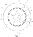
- reference numeral 1 indicates a brake disk as a whole according to the present invention.
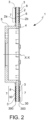
- the disk brake 1 comprises a braking band 2, provided with two opposed braking surfaces 2a and 2b, each of which at least partially defines one of the two main faces of the disk.
- the braking band 2 consists of a base metal chosen from gray cast iron or steel.
- the braking band is made of gray cast iron.
- the entire disk is made of gray cast iron. Therefore, in the following description, reference will be made to a disk made of gray cast iron, without however excluding the possibility that it is made of steel.
- the disk 1 is provided with:
- the base protective coating 30 is constituted of chromium carbide (Cr3C2) and nickel-chromium (NiCr), or of nickel-chromium (NiCr), iron (Fe), molybdenum (Mo), cobalt (Co), manganese (Mn), and aluminum (Al), and is obtained by a spray deposition technique on the disk 1, preferably HVOF (High-Velocity Oxygen Fuel) technique, or HVAF (High-Velocity Air Fuel) technique or KM (Kinetic Metallization) technique of the components of the coating in particle form.
- HVOF High-Velocity Oxygen Fuel
- HVAF High-Velocity Air Fuel
- the surface protective coating 3 consists of tungsten carbide (WC), iron (Fe), chromium (Cr), and aluminum (Al) and is obtained by depositing tungsten carbide (WC), iron (Fe), chromium (Cr), and aluminum (Al) in particle form on the base protective coating 30 by means of spraying technique, preferably with HVOF (High-Velocity Oxygen Fuel) technique or by HVAF (High-Velocity Air Fuel) technique or by KM (Kinetic Metallization) technique.
- HVOF High-Velocity Oxygen Fuel
- HVAF High-Velocity Air Fuel
- the braking surface coated by the aforesaid base protective coating 3 is defined by a nitrocarburized layer 300 of the base metal (gray cast iron or steel) and has a rough profile in radial or circumferential cross-section relative to the center of the braking band.
- the protective base layer 30 is therefore fixed not directly onto the base metal which forms the braking band but is fixed on the aforementioned nitrocarburized base metal layer 300.
- the aforesaid rough profile is defined by a plurality of protuberances 20 which extend orthogonally to the surface with a height between 30 and 200 ⁇ m and are mutually spaced apart - in a radial or circumferential direction relative to the center of the braking band - with a pitch between 300 and 2000 ⁇ m.
- the aforesaid protrusions are distributed in a regular pattern over the braking surface of disk 1.
- an irregular distribution pattern may also be provided.
- the aforementioned projections 20 have a profile which will be described in greater detail below.
- the aforesaid rough profile may have a roughness Ra between 0.8 and 2, if obtained by turning, or a roughness Rz between 10 and 80, if obtained by sandblasting.
- the aforesaid nitrocarburized layer 300 is obtained by a ferritic nitrocarburization treatment of the base metal.
- the nitrocarburized layer 300 has a depth comprised between 2 and 30 ⁇ m and hardness values higher than 300 HV in microhardness.
- the aforesaid nitrocarburized layer 300 comprises an oxidized top layer 330 comprising magnetite Fe3O4 which acts as an interface with the aforesaid protective base layer 30.
- the aforementioned oxidized top layer 330 comprising magnetite Fe3O4 has a thickness comprised between 2 and 10 ⁇ m.
- the base protective coating 30 is constituted by:
- the base protective coating 30 may have the following compositions:
- the base protective coating 30 consists of from 75% by weight of chromium carbide (Cr3C2) and of 25% of nickel-chromium (NiCr).
- the nickel-chromium (NiCr) consists of from 80% of nickel and of 20% chromium.
- the surface protective coating 3 consists of from 75% to 87% by weight of tungsten carbide (WC) and iron (Fe), chromium (Cr), and aluminum (Al) for the rest. Even more preferably, the surface protective coating 3 consists of 85% by weight of tungsten carbide (WC) and 15% by weight of iron (Fe), chromium (Cr), and aluminum (Al).
- the thickness of the base protective coating 20 is comprised between 20 um and 80 ⁇ m, and preferably equal to 50 um, while the thickness of the surface protective coating 3 is comprised between 30 um and 90 ⁇ m, and preferably equal to 60 um.
- the thickness of the two protective coatings 3 and 30 is calculated relative to the portions of the coating above the rough state. These are therefore minimum thickness values which do not take into account the thickness of the coating which may be used to fill the dips/pits of the roughness.
- the two protective coatings 3 and 30 completely fill the roughness of the braking surface and develop over the rough profile with layers of thickness preferably within the intervals specified above.
- nitrocarburized layer 300 at the interface between the unmodified base metal and the protective base coating 30 allows a significant reduction, if not a complete cancellation, of the occurrence of coating flaking phenomena, relative to brake disks with similar protective coatings but without a nitrocarburized layer.
- the nitrocarburized layer protects the base metal from corrosion without, however, being made up of a layer of material applied onto the base metal itself. In other words, there is no net separation area between the unmodified base metal and the nitrocarburized layer 300.
- the nitrocarburized layer is indeed a layer of the base metal morphologically and chemically modified by a process of nitrocarburization. The transition from unmodified base metal to nitrocarburized metal may therefore be progressive.
- the roughness profile of the braking surface, where the nitrocarburized layer 300 is made further accentuates the irregularity in the transition from nitrocarburized to the unmodified base metal, thereby boosting the positive effects.
- the roughness profile of the braking surface, where the nitrocarburized layer 300 is made, further facilitates the mechanical adhesion of the base protective layer 30 to the nitrocarburized layer.
- nitrocarburized layer 300 does not affect the performance of the protective surface coating 3 in terms of both wear resistance and tribological behavior (friction, fading, running-in) under normal environmental conditions.
- nitrocarburized layer 300 comprises an oxidized top layer 330 comprising magnetite Fe3O4.
- Such an anti-corrosion action is in any case further enhanced by the presence of the base coating layer 30.
- a protective base coating 30 Cr3C2 and NiCr, or NiCr, Fe, Mo, Co, Mn, and Al
- such a base coating 30 also has an anti-corrosive effect on the braking surface of the disk.
- the anti-corrosive action goes to the benefit of the integrity and the adhesion of the surface protective coating 3 to the disk.
- the base protective coating 30 also performs a mechanical "damper" function for the surface protective (anti-wear) coating 3.
- the base protective coating 30 formed by Cr3C2 and NiCr or by NiCr, Fe, Mo, Co, Mn, and Al has a higher degree of ductility than the surface protective coating 3 formed by tungsten carbide, iron, chromium, and aluminum. This confers an elastic behavior to the base layer 30 which helps mitigate - at least in part - the stresses imparted to the disk when in use. Therefore, the base protective coating 30 acts as a sort of damper or cushion between the disk and the surface protective coating 3. This prevents direct transmission of stresses between the two parts, thereby reducing the risk of triggering cracks in the surface protective coating 3.
- the surface protective coating 3 is biased neither by the presence of the base protective coating 30 nor by the nitrocarburized layer 300 (possibly with oxidized top layer 330).
- the brake disk 1 is made preferably, but not necessarily, with the method according to the invention described below.
- the method comprises the following operating steps:
- step b) may be performed to generate on the aforesaid surface a rough profile defined by a plurality of protuberances 20 which extend orthogonally to the surface with a height h between 30 and 200 ⁇ m and are mutually spaced apart - in a radial or circumferential direction relative to the center of the braking band - with a pitch P between 300 and 2000 ⁇ m.
- projections 20 have a profile which will be described in greater detail below. The presence of this profile increases the mechanical adhesion capacity of the basic protective coating 30 on the nitrocarburized layer 300.
- step b) is carried out with the working process by chip removal or by laser incision or by plastic deformation.
- step b) may alternatively be carried out with a working process by fine turning with roughness Ra between 0.8 and 2.
- step b) is carried out with the working process by sandblasting with roughness Rz between 10 and 80.
- the step (c) of nitrocarburization is obtained by a ferritic nitrocarburization treatment.
- the nitrocarburization step c) is carried out so that the nitrocarburized surface layer 300 has a depth between 2 and 30 ⁇ m and hardness values higher than 300 HV in microhardness.
- step c) of nitrocarburizing is followed by step f) of post-oxidation of the nitrocarburized layer 300, performed before step d) of deposition, to obtain an oxidized top layer 330 comprising magnetite Fe3O4.
- the oxidized top layer 330 comprising magnetite (Fe3O4) has a thickness comprised between 2 and 10 ⁇ m.
- Nitrocarburization is a process well known in itself to a person skilled in the art and will therefore not be described in detail. Here we limit our to providing some general information for clarification.
- Nitrocarburization is a thermochemical surface hardening process conducted in ferritic phase at relatively low temperatures (550°C-580°C) and under such conditions as to obtain a diffusion of nitrogen and carbon in the surface area of the piece.
- the means adopted in implementing the process of diffusion of nitrogen and carbon are: salt baths; gas; plasma.
- Nitrocarburization with a gaseous medium is preferred over nitrocarburization in a salt bath when a high degree of uniformity and cleanliness is sought (blind cavities, grooves, threads, etc.).
- the temperatures adopted in the nitrocarburization process guarantee the containment of deformations.
- ferritic nitrocarburization an ion nitrocarburization can be implemented. The latter differs from the ferritic one essentially for the temperature which is 570°C and the atmosphere which is made up of ammonia and methane.
- the material in particle form deposited in the step d) of depositing for making the base protective coating 30 consists of from 65% to 95% of chromium carbide (Cr3C2) and nickel-chromium (NiCr) for the rest.
- the material in particle form deposited in step b) of depositing for making the base protective coating 30 may have the following compositions:
- the material in particle form deposited in the step d) of depositing for making the base protective coating 30 consists of 75% by weight of chromium carbide (Cr3C2) and 25% of nickel-chromium (NiCr).
- the nickel-chromium (NiCr) consists of from 80% of nickel and of 20% chromium.
- the material in particle form deposited in the deposition step d) to make the base protective coating 30 is based on nickel-chromium (NiCr) with a content by weight of nickel (Ni) from 40% to 75% and with a content by weight of chromium (Cr) from 14% to 30%, and for the remainder of iron (Fe), molybdenum (Mo), cobalt (Co), manganese (Mn) and aluminum (Al).
- the material in particle form deposited in the step e) of depositing for making the surface protective coating 3 consists of from 75% to 87% by weight of tungsten carbide (WC) and iron (Fe), chromium (Cr), and aluminum (Al) for the rest.
- the material in particle form deposited in the step e) of depositing for making the surface protective coating 3 consists of from 10% to 17% by weight of iron (Fe), from 2.5% to 5.8% by weight of chromium (Cr), from 0.6% to 2.2% by weight of aluminum (Al) and the rest by tungsten carbide (WC).
- the surface protective coating 3 which is obtained consists of 85% by weight of tungsten carbide (WC) and 15% by weight of iron (Fe), chromium (Cr), and aluminum (Al).
- the brake disk is provided with a portion adapted to fix the disk to a vehicle, constituted by an annular portion or fixing portion 4 which is arranged centrally relative to the disk 1 and concentric to the braking band 2.
- the fixing portion 4 supports the connection element 5 to the wheel hub (i.e. the bell).
- the bell may be formed in one piece with the annular fixing portion (as shown in the accompanying figures) or may be formed separately and then fixed by means of appropriate connecting elements to the fixing portion.
- the annular fixing portion 4 can be made of the same material as the braking band, i.e. of gray cast iron, or steel.
- the bell 5 can also be made of aluminum or gray cast iron or other appropriate material.
- the entire disk i.e. the braking band, fixing portion, and bell
- the braking band 2 is made by casting.
- the fixing portion and/or the bell may be produced by casting.
- the annular fixing portion can be made in a single body with the braking band (as shown in the accompanying figures) or can be made as a separate body, mechanically connected to the braking band.
- the material in particle form which is deposited in step d) for forming the base protective coating 30 has a particle size comprised between 5 and 40 um.
- the choice of such a range of values makes it possible to confer high properties of deposition surface density and adhesion capacity to the nitrocarburized layer 300.
- the thickness of the base protective coating 30 is comprised between 20 um and 80 ⁇ m, and preferably equal to 50 um.
- the choice of such a range of values makes it possible to achieve an optimum balance between the effectiveness of the anti-oxidizing protective action and limitation of the thermal expansions on the coating itself. In other words, if the thickness of the base protective coating 30 were less than 20 ⁇ m, there would not be a sufficient anti-oxidizing protective action.
- a thickness greater than 80 ⁇ m could lead in time to an imperfect adhesion due to thermal expansions which occur during the life cycle of a disk brake.
- the base protective coating 30 can perform the aforementioned "damper" effect which helps preserve the integrity of the surface protective coating 3.
- the material in particle form which is deposited in step e) for forming the surface protective coating 3 has a particle size comprised between 5 and 45 um.
- the choice of such a range of values makes it possible to confer high properties of density, hardness and limited porosity to the coating.
- the thickness of the surface protective coating 3 is comprised between 30 um and 90 ⁇ m, and preferably equal to 60 um.
- the choice of such a range of values makes it possible to achieve an optimum balance between the consumption of the protective layer and the limitation of the thermal expansions on the coating itself. In other words, if the thickness of the protective coating were less than 20 ⁇ m, in case of wear, it would be totally removed in an excessively short time.
- a thickness greater than 90 um could lead in time to an imperfect adhesion due to thermal expansions which occur during the life cycle of a disk brake.
- the thickness of the two protective coatings 3 and 30 is calculated in relation to the portions of the coating above the rough state. These are therefore minimum thickness values which do not take into account the thickness of the coating which may be used to fill the dips/pits of the roughness.
- the two protective coatings 3 and 30 completely fill the roughness of the braking surface and develop over the rough profile with layers of thickness preferably within the intervals specified above.
- both the material which forms the base protective coating 30 chromium carbide (Cr3C2) and nickel-chromium (NiCr), or nickel-chromium (NiCr), iron (Fe), molybdenum (Mo), cobalt (Co), manganese (Mn) and aluminum (Al)
- the material forming the surface protective coating 3 tungsten carbide, iron, chromium, and aluminum
- HVOF technique tungsten carbide, iron, chromium, and aluminum
- HVOF High-Velocity Oxygen Fuel
- a powder spray deposition technique which uses a spray device provided with a mixing and combustion chamber and with a spray nozzle. Oxygen and fuel are fed to the chamber.
- the hot combustion gas which forms at pressures close to 1 MPA crosses the convergent-divergent nozzle conveys the material in powder to hypersonic speed (i.e. higher than MACH 5).
- the material in powder to be deposited is injected into the hot gas flow, in which it melts rapidly and is accelerated to a speed of the order of 1000 m/s. Once it has impacted onto the deposition surface, the molten material cools rapidly and a very dense and compact structure is formed by virtue of the high kinetic energy impact.
- the HVAF (High-Velocity Air Fuel) deposition technique is similar to the HVOF technique. The difference is that air instead of oxygen is supplied into the combustion chamber in the HVAF technique. Therefore, the temperatures in hand are lower than those of the HVOF technique. This allows better control of the thermal alteration of the coating.
- the KM (Kinetic Metallization) deposition technique is a solid-state deposition process in which metal powders are sprayed through a sonic deposition nozzle in two steps which accelerate and triboelectrically charge the metal particles in an inert gas flow. Thermal energy is supplied in the carrier stream. The potential energy of the compressed inert gas flow and of the thermal energy is converted into kinetic energy of the powders in the process. Once accelerated at high speed and electrically charged, the particles are directed against the deposition surface. The high-speed collision of the metal particles with such a surface causes large deformation of the particles (approximately 80% in a direction perpendicular to the impact). This deformation results in an enormous increase in the surface area of the particles. As an effect of the impact, intimate contact is formed between the particles and the deposition surface, which leads to the formation of metallic bonds and a coating having a very dense and compact structure.
- the aforesaid combination allows to obtain a high anchoring degree both of the base coating 30 on the nitrocarburized layer 300 (possibly with oxidized top layer 330), and of the surface coating 3 on the protective base coating 30.
- both the material in particle form deposited in the step d) of depositing for making the base protective coating 3 and the material in particle form deposited in the step e) of depositing for making the surface protective coating 30 are deposited by means of HVOF (High-Velocity Oxygen Fuel) technique.
- HVOF High-Velocity Oxygen Fuel
- the HVAF High-Velocity Air Fuel
- the HVAF High-Velocity Air Fuel
- the base protective coating made of Cr3C2 + Ni or NiCr + Fe+ Mo+ Co+ Mn + Al did not suffer consequences following the thermal shock test, always being dense, perfectly adhered to the cast iron, and free from cracks.
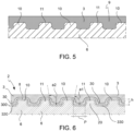
- the base protective coating 30 and the surface protective coating 3 cover at least one of the two braking surfaces of the braking band.
- the disk 1 is provided with a "combined protective coating" 3, 30 which covers both braking surfaces 2a and 2b of the braking band 2.
- the combined protective coating 3, 30 may cover only the braking band, on a single braking surface, or both.
- the combined protective coating 3, 30 may extend also to other parts of the disk 1 as the annular fixing portion 4 and the bell 5, to cover the entire surface of the disk 1.
- the combined protective coating 3, 30 may cover - in addition to the braking band - only the fixing portion or only the bell. The choice is substantially dictated by reasons of appearance, to have a uniform coloring and/or finishing on the entire disk or between some portions of it.
- the particle material depositing for the formation of the combined protective coating 3, 30 may be performed in a differentiated manner on the surface of the disk at least in terms of the coating thickness.
- the combined protective coating 3, 30 can be made with the same thickness in the two opposite braking surfaces. Alternative solutions can be provided in which the combined protective coating 3, 30 is made by differentiating the different thicknesses between the two braking surfaces of the braking band.
- the step d) of depositing for forming the base protective coating 30 comprises two or more distinct deposition stages of the particle chromium carbide on the surface itself to form the protective coating.
- step d) of deposition comprises:
- the second finishing layer makes it possible to adjust the surface finish of the base protective coating 3.
- step d) of depositing makes it possible, in particular, to differentiate at least the particle size of the material in particle form used in the various stages. This makes the step d) of depositing more flexible.
- the particle material deposited in particle form in the first deposition stage has a particle size greater than that deposited in the second deposition stage.
- the particle material deposited in particle form in the first deposition stage has a particle size comprised between 30 and 40 um, while the particle material deposited in particle form in the second deposition stage has a particle size comprised between 5 and 20 ⁇ m.
- the base protective coating 30 in two distinct deposition stages using a coarser particle size for the formation of the first layer and a finer particle size for the formation of the second layer (with finishing function), makes it possible to obtain a coating which already at the end of the deposition has the required surface finish features, as a function of the subsequent deposition of the surface protective coating 3. Such desired surface finishing characteristics can be obtained without needing to grind and/or perform other surface finishing operations for the coating.
- the particles deposited in the second stage fill the coarse roughness on the surface of the base layer.
- the surface finishing level of the coating can be adjusted by adjusting the particle size of the particles deposited in the second stage.
- the thickness of the first layer of the protective base coating 30 is comprised between 2/4 and 3/4 of the total thickness of the coating, while the thickness of the second layer of the protective base coating 4 is comprised between 1/4 and 2/4 of the total thickness of the coating.
- the step e) of depositing of the particle material (WC + Fe + Cr + Al) which forms the surface protective coating 3 comprises two or more distinct deposition stages of the particle material onto the same surface to form the protective coating.
- said step e) of deposition comprises:
- surface protection layer 3 is subjected to a step of surface finishing to achieve the desired final degree of roughness.
- the surface finish of protective layer 3 may be obtained by working directly on the deposition methods of the coating itself 3.
- step e) of depositing of the particle material which forms the surface protective coating 3 into two or more stages, in particular, also makes it possible to differentiate between at least the particle size of the particle material used in the various steps. This makes the step e) of depositing more flexible.
- the particle material deposited in the first deposition stage has a particle size greater than that deposited in the second deposition stage.
- the particle material deposited in the first deposition stage has a particle size comprised between 30 and 40 ⁇ m, while the particle material deposited in the second deposition stage has a particle size comprised between 5 and 20 ⁇ m.
- the embodiment of the protective coating or surface 3 with two distinct deposition stages using a coarser particle size for forming the base layer and a finer grain size for forming the finishing layer, makes it possible to obtain a surface protective coating 3 which already at the end of the deposition has the required surface finishing features, without the need for grinding and/or performing other surface finishing operations for the coating.
- the particles deposited in the second stage fill the coarse roughness on the surface of the base layer.
- the surface finishing level of the surface protection 3 can be adjusted by adjusting the particle size of the particles deposited in the second stage.
- the surface protective coating 3 has at the finishing layer a surface roughness Ra in the range between 2.0 and 3.0 ⁇ m.
- the thickness of the first layer of the surface protective coating 3 is comprised between 2/4 and 3/4 of the total thickness of the coating, while the thickness of the second layer of the surface protective coating 3 is comprised between 1/4 and 2/4 of the total thickness of the coating.
- the combination of the HVOF, HVAF, or KM deposition techniques of the particle material, of the chemical components used, and the method of depositing in multiple stages makes it possible to obtain a coating with a limited level of surface roughness, particularly adapted for the purposes of use of the brake disk 1.
- the two disks were subjected to the usual dynamic bench tests (run-in, AK Master and wear).
- the performance of the disk according to the invention is substantially comparable to that of a traditional disk B.
- the two disks were also subjected to a series of resistance tests in the presence of combined and environmental thermomechanical stresses.
- the two disks were subjected to a test program which envisages the repetition of combined dynamic bench tests (the disk was subjected to different cycles of braking, each with multiple consecutive braking operations) and tests in a corrosive environment (salt spray and condensation water test: disk and brake pads were kept in salt spray and an environment with a high degree of moisture with high-temperature excursions).
- the disk brake and the method for making such disk brake according to the invention makes it possible to overcome the disadvantages of the prior art.
- the brake disks made according to the invention are not subject to flaking or are subject to it to a much lesser degree than the known solutions (to ensure in time a wear resistance) and at the same time do not contain cobalt.
- the brake disk coated with a nitrocarburized layer according to the invention displayed similar wear resistance and tribological behavior under normal environmental conditions relative to similar coated disks without a nitrocarburized layer.
- the brake disk coated according to the invention has the best performance in terms of strength in presence of environmental stresses (thermal shocks and salt attacks).
- the brake disk 1 is also generally cost-effective to make.
- a braking band 2 of a disk for a disk brake 1 is provided.
- Said braking band 2 extends between an inner diameter D1, near a rotation axis X-X of the braking band 2, and an outer diameter D2, far from said rotation axis X-X.
- Said rotation axis defines an axial direction X-X.
- Said braking band 2 defines a radial direction R-R, which is substantially orthogonal to said axial direction X-X, and a circumferential direction C-C which is orthogonal both to said axial direction X-X and to said radial direction R-R.
- a brake band 2 of a disk brake disk 1 comprises an annular band body 6 arranged about a brake disk rotational axis, or brake disk rotation axis X-X.
- Said band body 6 is made of gray cast iron or steel or aluminum or alloys thereof.
- Said braking band 2 comprises at least one braking surface 2a or 2b.
- At least one portion of said at least one braking surface 2a or 2b comprises an activated band body portion 7 for increasing the adhesive capacity of at least one protective surface coating 3 placed on the surface of said activated band body portion 7.
- Said protective surface coating 3 comprises at least one material with elevated resistance to abrasion.
- Said activated band body portion 7 is arranged on the surface of said band body 6 to form an outermost layer of the braking band 2 with said at least one protective surface coating 3.
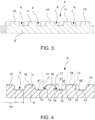
- Said activated band body portion 7 comprises a rough profile 8.
- Said rough profile 8 comprises at least one groove or channel 9 delimited by at least one pair of projections 10 and/or 11 and/or 12.
- Said at least one channel 9 extends along a path, which surrounds, at least partially, said rotation axis X-X.
- Said at least one channel 9 has a channel bottom 13 and two opposite channel sides 14, 15 in the cross-section, at the longitudinal extension thereof.
- a first channel side 14 forms an acute angle a1 with said channel bottom 13, i.e. an angle a1 smaller than 90 DEG.
- a second channel side 15 forms an obtuse angle a2 with said channel side 13, i.e. an angle a2 larger than 90 DEG.
- said first and second channel side 14, 15 are mutually parallel sides.
- said first channel side 14 forms an acute angle a1 of 80 DEG with said channel bottom 13.
- said second channel side 15 forms an obtuse angle (a2) of 100 DEG with said channel bottom 13.
- said projection is a first projection 10, which forms undercuts 17 on both projection sides thereof.
- said projection is a second projection 11, which delimits channel sides 15, both forming obtuse angles a2 with the respective channel bottoms 13.
- said projection is a third projection 12, which delimits a first channel side 14, forming an acute angle a1 with the channel bottom 15 and a second opposite channel side 13, forming an obtuse angle a2 with the channel bottom 13.
- said at least one pair of projections 10 and/or 11 and/or 12 is a plurality of projections 20, which alternate, in particular, a first projection 10 and a second projection 11.
- said at least one pair of projections 12 is a plurality of projections 20, which are all equal, in particular, a third projection plurality 12.
- said at least one pair of projections 11 and/or 12 is a plurality of projections 20 comprising:
- said at least one channel 9 is a first pair of channels 9, set side by side to each other and delimited by a first projection 10 placed between said pair of channels 9; said projection delimits, with both opposite edges thereof, channel sides 14, both forming an acute angle a1 with said channel bottom 13.
- said at least one channel 9 is a first pair of channels 9, set side by side to each other and delimited by a first projection 10 placed between said pair of channels 9; said projection delimits, with both opposite edges thereof, channel sides 14, forming undercut channel portions 17, i.e. deeper cavities, which form an acute angle a1 with the plane made up of the channel bottom 13.
- said at least one channel 9 is a second pair of channels, set side by side to each other and delimited by a second projection 11, placed between said channels 9; said projection delimits, with both opposite edges thereof, channel sides 15, both forming an obtuse angle a2 with said channel bottom 13.
- said at least one channel 9 is a third pair of channels, set side by side to one another and delimited by a third projection 11, placed between said channels set side by side; said third projection 11 delimits, with both opposite edges thereof, channel sides 14, 15, with a first side 14 forming an acute angle a1 with said channel bottom 13, and with a second side 15 forming an obtuse angle a2 with said channel bottom 13.
- said third projection 11 forms, on both sides thereof, facing said channels 9 set side by side, channel sides 14, 15, parallel to each other.
- said third projection 11, which forms a first side 14 with an acute angle a1 to said channel bottom 13 has said first side 14 inclined, forming an undercut 17 facing or pointing at said rotation axis X-X.
- said third projection 11, which forms a first side 14 with an acute angle a1 to said channel bottom 13 has said first side 14 inclined, forming an undercut 17 facing opposite or pointing away from said or pointing at the side opposite said rotation axis X-X.
- said activated band body portion 7 is two braking band portions comprised in the same braking band 2; wherein
- a first projection 10 forming undercuts 17 on both sides thereof and a second projection 11 delimiting channel sides 15, both forming obtuse angles a2 with the respective channel bottoms 13, alternate to form a plurality of channels 9 in said rough profile 8.
- said channel 9 has a depth from 0.05 mm to 0.1 mm, preferably 0.075 mm and a width comprised from 0.5 mm to 0.7 mm.
- said projection 10 or 11 or 12 has a width which is substantially identical to the width of said channel 9.
- said channel bottom 13 is a substantially flat surface.
- said projection 10 or 11 or 12 is delimited externally by a projection ridge 18, wherein said projection ridge 18 is a substantially flat surface.
- said projection 10 or 11 or 12 is delimited externally by a projection ridge 18 and wherein said channel sides 14, 15 are joined to said projection ridge with a connecting radius from 0.1 mm to 0.4 mm.
- said channel sides 14, 15 are joined to said channel bottom 13 with a connection and wherein said connection has a connecting radius from 0.01 mm to 0.02 mm.
- said band body 6 is formed by a base metal selected from gray cast iron or steel, wherein:
- the present invention further relates to a disk brake disk 1 comprising a braking band 2 as defined by any one of the previously described embodiments and a bell 5 associated with said braking band 2 and adapted to connect to a wheel hub of a vehicle.
- the present invention further relates to a vehicle comprising a disk brake disk 1 as described above.
- a method for producing a braking band 2 comprises the following operating steps:
- the present invention relates to a tool 21 for producing the activated band according to one of the previously described embodiments, comprising at least one cutting edge 22, which comprises a rough profile defining at least one cutting edge projection 23 having at least one cutting edge ridge 24, a first cutting edge side 25 and a second cutting edge side 26; Evaluated parallel to said cutting edge ridge 24, said cutting edge has a maximum cutting edge projection width 27 smaller than a maximum channel width 16.
- said tool 21 comprises a plurality of cutting edge projections 28 side by side.
Landscapes
- Chemical & Material Sciences (AREA)
- Engineering & Computer Science (AREA)
- Mechanical Engineering (AREA)
- Metallurgy (AREA)
- Organic Chemistry (AREA)
- Chemical Kinetics & Catalysis (AREA)
- Materials Engineering (AREA)
- General Engineering & Computer Science (AREA)
- Physics & Mathematics (AREA)
- Plasma & Fusion (AREA)
- Inorganic Chemistry (AREA)
- Transportation (AREA)
- Braking Arrangements (AREA)
- Coating By Spraying Or Casting (AREA)
- Other Surface Treatments For Metallic Materials (AREA)
Claims (20)
- Bremsband (2) einer Scheibe für eine Scheibenbremse (1), wobei das Bremsband (2) einen ringförmigen Bandkörper (6) aufweist, der um eine Bremsscheibendrehachse oder Drehachse (X-X) herum angeordnet ist;wobei der Bandkörper (6) aus Graugusseisen oder Stahl oder Aluminium oder Legierungen davon hergestellt ist;wobei das Bremsband (2) zumindest eine Bremsfläche (2a oder 2b) aufweist;wobei zumindest ein Abschnitt der zumindest einen Bremsfläche (2a oder 2b) einen aktivierten Bandkörperabschnitt (7) aufweist, um die Haftkapazität von zumindest einer Schutzoberflächenbeschichtung (3) zu erhöhen, die auf der Oberfläche des aktivierten Bandkörperabschnitts (7) platziert ist,wobei die Schutzoberflächenbeschichtung (3) zumindest ein Material mit erhöhter Abriebbeständigkeit aufweist,und wobei der aktivierte Bandkörperabschnitt (7) auf der Oberfläche des Bandkörpers (6) angeordnet ist, um eine äußerste Schicht des Bremsbandes (2) mit der zumindest einen Schutzoberflächenbeschichtung (3) zu bilden;und wobei der aktivierte Bandkörperabschnitt (7) ein raues Profil (8) aufweist;wobei das raue Profil (8) zumindest eine Nut oder einen Kanal (9) aufweist, die oder der durch zumindest ein Paar von Vorsprüngen (10 und/oder 11 und/oder 12) begrenzt ist;wobei sich der zumindest eine Kanal (9) entlang einen Weges erstreckt, der die Drehachse (X-X) zumindest teilweise umgibt;und wobei der zumindest eine Kanal (9) an seiner Längserstreckung, im Querschnitt einen Kanalboden (13) und zwei gegenüberliegende Kanalseiten (14, 15) aufweist,dadurch gekennzeichnet, dasseine erste Kanalseite (14) mit dem Kanalboden (13) einen spitzen Winkel (a1) bildet, d.h. einen Winkel (a1) kleiner als 90 Grad;eine zweite Kanalseite (15) mit der Kanalseite (13) einen stumpfen Winkel (a2) bildet, d.h. einen Winkel (a2) größer als 90 Grad;und wobei das zumindest eine Paar von Vorsprüngen (10 und/oder 11und/oder 12) eine Breite hat, die mit der Breite des Kanals (9) im Wesentlichen identisch ist.
- Bremsband (2) nach Anspruch 1, wobei
die ersten und zweiten Kanalseiten (14, 15) zueinander parallele Seiten sind. - Bremsband (2) nach Anspruch 1, wobeidie erste Kanalseite (14) mit dem Kanalboden (13) einen spitzen Winkel (a1) von 80 Grad bildet;und/oder wobeidie zweite Kanalseite (15) mit dem Kanalboden (13) einen stumpfen Winkel (a2) von 100 Grad bildet.
- Bremsband (2) nach Anspruch 1, wobeider Vorsprung ein erster Vorsprung (10) ist, der an seinen beiden Vorsprungsseiten Unterschnitte (17) bildet;
oderder Vorsprung ein zweiter Vorsprung (11) ist, der die Kanalseiten (15) begrenzt, die beide mit den jeweiligen Kanalböden (13) stumpfe Winkel (a2) bilden;
oderder Vorsprung ein dritter Vorsprung (12) ist, der eine erste Kanalseite (14), die mit dem Kanalboden (15) einen spitzen Winkel (a1) bildet, sowie eine zweite gegenüberliegende Kanalseite (13), die mit dem Kanalboden (13) einen stumpfen Winkel (a2) bildet, begrenzt. - Bremsband (2) nach Anspruch 4, wobeidas zumindest eine Paar von Vorsprüngen (10 und/oder 11 und/oder 12) eine Mehrzahl von Vorsprüngen (20) ist, die insbesondere einen ersten Vorsprung (10) und einen zweiten Vorsprung (11) abwechseln;
oderdas zumindest eine Paar von Vorsprüngen (12) eine Mehrzahl von Vorsprüngen (20) ist, die alle gleich sind, insbesondere eine dritte Vorsprungsmehrzahl (12);
oderdas zumindest eine Paar von Vorsprüngen (11 und/oder 12) eine Mehrzahl von Vorsprüngen (20) ist, welche aufweist:- eine erste dritte Vorsprungsmehrzahl (12); und- eine zweite dritte Vorsprungsmehrzahl (12), aber diese zweite Mehrzahl ein Profil hat, d. h. einen Querschnitt an seiner Längserstreckung jedes Vorsprungs der zweiten Mehrzahl, das dem Profil der ersten Mehrzahl entgegengesetzt ist; und- ein zweiter Vorsprung (11) zwischen die ersten und zweiten Mehrzahlen eingefügt ist. - Bremsband (2) nach Anspruch 1,wobei der zumindest eine Kanal (9) ein erstes Paar von Kanälen (9) ist, die nebeneinander liegen und durch einen ersten Vorsprung (10) begrenzt sind, der zwischen dem Paar von Kanälen (9) platziert ist; wobei der Vorsprung, mit seinen entgegengesetzten Rändern Kanalseiten (14) begrenzt, die beide mit dem Kanalboden (13) einen spitzen Winkel (a1) bilden;
oderder zumindest eine Kanal (9) ein erstes Paar von Kanälen (9) ist, die nebeneinander liegen und durch einen ersten Vorsprung (10) begrenzt sind, der zwischen dem Paar von Kanälen (9) platziert ist; wobei der Vorsprung mit seinen beiden entgegengesetzten Rändern Kanalseiten (14) begrenzt, die unterschnittene Kanalabschnitte (17) bilden, d.h. tiefere Ausnehmungen, die mit der aus dem Kanalboden (13) gebildeten Ebene einen spitzen Winkel (a1) bilden. - Bremsband (2) nach Anspruch 1, wobeider zumindest eine Kanal (9) ein zweites Paar von Kanälen ist, die nebeneinander liegen und durch einen zweiten Vorsprung (11) begrenzt sind,der zwischen den Kanälen (9) platziert ist; wobei der Vorsprung mit seinen entgegengesetzten Rändern Kanalseiten (15) begrenzt, die beide mit dem Kanalboden (13) einen stumpfen Winkel (a2) bilden.
- Bremsband (2) nach Anspruch 1, wobeider zumindest eine Kanal (9) ein drittes Paar von Kanälen ist, die nebeneinander liegen und durch einen dritten Vorsprung (11) begrenzt sind, der zwischen den nebeneinander liegenden Kanälen platziert ist; wobei der dritte Vorsprung (11) mit seinen entgegengesetzten Rändern Kanalseiten (14, 15) begrenzt, die an einer ersten Seite (14) einen spitzen Winkel (a1) mit dem Kanalboden (13) und an einer zweiten Seite (15) einen stumpfen Winkel (a2) mit dem Kanalboden (13) bilden;und/oder wobeider dritte Vorsprung (11) an seinen beiden Seiten, die zu den nebeneinander liegenden Kanälen (9) weisen, zueinander parallele Kanalseiten (14, 15) bildet.
- Bremsband (2) nach Anspruch 8, wobeider dritte Vorsprung (11), der eine erste Seite (14) mit einem spitzen Winkel (a1) zu dem Kanalboden (13) bildet, die schräge erste Seite (14) aufweist, die einen Unterschnitt (17) bildet, der zu der Drehachse (X-X) weist oder zeigt;oder wobeider dritte Vorsprung (11), der eine erste Seite (14) mit einem spitzen Winkel (a1) zu dem Kanalboden (13) bildet, die schräge erste Seite (14) aufweist, die einen Unterschnitt (17) bildet, der entgegen der Drehachse (X-X) weist oder von dieser weg zeigt oder zu der davon entgegengesetzten Seite zeigt.
- Bremsband (2) nach Anspruch 8, wobeider aktivierte Bandkörperabschnitt (7) zwei Bremsbandabschnitte ist, die in demselben Bremsband (2) liegen; wobeinur dritte Vorsprünge (11) mit zueinander parallelen Seiten (14, 15) in einem ersten Abschnitt liegen, die eine erste Seite (14) mit einem spitzen Winkel (a1) zu dem Kanalboden (13) bilden, dessen erste Seite (14) geneigt ist, unter Bildung eines Unterschnitts (17), die zu der Drehachse (X-X) weist oder zeigt;dritte Vorsprünge (11) mit zueinander parallelen Seiten (14, 15) in einem zweiten Abschnitt, der eine erste Seite (14) mit einem spitzen Winkel (a1) zu dem Kanalboden (13) bilden und die schräge erste Seite (14) aufweist und einen Unterschnitt (17) bildet, der entgegen der Drehachse (X-X) weist oder von dieser weg zeigt oder zu der davon entgegengesetzten Seite zeigt
- Bremsband (2) nach Anspruch 1, wobei
der erste Vorsprung (10) an seinen beiden Seiten Unterschnitte (17) bildet und ein zweiter Vorsprung (11) Kanalseiten (15) begrenzt, die beide mit den jeweiligen Kanalböden (13) stumpfe Winkel (a2) bilden, abwechselnd, zur Bildung einer Mehrzahl von Kanälen (9) in dem rauen Profil (8) . - Bremsband (2) nach Anspruch 1, wobei der Kanal (9) hat eine Tiefe von 0,05 mm bis 0,1 mm hat, bevorzugt von 0,075 mm, und eine Breite von 0,5 mm bis 0,7 mm;und/oder wobeider Vorsprung (10 oder 11 oder 12) eine Breite hat, die mit der Breite des Kanals im Wesentlichen identisch (9) ist;und/oder wobeider Kanalboden (13) eine im Wesentlichen flache Oberläche ist.
- Bremsband (2) nach Anspruch 1, wobeider Vorsprung (10 oder 11 oder 12) außen durch eine Vorsprungsrippe (18) begrenzt ist, wobei die Vorsprüngsrippe (18) eine im wesentlichen flache Oberfläche ist,
und/oderder Vorsprung (10 oder 11 oder 12) außen durch eine Vorsprungsrippe (18) begrenzt ist und wobei die Kanalseiten (14, 15) mit der Vorsprungsrippe mit einem Verbindungsradius von 0,1 mm bis 0,4 mm verbunden sind;und/oder wobeidie Kanalseiten (14, 15) mit dem Kanalboden (13) mit einer Verbindung verbunden sind, und wobei die Verbindung einen Verbindungsradius von 0,01 mm bis 0,02 mm hat. - Bremsband (2) nach Anspruch 1, wobeider Bandkörper (6) aus einem Basismaterial gebildet ist, das aus Grauguss Eisen oder Stahl ausgewählt ist, wobei:- eine Schutzbasisbeschichtung (30) den zumindest einen aktivierten Bandkörperabschnitt (7) bedeckt, wobei die Schutzbasisbeschichtung (30) durch Chromkarbid (Cr3C2) und Nickel-Chrom (NiCr) gebildet ist, oder durch Nickel-Chrom (NiCr), Eisen (Fe), Molybdän (Mo), Kobalt (Co), Mangan (Mn) und Aluminium (Al) gebildet ist, und erhalten wird durch Abscheiden mittels einer Spritzabscheidungstechnik, bevorzugt mittels einer HVOF-Technik (Hochgeschwindigkeitsflammspritzen mit Sauerstoff), oder HVAF-Technik (Hochgeschwindigkeitsflammspritzen mit Luft) oder der KM-Technik (Kinetische Metallisierung); und- eine Schutzoberflächenbeschichtung (3) den zumindest einen aktivierten Bandkörperabschnitt (7) bedeckt, wobei die Schutzoberflächenbeschichtung (3) durch Wolframkarbid (WC), Eisen (Fe), Chrom (Cr) und Aluminium (Al) gebildet ist und erhalten wird durch Abscheiden, auf der Schutzbasisbeschichtung (30), von Wolframkarbid (WC), Eisen (Fe), Chrom (Cr) und Aluminium (Al) in Partikelform, unter Verwendung der Spitzabscheidungstechnik, bevorzugt unter Verwendung der HVOF-Technik (Hochgeschwindigkeitsflammspritzen mit Sauerstoff), oder der HVAF-Technik (Hochgeschwindigkeitsflammspritzen mit Luft) oder der KM-Technik (Kinetische Metallisierung),und wobei die Oberfläche des zumindest einen aktivierten Bandkörperabschnitts (7), die mit der Schutzbasisbeschichtung (3) beschichtet ist, durch eine nitrocarburierte Schicht (300) des Basismaterials definiert ist und in einem radialen oder Umfangsabschnitt in Bezug auf die Mitte des Bremsbandes ein raues Profil hat.
- Scheibe einer Scheibenbremse (1), die ein Bremsband (2) aufweist, wie es durch einen der Ansprüche 1 bis 14 definiert ist, sowie eine Glocke (5) die dem Bremsband (2) zugeordnet und zur Verbindung mit einer Nabe eines Rades eines Fahrzeugs ausgelegt ist.
- Fahrzeug, das eine Scheibe für eine Scheibenbremse (1) nach Anspruch 15 aufweist.
- Verfahren zur Herstellung eines Bremsbandes (2), das die folgenden Schritte aufweist:- Bereitstellen eines Bremsbandes (2) das zumindest eine Bremsfläche (2a oder 2b) aufweist, wobei das Bremsband (2) mit einem Bandkörper (6) aus Graugusseisen oder Stahl oder Aluminium oder Legierungen davon hergestellt ist;- Unterziehen von zumindest einem Abschnitt der zumindest einen Bremsfläche (2a oder 2b) einem Prozess, der dazu ausgelegt ist, die Oberflächenrauhigkeit mittels eines Prozesses durch Spanentfernung oder durch Lasergravierung oder durch plastische Verformung zu erhöhen, um einen aktivierten Bandkörperabschnitt (7) zu bilden;- Herstellen des aktivierten Bandkörperabschnitts (7) auf der Oberfläche des Bandkörpers (6), wobei ein raues Profil (8) hergestellt wird;- Herstellen des rauen Profils (8) mit zumindest einer Nut oder einem Kanal (9), die oder der durch zumindest ein Paar von Vorsprüngen (10 und/oder 11 und/oder 12) begrenzt ist;- Erstrecken des zumindest einen Kanals (6) entlang einem Weg, der die Drehachse (X-X) zumindest teilweise umgibt;- Herstellen des zumindest einen Kanals (6) derart, dass der Querschnitt an dessen Längserstreckung einen Kanalkörper (13) und zwei gegenüberliegenden Kanalseiten (14, 15) bildet,
dadurch gekennzeichnet, dass
zumindest ein Paar von Vorsprüngen (10 und/oder 11 und/oder 12) mit einer Breite hergestellt wird, die im Wesentlichen identisch zur Breite des Kanals (9) ist;- eine erste Kanalseite (14) derart hergestellt wird, dass sie mit dem Kanalboden (13) einen spitzen Winkel (a1) bildet, d.h. einen Winkel (a1) kleiner als 90 Grad;- eine zweite Kanalseite (15) derart hergestellt wird, dass sie mit der Kanalseite (13) einen stumpfen Winkel (a2) bildet, d.h. einen Winkel (a2) größer als 90 Grad;- Abscheiden, auf dem aktivierten Bandkörperabschnitt (7), zumindest einer Schutzbeschichtung (3 und/oder 30 und/oder 300 und/oder 330), die zumindest ein Material mit erhöhter Abriebbeständigkeit aufweist. - Verfahren nach Anspruch 17, das die weiteren Schritte aufweist:Nitrokarburisieren des aktivierten Bandkörperabschnitts (7), um auf der Oberfläche des Abschnitts eine nitrocarburierte Oberflächenschicht (300) zu erhalten;Abscheiden auf der nitrocarburierten Oberflächenschicht (300), eines Materials in Partikelform, das gebildet ist aus:- Chromkarbid (Cr3C2) und Nickel-Chrom (NiCr), oder- Nickel-Chrom (NiCr), Eisen (Fe), Molybdän (Mo), Kobalt (Co), Mangan (Mn) und Aluminium (Al), mittels der Spritzabscheidungstechnik, bevorzugt HVOF (Hochgeschwindigkeitsflammspritzen mit Sauerstoff), oder der HVAF-Technik (Hochgeschwindigkeitsflammspritzen mit Luft) oder der KM-Technik (Kinetische Metallisierung), zur Bildung einer Schutzbasisbeschichtung (30), die die Oberfläche des aktivierten Bandkörperabschnitts (7) mit der Einfügung der nitrocarburierten Schicht (300) abdeckt; und- Abscheiden, auf der Schutzbasisbeschichtung (30) eines Materials in Partikelform, das aus Wolframkarbid (WC), Eisen (Fe), Chrom (Cr) und Aluminium (Al), mittels der Spritzabscheidungstechnik, bevorzugt HVOF (Hochgeschwindigkeitsflammspritzen mit Sauerstoff), oder der HVAF-Technik (Hochgeschwindigkeitsflammspritzen mit Luft) oder der KM-Technik (Kinetische Metallisierung), zur Bildung einer Schutzoberflächenbeschichtung (3), die aus Wolframkarbid (WC) und Eisen (Fe), Chrom (Cr) und Aluminium (Al) aufgebaut ist und die die Oberfläche des aktivierten Bandkörperabschnitts (7) bedeckt.
- Werkzeug (21) zur Herstellung des aktivierten Bandes (2) nach einem der Ansprüche 1 bis 14,das zumindest eine Schneidkante (22) aufweist, die ein raues Profil aufweist, das zumindest einen Schneidkantenvorsprung (23) definiert, der zumindest eine Schneidkantenrippe (24), eine erste Schneidkantenseite (25) und eine zweite Schneidkantenseite (26) aufweist;wobeiin Abwicklung parallel zu der Schneidkantenrippe (24), die Schneidkante eine maximale Schneidkantenvorsprungsbreite (27) hat, die kleiner ist als einemaximale Kanalbreite (16).
- Werkzeug (21) nach Anspruch 19, das eine Mehrzahl von nebeneinander liegenden Schneidkantenvorsprüngen (28) aufweist.
Applications Claiming Priority (2)
| Application Number | Priority Date | Filing Date | Title |
|---|---|---|---|
| IT102019000025090A IT201900025090A1 (it) | 2019-12-20 | 2019-12-20 | Fascia di frenatura di un disco per freno a disco |
| PCT/IB2020/061963 WO2021124100A1 (en) | 2019-12-20 | 2020-12-15 | Braking band of a disk for disk brake |
Publications (2)
| Publication Number | Publication Date |
|---|---|
| EP4077071A1 EP4077071A1 (de) | 2022-10-26 |
| EP4077071B1 true EP4077071B1 (de) | 2024-09-18 |
Family
ID=70295623
Family Applications (1)
| Application Number | Title | Priority Date | Filing Date |
|---|---|---|---|
| EP20829671.5A Active EP4077071B1 (de) | 2019-12-20 | 2020-12-15 | Bremsband einer scheibe für eine scheibenbremse |
Country Status (6)
| Country | Link |
|---|---|
| US (1) | US12449011B2 (de) |
| EP (1) | EP4077071B1 (de) |
| JP (1) | JP7712933B2 (de) |
| CN (1) | CN114929530B (de) |
| IT (1) | IT201900025090A1 (de) |
| WO (1) | WO2021124100A1 (de) |
Families Citing this family (7)
| Publication number | Priority date | Publication date | Assignee | Title |
|---|---|---|---|---|
| IT201700086975A1 (it) * | 2017-07-28 | 2019-01-28 | Freni Brembo Spa | Metodo per realizzare un disco freno e disco freno per freni a disco |
| IT201800020773A1 (it) * | 2018-12-21 | 2020-06-21 | Freni Brembo Spa | Metodo per realizzare un disco freno e disco freno per freni a disco |
| EP3927993A1 (de) * | 2019-02-24 | 2021-12-29 | Oerlikon Surface Solutions AG, Pfäffikon | Strukturierte bremsscheibe |
| PL4041929T3 (pl) * | 2019-10-09 | 2024-09-16 | Oerlikon Surface Solutions Ag, Pfäffikon | Sposób wytwarzania tarcz hamulcowych z żeliwa o zwiększonej odporności na korozję i zużycie |
| EP4382762B1 (de) * | 2022-12-06 | 2026-04-08 | KNORR-BREMSE Systeme für Nutzfahrzeuge GmbH | Beschichtetes verschleisselement |
| CN121047911A (zh) * | 2024-05-31 | 2025-12-02 | 比亚迪股份有限公司 | 刹车盘和车辆 |
| CN118855889A (zh) * | 2024-07-05 | 2024-10-29 | 中国第一汽车股份有限公司 | 新型铁铝复合制动盘及其制作工艺及车辆 |
Citations (1)
| Publication number | Priority date | Publication date | Assignee | Title |
|---|---|---|---|---|
| EP1854903B1 (de) * | 2006-05-08 | 2013-10-02 | Ford-Werke GmbH | Verfahren zur Herstellung verschleißfester Beschichtungen auf einem Metallgrundkörper |
Family Cites Families (41)
| Publication number | Priority date | Publication date | Assignee | Title |
|---|---|---|---|---|
| US2255024A (en) | 1940-02-28 | 1941-09-02 | Budd Wheel Co | Brake element |
| IT1096985B (it) * | 1978-07-05 | 1985-08-26 | Nuovo Pignone Spa | Procedimento per il riporto a forte spessore di una resina antifrizione su di una superficie |
| DE3033139A1 (de) | 1980-09-03 | 1982-04-08 | Alfred Teves Gmbh, 6000 Frankfurt | Vorrichtung mit einer reibpaarung, insbesondere reibungsbremse oder reibungskupplung |
| US5380564A (en) * | 1992-04-28 | 1995-01-10 | Progressive Blasting Systems, Inc. | High pressure water jet method of blasting low density metallic surfaces |
| US5422150A (en) * | 1993-12-23 | 1995-06-06 | Hycomp, Inc. | Substrate clad with fiber-reinforced polymer composite |
| US5558922A (en) * | 1994-12-28 | 1996-09-24 | General Electric Company | Thick thermal barrier coating having grooves for enhanced strain tolerance |
| JPH08253852A (ja) * | 1995-03-16 | 1996-10-01 | Toyota Motor Corp | アルミニウム合金基体への耐摩耗性皮膜の形成方法 |
| US6290032B1 (en) * | 1995-05-12 | 2001-09-18 | Alcoa Inc. | Friction-wear aluminum part and associated method |
| US5806636A (en) * | 1995-08-16 | 1998-09-15 | Northrop Grumman Corporation | Brake rotors/drums and brake pads particulary adapted for motorized vehicles |
| DE10056161A1 (de) * | 2000-11-13 | 2002-05-29 | Knorr Bremse Systeme | Bremsscheibe und Verfahren zu deren Herstellung |
| US6528118B2 (en) * | 2001-02-06 | 2003-03-04 | General Electric Company | Process for creating structured porosity in thermal barrier coating |
| US20050064146A1 (en) | 2003-09-19 | 2005-03-24 | Kendall Hollis | Spray shadowing for stress relief and mechanical locking in thick protective coatings |
| US8287667B2 (en) * | 2006-06-29 | 2012-10-16 | GM Global Technology Operations LLC | Salt bath ferritic nitrocarburizing of brake rotors |
| DE102007023418B4 (de) * | 2007-05-18 | 2010-09-09 | Daimler Ag | Verfahren zum Aufrauen von Oberflächen für die spätere Aufbringung von Spritzschichten, entspechend aufgeraute Bauteile sowie beschichtete Metallbauteile |
| DE102008022225A1 (de) | 2008-05-06 | 2009-11-12 | Daimler Ag | Verfahren zum Behandeln einer Oberfläche |
| DE102008058452A1 (de) * | 2008-08-05 | 2010-02-11 | Gühring Ohg | Verfahren und Werkzeug zur Erzeugung einer Oberfläche vorbestimmter Rauheit |
| DE102009008114A1 (de) * | 2009-02-09 | 2010-08-12 | Daimler Ag | Verfahren zur Herstellung einer Bremsscheibe |
| DE102009003161A1 (de) * | 2009-05-15 | 2010-11-18 | Ford Global Technologies, LLC, Dearborn | Beschichtete Leichtmetallscheibe und Verfahren zu deren Herstellung |
| US8408369B2 (en) * | 2009-09-08 | 2013-04-02 | GM Global Technology Operations LLC | Bimetallic brake rotor |
| CA2726859C (en) * | 2009-12-21 | 2018-03-13 | Institut National De La Recherche Scientifique (Inrs) | Method and system for producing electrocatalytic coatings and electrodes |
| US9713912B2 (en) * | 2010-01-11 | 2017-07-25 | Rolls-Royce Corporation | Features for mitigating thermal or mechanical stress on an environmental barrier coating |
| DE102010052735A1 (de) | 2010-11-26 | 2011-11-17 | Daimler Ag | Bremsscheibe und Verfahren zu deren Herstellung |
| DE102010064350A1 (de) * | 2010-12-29 | 2012-07-05 | Robert Bosch Gmbh | Bremsscheibe und Verfahren zur Behandlung der Oberfläche einer Bremsscheibe |
| DE102011012320B4 (de) * | 2011-02-25 | 2015-05-28 | Daimler Ag | Verfahren zur Herstellung einer Bremsscheibe |
| DE102011018575B4 (de) * | 2011-04-26 | 2016-03-03 | Audi Ag | Bremsscheibe, insbesondere aus Grauguss |
| JP5044712B1 (ja) * | 2011-06-24 | 2012-10-10 | エア・ウォーター株式会社 | 摩擦材用鋼製裏金および鋼製品の製造方法 |
| US9279467B2 (en) * | 2011-11-28 | 2016-03-08 | GM Global Technology Operations LLC | Brake rotors having a custom designer feature and methods for forming the same |
| DE102011056307A1 (de) * | 2011-12-13 | 2013-06-13 | Dr. Ing. H.C. F. Porsche Aktiengesellschaft | Bremsscheibe und Verfahren zum Herstellen derselben |
| EP2650398B8 (de) * | 2012-04-11 | 2015-05-13 | Oerlikon Metco AG, Wohlen | Spritzpulver mit einer superferritischen Eisenbasisverbindung, sowie ein Substrat, insbesondere Bremsscheibe mit einer thermischen Spritzschicht |
| ITPD20120405A1 (it) | 2012-12-21 | 2014-06-22 | Freni Brembo Spa | Metodo per realizzare un disco freno e disco freno per freni a disco |
| US9879740B2 (en) * | 2012-12-21 | 2018-01-30 | Freni Brembo S.P.A. | Method for making a brake disc, brake disc for disc brake and a disc brake |
| WO2014144152A1 (en) * | 2013-03-15 | 2014-09-18 | Rolls-Royce Corporation | Improved coating interface |
| DE102014215060B4 (de) * | 2013-09-20 | 2018-03-22 | Ford Global Technologies, Llc | Verfahren zur Herstellung einer Bremsscheibe |
| DE102014008844A1 (de) * | 2014-06-14 | 2015-12-17 | Daimler Ag | Bremsscheibe für ein Kraftfahrzeug |
| US10082187B2 (en) | 2014-12-22 | 2018-09-25 | Ford Global Technologies, Llc | Mechanically roughened brake rotors |
| ITUB20153615A1 (it) * | 2015-09-14 | 2017-03-14 | Freni Brembo Spa | Metodo per realizzare un disco freno e disco freno per freni a disco |
| DE102016111122A1 (de) * | 2016-06-17 | 2017-12-21 | Hoerbiger Antriebstechnik Holding Gmbh | Gesinterter Reibwerkstoff für einen Reibbelag |
| US10612119B2 (en) * | 2016-11-23 | 2020-04-07 | GM Global Technology Operations LLC | Surface roughening tool and method |
| IT201800020773A1 (it) * | 2018-12-21 | 2020-06-21 | Freni Brembo Spa | Metodo per realizzare un disco freno e disco freno per freni a disco |
| PL4041929T3 (pl) * | 2019-10-09 | 2024-09-16 | Oerlikon Surface Solutions Ag, Pfäffikon | Sposób wytwarzania tarcz hamulcowych z żeliwa o zwiększonej odporności na korozję i zużycie |
| CN117396628A (zh) * | 2021-04-16 | 2024-01-12 | 欧瑞康美科(美国)公司 | 耐磨不含铬的铁基表面硬化 |
-
2019
- 2019-12-20 IT IT102019000025090A patent/IT201900025090A1/it unknown
-
2020
- 2020-12-15 US US17/757,574 patent/US12449011B2/en active Active
- 2020-12-15 WO PCT/IB2020/061963 patent/WO2021124100A1/en not_active Ceased
- 2020-12-15 EP EP20829671.5A patent/EP4077071B1/de active Active
- 2020-12-15 JP JP2022537551A patent/JP7712933B2/ja active Active
- 2020-12-15 CN CN202080088445.3A patent/CN114929530B/zh active Active
Patent Citations (1)
| Publication number | Priority date | Publication date | Assignee | Title |
|---|---|---|---|---|
| EP1854903B1 (de) * | 2006-05-08 | 2013-10-02 | Ford-Werke GmbH | Verfahren zur Herstellung verschleißfester Beschichtungen auf einem Metallgrundkörper |
Also Published As
| Publication number | Publication date |
|---|---|
| EP4077071A1 (de) | 2022-10-26 |
| IT201900025090A1 (it) | 2021-06-20 |
| US12449011B2 (en) | 2025-10-21 |
| JP7712933B2 (ja) | 2025-07-24 |
| WO2021124100A1 (en) | 2021-06-24 |
| CN114929530B (zh) | 2024-10-25 |
| JP2023506976A (ja) | 2023-02-20 |
| US20230018275A1 (en) | 2023-01-19 |
| CN114929530A (zh) | 2022-08-19 |
Similar Documents
| Publication | Publication Date | Title |
|---|---|---|
| EP4077071B1 (de) | Bremsband einer scheibe für eine scheibenbremse | |
| EP3899309B1 (de) | Herstellungsverfahren einer bremsscheibe und scheibenbremsscheibe | |
| CN111263864B (zh) | 用于制造制动盘的方法及用于盘式制动器的制动盘 | |
| EP3350468B1 (de) | Verfahren zur herstellung einer bremsscheibe und bremsscheibe für scheibenbremsen | |
| US5901818A (en) | Brake rotors with heat-resistant ceramic coatings | |
| JP6495829B2 (ja) | ブレーキディスクを作製する方法およびディスクブレーキ用ブレーキディスク | |
| US7261192B2 (en) | Brake disk and method for the production thereof | |
| US10274032B2 (en) | Process for producing a brake disk and brake disk | |
| EP3971440B1 (de) | Bremsband einer scheibenbremsscheibe sowie scheibenbremsscheibe | |
| CN110925339A (zh) | 制动盘和用于生产制动盘的方法 | |
| US20200072306A1 (en) | Brake disk and method for producing a brake disk | |
| EP4267864B1 (de) | Doppelschichtige bremsscheibe aus nickelfreiem stahl und herstellungsverfahren | |
| EP4092287B1 (de) | Bremskörper und bremsvorrichtung | |
| EP4453442A1 (de) | Bremsscheibe mit nickelfreier stahlschicht und verfahren zur herstellung einer bremsscheibe | |
| KR20220078602A (ko) | 워터 제트 표면 활성화, 연질화 및 써멀 스프레이 코팅에 의한 고내식성 및 내마모성 주철 부품 제조 방법 | |
| JP3133970B2 (ja) | ロープ車 | |
| EA052110B1 (ru) | Способ изготовления тормозного элемента и тормозной элемент | |
| KR20260049878A (ko) | 워터 제트 표면 활성화, 연질화 및 써멀 스프레이 코팅에 의한 고내식성 및 내마모성 주철 부품 제조 방법 |
Legal Events
| Date | Code | Title | Description |
|---|---|---|---|
| STAA | Information on the status of an ep patent application or granted ep patent |
Free format text: STATUS: UNKNOWN |
|
| STAA | Information on the status of an ep patent application or granted ep patent |
Free format text: STATUS: THE INTERNATIONAL PUBLICATION HAS BEEN MADE |
|
| PUAI | Public reference made under article 153(3) epc to a published international application that has entered the european phase |
Free format text: ORIGINAL CODE: 0009012 |
|
| STAA | Information on the status of an ep patent application or granted ep patent |
Free format text: STATUS: REQUEST FOR EXAMINATION WAS MADE |
|
| 17P | Request for examination filed |
Effective date: 20220609 |
|
| AK | Designated contracting states |
Kind code of ref document: A1 Designated state(s): AL AT BE BG CH CY CZ DE DK EE ES FI FR GB GR HR HU IE IS IT LI LT LU LV MC MK MT NL NO PL PT RO RS SE SI SK SM TR |
|
| DAV | Request for validation of the european patent (deleted) | ||
| DAX | Request for extension of the european patent (deleted) | ||
| P01 | Opt-out of the competence of the unified patent court (upc) registered |
Effective date: 20230526 |
|
| GRAP | Despatch of communication of intention to grant a patent |
Free format text: ORIGINAL CODE: EPIDOSNIGR1 |
|
| STAA | Information on the status of an ep patent application or granted ep patent |
Free format text: STATUS: GRANT OF PATENT IS INTENDED |
|
| INTG | Intention to grant announced |
Effective date: 20240507 |
|
| GRAS | Grant fee paid |
Free format text: ORIGINAL CODE: EPIDOSNIGR3 |
|
| GRAA | (expected) grant |
Free format text: ORIGINAL CODE: 0009210 |
|
| STAA | Information on the status of an ep patent application or granted ep patent |
Free format text: STATUS: THE PATENT HAS BEEN GRANTED |
|
| AK | Designated contracting states |
Kind code of ref document: B1 Designated state(s): AL AT BE BG CH CY CZ DE DK EE ES FI FR GB GR HR HU IE IS IT LI LT LU LV MC MK MT NL NO PL PT RO RS SE SI SK SM TR |
|
| REG | Reference to a national code |
Ref country code: GB Ref legal event code: FG4D |
|
| REG | Reference to a national code |
Ref country code: CH Ref legal event code: EP |
|
| REG | Reference to a national code |
Ref country code: IE Ref legal event code: FG4D |
|
| REG | Reference to a national code |
Ref country code: DE Ref legal event code: R096 Ref document number: 602020038069 Country of ref document: DE |
|
| REG | Reference to a national code |
Ref country code: LT Ref legal event code: MG9D |
|
| PG25 | Lapsed in a contracting state [announced via postgrant information from national office to epo] |
Ref country code: NO Free format text: LAPSE BECAUSE OF FAILURE TO SUBMIT A TRANSLATION OF THE DESCRIPTION OR TO PAY THE FEE WITHIN THE PRESCRIBED TIME-LIMIT Effective date: 20241218 |
|
| PG25 | Lapsed in a contracting state [announced via postgrant information from national office to epo] |
Ref country code: GR Free format text: LAPSE BECAUSE OF FAILURE TO SUBMIT A TRANSLATION OF THE DESCRIPTION OR TO PAY THE FEE WITHIN THE PRESCRIBED TIME-LIMIT Effective date: 20241219 Ref country code: FI Free format text: LAPSE BECAUSE OF FAILURE TO SUBMIT A TRANSLATION OF THE DESCRIPTION OR TO PAY THE FEE WITHIN THE PRESCRIBED TIME-LIMIT Effective date: 20240918 |
|
| PG25 | Lapsed in a contracting state [announced via postgrant information from national office to epo] |
Ref country code: BG Free format text: LAPSE BECAUSE OF FAILURE TO SUBMIT A TRANSLATION OF THE DESCRIPTION OR TO PAY THE FEE WITHIN THE PRESCRIBED TIME-LIMIT Effective date: 20240918 |
|
| PG25 | Lapsed in a contracting state [announced via postgrant information from national office to epo] |
Ref country code: LV Free format text: LAPSE BECAUSE OF FAILURE TO SUBMIT A TRANSLATION OF THE DESCRIPTION OR TO PAY THE FEE WITHIN THE PRESCRIBED TIME-LIMIT Effective date: 20240918 |
|
| PG25 | Lapsed in a contracting state [announced via postgrant information from national office to epo] |
Ref country code: HR Free format text: LAPSE BECAUSE OF FAILURE TO SUBMIT A TRANSLATION OF THE DESCRIPTION OR TO PAY THE FEE WITHIN THE PRESCRIBED TIME-LIMIT Effective date: 20240918 |
|
| REG | Reference to a national code |
Ref country code: NL Ref legal event code: MP Effective date: 20240918 |
|
| PG25 | Lapsed in a contracting state [announced via postgrant information from national office to epo] |
Ref country code: RS Free format text: LAPSE BECAUSE OF FAILURE TO SUBMIT A TRANSLATION OF THE DESCRIPTION OR TO PAY THE FEE WITHIN THE PRESCRIBED TIME-LIMIT Effective date: 20241218 |
|
| PG25 | Lapsed in a contracting state [announced via postgrant information from national office to epo] |
Ref country code: RS Free format text: LAPSE BECAUSE OF FAILURE TO SUBMIT A TRANSLATION OF THE DESCRIPTION OR TO PAY THE FEE WITHIN THE PRESCRIBED TIME-LIMIT Effective date: 20241218 Ref country code: NO Free format text: LAPSE BECAUSE OF FAILURE TO SUBMIT A TRANSLATION OF THE DESCRIPTION OR TO PAY THE FEE WITHIN THE PRESCRIBED TIME-LIMIT Effective date: 20241218 Ref country code: LV Free format text: LAPSE BECAUSE OF FAILURE TO SUBMIT A TRANSLATION OF THE DESCRIPTION OR TO PAY THE FEE WITHIN THE PRESCRIBED TIME-LIMIT Effective date: 20240918 Ref country code: HR Free format text: LAPSE BECAUSE OF FAILURE TO SUBMIT A TRANSLATION OF THE DESCRIPTION OR TO PAY THE FEE WITHIN THE PRESCRIBED TIME-LIMIT Effective date: 20240918 Ref country code: GR Free format text: LAPSE BECAUSE OF FAILURE TO SUBMIT A TRANSLATION OF THE DESCRIPTION OR TO PAY THE FEE WITHIN THE PRESCRIBED TIME-LIMIT Effective date: 20241219 Ref country code: FI Free format text: LAPSE BECAUSE OF FAILURE TO SUBMIT A TRANSLATION OF THE DESCRIPTION OR TO PAY THE FEE WITHIN THE PRESCRIBED TIME-LIMIT Effective date: 20240918 Ref country code: BG Free format text: LAPSE BECAUSE OF FAILURE TO SUBMIT A TRANSLATION OF THE DESCRIPTION OR TO PAY THE FEE WITHIN THE PRESCRIBED TIME-LIMIT Effective date: 20240918 |
|
| REG | Reference to a national code |
Ref country code: AT Ref legal event code: MK05 Ref document number: 1724451 Country of ref document: AT Kind code of ref document: T Effective date: 20240918 |
|
| PG25 | Lapsed in a contracting state [announced via postgrant information from national office to epo] |
Ref country code: NL Free format text: LAPSE BECAUSE OF FAILURE TO SUBMIT A TRANSLATION OF THE DESCRIPTION OR TO PAY THE FEE WITHIN THE PRESCRIBED TIME-LIMIT Effective date: 20240918 |
|
| PG25 | Lapsed in a contracting state [announced via postgrant information from national office to epo] |
Ref country code: IS Free format text: LAPSE BECAUSE OF FAILURE TO SUBMIT A TRANSLATION OF THE DESCRIPTION OR TO PAY THE FEE WITHIN THE PRESCRIBED TIME-LIMIT Effective date: 20250118 Ref country code: PT Free format text: LAPSE BECAUSE OF FAILURE TO SUBMIT A TRANSLATION OF THE DESCRIPTION OR TO PAY THE FEE WITHIN THE PRESCRIBED TIME-LIMIT Effective date: 20250120 |
|
| PG25 | Lapsed in a contracting state [announced via postgrant information from national office to epo] |
Ref country code: RO Free format text: LAPSE BECAUSE OF FAILURE TO SUBMIT A TRANSLATION OF THE DESCRIPTION OR TO PAY THE FEE WITHIN THE PRESCRIBED TIME-LIMIT Effective date: 20240918 Ref country code: SM Free format text: LAPSE BECAUSE OF FAILURE TO SUBMIT A TRANSLATION OF THE DESCRIPTION OR TO PAY THE FEE WITHIN THE PRESCRIBED TIME-LIMIT Effective date: 20240918 |
|
| PG25 | Lapsed in a contracting state [announced via postgrant information from national office to epo] |
Ref country code: ES Free format text: LAPSE BECAUSE OF FAILURE TO SUBMIT A TRANSLATION OF THE DESCRIPTION OR TO PAY THE FEE WITHIN THE PRESCRIBED TIME-LIMIT Effective date: 20240918 |
|
| PG25 | Lapsed in a contracting state [announced via postgrant information from national office to epo] |
Ref country code: AT Free format text: LAPSE BECAUSE OF FAILURE TO SUBMIT A TRANSLATION OF THE DESCRIPTION OR TO PAY THE FEE WITHIN THE PRESCRIBED TIME-LIMIT Effective date: 20240918 Ref country code: EE Free format text: LAPSE BECAUSE OF FAILURE TO SUBMIT A TRANSLATION OF THE DESCRIPTION OR TO PAY THE FEE WITHIN THE PRESCRIBED TIME-LIMIT Effective date: 20240918 |
|
| PG25 | Lapsed in a contracting state [announced via postgrant information from national office to epo] |
Ref country code: PL Free format text: LAPSE BECAUSE OF FAILURE TO SUBMIT A TRANSLATION OF THE DESCRIPTION OR TO PAY THE FEE WITHIN THE PRESCRIBED TIME-LIMIT Effective date: 20240918 Ref country code: CZ Free format text: LAPSE BECAUSE OF FAILURE TO SUBMIT A TRANSLATION OF THE DESCRIPTION OR TO PAY THE FEE WITHIN THE PRESCRIBED TIME-LIMIT Effective date: 20240918 |
|
| PG25 | Lapsed in a contracting state [announced via postgrant information from national office to epo] |
Ref country code: SK Free format text: LAPSE BECAUSE OF FAILURE TO SUBMIT A TRANSLATION OF THE DESCRIPTION OR TO PAY THE FEE WITHIN THE PRESCRIBED TIME-LIMIT Effective date: 20240918 Ref country code: IT Free format text: LAPSE BECAUSE OF FAILURE TO SUBMIT A TRANSLATION OF THE DESCRIPTION OR TO PAY THE FEE WITHIN THE PRESCRIBED TIME-LIMIT Effective date: 20240918 |
|
| REG | Reference to a national code |
Ref country code: DE Ref legal event code: R097 Ref document number: 602020038069 Country of ref document: DE |
|
| PG25 | Lapsed in a contracting state [announced via postgrant information from national office to epo] |
Ref country code: MC Free format text: LAPSE BECAUSE OF FAILURE TO SUBMIT A TRANSLATION OF THE DESCRIPTION OR TO PAY THE FEE WITHIN THE PRESCRIBED TIME-LIMIT Effective date: 20240918 |
|
| PG25 | Lapsed in a contracting state [announced via postgrant information from national office to epo] |
Ref country code: DK Free format text: LAPSE BECAUSE OF FAILURE TO SUBMIT A TRANSLATION OF THE DESCRIPTION OR TO PAY THE FEE WITHIN THE PRESCRIBED TIME-LIMIT Effective date: 20240918 |
|
| PLBE | No opposition filed within time limit |
Free format text: ORIGINAL CODE: 0009261 |
|
| STAA | Information on the status of an ep patent application or granted ep patent |
Free format text: STATUS: NO OPPOSITION FILED WITHIN TIME LIMIT |
|
| REG | Reference to a national code |
Ref country code: CH Ref legal event code: PL |
|
| PG25 | Lapsed in a contracting state [announced via postgrant information from national office to epo] |
Ref country code: LU Free format text: LAPSE BECAUSE OF NON-PAYMENT OF DUE FEES Effective date: 20241215 |
|
| 26N | No opposition filed |
Effective date: 20250619 |
|
| PG25 | Lapsed in a contracting state [announced via postgrant information from national office to epo] |
Ref country code: SE Free format text: LAPSE BECAUSE OF FAILURE TO SUBMIT A TRANSLATION OF THE DESCRIPTION OR TO PAY THE FEE WITHIN THE PRESCRIBED TIME-LIMIT Effective date: 20240918 |
|
| REG | Reference to a national code |
Ref country code: BE Ref legal event code: MM Effective date: 20241231 |
|
| PG25 | Lapsed in a contracting state [announced via postgrant information from national office to epo] |
Ref country code: BE Free format text: LAPSE BECAUSE OF NON-PAYMENT OF DUE FEES Effective date: 20241231 |
|
| PG25 | Lapsed in a contracting state [announced via postgrant information from national office to epo] |
Ref country code: CH Free format text: LAPSE BECAUSE OF NON-PAYMENT OF DUE FEES Effective date: 20241231 |
|
| PG25 | Lapsed in a contracting state [announced via postgrant information from national office to epo] |
Ref country code: IE Free format text: LAPSE BECAUSE OF NON-PAYMENT OF DUE FEES Effective date: 20241215 |
|
| PGFP | Annual fee paid to national office [announced via postgrant information from national office to epo] |
Ref country code: GB Payment date: 20251219 Year of fee payment: 6 |
|
| PGFP | Annual fee paid to national office [announced via postgrant information from national office to epo] |
Ref country code: FR Payment date: 20251128 Year of fee payment: 6 |
|
| PGFP | Annual fee paid to national office [announced via postgrant information from national office to epo] |
Ref country code: DE Payment date: 20251222 Year of fee payment: 6 |