EP4075714B1 - Verfahren zum ermöglichen weiterer l1-verbesserungen in heterogenen lte-netzwerken - Google Patents
Verfahren zum ermöglichen weiterer l1-verbesserungen in heterogenen lte-netzwerken Download PDFInfo
- Publication number
- EP4075714B1 EP4075714B1 EP22176999.5A EP22176999A EP4075714B1 EP 4075714 B1 EP4075714 B1 EP 4075714B1 EP 22176999 A EP22176999 A EP 22176999A EP 4075714 B1 EP4075714 B1 EP 4075714B1
- Authority
- EP
- European Patent Office
- Prior art keywords
- cell
- network element
- network
- enb
- subframes
- Prior art date
- Legal status (The legal status is an assumption and is not a legal conclusion. Google has not performed a legal analysis and makes no representation as to the accuracy of the status listed.)
- Active
Links
Images


Classifications
-
- H—ELECTRICITY
- H04—ELECTRIC COMMUNICATION TECHNIQUE
- H04W—WIRELESS COMMUNICATION NETWORKS
- H04W72/00—Local resource management
- H04W72/20—Control channels or signalling for resource management
- H04W72/23—Control channels or signalling for resource management in the downlink direction of a wireless link, i.e. towards a terminal
-
- H—ELECTRICITY
- H04—ELECTRIC COMMUNICATION TECHNIQUE
- H04L—TRANSMISSION OF DIGITAL INFORMATION, e.g. TELEGRAPHIC COMMUNICATION
- H04L1/00—Arrangements for detecting or preventing errors in the information received
-
- H—ELECTRICITY
- H04—ELECTRIC COMMUNICATION TECHNIQUE
- H04L—TRANSMISSION OF DIGITAL INFORMATION, e.g. TELEGRAPHIC COMMUNICATION
- H04L1/00—Arrangements for detecting or preventing errors in the information received
- H04L1/0001—Systems modifying transmission characteristics according to link quality, e.g. power backoff
- H04L1/0015—Systems modifying transmission characteristics according to link quality, e.g. power backoff characterised by the adaptation strategy
- H04L1/0016—Systems modifying transmission characteristics according to link quality, e.g. power backoff characterised by the adaptation strategy involving special memory structures, e.g. look-up tables
-
- H—ELECTRICITY
- H04—ELECTRIC COMMUNICATION TECHNIQUE
- H04L—TRANSMISSION OF DIGITAL INFORMATION, e.g. TELEGRAPHIC COMMUNICATION
- H04L1/00—Arrangements for detecting or preventing errors in the information received
- H04L1/0001—Systems modifying transmission characteristics according to link quality, e.g. power backoff
- H04L1/0023—Systems modifying transmission characteristics according to link quality, e.g. power backoff characterised by the signalling
- H04L1/0026—Transmission of channel quality indication
-
- H—ELECTRICITY
- H04—ELECTRIC COMMUNICATION TECHNIQUE
- H04L—TRANSMISSION OF DIGITAL INFORMATION, e.g. TELEGRAPHIC COMMUNICATION
- H04L1/00—Arrangements for detecting or preventing errors in the information received
- H04L1/004—Arrangements for detecting or preventing errors in the information received by using forward error control
- H04L1/0076—Distributed coding, e.g. network coding, involving channel coding
- H04L1/0077—Cooperative coding
-
- H—ELECTRICITY
- H04—ELECTRIC COMMUNICATION TECHNIQUE
- H04L—TRANSMISSION OF DIGITAL INFORMATION, e.g. TELEGRAPHIC COMMUNICATION
- H04L1/00—Arrangements for detecting or preventing errors in the information received
- H04L1/12—Arrangements for detecting or preventing errors in the information received by using return channel
- H04L1/16—Arrangements for detecting or preventing errors in the information received by using return channel in which the return channel carries supervisory signals, e.g. repetition request signals
- H04L1/1607—Details of the supervisory signal
- H04L1/1621—Group acknowledgement, i.e. the acknowledgement message defining a range of identifiers, e.g. of sequence numbers
-
- H—ELECTRICITY
- H04—ELECTRIC COMMUNICATION TECHNIQUE
- H04L—TRANSMISSION OF DIGITAL INFORMATION, e.g. TELEGRAPHIC COMMUNICATION
- H04L5/00—Arrangements affording multiple use of the transmission path
- H04L5/0001—Arrangements for dividing the transmission path
- H04L5/0003—Two-dimensional division
- H04L5/0005—Time-frequency
- H04L5/0007—Time-frequency the frequencies being orthogonal, e.g. OFDM(A) or DMT
- H04L5/001—Time-frequency the frequencies being orthogonal, e.g. OFDM(A) or DMT the frequencies being arranged in component carriers
-
- H—ELECTRICITY
- H04—ELECTRIC COMMUNICATION TECHNIQUE
- H04L—TRANSMISSION OF DIGITAL INFORMATION, e.g. TELEGRAPHIC COMMUNICATION
- H04L5/00—Arrangements affording multiple use of the transmission path
- H04L5/003—Arrangements for allocating sub-channels of the transmission path
- H04L5/0032—Distributed allocation, i.e. involving a plurality of allocating devices, each making partial allocation
- H04L5/0035—Resource allocation in a cooperative multipoint environment
-
- H—ELECTRICITY
- H04—ELECTRIC COMMUNICATION TECHNIQUE
- H04L—TRANSMISSION OF DIGITAL INFORMATION, e.g. TELEGRAPHIC COMMUNICATION
- H04L5/00—Arrangements affording multiple use of the transmission path
- H04L5/003—Arrangements for allocating sub-channels of the transmission path
- H04L5/0044—Allocation of payload; Allocation of data channels, e.g. PDSCH or PUSCH
-
- H—ELECTRICITY
- H04—ELECTRIC COMMUNICATION TECHNIQUE
- H04L—TRANSMISSION OF DIGITAL INFORMATION, e.g. TELEGRAPHIC COMMUNICATION
- H04L5/00—Arrangements affording multiple use of the transmission path
- H04L5/003—Arrangements for allocating sub-channels of the transmission path
- H04L5/0058—Allocation criteria
- H04L5/0069—Allocation based on distance or geographical location
-
- H—ELECTRICITY
- H04—ELECTRIC COMMUNICATION TECHNIQUE
- H04L—TRANSMISSION OF DIGITAL INFORMATION, e.g. TELEGRAPHIC COMMUNICATION
- H04L5/00—Arrangements affording multiple use of the transmission path
- H04L5/003—Arrangements for allocating sub-channels of the transmission path
- H04L5/0058—Allocation criteria
- H04L5/0073—Allocation arrangements that take into account other cell interferences
-
- H—ELECTRICITY
- H04—ELECTRIC COMMUNICATION TECHNIQUE
- H04L—TRANSMISSION OF DIGITAL INFORMATION, e.g. TELEGRAPHIC COMMUNICATION
- H04L5/00—Arrangements affording multiple use of the transmission path
- H04L5/14—Two-way operation using the same type of signal, i.e. duplex
-
- H—ELECTRICITY
- H04—ELECTRIC COMMUNICATION TECHNIQUE
- H04L—TRANSMISSION OF DIGITAL INFORMATION, e.g. TELEGRAPHIC COMMUNICATION
- H04L5/00—Arrangements affording multiple use of the transmission path
- H04L5/14—Two-way operation using the same type of signal, i.e. duplex
- H04L5/1469—Two-way operation using the same type of signal, i.e. duplex using time-sharing
-
- H—ELECTRICITY
- H04—ELECTRIC COMMUNICATION TECHNIQUE
- H04W—WIRELESS COMMUNICATION NETWORKS
- H04W28/00—Network traffic management; Network resource management
- H04W28/02—Traffic management, e.g. flow control or congestion control
- H04W28/0278—Traffic management, e.g. flow control or congestion control using buffer status reports
-
- H—ELECTRICITY
- H04—ELECTRIC COMMUNICATION TECHNIQUE
- H04W—WIRELESS COMMUNICATION NETWORKS
- H04W52/00—Power management, e.g. Transmission Power Control [TPC] or power classes
- H04W52/02—Power saving arrangements
- H04W52/0203—Power saving arrangements in the radio access network or backbone network of wireless communication networks
- H04W52/0206—Power saving arrangements in the radio access network or backbone network of wireless communication networks in access points, e.g. base stations
-
- H—ELECTRICITY
- H04—ELECTRIC COMMUNICATION TECHNIQUE
- H04W—WIRELESS COMMUNICATION NETWORKS
- H04W72/00—Local resource management
- H04W72/12—Wireless traffic scheduling
-
- H—ELECTRICITY
- H04—ELECTRIC COMMUNICATION TECHNIQUE
- H04W—WIRELESS COMMUNICATION NETWORKS
- H04W72/00—Local resource management
- H04W72/12—Wireless traffic scheduling
- H04W72/1263—Mapping of traffic onto schedule, e.g. scheduled allocation or multiplexing of flows
- H04W72/1268—Mapping of traffic onto schedule, e.g. scheduled allocation or multiplexing of flows of uplink data flows
-
- H—ELECTRICITY
- H04—ELECTRIC COMMUNICATION TECHNIQUE
- H04W—WIRELESS COMMUNICATION NETWORKS
- H04W72/00—Local resource management
- H04W72/12—Wireless traffic scheduling
- H04W72/1263—Mapping of traffic onto schedule, e.g. scheduled allocation or multiplexing of flows
- H04W72/1273—Mapping of traffic onto schedule, e.g. scheduled allocation or multiplexing of flows of downlink data flows
-
- H—ELECTRICITY
- H04—ELECTRIC COMMUNICATION TECHNIQUE
- H04W—WIRELESS COMMUNICATION NETWORKS
- H04W72/00—Local resource management
- H04W72/20—Control channels or signalling for resource management
-
- H—ELECTRICITY
- H04—ELECTRIC COMMUNICATION TECHNIQUE
- H04W—WIRELESS COMMUNICATION NETWORKS
- H04W72/00—Local resource management
- H04W72/20—Control channels or signalling for resource management
- H04W72/21—Control channels or signalling for resource management in the uplink direction of a wireless link, i.e. towards the network
-
- H—ELECTRICITY
- H04—ELECTRIC COMMUNICATION TECHNIQUE
- H04L—TRANSMISSION OF DIGITAL INFORMATION, e.g. TELEGRAPHIC COMMUNICATION
- H04L1/00—Arrangements for detecting or preventing errors in the information received
- H04L1/0001—Systems modifying transmission characteristics according to link quality, e.g. power backoff
- H04L1/0002—Systems modifying transmission characteristics according to link quality, e.g. power backoff by adapting the transmission rate
- H04L1/0003—Systems modifying transmission characteristics according to link quality, e.g. power backoff by adapting the transmission rate by switching between different modulation schemes
-
- H—ELECTRICITY
- H04—ELECTRIC COMMUNICATION TECHNIQUE
- H04L—TRANSMISSION OF DIGITAL INFORMATION, e.g. TELEGRAPHIC COMMUNICATION
- H04L1/00—Arrangements for detecting or preventing errors in the information received
- H04L1/0001—Systems modifying transmission characteristics according to link quality, e.g. power backoff
- H04L1/0009—Systems modifying transmission characteristics according to link quality, e.g. power backoff by adapting the channel coding
-
- H—ELECTRICITY
- H04—ELECTRIC COMMUNICATION TECHNIQUE
- H04L—TRANSMISSION OF DIGITAL INFORMATION, e.g. TELEGRAPHIC COMMUNICATION
- H04L25/00—Baseband systems
-
- H—ELECTRICITY
- H04—ELECTRIC COMMUNICATION TECHNIQUE
- H04L—TRANSMISSION OF DIGITAL INFORMATION, e.g. TELEGRAPHIC COMMUNICATION
- H04L27/00—Modulated-carrier systems
- H04L27/26—Systems using multi-frequency codes
- H04L27/2601—Multicarrier modulation systems
- H04L27/2602—Signal structure
-
- H—ELECTRICITY
- H04—ELECTRIC COMMUNICATION TECHNIQUE
- H04L—TRANSMISSION OF DIGITAL INFORMATION, e.g. TELEGRAPHIC COMMUNICATION
- H04L5/00—Arrangements affording multiple use of the transmission path
- H04L5/003—Arrangements for allocating sub-channels of the transmission path
- H04L5/0048—Allocation of pilot signals, i.e. of signals known to the receiver
-
- H—ELECTRICITY
- H04—ELECTRIC COMMUNICATION TECHNIQUE
- H04W—WIRELESS COMMUNICATION NETWORKS
- H04W72/00—Local resource management
- H04W72/04—Wireless resource allocation
-
- H—ELECTRICITY
- H04—ELECTRIC COMMUNICATION TECHNIQUE
- H04W—WIRELESS COMMUNICATION NETWORKS
- H04W84/00—Network topologies
- H04W84/02—Hierarchically pre-organised networks, e.g. paging networks, cellular networks, WLAN [Wireless Local Area Network] or WLL [Wireless Local Loop]
- H04W84/04—Large scale networks; Deep hierarchical networks
- H04W84/042—Public Land Mobile systems, e.g. cellular systems
- H04W84/045—Public Land Mobile systems, e.g. cellular systems using private Base Stations, e.g. femto Base Stations, home Node B
-
- H—ELECTRICITY
- H04—ELECTRIC COMMUNICATION TECHNIQUE
- H04W—WIRELESS COMMUNICATION NETWORKS
- H04W84/00—Network topologies
- H04W84/02—Hierarchically pre-organised networks, e.g. paging networks, cellular networks, WLAN [Wireless Local Area Network] or WLL [Wireless Local Loop]
- H04W84/10—Small scale networks; Flat hierarchical networks
- H04W84/12—WLAN [Wireless Local Area Networks]
-
- H—ELECTRICITY
- H04—ELECTRIC COMMUNICATION TECHNIQUE
- H04W—WIRELESS COMMUNICATION NETWORKS
- H04W88/00—Devices specially adapted for wireless communication networks, e.g. terminals, base stations or access point devices
- H04W88/08—Access point devices
-
- Y—GENERAL TAGGING OF NEW TECHNOLOGICAL DEVELOPMENTS; GENERAL TAGGING OF CROSS-SECTIONAL TECHNOLOGIES SPANNING OVER SEVERAL SECTIONS OF THE IPC; TECHNICAL SUBJECTS COVERED BY FORMER USPC CROSS-REFERENCE ART COLLECTIONS [XRACs] AND DIGESTS
- Y02—TECHNOLOGIES OR APPLICATIONS FOR MITIGATION OR ADAPTATION AGAINST CLIMATE CHANGE
- Y02D—CLIMATE CHANGE MITIGATION TECHNOLOGIES IN INFORMATION AND COMMUNICATION TECHNOLOGIES [ICT], I.E. INFORMATION AND COMMUNICATION TECHNOLOGIES AIMING AT THE REDUCTION OF THEIR OWN ENERGY USE
- Y02D30/00—Reducing energy consumption in communication networks
- Y02D30/70—Reducing energy consumption in communication networks in wireless communication networks
Definitions
- the term “user equipment” might in some cases refer to mobile devices such as mobile telephones, personal digital assistants, handheld or laptop computers, and similar devices that have telecommunications capabilities.
- a UE might include a device and its associated removable memory module, such as but not limited to a Universal Integrated Circuit Card (UICC) that includes a Subscriber Identity Module (SIM) application, a Universal Subscriber Identity Module (USIM) application, or a Removable User Identity Module (R-UIM) application.
- SIM Subscriber Identity Module
- USIM Universal Subscriber Identity Module
- R-UIM Removable User Identity Module
- UE might refer to devices that have similar capabilities but that are not transportable, such as desktop computers, set-top boxes, or network appliances.
- the term “UE” can also refer to any hardware or software component that can terminate a communication session for a user.
- the terms “user equipment,” “UE,” “user agent,” “UA,” “user device,” and “mobile device” might be used synonymously herein.
- LTE long-term evolution
- an LTE system might include an Evolved Universal Terrestrial Radio Access Network (E-UTRAN) node B (eNB), a wireless access point, or a similar component rather than a traditional base station.
- E-UTRAN Evolved Universal Terrestrial Radio Access Network
- eNB Evolved Universal Terrestrial Radio Access Network
- eNB wireless access point
- Any such component will be referred to herein as an eNB, but it should be understood that such a component is not necessarily an eNB.
- Such a component may also be referred to herein as an access node or a network element.
- Any set of cells that includes one or more cells with a smaller coverage area than the typical coverage area of a traditional eNB may be referred to herein as a small cell deployment.
- a cell with the relatively large coverage area provided by a traditional eNB may be referred to herein as a macro cell.
- a cell with a relatively smaller coverage area than a macro cell may be referred to herein as a small cell, a pico cell, or a femto cell.
- a macro cell may be considered a high-power cell, and a small cell may be considered a low-power cell.
- the access node in a macro cell may be referred to as a macro eNB or a macro node
- the access node in a small cell may be referred to as a small cell eNB, a pico eNB, or a femto eNB.
- LTE may be said to correspond to Third Generation Partnership Project (3GPP) Release 8 (Rel-8), Release 9 (Rel-9), and Release 10 (Rel-10), and possibly also to releases beyond Release 10, while LTE Advanced (LTE-A) may be said to correspond to Release 10, Release 11 (Rel-11), and possibly also to releases beyond Release 10 and Release 11.
- 3GPP Third Generation Partnership Project
- LTE-A LTE Advanced
- LTE-A LTE Advanced
- LTE-A LTE Advanced
- LTE-A LTE Advanced
- LTE-A LTE Advanced
- LTE-A LTE Advanced
- LTE-A LTE Advanced
- the terms “legacy”, “legacy UE”, and the like might refer to signals, UEs, and/or other entities that comply with LTE Release 11 and/or earlier releases but do not comply with releases later than Release 11.
- the terms “advanced”, “advanced UE”, and the like might refer to signals, UEs, and/or other entities that comply with LTE Release 12 and/or
- Carrier Based ICIC for inter-eNB PCell/SCell Optimization 3GPP DRAFT; R3-120602 CB-ICIC_CAOPT, 3RD GENERATION PARTNERSHIP PROJECT (3GPP), Mobile Competence Centre, 2 April 2012, pages 1-4, XP050668959 discloses an exchange of PCell/SCell carrier load information, including a PCell and SCell load on the carrier. This information can be added as an extension of the existing X2 signalling. Furthermore, the document discloses the inclusion in X2, similarly as the existing Overload Indicator information, of a new indication of detected downlink data channel interference problems or control channel interference problems on a certain carrier.
- Embodiments are described herein in the context of an LTE wireless network or system, but can be adapted for other wireless networks or systems.
- Embodiments of the present disclosure provide a number of techniques that may boost the traffic capacity in heterogeneous wireless telecommunication network deployments in which both larger cells and smaller cells are present.
- Traffic capacity in future wireless systems may be improved by increasing the number of network nodes and thereby bringing the end-user devices physically closer to the network nodes.
- Network densification may be achieved by the deployments of complementary low-power nodes under the coverage of an existing macro-node layer.
- the low-power nodes such as pico and femto eNBs, may provide high end-user throughput for small areas, e.g., in indoor and hot-spot outdoor positions, while the macro layer may provide full-area coverage.
- a low-power node deployment in a future system may be differentiated from current systems by at least two aspects.
- a large number of low-power nodes in a future system may be expected to significantly increase the end-user data rates.
- the low-power nodes may be deployed in a cluster fashion to provide high data rates for a larger area. It may be expected that only a few UEs may be present in each low-power cell due to the low-power cell's small coverage area.
- the traffic dynamics in the low-power cell may be large, with a relatively low average load but high instantaneous data rates.
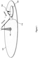
- a UE 110 is expected to have dual connectivity to both a macro cell 120 and a low-power cell 130.
- the macro cell 120 may be served by a macro eNB 140, and the low-power cell 130 may be served by a pico or femto eNB 150. While only one low-power cell 130 is shown in the figure, a plurality of low-power cells may be present within the coverage area of the macro cell 120.
- the macro cell 120 and the low-power cell 130 may be on the same frequency or different frequencies.
- the macro cell 120 may act as an anchor to provide basic radio resource control (RRC) signaling, such as mobility-related signaling and possible low- rate/high-reliability data services, while the low-power cell 130 may provide high-rate data services for traffic boosting.
- RRC radio resource control
- the current LTE systems can provide dual cell connectivity via carrier aggregation in limited deployment scenarios, such as the macro cell 120 and the low-power cell 130 being on different frequencies and from the same eNB.
- a future system may provide dual cell connectivity in additional deployment scenarios, such the macro cell 120 and the low-power cell 130 being on the same frequency or different frequencies as well as from the same eNB or different eNBs.
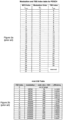
- the UE 110 may be informed of the modulation and coding scheme (MCS) of physical downlink shared channel/physical uplink shared channel (PDSCH/PUSCH) transmissions through the five-bit MCS index in a DL/UL grant.
- MCS modulation and coding scheme
- PDSCH/PUSCH physical downlink shared channel/physical uplink shared channel
- CQI channel quality index
- the five-bit MCS index for the PDSCH/PUSCH and the four-bit CQI index are defined in 3GPP Technical Specification (TS) 36.213, as shown in Figures 2a, 2b , and 2c .
- SC-FDMA single carrier frequency division multiple access
- PAPR peak-to-average power ratio
- OFDMA orthogonal frequency division multiple access
- SC-FDMA may also be referred to as discrete Fourier transform (DFT)-precoded orthogonal frequency division multiplexing (OFDM).
- DFT discrete Fourier transform
- OFDM orthogonal frequency division multiplexing
- cluster DFT-precoded OFDM With cluster DFT- precoded OFDM, a single DFT is applied to the input data stream and the DFT-precoded data are mapped to up to two non-contiguous resource block (RB) clusters.
- RB resource block
- the flexible resource allocation in clustered DFT-precoded OFDM improves the throughput performance.
- spectral efficiency may be of importance, and a low PAPR may not be a major concern due to the UE being close to the low-power cell eNB and not being power limited. Therefore, it is envisioned that a future UE may support OFDMA in the uplink in addition to SC-FDMA.
- Time division duplexing is expected to be used more often in pico cells.
- TDD Time division duplexing
- Each pico cell eNB may dynamically use subframes for either uplink or downlink to match the instantaneous traffic situation in the cell. This may lead to improvements in the end-user experience as well as the overall system throughput.
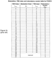
- neighboring cells dynamically configure the UUDL subframes independently, interference issues may arise, as illustrated in Figure 3 .
- two neighboring cells 310 and 320 use different TDD UUDL subframe configurations. If Cell 1 310 is in a DL subframe while Cell 2 320 is in a UL subframe, then eNB-to-eNB interference and/or UE-to-UE interference may occur.
- eNB-to-eNB interference during Cell 2's uplink signal reception, the Cell 2 eNB 340 may see interference from the downlink transmission from Cell 1's eNB 330. This interference may degrade the UE UL throughput in Cell 2 320. Furthermore, this eNB-to-eNB interference may be significant due to the possible line-of-sight between the two eNBs 330 and 340.
- UE1 350 may see interference from UE2's uplink transmission. This interference may degrade UE1's DL throughput. Furthermore, this interference may be significant if UE1 350 and UE2 360 are at cell edges with UE2 360 transmitting at a high power and UE1 350 seeing a weak signal from its eNB 330.
- CA Carrier aggregation
- component carriers (CCs) in Rel-10 are backward-compatible and can be fully accessible to Rel-8 UEs.
- Each CC appears as a separate cell with its own cell ID and transmits its own primary synchronization signal/secondary synchronization signal (PSS/SSS) and system information block (SIB) messages.
- PSS/SSS primary synchronization signal/secondary synchronization signal
- SIB system information block
- a UE can connect to one primary cell (PCell) and up to four secondary cells (SCells).
- the PCell is the cell that is initially configured during connection establishment.
- An SCell is a cell that may be configured after connection establishment, merely to provide additional radio resources.
- a single RRC connection may be established with the PCell, which controls all the CCs configured for a UE.
- RRC Radio Resource Control
- SI system information
- ACK/NACK/CSI channel state information
- cross-carrier scheduling may be supported in CA for interference coordination for the physical downlink control channel (PDCCH) in a heterogeneous network.
- One scheduler may be responsible for the scheduling of all aggregated carriers.
- the buffer status report (BSR) and scheduling request (SR) may reflect the overall buffered data for all carriers.
- Embodiments of the present disclosure address issues that may arise in the scenarios described above.
- high order modulation such as 256QAM (quadrature amplitude modulation) may be used in a pico cell to improve the spectral efficiency.
- 256QAM quadrature amplitude modulation
- OFDMA may be used in a pico cell to improve the UL spectral efficiency.
- Some of the embodiments are directed toward interference issues in a dynamic TDD system.
- Interference coordination has previously been discussed for dynamic TDD systems with slow adaptation, where the rate of TDD configuration change is greater than backhaul signaling delay, e.g., 200 milliseconds (ms).
- the interference coordination may be based on information exchanged on the X2 interface between eNBs.
- These embodiments provide interference coordination for a dynamic TDD network with fast adaptation, where the TDD configuration may change as fast as 10 ms.
- the existing CSI feedback scheme may not be sufficient to provide the channel conditions due to the dynamic UL/DL subframes from the neighboring cells.
- These embodiments may also provide improvement of CSI feedback for a dynamic TDD system.
- the macro layer may use frequency division duplexing (FDD) or TDD.
- the pico cell layer may be on a higher frequency using TDD for better traffic adaptation.
- a UE may have dual connectivity to both the macro cell and the pico cell. This is the multi-serving cell scenario, which is implemented as carrier aggregation, with the PCell being the macro FDD/TDD and an SCell being the pico cell TDD. It is also possible for the PCell to be the pico cell and for the SCell to be the macro cell.
- the current CA in LTE assumes intra- eNB carrier aggregation and aggregated carriers having the same duplex mode, i.e., either FDD or TDD.
- the embodiments provide methods to enable a UE to be served by multiple cells, which are from different eNBs (inter-eNB carrier aggregation) and with different duplex modes.
- a low-power cell may be an independent cell with its own cell ID and may be on the same carrier frequency as the macro cell or a different carrier frequency from the macro cell. Due to the spectrum availability at higher frequencies, such as 3.5 gigahertz (GHz), and to aid in interlayer interference avoidance, network operators may prefer to have the macro layer deployed at a lower frequency for large area coverage and have low- power cells deployed at a higher frequency for local area high data rate access.
- GHz gigahertz
- the low-power cell may use new carrier type (NCT), in either a standalone or non-standalone manner.
- Standalone NCT may operate on its own and may transmit the full set of control signaling.
- Non-standalone NCT means that the carrier cannot be operated on its own and the low-power cell is to be associated with the standalone carrier of the macro cell.
- the UE may obtain information regarding the low-power cell non- standalone NCT through the standalone macro carrier and in turn may be able to access the low-power cell.
- Non-standalone NCT may save control signals. For example, SIB messages and a cell-specific reference signal (CRS) may not have to be transmitted, or only part of a CRS may have to be transmitted.
- SIB messages and a cell-specific reference signal (CRS) may not have to be transmitted, or only part of a CRS may have to be transmitted.
- CRS cell-specific reference signal
- the non-standalone NCT of the low-power cell may be expected to transmit control signals that allow the UE to identify the cell ID, perform frequency and time tracking, and measure the cell.
- the macro cell may also provide the UE certain information to help reduce the control signals from the non-standalone low-power cell. For example, instead of the low-power cell transmitting PSS/SSS, the macro cell may signal the UE a list of low-power cell IDs and the UE may pin down the low-power cell ID by checking the CRS sequences.
- non-standalone NCT may be preferred for low-power cells.
- the UE may enter the network only via the macro cell if non-standalone NCT is deployed on the low- power cell. Standalone NCT may or may not be backwards compatible. Backwards compatible NCT may be less efficient as it may carry some legacy signals for legacy UEs to access.
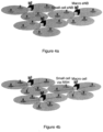
- a low-power cell is deployed as an independent eNB with its own backhaul, as shown in Figure 4a .
- the communication between the macro cell and the low-power cell involves the X2 interface with a backhaul delay.
- the low-power cell may also be deployed via a remote radio head (RRH) and may be connected to the macro cell via high-speed optical fiber, as shown in Figure 4b .
- RRH remote radio head
- the low-power cell and the macro cell may belong to the same eNB and share the same backhaul. In such a case, the communication between the macro cell and the low-power cell may be achieved with negligible delay.
- the UE may have dual connectivity to the macro cell and the low-power cell during RRC_CONNECTED mode.
- the macro cell provides only basic RRC signaling, such as paging and mobility/handover (HO) related signaling, and that all the data services go through the low-power cell.
- the macro cell may provide basic RRC signaling as well as low-rate/high-reliability data services, and the low- power cell may provide high-rate data services. For example, if a user is engaged in both a voice over internet protocol (VoIP) call and file downloading, then the VoIP call may go through the macro cell and the file downloading may go through the low-power cell.
- VoIP voice over internet protocol
- the UE may have separate RRC connections to the macro cell and to the pico cell or just one RRC connection to the macro cell. If the macro cell and the pico cell are from the same eNB (e.g., the pico cell is deployed as an RRH), then one RRC connection to the macro cell may be sufficient. If the macro cell and the pico cell are from different eNBs, then two RRC connections may be possible.
- the UE may be expected to camp on the macro cell only. Although the UE may camp on the low-power cell in the case of a standalone carrier on the low-power cell, camping on the macro cell may simplify network operation.
- the macro layer may use FDD or TDD while the low-power cell layer may be on a higher frequency using TDD for better traffic adaptation or may use FDD.
- the UE may have dual connectivity to both the macro cell and the pico cell. This multi-serving cell scenario is implemented as carrier aggregation with the PCell using macro cell FDD or TDD and the SCell using low-power cell TDD. In such cases, the UE may remain connected to the macro cell, and the low-power cell may be added or removed via SCell addition or removal.
- the UE may simultaneously communicate with the macro cell and one or more low-power cells.
- the macro layer and the low-power cell layer may be deployed with inter-band carrier aggregation, wherein the macro cell uses FDD and the low-power cell uses TDD. In such case, separate transceiver chains may be used.
- the macro cell and the low-power cell may use intra-band carrier aggregation, wherein both the macro cell and the low-power cell use TDD within the same band. In this case, for cost saving, the intra-band carrier aggregation may be implemented as a single radio frequency unit.
- discontinuous reception may be configured on a PCell due to the limited communication with the macro cell.
- different DRX configurations may be applied to a PCell and an SCell.
- the low-power cell may be informed of the subframes when the UE will communicate with the macro cell so that the data transmissions in the macro cell and the low-power cell may be coordinated to reliably maintain the two communication links under the UE maximum power constraint.
- the communication with the macro cell and the low-power cell may occupy different subframes so that the UE communicates with only one cell at any given time.
- the macro cell may determine the DRX configurations for both the macro cell and the pico cell.
- the macro cell and the low-power cell may be synchronous or asynchronous. If the macro cell and the low-power cell operate tightly, e.g., if the DRX configurations of the two cells are coordinated for UE power saving, then the transmissions from the two cells may be synchronized. That is, the subframe boundaries may be aligned. If the macro cell and the low-power cell operate independently, then the transmissions from the two cells may be asynchronous. Although the transmissions from the macro cell and the low-power cell may be synchronized, the signals arriving at the UE may not be perfectly aligned due to the different distances from the two cells to the UE.
- some of the embodiments for increasing traffic capacity in a heterogeneous deployment of low-power nodes under the coverage of an existing macro-node layer involve supporting higher order modulation.
- a UE may be in close proximity to the pico cell eNB, which may provide good channel conditions.
- higher order modulation may be used in the pico cell. That is, the highest order of modulation that can currently be used in a macro cell is 64QAM.
- a modulation order higher than 64QAM such as 256QAM
- 64QAM any modulation order higher than 64QAM may be referred to as 256QAM, but it should be understood that other higher modulation orders are possible.
- any higher order modulation format that uses more than six bits of data and can be sent over one OFDM/SC-FDM subcarrier in a single input-single out channel may be enabled because of the better channel conditions expected in a low-power cell environment.
- the existing MCS tables for PDSCH/PUSCH and the existing CQI table, shown in Figures 2a, 2b , and 2c may be modified.
- a first option is to expand the MCS and CQI index tables to include 256QAM.
- the MCS index table for the PDSCH and the CQI index table may be expanded as shown in Figures 5a and 5b .
- the modifications relative to the prior tables are illustrated by shading.
- the field modulation and coding scheme in the DL/UL grant is increased from five bits to six bits. That is, if only five bits are used for the values in column 510, then only 32 values are possible. With six bits, the expansion of the MCS table is possible.
- the CQI feedback is increased from four bits to five bits. That is, if only four bits are used for the values in column 520, then only 16 values are possible.
- the existing transport block size (TBS) tables for the PDSCH and the PUSCH in 3GPP TS 36.213 may also be modified to include the large transport block sizes for 256QAM.
- An advanced UE capable of 256QAM may assume one additional bit in the DL/UL grant decoding and one additional bit in the CQI feedback, as well as using the new MCS/CQI/TBS tables.
- the eNB may need to learn the UE's capabilities so that the eNB can transmit the DL/UL grant in the appropriate format and assume one additional bit in CQI decoding.
- the UE may indicate its relevant capability, i.e., whether 256QAM is supported, to the eNB via RRC signaling.
- certain UE categories may implicitly include such a capability, so when the UE indicates its category, its capability to support 256QAM is also indicated.
- a second option is to redesign the MCS and CQI index tables and retain five bits for the MCS indication and four bits for CQI feedback.
- the redesigned MCS/CQI index tables may have a less fine granularity of MCS/CQI.
- Figures 6a and 6b One such example is shown in Figures 6a and 6b . It can be seen in Figure 6a that only eight MCS indices use a modulation order of 2, only seven MCS indices use a modulation order of 4, and only ten MCS indices use a modulation order of 6.
- the existing TBS tables in 3GPP TS 36.213 may also be modified to include the large transport sizes for 256QAM.
- an advanced UE capable of 256QAM may use the redesigned MCS/CQI/TBS tables.
- the eNB may need to learn the UE's capabilities to determine whether the UE can use the redesigned MCS/CQI tables for DL/UL grants and CQI interpretation.
- the UE may indicate its relevant capability, i.e., whether 256QAM is supported, to the eNB via dedicated RRC signaling.
- certain UE categories may implicitly include such a capability, so when the UE indicates its category, its capability to support 256QAM is also indicated.
- the eNB may additionally or alternatively query the UE's capabilities.
- a third option is to design an additional set of MCS/CQI index tables to cover the high SNR region.
- An example of this option is shown in Figures 7a and 7b .
- the UE may use the existing MCS/CQI tables for the low to medium SNR region and may use the new MCS/CQI tables for the medium to high SNR region.
- RRC signalling may be used to indicate to the UE which set of tables to use for MCS determination and CQI feedback.
- the two sets of MCS/CQI tables may overlap (i.e., have some common entries) to ensure a smooth transition between the two configurations.
- the last nine entries of the CQI table in Figure 2b and the first nine entries of the CQI table in Figure 7b are the same.
- the eNB may need to learn the UE's capabilities to use additional MCS/CQI tables for DL/UL grants and CQI interpretation.
- the TBS tables in 3GPP TS 36.213 may also be modified to include the large transport sizes for 256QAM.
- some of the embodiments for increasing traffic capacity in a heterogeneous deployment of low-power nodes under the coverage of an existing macro-node layer involves supporting OFDMA on the UL.
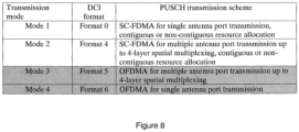
- additional PDCCH downlink control information (DCI) formats for UL grants may be introduced.
- Transmission Mode 1 is for single antenna port transmission
- Transmission Mode 2 is for multiple antenna port transmission
- PDCCH DCI format 0 is used to indicate Transmission Mode 1
- DCI format 4 is used to indicate Transmission Mode 2.
- Mode 3 and Mode 4 new transmission modes, which may be referred to as Format 5 and Format 6, may be introduced, as shown in Figure 8 .
- Shading in the figure indicates the newly introduced transmission modes and DCI formats.
- Transmission Mode 3 and DCI Format 5 are for UEs with multiple antenna ports
- Transmission Mode 4 and DCI Format 6 are for UEs with a single antenna port.
- Transmission Mode 4 and DCI Format 6 may not be included.
- the PUSCH may support up to four-layer spatial multiplexing.
- RRC signaling may be used to inform the UE about the transmission mode.
- the UE may reuse the Rel-10 UL demodulation reference signal (DMRS) which is transmitted in the middle OFDM symbol of the slot (i.e., the fourth OFDM symbol of the slot for a normal cyclic prefix (CP) and the third OFDM symbol for an extended CP) with a Zadoff-Chu sequence in the frequency domain and a possible orthogonal cover code (OCC) in the time domain.
- DMRS Rel-10 UL demodulation reference signal
- CDM code division multiplexing
- the DMRSs of different transmission layers may use different cyclic shifts of the same Zadoff-Chu base sequence.
- the same precoder for PUSCH transmission may be applied on the DMRS.
- one Zadoff-Chu sequence may be generated with a length equal to the total number of subcarriers of the non-contiguous resource blocks.
- the UE may reuse the DL UE-specific reference signal (RS) of antenna ports 7-10.
- the RS for the first and second transmission layers and the RS for third and fourth layers may be multiplexed by frequency division multiplexing (FDM).
- the RS for the first and second layers (or the third and fourth layers) may be multiplexed by means of CDM by using OCC over two consecutive resource elements in the time domain.
- the same precoder for PUSCH transmission may be applied on the RS.
- different UEs may transmit on different antenna ports with orthogonal RS sequences, or different UEs may transmit on the same antenna ports with quasi-orthogonal RS sequences generated by a different scrambling seed.
- the second option may potentially provide better channel estimation than the first option due to the RS being more distributed in the RB.
- the new DCI Formats 5 and 6 may be based on DCI Formats 4 and 0, respectively, by replacing the resource allocation field with the OFDMA resource allocation from DL grants.
- An example of DCI Format 5 is shown in Figures 9a and 9b , where the modifications compared to Format 4 are underlined.
- the references appearing in Figures 9a and 9b refer to items in 3GPP TS 36.212.
- DCI Formats 5 and 6 can allocate more than two non-contiguous resource block (RB) clusters.
- the existing DL OFDMA resource allocation type 2 may also be supported to allocate a set of contiguously allocated localized or distributed virtual resource blocks (VRBs) for UL OFDMA.
- the Rel-10 precoding codebook for SC-FDMA may be reused for UL OFDMA.
- a new codebook for UL OFDMA may also be designed. Due to the likely line-of-sight propagation environment in a pico cell, multi-layer transmission may not be efficient, and single-layer transmission with multiple antenna ports may be preferred.
- DCI Format 5 may be further simplified by, e.g., specifying only one transport block and one transmission layer so that the number of bits in the field Precoding information and number of layers in DCI may be reduced.
- a large resource block group (RBG) size may be used to reduce the number of bits in the field Resource block assignment in DCI.
- OFDMA Transmission Mode 3 OFDMA for multiple antenna port transmission
- OFDMA Mode 4 OFDMA for single antenna port transmission
- SC-FDMA Mode 1 SCFDMA for single antenna port transmission
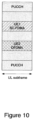
- OFDMA and SC-FDMA may be multiplexed in one UL subframe, as shown in the embodiment of Figure 10 .
- Transmission Mode 3 and 4 may also be designed to cover both SC-FDMA and OFDMA, with one bit in the DCI format to indicate whether SC-FDMA or OFDMA will be used.
- Such an embodiment may allow the UE to dynamically switch between SC-FDMA and OFDMA. Due to the small propagation delay spread in pico cells, smaller CP lengths may be introduced in L TE, for example for a better spectral efficiency. Due to the spectrum availability at high frequencies, to further enhance the data rate in pico cells, a channel bandwidth greater than 20 megahertz (MHz) may be introduced in LTE.
- MHz megahertz
- Some of the embodiments are directed toward interference coordination in a dynamic TDD network with fast adaptation, where the TDD configuration may change as fast as 10 ms. That is, with existing methods for providing TDD reconfiguration information, such as sending the reconfiguration information in a SIB message, adaptation may occur at a rate on the order of 640 ms. In some proposed methods, adaptation may occur at a much faster rate.
- a change in TDD configuration that occurs much slower than the backhaul signaling delay, for example slower than every 200 ms, may be referred to herein as slow adaptation, and a change in TDD configuration that occurs faster than the backhaul signaling delay may be referred to herein to as fast adaptation.
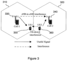
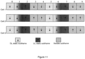
- pico cells may schedule cell-center UEs only during flexible subframes to avoid interference. That is, in one radio frame, some subframes may be static uplink or static downlink, and other subframes may have the flexibility to be either uplink or downlink for traffic adaptation. For example, if only UUDL configurations 0, 1, 2, and 6 are allowed to be used in a pico cell (i.e., configurations of 5 ms DL-to-UL switchpoint periodicity), as shown in the example of Figure 11 , the UE may assume that Subframes 0, 1, 5, and 6 are static DL subframes including special subframes, that Subframes 2 and 7 are static UL subframes, and that the remaining subframes are flexible subframes.
- all neighboring cells are on the uplink
- all neighboring cells are on the downlink.
- some cells may be on the uplink and some cells may be on the downlink.
- eNB-to-eNB interference and UE-to-UE interference may occur during the flexible subframes.
- cell-center UEs may be scheduled only during these flexible subframes.
- these embodiments may also involve having the UE feed back multiple COis for multiple sets of subframes to reflect the different interference levels in different subframes.
- the existing X2-based interference coordination scheme may not work due to the delay of X2 messages. That is, the TDD configurations of neighboring cells may not be known, as the X2-based signaling may not be fast enough to update the neighboring cell information. In this case, conservative approaches to mitigate interference may be taken.
- some subframes in a radio frame may be flexible to be either uplink or downlink for traffic adaptation while others are static uplink or static downlink.
- the UE may be signaled about the configuration of static UUDL and flexible subframes, or this information may be pre-configured.
- Each cell may receive information to determine flexible subframes and static subframes in a radio frame, e.g., from operations, administration and maintenance (OAM).
- OFAM operations, administration and maintenance
- the cell may be restricted to choose TDD configurations from a set of UUDL configurations, e.g., TDD UL/DL configurations 0, 1, 2, and 6 in current LTE, which are the configurations with 5 ms DL-to-UL switch point periodicity.
- TDD UL/DL configurations 0, 1, 2, and 6 in current LTE, which are the configurations with 5 ms DL-to-UL switch point periodicity.
- the cell in a DL subframe may reduce the transmit power by scheduling cell-center UEs to reduce the interference to a neighboring eNB which is in a UL subframe. Furthermore, during the flexible subframes, the cell in a UL subframe may schedule cell-center UEs so that the UEs will transmit at low power and their UL transmissions will not create interference to the UE's DL reception in a neighboring cell which is in a DL subframe. Such an approach virtually shrinks cell sizes in the flexible subframes to avoid interference.
- an eNB may receive signal strength reports, measurement reports, power headroom reports, or other information from a plurality of UEs and may use such information to infer the relative distances or signal attenuation factor of the UEs from the eNB.
- UEs that are determined to be relatively closer to the eNB or have smaller signal attenuation factors than other UEs may be referred to as cell-center UEs, and UEs that are determined to be relatively farther from the eNB or have larger signal attenuation factors than other UEs may be referred to as cell-edge UEs.
- the terms "cell-center” and cell-edge” are relative terms and that a UE referred to as a cell-center UE is not necessarily directly in the center of a cell and that a UE referred to as a cell-edge UE is not necessarily directly at the edge of a cell.
- the eNB uses the flexible subframes for cell-center UEs and the fixed subframes for the cell-edge as well as cell-center UEs.
- the DL transmissions in a cell scheduled in the flexible and static DL subframes obey the cell's relative narrowband transmit power (RNTP), and the UL transmissions scheduled in the flexible and static UL subframes obey the cell's high interference indicator (HII).
- the RNTP and HII may be exchanged on X2 to inform neighboring cells.
- the cell may take account of both the RNTP and the HII of a neighboring cell and attempt to schedule the transmissions such that the interference to the neighboring cell is minimized no matter whether the neighboring cell is on a UL subframe or a DL subframe.
- Cell 1 and Cell 2 be two neighboring cells with RNTP and HII values as shown in the example of Figure 12 .
- Cell 2 schedules its cell-edge UEs on RBs 26-50.
- Cell 2 schedules its cell-edge UE UL transmissions on RBs 31-50.
- Cell 1 is in a DL flexible subframe. If Cell 2 is also in a DL flexible subframe, then Cell 1 may schedule its cell-edge UEs on RBs 1-25 and its cell-center UEs on RBs 26-50. If Cell 2 is in a UL flexible subframe, Cell 1 may still schedule its high-power cell-edge UEs on RBs 1-25, as Cell 2 may schedule its cell-center UEs on the UL which are less sensitive to eNB-to-eNB interference.
- Cell 1 may schedule its cell-center UEs on RBs 26-50, as the cell-center UEs are less sensitive to UE-to-UE interference even if Cell 2 schedules its cell-edge UEs on the UL on RBs 31 to 50.
- Cell 1 which is in a DL flexible subframe, does not know whether Cell 2 is in a UL subframe or a DL subframe, it is safe for Cell 1 to schedule its cell-edge UEs on RBs 1-25 and its cell-center UEs on RBs 26-50.
- Cell 1 is in a UL flexible subframe. If Cell 2 is also in a UL flexible subframe, then Cell 1 may schedule its cell-edge UEs on RBs 1-20 and its cell-center UEs on RBs 21-50. If Cell 2 is in a DL flexible subframe, Cell 1 may still schedule its high power cell-edge UEs on RBs 1-20, as Cell 2 may schedule its cell-center UEs on the DL which are less sensitive to UE-to-UE interference.
- Cell 1 may schedule its cell-center UEs on RBs 21-50, as the cell-center UEs are less sensitive to eNB-to-eNB interference even if Cell 2 schedules high-power cell-edge UEs on the DL on RBs 26 to 50.
- Cell 1 which is in a UL flexible subframe, does not know whether Cell 2 is in a UL subframe or a DL subframe, it is safe for Cell 1 to schedule its cell-edge UEs on RBs 1-20 and its cell-center UEs on RBs 21-50.
- the cell may schedule the cell-edge UEs in the static DL/UL subframes and schedule only cell-center UEs in the flexible UUDL subframes.
- the pico cell may avoid transmitting some of the high-power common control signals, such as CRS and CSI-RS.
- CRS and CSI-RS may be coordinated and transmitted only in the static DL subframes. For instance, if the pico cell uses NCT, CRS may not have to be transmitted in every DL subframe.
- the pico cells may reduce their transmit power.
- UEs may be configured to perform radio resource management (RRM) measurements and pathloss measurement based on the high-power CRS in the static DL subframes.
- RRM radio resource management
- a new set of downlink power control parameters ⁇ A (ratio of PDSCH energy per resource element (EPRE) to CRS EPRE for OFDM symbols not containing CRS), ⁇ B (ratio of PDSCH EPRE to CRS EPRE for OFDM symbols containing CRS), and P c (ratio of PDSCH EPRE to CSI-RS EPRE) may also be defined for the flexible DL subframes and signaled to the UE.
- the power reduction of the CSI-RS or CRS during the flexible DL subframes may also be signaled to the UE so that the UE can adjust the CQI estimation for the flexible DL subframes.
- the pico cell may also let the neighboring cells know the CRS/CSI-RS configuration, such as the number of antenna ports, so that the neighboring eNB can perform interference cancellation.
- control signals may need to be transmitted at high power during the flexible subframes.
- Examples include the UL grant on the PDCCH or enhanced PDCCH (ePDCCH), which is used to schedule a future uplink transmission from a cell-edge UE, the DL ACK/NACK, which corresponds to the UL transmission from a cell-edge UE a few subframes earlier, and the ACK/NACK on the PUCCH from a cell-edge UE, which acknowledges the DL transmission a few subframes earlier.
- eNB-to-eNB interference neighboring cells that are on UL subframes may use conservative MCS levels for PUSCH transmissions.
- neighboring cells that are on DL subframes may avoid DL transmission on the band-edge RBs that are used for the PUCCH.
- one cell may be in a DL subframe while a neighboring cell may be in a special subframe, such as Subframe 6 when Cell 1 uses a TDD configuration of 5 ms DL-to-UL switch-point periodicity and Cell 2 uses a TDD configuration of 10 ms DL-to-UL switch-point periodicity.
- the cell in the DL subframe may cease transmission in the last one or two OFDM symbols so that the cell does not create interference to a neighboring cell which is in a UpPTS (Uplink Pilot Time Slot) used for the physical random access channel (PRACH) or the sounding reference signal (SRS).
- UpPTS Uplink Pilot Time Slot
- PRACH physical random access channel
- SRS sounding reference signal
- SRSs from cell-center UEs may be configured which are less sensitive to eNB-to-eNB interference.
- the interference environment may change significantly from subframe to subframe.
- Subframes 0, 1, 5, and 6 are static downlink subframes while Subframes 2 and 7 are static uplink subframes.
- the remaining Subframes 3, 4, 8, and 9 are flexible subframes which may be either DL or UL for traffic adaptation.
- the DL interference the UE sees during the flexible subframes may be different from that during the static DL subframes. This issue exists in both fast and slow adaptation of TDD configuration.
- CQI reporting may be enhanced.
- the UE may report multiple CQls for different sets of subframes, for example, per subframe CQI.
- the UE may report five CQls in the example of Figure 11 , one CQI for the static DL subframes and one CQI for each flexible subframe.
- two CQls may be fed back, one for the static DL subframes and one for the flexible subframes.
- the CQI for the flexible subframes may reflect an average of the interference levels during all of the flexible subframes. In this case, the feedback overhead reduction may be achieved at the cost of CQI accuracy.
- neighboring pico cells may exchange their TDD configurations via X2.
- an eNB may configure a reduced number of CQls for a UE with knowledge of the TDD configurations of the neighboring cells. For example, in Figure 11 , it may be assumed that a UE is in Cell 1 and that Cell 2 and Cell 3 are neighboring cells. In such an example, the eNB may only configure three CQls for the UE.
- the first CQI may correspond to the static DL subframes (Subframes 0, 1, 5, and 6).
- the second CQI may be for Subframes 3 and 8, as the UE sees the same interference from Cell 2 and Cell 3 in those two subframes.
- the third CQI may be for Subframes 4 and 9, as interference from Cell 2 and Cell 3 is the same in those two subframes.
- the resource-restricted CSI measurement introduced in Rel-10 for enhanced inter-cell interference coordination (eiCIC) almost blank subframes (ABS) may be reused for the UE to report the two CQls corresponding to static DL subframes and flexible subframes.
- the measurement resource restriction pattern for eICIC ABS is specified in the information elements (lEs) CQI-ReportConfig and MeasSubframePattern in 3GPP TS 36.331, as shown in Figure 13 . Due to the periodicity of ABS, the subframePatternTDD in the IE MeasSubframePattern is defined in terms of multiple radio frames.
- an additional subframe pattern of 10 bits may be added, which is indicated by underlining in the example of Figure 13 .
- more measurement subframe subsets may be defined in the IE CQI-ReportConfig, an example of which is shown in Figure 14 , with the additional measurement subframe subsets indicated by underlining.
- a UE in the multi-serving cell scenario, is connected to both a macro cell and a pico cell, and the macro cell and the pico cell are from different eNBs.
- the macro cell and the pico cell may be on the same frequency or different frequencies.
- the embodiments involve supporting inter-eNB carrier aggregation in the multi-serving cell scenario.
- the macro cell may be the PCell and the pico cell may be the SCell.
- PCell and SCell refer to cells on the same frequency.
- PCell and SCell are on different frequencies.
- the embodiments may further involve having a UE feed pico cell-related L1 control signals, such as ACK/NACK/CSI/SR, back to the pico cell.
- the embodiments also involve the pico cell signal the macro cell about dynamic TDD with fast adaptation.
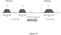
- the macro layer may use FDD or TDD while the pico cell layer may use TDD or FDD.
- the macro cell may operate on a lower carrier frequency relative to the pico cell due to the propagation characteristics. For better usage of the available bandwidth and for traffic flow adaptation, TDD is used at the pico cell.
- the macro cell may operate over ⁇ f D1 , f U1 ⁇ ⁇ ⁇ f m /2 in FDD, and the pico cell operates in TDD over ⁇ f c 2 ⁇ ⁇ ⁇ f s /2, where f D1 , f U1 and ⁇ f m are the downlink carrier frequency, the uplink carrier frequency, and the bandwidth, respectively, used by the macro cell, and f c2 and ⁇ f s are the carrier frequency and the channel bandwidth used by the pico cell using TDD.
- f c2 may preferably be higher than f D1 and f U1 .
- the LTE FDD carrier frequencies may be selected from any of the evolved universal terrestrial radio access (E-UTRA) operating bands 1-14 or 17-28 as defined in Table 5.5-1 in 3GPP TS 36.101, whereas E-UTRA operating bands 33-44 may be selected for the pico cell's TDD operation.
- the UE may have dual connectivity to the macro cell and the pico cell.
- the multi-serving cell scenario is implemented as carrier aggregation with the PCell using macro FDD and one or more SCells using pico cell TDD.
- the inter-eNB carrier aggregation may be different from the current CA, which assumes intra-eNB carrier aggregation.
- Any communication between the macro cell and the pico cell involves X2 messages and backhaul delay. At least five aspects related to such scenarios may be disclosed.
- the macro cell and the pico cell may operate more independently than the case of a pico cell being deployed via RRH. Therefore, in some embodiments, cross-carrier scheduling may not be used.
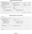
- the UL control signals of the pico cell such as the ACK/NACK/CSI corresponding to the transmissions in the pico cell, may go to the pico cell, and a bit in the RRCConnectonReconfiguration message may be used to enable this, as shown in Figures 16a and 16b .
- the macro cell and the pico cell may each have their own schedulers, as shown in the examples of Figure 17 and Figure 18 .
- information such as the subframes when the UE will communicate with the macro cell, are exchanged between the macro cell and the pico cell via X2 so that the two schedulers may coordinate the data transmissions to reliably maintain the two communication links under the UE maximum power constraint.
- the UE may report separate BSRs/SRs to reflect the buffered data on the pico cell and the macro cell.
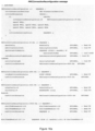
- a bit may be added in the IE RadioResourceConfigCommonSCell to notify the UE that dynamic TDD with fast adaptation is used in the pico cell. This is shown in Figure 19 .
- the static UL/DL subframes may be either pre-configured or signaled to the UE.
- different C-RNTls may be used in a macro PCell and a pico cell SCell. This may be achieved by, for example, the pico cell reserving some C-RNTIs for the macro cell to use. Alternatively, the macro cell may explicitly ask the pico cell for a C-RNTI via X2 when desired.
- the pico cell sends its system information, e.g., the TDD configuration, to the macro eNB via X2.
- the eNB may deliver the system information of the pico cell to the UE.
- the pico cell may notifies the macro cell about the actual TDD configuration via X2.
- the pico cell notifies the macro cell via X2 that dynamic TDD with fast adaptation is used in the pico cell.
- the pico cell may notify the macro eNB about the static UL/DL subframes via X2.
- the UE may scale down the transmit power to the pico cell first and prioritize the transmission to the macro cell.
- the network may avoid simultaneous transmission to the macro cell and the pico cell by letting the UE transmit all data to the pico cell. For example, in the case of a macro cell and a pico cell deployed as intra-eNB CA and the macro cell and the pico cell operating tightly (e.g., one scheduler for both), the network may route the macro cell data to the pico cell by scheduling the UE to send all data on the SCell.
- the secondary component carriers at a pico cell may be deployed as non-standalone carriers. That is, UEs may not be connected to the LTE network through the pico cell. Instead, a UE may initially connect to the LTE evolved packet core (EPC) via the macro cell and may subsequently switch to the pico cell.
- EPC LTE evolved packet core
- the aggregated system information may be broadcast by the macro cell.
- the pico cell may inform the macro cell of the relevant system information, such as the TDD configuration. In the event of updated system information, the pico cell or the macro cell may page the UEs connected to the pico cell, and/or the differential system information may be sent to those UEs in dedicated RRC signaling by the pico cell.
- the SIBs containing the pico cell SI may be transmitted less frequently.
- a new SIB message may include this information.
- the existing schemes in CA may be used to handle the SIB changes of the pico cell. For example, the SCell may first be released and then the same SCell may be added, and this may be done with a single RRC reconfiguration message. Since the network entry operation is through the macro cell, this change may not affect the network entry time.
- Some of the RRC functionality of the pico cell preferably those functions which are not delay sensitive, may be performed at the macro cell. For example, HO decision making may be done at the macro cell.
- network element 3110 includes a processor 3120 and a communications subsystem 3130, where the processor 3120 and communications subsystem 3130 cooperate to perform the methods described above.
- UE 3200 is typically a two-way wireless communication device having voice and data communication capabilities.
- UE 3200 generally has the capability to communicate with other computer systems on the Internet.
- the UE may be referred to as a data messaging device, a two-way pager, a wireless e-mail device, a cellular telephone with data messaging capabilities, a wireless Internet appliance, a wireless device, a mobile device, or a data communication device, as examples.
- UE 3200 may incorporate a communication subsystem 3211, including a receiver 3212 and a transmitter 3214, as well as associated components such as one or more antenna elements 3216 and 3218, local oscillators (LOs) 3213, and a processing module such as a digital signal processor (DSP) 3220.
- LOs local oscillators
- DSP digital signal processor
- Network access requirements will also vary depending upon the type of network 3219.
- network access is associated with a subscriber or user of UE 3200.
- a UE may require a removable user identity module (RUIM) or a subscriber identity module (SIM) card in order to operate on a network.
- the SIM/RUIM interface 3244 is normally similar to a card-slot into which a SIM/RUIM card can be inserted and ejected.
- the SIM/RUIM card can have memory and hold many key configurations 3251, and other information 3253 such as identification, and subscriber related information.
- UE 3200 may send and receive communication signals over the network 3219.
- network 3219 can consist of multiple base stations communicating with the UE.
- Signals received by antenna 3216 through communication network 3219 are input to receiver 3212, which may perform such common receiver functions as signal amplification, frequency down conversion, filtering, channel selection and the like.
- Analog to digital (A/D) conversion of a received signal allows more complex communication functions such as demodulation and decoding to be performed in the DSP 3220.
- signals to be transmitted are processed, including modulation and encoding for example, by DSP 3220 and input to transmitter 3214 for digital to analog (D/A) conversion, frequency up conversion, filtering, amplification and transmission over the communication network 3219 via antenna 3218.
- DSP 3220 not only processes communication signals, but also provides for receiver and transmitter control. For example, the gains applied to communication signals in receiver 3212 and transmitter 3214 may be adaptively controlled through automatic gain control algorithms implemented in DSP 3220.
- UE 3200 generally includes a processor 3238 which controls the overall operation of the device. Communication functions, including data and voice communications, are performed through communication subsystem 3211. Processor 3238 also interacts with further device subsystems such as the display 3222, flash memory 3224, random access memory (RAM) 3226, auxiliary input/output (I/O) subsystems 3228, serial port 3230, one or more keyboards or keypads 3232, speaker 3234, microphone 3236, other communication subsystem 3240 such as a short-range communications subsystem and any other device subsystems generally designated as 3242. Serial port 3230 could include a USB port or other port known to those in the art.
- Some of the subsystems shown in the figure perform communication-related functions, whereas other subsystems may provide "resident" or on-device functions.
- some subsystems such as keyboard 3232 and display 3222, for example, may be used for both communication-related functions, such as entering a text message for transmission over a communication network, and device-resident functions such as a calculator or task list.
- Operating system software used by the processor 3238 may be stored in a persistent store such as flash memory 3224, which may instead be a read-only memory (ROM) or similar storage element (not shown).
- ROM read-only memory
- Those skilled in the art will appreciate that the operating system, specific device applications, or parts thereof, may be temporarily loaded into a volatile memory such as RAM 3226. Received communication signals may also be stored in RAM 3226.
- flash memory 3224 can be segregated into different areas for both computer programs 3258 and program data storage 3250, 3252, 3254 and 3256. These different storage types indicate that each program can allocate a portion of flash memory 3224 for their own data storage requirements.
- Processor 3238 in addition to its operating system functions, may enable execution of software applications on the UE. A predetermined set of applications that control basic operations, including at least data and voice communication applications for example, will normally be installed on UE 3200 during manufacturing. Other applications could be installed subsequently or dynamically.
- the computer readable storage medium may be a tangible or in transitory/non-transitory medium such as optical (e.g., CD, DVD, etc.), magnetic (e.g., tape) or other memory known in the art.
- One software application may be a personal information manager (PIM) application having the ability to organize and manage data items relating to the user of the UE such as, but not limited to, e-mail, calendar events, voice mails, appointments, and task items.
- PIM personal information manager
- Such PIM application may have the ability to send and receive data items, via the wireless network 3219.
- Further applications may also be loaded onto the UE 3200 through the network 3219, an auxiliary I/O subsystem 3228, serial port 3230, short-range communications subsystem 3240 or any other suitable subsystem 3242, and installed by a user in the RAM 3226 or a non-volatile store (not shown) for execution by the processor 3238.
- Such flexibility in application installation increases the functionality of the device and may provide enhanced on-device functions, communication-related functions, or both.
- secure communication applications may enable electronic commerce functions and other such financial transactions to be performed using the UE 3200.
- a received signal such as a text message or web page download will be processed by the communication subsystem 3211 and input to the processor 3238, which may further process the received signal for output to the display 3222, or alternatively to an auxiliary I/O device 3228.
- a user of UE 3200 may also compose data items such as email messages for example, using the keyboard 3232, which may be a complete alphanumeric keyboard or telephone-type keypad, among others, in conjunction with the display 3222 and possibly an auxiliary I/O device 3228. Such composed items may then be transmitted over a communication network through the communication subsystem 3211.
- UE 3200 For voice communications, overall operation of UE 3200 is similar, except that received signals may typically be output to a speaker 3234 and signals for transmission may be generated by a microphone 3236.
- Alternative voice or audio I/O subsystems such as a voice message recording subsystem, may also be implemented on UE 3200.
- voice or audio signal output is preferably accomplished primarily through the speaker 3234, display 3222 may also be used to provide an indication of the identity of a calling party, the duration of a voice call, or other voice call related information for example.
- Serial port 3230 may normally be implemented in a personal digital assistant (PDA)-type UE for which synchronization with a user's desktop computer (not shown) may be desirable, but is an optional device component. Such a port 3230 may enable a user to set preferences through an external device or software application and may extend the capabilities of UE 3200 by providing for information or software downloads to UE 3200 other than through a wireless communication network. The alternate download path may for example be used to load an encryption key onto the device through a direct and thus reliable and trusted connection to thereby enable secure device communication. As will be appreciated by those skilled in the art, serial port 3230 can further be used to connect the UE to a computer to act as a modem.
- PDA personal digital assistant
- Other communications subsystems 3240 such as a short-range communications subsystem, is a further optional component which may provide for communication between UE 3200 and different systems or devices, which need not necessarily be similar devices.
- the subsystem 3240 may include an infrared device and associated circuits and components or a Bluetooth TM communication module to provide for communication with similarly enabled systems and devices.
- Subsystem 3240 may further include non-cellular communications such as WiFi or WiMAX.
- FIG. 22 illustrates an example of a system 3300 that includes a processing component 3310 suitable for implementing one or more embodiments disclosed herein.
- the system 3300 might include network connectivity devices 3320, random access memory (RAM) 3330, read only memory (ROM) 3340, secondary storage 3350, and input/output (I/O) devices 3360.
- RAM random access memory
- ROM read only memory
- secondary storage 3350 secondary storage
- I/O input/output
- These components might communicate with one another via a bus 3370. In some cases, some of these components may not be present or may be combined in various combinations with one another or with other components not shown.
- DSP digital signal processor
- the processor 3310 executes instructions, codes, computer programs, or scripts that it might access from the network connectivity devices 3320, RAM 3330, ROM 3340, or secondary storage 3350 (which might include various disk-based systems such as hard disk, floppy disk, or optical disk). While only one CPU 3310 is shown, multiple processors may be present. Thus, while instructions may be discussed as being executed by a processor, the instructions may be executed simultaneously, serially, or otherwise by one or multiple processors.
- the processor 3310 may be implemented as one or more CPU chips.
- the network connectivity devices 3320 may take the form of modems, modem banks, Ethernet devices, universal serial bus (USB) interface devices, serial interfaces, token ring devices, fiber distributed data interface (FDDI) devices, wireless local area network (WLAN) devices, radio transceiver devices such as code division multiple access (CDMA) devices, global system for mobile communications (GSM) radio transceiver devices, universal mobile telecommunications system (UMTS) radio transceiver devices, long term evolution (LTE) radio transceiver devices, worldwide interoperability for microwave access (WiMAX) devices, and/or other well-known devices for connecting to networks.
- CDMA code division multiple access
- GSM global system for mobile communications
- UMTS universal mobile telecommunications system
- LTE long term evolution
- WiMAX worldwide interoperability for microwave access
- These network connectivity devices 3320 may enable the processor 3310 to communicate with the Internet or one or more telecommunications networks or other networks from which the processor 3310 might receive information or to which the processor 3310 might output information.
- the network connectivity devices 3320 might also include one or more transceiver components 3325 capable of transmitting and/or receiving data wirelessly.
- the RAM 3330 might be used to store volatile data and perhaps to store instructions that are executed by the processor 3310.
- the ROM 3340 is a non-volatile memory device that typically has a smaller memory capacity than the memory capacity of the secondary storage 3350. ROM 3340 might be used to store instructions and perhaps data that are read during execution of the instructions. Access to both RAM 3330 and ROM 3340 is typically faster than to secondary storage 3350.
- the secondary storage 3350 is typically comprised of one or more disk drives or tape drives and might be used for non-volatile storage of data or as an over-flow data storage device if RAM 3330 is not large enough to hold all working data. Secondary storage 3350 may be used to store programs that are loaded into RAM 3330 when such programs are selected for execution.
- the I/O devices 3360 may include liquid crystal displays (LCDs), touch screen displays, keyboards, keypads, switches, dials, mice, track balls, voice recognizers, card readers, paper tape readers, printers, video monitors, or other well-known input/output devices.
- the transceiver 3325 might be considered to be a component of the I/O devices 3360 instead of or in addition to being a component of the network connectivity devices 3320.
Landscapes
- Engineering & Computer Science (AREA)
- Signal Processing (AREA)
- Computer Networks & Wireless Communication (AREA)
- Quality & Reliability (AREA)
- Mobile Radio Communication Systems (AREA)
Claims (10)
- Ein Verfahren zur Kommunikation in einem drahtlosen Telekommunikationsnetzwerk, wobei das Verfahren Folgendes beinhaltet:Bereitstellen, durch ein Netzwerkelement (3110) in einer ersten Zelle in dem Netzwerk, von Uplink- und Downlink-Zuteilungen in der ersten Zelle, wobei die erste Zelle eine Zelle mit niedriger Leistung innerhalb des Versorgungsbereichs einer zweiten Zelle mit hoher Leistung ist und wobei die erste Zelle als eine sekundäre Zelle und die zweite Zelle als eine primäre Zelle in einem Trägeraggregationsmodus agiert, wobei das Netzwerkelement die Uplink- und Downlink-Zuteilungen basierend auf Informationen plant, die von der zweiten Zelle über eine X2-Schnittstelle zwischen der ersten und der zweiten Zelle empfangen werden, und wobei mindestens ein Uplink-Steuersignal entweder nur von der ersten Zelle oder sowohl von der ersten Zelle als auch von der zweiten Zelle empfangen wird; undEmpfangen, durch das Netzwerkelement (3110) in der ersten Zelle, eines Pufferstatusberichts unabhängig von einem Pufferstatusbericht, der an die zweite Zelle gesendet wird;wobei, wenn dynamisches TDD mit langsamer Anpassung in der ersten Zelle verwendet wird, das Netzwerkelement die zweite Zelle über die tatsächliche TDD-Konfiguration benachrichtigt, die in der ersten Zelle verwendet wird, und wenn dynamisches TDD mit schneller Anpassung in der ersten Zelle verwendet wird, das Netzwerkelement die zweite Zelle benachrichtigt, dass dynamisches TDD mit schneller Anpassung in der ersten Zelle verwendet wird.
- Verfahren gemäß Anspruch 1, wobei die Uplink- und Downlink-Zuteilungen für Datenübertragungen sowohl in der ersten Zelle als auch in der zweiten Zelle gelten.
- Verfahren gemäß Anspruch 1, wobei das Netzwerkelement eine Planungsanforderung unabhängig von einer an die zweite Zelle gesendeten Planungsanforderung empfängt.
- Verfahren gemäß Anspruch 1, wobei dynamisches Zeitmultiplex-Duplexing, TDD, mit schneller Anpassung in der ersten Zelle verwendet wird, und wobei das Informationselement RadioResourceConfigCommonSCell in der Technischen Spezifikation, TS, 36.331 des Third Generation Partnership Project, 3GPP, modifiziert wird, um einem Benutzergerät, UE, in der ersten Zelle anzuzeigen, dass dynamisches TDD mit schneller Anpassung in der ersten Zelle verwendet wird.
- Verfahren gemäß Anspruch 1, wobei das Netzwerkelement einem Benutzergerät, UE, eine erste temporäre Zellfunknetzkennung, C-RNTI, zuweist und wobei sich die erste C-RNTI von einer zweiten C-RNTI, die dem UE die zweite Zelle zuweist, unterscheidet.
- Verfahren gemäß Anspruch 1, wobei das Netzwerkelement mindestens eine C-RNTI für die zweite Zelle reserviert, um sie mindestens einem UE zuzuweisen, das so konfiguriert ist, dass es eine duale Konnektivität mit der ersten Zelle und der zweiten Zelle aufrechterhält, und wobei das Netzwerkelement die zweite Zelle über die mindestens eine reservierte C-RNTI benachrichtigt.
- Verfahren gemäß Anspruch 1, wobei das Netzwerkelement alle Daten empfängt, die von einem UE übertragen werden, von dem das mindestens eine Uplink-Steuersignal empfangen wird, wobei das mindestens eine Uplink-Steuersignal mindestens ein Bestätigungssignal, ACK-Signal, ein negatives Bestätigungssignal, NACK-Signal, und/oder ein Kanalstatusinformationssignal, CSI-Signal, beinhaltet.
- Verfahren gemäß Anspruch 1, wobei in der ersten Zelle und in der zweiten Zelle unterschiedliche Duplex-Modi verwendet werden.
- Ein Netzwerkelement (3110) in einer Zelle in einem drahtlosen Telekommunikationsnetzwerk, wobei das Netzwerkelement Folgendes beinhaltet: einen Prozessor, der so konfiguriert ist, dass er das Verfahren gemäß einem der Ansprüche 1 bis 8 implementiert.
- Ein computerlesbares Medium, das Befehle beinhaltet, die, wenn sie von einem Prozessor eines Netzwerkelements (3110) ausgeführt werden, den Prozessor des Netzwerkelements veranlassen, das Verfahren gemäß einem der Ansprüche 1 bis 8 zu implementieren.
Applications Claiming Priority (3)
| Application Number | Priority Date | Filing Date | Title |
|---|---|---|---|
| US201261707636P | 2012-09-28 | 2012-09-28 | |
| PCT/US2013/032586 WO2014051697A1 (en) | 2012-09-28 | 2013-03-15 | Methods and apparatus for enabling further l1 enhancements in lte heterogeneous networks |
| EP13842537.6A EP2901306B1 (de) | 2012-09-28 | 2013-03-15 | Verfahren und vorrichtung zur ermöglichung weiterer l1-verbesserungen in heterogenen lte-netzwerken |
Related Parent Applications (1)
| Application Number | Title | Priority Date | Filing Date |
|---|---|---|---|
| EP13842537.6A Division EP2901306B1 (de) | 2012-09-28 | 2013-03-15 | Verfahren und vorrichtung zur ermöglichung weiterer l1-verbesserungen in heterogenen lte-netzwerken |
Publications (3)
| Publication Number | Publication Date |
|---|---|
| EP4075714A1 EP4075714A1 (de) | 2022-10-19 |
| EP4075714C0 EP4075714C0 (de) | 2024-10-16 |
| EP4075714B1 true EP4075714B1 (de) | 2024-10-16 |
Family
ID=50385096
Family Applications (4)
| Application Number | Title | Priority Date | Filing Date |
|---|---|---|---|
| EP21172533.8A Active EP3883170B1 (de) | 2012-09-28 | 2013-03-15 | Verfahren und vorrichtung zur ermöglichung von verbesserungen an flexiblen unterrahmen in heterogenen lte-netzwerken |
| EP22176999.5A Active EP4075714B1 (de) | 2012-09-28 | 2013-03-15 | Verfahren zum ermöglichen weiterer l1-verbesserungen in heterogenen lte-netzwerken |
| EP13842537.6A Active EP2901306B1 (de) | 2012-09-28 | 2013-03-15 | Verfahren und vorrichtung zur ermöglichung weiterer l1-verbesserungen in heterogenen lte-netzwerken |
| EP13842736.4A Active EP2901586B1 (de) | 2012-09-28 | 2013-03-15 | Verfahren und vorrichtung zur ermöglichung von verbesserungen an flexiblen unterrahmen in heterogenen lte-netzwerken |
Family Applications Before (1)
| Application Number | Title | Priority Date | Filing Date |
|---|---|---|---|
| EP21172533.8A Active EP3883170B1 (de) | 2012-09-28 | 2013-03-15 | Verfahren und vorrichtung zur ermöglichung von verbesserungen an flexiblen unterrahmen in heterogenen lte-netzwerken |
Family Applications After (2)
| Application Number | Title | Priority Date | Filing Date |
|---|---|---|---|
| EP13842537.6A Active EP2901306B1 (de) | 2012-09-28 | 2013-03-15 | Verfahren und vorrichtung zur ermöglichung weiterer l1-verbesserungen in heterogenen lte-netzwerken |
| EP13842736.4A Active EP2901586B1 (de) | 2012-09-28 | 2013-03-15 | Verfahren und vorrichtung zur ermöglichung von verbesserungen an flexiblen unterrahmen in heterogenen lte-netzwerken |
Country Status (5)
| Country | Link |
|---|---|
| US (5) | US9155077B2 (de) |
| EP (4) | EP3883170B1 (de) |
| CN (1) | CN104823177B (de) |
| CA (2) | CA2886214C (de) |
| WO (2) | WO2014051697A1 (de) |
Families Citing this family (125)
| Publication number | Priority date | Publication date | Assignee | Title |
|---|---|---|---|---|
| US20100316150A1 (en) * | 2009-06-05 | 2010-12-16 | Broadcom Corporation | Mixed mode operations within multiple user, multiple access, and/or MIMO wireless communications |
| US10039116B1 (en) | 2012-04-02 | 2018-07-31 | Sprint Communications Company L.P. | Long term evolution scheduler to mitigate interference |
| US9553680B1 (en) * | 2012-04-02 | 2017-01-24 | Sprint Communications Company L.P. | Uplink interference mitigation |
| WO2013172757A1 (en) * | 2012-05-15 | 2013-11-21 | Telefonaktiebolaget L M Ericsson (Publ) | Methods of sending feedback signaling under carrier specific measurement gaps in multi-carrier |
| EP2874453B1 (de) * | 2012-09-04 | 2018-10-24 | Huawei Technologies Co., Ltd. | Verfahren zur verarbeitung von kanalmessungen, basisstation und benutzervorrichtung |
| EP3883170B1 (de) | 2012-09-28 | 2022-11-30 | BlackBerry Limited | Verfahren und vorrichtung zur ermöglichung von verbesserungen an flexiblen unterrahmen in heterogenen lte-netzwerken |
| US10194423B2 (en) * | 2012-09-28 | 2019-01-29 | Lg Electronics Inc. | Uplink transmission method and uplink transmission device |
| JP2014090396A (ja) * | 2012-10-04 | 2014-05-15 | Ntt Docomo Inc | 移動局及び無線基地局 |
| DE112012007166T5 (de) * | 2012-11-22 | 2015-08-13 | Broadcom Corporation | Verfahren und Vorrichtungen für einen diskontinuierlichen Empfang |
| US9407302B2 (en) | 2012-12-03 | 2016-08-02 | Intel Corporation | Communication device, mobile terminal, method for requesting information and method for providing information |
| JP6180732B2 (ja) * | 2012-12-17 | 2017-08-16 | 株式会社Nttドコモ | ユーザ端末、無線基地局及び無線通信方法 |
| US9432168B2 (en) * | 2012-12-19 | 2016-08-30 | Lg Electronics Inc. | Method and apparatus for transmitting and receiving channel status information (CSI) for supporting 256QAM in wireless access system |
| CN103338518B (zh) * | 2012-12-31 | 2016-12-28 | 上海华为技术有限公司 | 一种发送rrc信令的方法、基站和系统 |
| EP2943030B1 (de) * | 2013-01-07 | 2017-04-19 | LG Electronics Inc. | Verfahren zum senden und empfangen eines signals auf der basis dynamischer veränderung einer drahtlosen ressourcen in einem drahtlosen kommunikationssystem und vorrichtung dafür |
| US9769842B2 (en) * | 2013-01-10 | 2017-09-19 | Telefonaktiebolgaet LM Ericsson (Publ) | Simultaneous uplink transmissions in dual connectivity mode |
| WO2014109687A1 (en) * | 2013-01-10 | 2014-07-17 | Telefonaktiebolaget L M Ericsson (Publ) | A user equipment and a method for power control of uplink transmissions |
| JP6101082B2 (ja) * | 2013-01-15 | 2017-03-22 | 株式会社Nttドコモ | 無線基地局、ユーザ端末及び無線通信方法 |
| EP2757730B1 (de) * | 2013-01-16 | 2015-11-18 | Sony Mobile Communications AB | Leistungseffiziente Steuerung der Uplink-Trägerbenutzung durch ein mobiles Endgerät |
| CN103944855B (zh) * | 2013-01-18 | 2018-08-17 | 中兴通讯股份有限公司 | 调制处理方法及装置 |
| US11177919B2 (en) * | 2013-01-18 | 2021-11-16 | Texas Instruments Incorporated | Methods for energy-efficient unicast and multicast transmission in a wireless communication system |
| US9877351B2 (en) * | 2013-01-18 | 2018-01-23 | Kyocera Corporation | Mobile communication system, user terminal, and base station |
| CN104938008B (zh) * | 2013-01-23 | 2020-07-28 | 瑞典爱立信有限公司 | 用于无线通信网络中的资源分配的方法和设备 |
| EP2950462B1 (de) * | 2013-01-25 | 2020-04-29 | LG Electronics Inc. | Verfahren und vorrichtung zur kanalmessung zwischen basisstationen in einem drahtlosen kommunikationssystem |
| US20140211647A1 (en) * | 2013-01-28 | 2014-07-31 | Innovative Sonic Corporation | Method and apparatus of small cell enhancement in a wireless communication system |
| CN103973403B (zh) * | 2013-02-06 | 2018-02-23 | 中国移动通信集团公司 | 调制编码方案指示、下行数据接收方法及装置 |
| WO2014133271A1 (ko) | 2013-02-27 | 2014-09-04 | 주식회사 케이티 | 스몰셀 환경에서 단말의 버퍼상태보고 전송 방법 및 그 장치 |
| KR20140107088A (ko) * | 2013-02-27 | 2014-09-04 | 주식회사 케이티 | 스몰셀 환경에서 단말의 버퍼상태보고 전송방법 및 장치 |
| JP5970396B2 (ja) * | 2013-03-07 | 2016-08-17 | 株式会社Nttドコモ | 無線基地局、ユーザ端末、無線通信方法及び無線通信システム |
| US9306725B2 (en) * | 2013-03-13 | 2016-04-05 | Samsung Electronics Co., Ltd. | Channel state information for adaptively configured TDD communication systems |
| US9300451B2 (en) | 2013-03-13 | 2016-03-29 | Samsung Electronics Co., Ltd. | Transmission of sounding reference signals for adaptively configured TDD communication systems |
| CN104066093B (zh) * | 2013-03-18 | 2018-03-23 | 财团法人工业技术研究院 | 无线通信系统的干扰管理方法、锚点设备、基站及其系统 |
| CN104065446A (zh) * | 2013-03-21 | 2014-09-24 | 上海贝尔股份有限公司 | 用于信令发送和接收mcs的方法 |
| WO2014146288A1 (zh) * | 2013-03-22 | 2014-09-25 | 富士通株式会社 | 信道质量指示的配置方法、调制编码方案配置方法和装置 |
| CN105122861B (zh) * | 2013-04-04 | 2020-06-16 | Lg电子株式会社 | 小规模小区中的接收方法和用户设备 |
| CN105265016A (zh) * | 2013-04-04 | 2016-01-20 | 英特尔Ip公司 | 针对支持一个上行载波的终端的双重连接 |
| US9191178B2 (en) | 2013-04-04 | 2015-11-17 | Intel IP Corporation | Enhanced node B and method for RRC connection establishment for small data transfers |
| EP2787670A1 (de) | 2013-04-05 | 2014-10-08 | Panasonic Intellectual Property Corporation of America | Tabellenanpassung eines Modulations- und Kodierungsschemas für 256-QAM |
| US9337982B2 (en) * | 2013-04-05 | 2016-05-10 | Qualcomm Incorporated | Adaptive antenna management in LTE |
| CN104105221B (zh) * | 2013-04-15 | 2019-05-21 | 中兴通讯股份有限公司 | 一种双连接的实现方法及基站 |
| US9974061B2 (en) * | 2013-04-18 | 2018-05-15 | Telefonaktiebolaget L M Ericsson (Publ) | Method, UE and base station for transmitting periodic signal/periodic system information, and method and base station for forwarding periodic system information |
| US9807656B2 (en) * | 2013-04-18 | 2017-10-31 | Telefonaktiebolaget Lm Ericsson (Publ) | Method and UE for performing random access to base station, and method and base station for establishing connection with UE |
| EP2995113B1 (de) * | 2013-05-09 | 2020-12-02 | Nokia Solutions and Networks Oy | Messungen in einem drahtlosen system |
| WO2014183083A1 (en) * | 2013-05-10 | 2014-11-13 | Huawei Technologies Co., Ltd. | Systems and methods for network adaptation support in wireless network |
| CN104219724A (zh) * | 2013-05-31 | 2014-12-17 | 中兴通讯股份有限公司 | 一种小区间协作进行干扰测量的方法和节点 |
| JP6111144B2 (ja) * | 2013-06-03 | 2017-04-05 | 株式会社Nttドコモ | 無線基地局、無線通信システム及び無線通信方法 |
| JP6125723B2 (ja) * | 2013-06-11 | 2017-05-10 | ノキア ソリューションズ アンド ネットワークス オサケユキチュア | 層構造のモビリティ |
| WO2014204102A1 (ko) * | 2013-06-17 | 2014-12-24 | 엘지전자 주식회사 | 참조 신호 전송 방법 |
| WO2015010267A1 (en) * | 2013-07-24 | 2015-01-29 | Telefonaktiebolaget L M Ericsson(Publ) | Methods and devices for cell selection |
| EP3031153B1 (de) * | 2013-08-09 | 2018-05-02 | Telefonaktiebolaget LM Ericsson (publ) | Verfahren und funkknoten zur ermöglichung der nutzung von modulation höherer ordnung in einer funkkommunikation mit einer benutzervorrichtung |
| JP6162244B2 (ja) * | 2013-08-09 | 2017-07-12 | シャープ株式会社 | 端末装置、基地局装置、および通信方法 |
| CN104378789B (zh) * | 2013-08-16 | 2019-06-07 | 索尼公司 | 无线通信系统中的通信质量确定/获取装置和方法 |
| WO2015026060A1 (ko) * | 2013-08-20 | 2015-02-26 | 엘지전자 주식회사 | 복수의 셀에 동시 접속하는 방법 및 사용자 장치 |
| JP6298164B2 (ja) * | 2013-08-29 | 2018-03-20 | エルジー エレクトロニクス インコーポレイティド | マシン通信を支援する無線アクセスシステムにおけるチャネル状態情報送信方法及び装置 |
| EP3042479B1 (de) * | 2013-09-02 | 2018-11-14 | Telefonaktiebolaget LM Ericsson (publ) | Aktivierung einer modulationsmodusauswahl |
| US20150063098A1 (en) * | 2013-09-04 | 2015-03-05 | Qualcomm Incorporated | Reducing interference from lte in unlicensed bands |
| CN104995948B (zh) * | 2013-09-18 | 2019-06-21 | 华为技术有限公司 | 数据传输方法、基站和用户设备 |
| US9078220B2 (en) * | 2013-09-27 | 2015-07-07 | Motorola Solutions, Inc. | Method and apparatus for UE power class adaption for coverage extension in LTE |
| WO2015050416A1 (ko) * | 2013-10-04 | 2015-04-09 | 엘지전자 주식회사 | 무선접속 시스템에서 256qam 지원을 위한 채널상태정보 송수신 방법 및 장치 |
| US9819471B2 (en) * | 2013-11-04 | 2017-11-14 | Texas Instruments Incorporated | Method and apparatus for configuration, measurement and reporting of channel state information for LTE TDD with dynamic UL/DL configuration |
| US9942820B2 (en) * | 2013-12-02 | 2018-04-10 | Apple Inc. | Systems and methods for cross-cell carrier aggregation for coverage balance improvement |
| US9572068B2 (en) * | 2013-12-03 | 2017-02-14 | Intel Corporation | Systems and methods for rate adaptation in full-duplex wireless communication |
| CN105850167B (zh) | 2013-12-24 | 2019-07-23 | 日本电气株式会社 | Sce所用的设备、系统和方法 |
| ES2860687T3 (es) * | 2014-01-17 | 2021-10-05 | Samsung Electronics Co Ltd | Modo de operación de conectividad dual de un equipo de usuario en una red de comunicación inalámbrica |
| EP3496471B1 (de) | 2014-01-22 | 2021-10-06 | LG Electronics Inc. | Verfahren zur leistungsregelung und benutzervorrichtung |
| KR102270662B1 (ko) * | 2014-02-11 | 2021-06-29 | 엘지전자 주식회사 | 무선으로 상향링크 전력을 제어하기 위한 방법 및 장치 |
| US9788321B2 (en) * | 2014-03-05 | 2017-10-10 | Cellos Software Ltd | Method and apparatus for resource allocation in a wireless communication network |
| KR102163635B1 (ko) * | 2014-03-21 | 2020-10-08 | 후아웨이 테크놀러지 컴퍼니 리미티드 | Tdd-fdd ca를 고려한 tpc 명령 타이밍 제어 방법 및 그 장치 |
| CN110149169B (zh) | 2014-03-21 | 2021-12-14 | 株式会社Kt | 用于发送和接收信道状态信息的方法和其设备 |
| KR20150111798A (ko) * | 2014-03-26 | 2015-10-06 | 삼성전자주식회사 | 반송파 결합을 지원하는 무선 통신 시스템에서 동기 획득 방법 및 장치 |
| KR20160144986A (ko) | 2014-04-09 | 2016-12-19 | 엘지전자 주식회사 | 전력 제어 수행 방법 및 사용자 장치 |
| CN106165515B (zh) * | 2014-04-28 | 2019-10-22 | 英特尔Ip公司 | 双连接中的同时调度请求发送 |
| WO2015167244A1 (en) * | 2014-04-29 | 2015-11-05 | Samsung Electronics Co., Ltd. | Method and apparatus for generating control information in wireless communication system |
| CN104202115B (zh) * | 2014-05-09 | 2019-05-07 | 中兴通讯股份有限公司 | 高阶编码的调制处理方法及装置、基站、终端 |
| EP3143807B1 (de) | 2014-05-16 | 2019-02-13 | Telefonaktiebolaget LM Ericsson (publ) | Bestimmung der benutzergeräteband- und synchronisationskapazität in derdualen konnektivität |
| US10230562B2 (en) | 2014-05-23 | 2019-03-12 | Lg Electronics Inc. | Method and device for supporting 256QAM in wireless access system |
| US10321335B2 (en) * | 2014-06-12 | 2019-06-11 | Lg Electronics Inc. | Method and user equipment for switching to dual connectivity in carrier aggregation |
| JP6656150B2 (ja) * | 2014-06-20 | 2020-03-04 | シャープ株式会社 | 端末装置、基地局装置、および通信方法 |
| EP3166365B1 (de) * | 2014-07-01 | 2018-06-27 | NTT DoCoMo, Inc. | Basisstation, benutzerendgerät, funkkommunikationssystem und kommunikationssteuerungsverfahren |
| WO2016021541A1 (ja) | 2014-08-06 | 2016-02-11 | 三菱電機株式会社 | 通信システム |
| US9692494B2 (en) * | 2014-08-12 | 2017-06-27 | Qualcomm Incorporated | Dynamic switching between wireless multiple access schemes |
| US10299261B2 (en) * | 2014-08-12 | 2019-05-21 | Lg Electronics Inc. | Method and device for downlink multi-user transmission in wireless communication system |
| WO2016029485A1 (zh) * | 2014-08-30 | 2016-03-03 | 华为技术有限公司 | 一种天线信息的发送、接收方法和设备 |
| US9693173B2 (en) | 2014-09-05 | 2017-06-27 | Intel Corporation | Generating, broadcasting and receiving system information blocks |
| EP3202076A1 (de) * | 2014-09-29 | 2017-08-09 | Telefonaktiebolaget LM Ericsson (publ) | Netzwerkknoten, kommunikationsvorrichtung und verfahren darin zur handhabung dynamischer unterrahmenkonfigurationen |
| US9955465B2 (en) * | 2014-10-03 | 2018-04-24 | Intel IP Corporation | Downlink control information (DCI) design for LTE devices |
| US10219292B2 (en) * | 2014-10-24 | 2019-02-26 | Qualcomm Incorporated | Flexible multiplexing and feedback for variable transmission time intervals |
| US10367551B2 (en) * | 2015-01-29 | 2019-07-30 | Intel Corporation | Precoding resource block group bundling enhancement for full dimension multi-in-multi-output |
| JP2018050089A (ja) | 2015-01-29 | 2018-03-29 | シャープ株式会社 | 端末装置、基地局装置、集積回路、および、通信方法 |
| US10244444B2 (en) | 2015-03-04 | 2019-03-26 | Qualcomm Incorporated | Dual link handover |
| US9924526B2 (en) * | 2015-03-09 | 2018-03-20 | Ofinno Technologies, Llc | Radio resource control mechanism in a wireless device and wireless network |
| JP2018093256A (ja) * | 2015-04-20 | 2018-06-14 | シャープ株式会社 | 端末装置および基地局装置 |
| US10499419B2 (en) * | 2015-05-14 | 2019-12-03 | Lg Electronics Inc. | Method for terminal for receiving PHICH in wireless communication system and terminal utilizing the method |
| US9871642B2 (en) | 2015-06-25 | 2018-01-16 | Telefonaktiebolaget Lm Ericsson (Publ) | Enabling higher-order modulation in a cellular network |
| US9660793B2 (en) | 2015-06-26 | 2017-05-23 | Intel Corporation | Leveraging full duplex for rate adaptation in wireless LANs |
| US10542469B2 (en) * | 2015-08-21 | 2020-01-21 | Samsung Electronics Co., Ltd. | Apparatus and method for supporting handover with multi-connectivity in wireless communication system |
| ES2704737T3 (es) * | 2015-08-26 | 2019-03-19 | Ericsson Telefon Ab L M | Señalización de enlace ascendente para conectividad dual |
| US10244540B2 (en) * | 2015-12-02 | 2019-03-26 | Qualcomm Incorporated | Systems and methods for mixed interference management |
| US10455558B2 (en) * | 2016-05-13 | 2019-10-22 | Qualcomm Incorporated | Handling for interruption due to carrier switching and carrier switching capability indication |
| US20170339676A1 (en) * | 2016-05-20 | 2017-11-23 | Apple Inc. | Dynamic Frame Structure for an Enhanced Cellular Network |
| US10397944B2 (en) * | 2016-07-28 | 2019-08-27 | Qualcomm Incorporated | Apparatus and method for estimating downlink channel conditions at cell-edge |
| US10187917B2 (en) * | 2016-08-22 | 2019-01-22 | Nokia Of America Corporation | Generation of mobile session identifier for neutral host network |
| TWI761368B (zh) * | 2016-09-07 | 2022-04-21 | 聯發科技股份有限公司 | 動態分時雙工設計方法及其裝置 |
| JP6779373B2 (ja) * | 2016-09-13 | 2020-11-04 | 華為技術有限公司Huawei Technologies Co.,Ltd. | 適応変調符号化方法および基地局 |
| US10887878B2 (en) | 2016-11-11 | 2021-01-05 | Sony Corporation | Wireless telecommunications apparatus and methods |
| US10499435B2 (en) * | 2017-01-05 | 2019-12-03 | Telefonaktiebolaget Lm Ericsson (Publ) | Configuration of beamforming mode |
| CN108347784B (zh) * | 2017-01-23 | 2023-10-13 | 华为技术有限公司 | 一种资源调度方法以及无线接入网设备和终端设备 |
| CN108365907B (zh) * | 2017-01-26 | 2020-12-25 | 中兴通讯股份有限公司 | 一种消除干扰的方法和装置 |
| US10958489B2 (en) * | 2017-03-21 | 2021-03-23 | Samsung Electronics Co., Ltd. | Method and apparatus for wireless communication using modulation, coding schemes, and channel quality indicators |
| EP3382915B1 (de) * | 2017-03-30 | 2021-05-05 | Rohde & Schwarz GmbH & Co. KG | Mobilkommunikationsvorrichtung, testsystem und verfahren zum testen einer zu testenden vorrichtung |
| US10904843B2 (en) * | 2017-05-15 | 2021-01-26 | Qualcomm Incorporated | Techniques and apparatuses for handling power state transitions of a beamforming apparatus |
| US10779198B1 (en) * | 2017-08-16 | 2020-09-15 | Sprint Spectrum L.P. | Adjusting handover thresholds for high power class wireless devices |
| CN109474995B (zh) * | 2017-09-08 | 2024-05-03 | 华为技术有限公司 | 一种无线通信方法及装置 |
| CN111373816B (zh) * | 2017-11-16 | 2024-04-16 | 索尼公司 | 数据发送方法、基础设施设备以及通信装置 |
| US10567108B2 (en) | 2018-02-16 | 2020-02-18 | At&T Intellectual Property I, L.P. | Adaptive configuration of modulation and coding scheme tables for new radio |
| US11477826B2 (en) * | 2018-07-16 | 2022-10-18 | Qualcomm Incorporated | High band access |
| US11057092B2 (en) | 2018-08-10 | 2021-07-06 | At&T Intellectual Property I, L.P. | Facilitating fast channel state information computation for 5G wireless communication systems |
| CN112771913A (zh) * | 2018-09-28 | 2021-05-07 | 上海诺基亚贝尔股份有限公司 | 方法、装置和计算机程序产品 |
| US11284405B2 (en) * | 2019-03-26 | 2022-03-22 | Hong Kong Applied Science and Technology Research Institute Company Limited | Method of reducing uplink inter-cell interference in a cellular communications network |
| US10757584B1 (en) * | 2019-04-23 | 2020-08-25 | Sprint Spectrum L.P. | Use of different co-existing TDD configurations on a TDD carrier, with uplink beamforming to help minimize interference |
| KR102810683B1 (ko) | 2019-05-17 | 2025-05-22 | 삼성전자 주식회사 | 무선 통신 시스템에서 지연 감소를 위한 전송 경로 결정 방법 및 장치 |
| WO2021007723A1 (en) * | 2019-07-12 | 2021-01-21 | Lenovo (Beijing) Limited | Determining uplink grants for multiple modes |
| EP4055949B1 (de) * | 2019-11-08 | 2025-12-31 | Telefonaktiebolaget Lm Ericsson (Publ) | L1-signalisierung für die anzeige des ruhezustands der zelle |
| CN111294886B (zh) * | 2020-02-10 | 2022-03-25 | 广东工业大学 | 一种基于无线能量驱动的移动边缘计算方法及装置 |
| WO2021255794A1 (ja) * | 2020-06-15 | 2021-12-23 | 日本電信電話株式会社 | 無線通信システム、無線通信システムの制御方法、無線通信システムの制御装置、及び無線通信システム制御プログラム |
| CN116530178A (zh) * | 2021-09-09 | 2023-08-01 | 上海朗帛通信技术有限公司 | 一种被用于无线通信的节点中的方法和装置 |
Family Cites Families (51)
| Publication number | Priority date | Publication date | Assignee | Title |
|---|---|---|---|---|
| GB0117071D0 (en) * | 2001-07-13 | 2001-09-05 | Koninkl Philips Electronics Nv | Hierarchical cellular radio communication system |
| US20080096557A1 (en) | 2006-10-04 | 2008-04-24 | Nokia Corporation | Efficient and dynamic identification of allocations in a wireless packet communication system |
| KR101243864B1 (ko) * | 2006-11-20 | 2013-03-25 | 한국과학기술원 | 이동통신 시스템에서 트래픽 비대칭성을 지원하기 위한하이브리드 시간 분할 듀플렉스 장치 및 방법 |
| EP2352266A4 (de) | 2008-10-29 | 2016-03-23 | Lg Electronics Inc | Verfahren zur effizienten übertragung physikalischer kanäle in einem mehrträger-aggregationszustand an ein unterstützendes breitband |
| CN102204154B (zh) | 2008-10-31 | 2014-05-21 | 诺基亚公司 | 在基于分组的无线通信系统中用于时分双工操作的子帧调度的动态分配 |
| CN101741710B (zh) | 2008-11-04 | 2011-12-07 | 电信科学技术研究院 | 一种tdd系统载波聚合的上下行配置和接收方法 |
| CN101771515A (zh) | 2008-12-30 | 2010-07-07 | 三星电子株式会社 | 传输harq-ack的方法 |
| CN101771462A (zh) | 2008-12-31 | 2010-07-07 | 华为技术有限公司 | 一种多载波系统中下行控制信道资源分配方法及设备 |
| US8521207B2 (en) | 2009-02-09 | 2013-08-27 | Qualcomm Incorporated | Closed-loop power control in multi-carrier high-speed uplink packet access |
| US20100272091A1 (en) | 2009-04-27 | 2010-10-28 | Motorola, Inc. | Uplink Scheduling Supoort in Multi-Carrier Wireless Communication Systems |
| US9565011B2 (en) * | 2009-06-04 | 2017-02-07 | Qualcomm Incorporated | Data transmission with cross-subframe control in a wireless network |
| US8942208B2 (en) * | 2009-06-22 | 2015-01-27 | Qualcomm Incorporated | Wireless communication having reduced feedback delay |
| CN101998636B (zh) * | 2009-08-14 | 2013-07-31 | 电信科学技术研究院 | 一种终端标识的使用方法、系统和设备 |
| US8737289B2 (en) | 2009-10-28 | 2014-05-27 | Lg Electronics Inc. | Method for transmitting and receiving signal of relay in radio communication system supporting multiple carriers |
| US8824968B2 (en) | 2009-12-10 | 2014-09-02 | Lg Electronics Inc. | Method and apparatus for reducing inter-cell interference in a wireless communication system |
| US8559343B2 (en) | 2009-12-23 | 2013-10-15 | Telefonaktiebolaget Lm Ericsson (Publ) | Flexible subframes |
| CN102754360B (zh) * | 2010-02-19 | 2016-10-26 | 瑞典爱立信有限公司 | 通信网络中中继节点的标识 |
| US9031010B2 (en) * | 2010-04-08 | 2015-05-12 | Qualcomm Incorporated | Separate resource partitioning management for uplink control and uplink data signals |
| US9219571B2 (en) | 2010-04-13 | 2015-12-22 | Qualcomm Incorporated | Aperiodic CQI reporting in a wireless communication network |
| US20110268045A1 (en) * | 2010-04-30 | 2011-11-03 | Youn Hyoung Heo | System and method for uplink control information transmission in carrier aggregation |
| US8861452B2 (en) * | 2010-08-16 | 2014-10-14 | Qualcomm Incorporated | Method and apparatus for use of licensed spectrum for control channels in cognitive radio communications |
| WO2012023894A1 (en) | 2010-08-20 | 2012-02-23 | Telefonaktibeolaget Lm Ericsson (Publ) | Method and node for reduced transmission activity pattern configuration |
| US9031591B2 (en) | 2010-11-17 | 2015-05-12 | Futurewei Technologies, Inc. | System and method for self-optimized inter-cell interference coordination |
| WO2012106840A1 (en) * | 2011-02-10 | 2012-08-16 | Renesas Mobile Corporation | Resource allocation for flexible tdd configuration |
| KR101859594B1 (ko) * | 2011-03-10 | 2018-06-28 | 삼성전자 주식회사 | 통신시스템에서 시분할복신 지원 방법 및 장치 |
| US9042277B2 (en) | 2011-04-11 | 2015-05-26 | Qualcomm Incorporated | Transmission of control information for FDD-TDD carrier aggregation |
| US8797924B2 (en) * | 2011-05-06 | 2014-08-05 | Innovative Sonic Corporation | Method and apparatus to improve discontinuous reception (DRX) operation for TDD (time division duplex) and FDD (frequency division duplex) mode in carrier aggregation (CA) |
| GB2486926B (en) * | 2011-06-02 | 2013-10-23 | Renesas Mobile Corp | Frequency hopping in license-exempt/shared bands |
| WO2012167431A1 (en) | 2011-06-09 | 2012-12-13 | Renesas Mobile Corporation | Interference control in time division duplex communication |
| US9137804B2 (en) * | 2011-06-21 | 2015-09-15 | Mediatek Inc. | Systems and methods for different TDD configurations in carrier aggregation |
| KR20140021676A (ko) * | 2011-06-29 | 2014-02-20 | 후지쯔 가부시끼가이샤 | 간섭층들의 표시를 위한 다운링크 제어 시그널링 |
| US10321419B2 (en) * | 2011-08-10 | 2019-06-11 | Samsung Electronics Co., Ltd. | Method and apparatus for transmitting data using a multi-carrier in a mobile communication system |
| WO2013022318A2 (ko) * | 2011-08-10 | 2013-02-14 | 삼성전자 주식회사 | 이동통신 시스템에서 복수의 캐리어를 이용해서 데이터를 전송하는 방법 및 장치 |
| AU2011375165A1 (en) | 2011-08-15 | 2014-01-16 | Cellular Communications Equipment Llc | Signaling |
| US9288823B2 (en) * | 2011-08-31 | 2016-03-15 | Nokia Technologies Oy | HARQ Timing scheme for single-carrier uplink control information with inter-site carrier aggregation |
| US11190310B2 (en) * | 2011-09-26 | 2021-11-30 | Texas Instruments Incorporated | Method and apparatus for CSI feedback in CoMP (coordinated multi-point) systems |
| US20140233439A1 (en) | 2011-10-24 | 2014-08-21 | Broadcom Corporation | Downlink-uplink configuration determination |
| WO2013104413A1 (en) * | 2012-01-10 | 2013-07-18 | Nokia Siemens Networks Oy | Providing a radio bearer on a plurality of component carriers |
| CN104126281B (zh) * | 2012-01-11 | 2018-06-15 | 诺基亚通信公司 | 用于站间载波聚合的辅小区准备的方法和装置 |
| US9237537B2 (en) * | 2012-01-25 | 2016-01-12 | Ofinno Technologies, Llc | Random access process in a multicarrier base station and wireless device |
| WO2013113390A1 (en) | 2012-02-02 | 2013-08-08 | Nokia Siemens Networks Oy | Signaling of uplink scheduling information in case of carrier aggregation |
| EP2813118A4 (de) | 2012-02-07 | 2015-09-30 | Nokia Technologies Oy | Verfahren und vorrichtung zur benachrichtigung und handhabung eines pufferstatus für eine benutzervorrichtung in einem standortübergreifenden trägeraggregationsmodus |
| CN104170484B (zh) * | 2012-03-23 | 2018-11-13 | 联发科技股份有限公司 | 解码下行链路控制信息以及反馈配置方法 |
| EP2849501B1 (de) * | 2012-05-09 | 2020-09-30 | Samsung Electronics Co., Ltd. | Verfahren und vorrichtung zur steuerung des unregelmässigen empfangs in einem mobilen kommunikationssystem |
| WO2013168917A1 (ko) * | 2012-05-09 | 2013-11-14 | 삼성전자 주식회사 | 이동통신 시스템에서 복수의 캐리어를 이용해서 데이터를 송수신하는 방법 및 장치 |
| WO2013172757A1 (en) * | 2012-05-15 | 2013-11-21 | Telefonaktiebolaget L M Ericsson (Publ) | Methods of sending feedback signaling under carrier specific measurement gaps in multi-carrier |
| US8934456B2 (en) * | 2012-05-18 | 2015-01-13 | Blackberry Limited | Method and system for connection establishment bias for wireless networks |
| KR20150023777A (ko) | 2012-06-17 | 2015-03-05 | 엘지전자 주식회사 | 무선통신 시스템에서 복수의 캐리어를 지원하는 프레임 구조에 따라 신호를 송수신하는 방법 및 이를 위한 장치 |
| AU2013300190A1 (en) * | 2012-08-07 | 2015-02-26 | Telefonaktiebolaget L M Ericsson (Publ) | Method and apparatus in a multi-carrier system for controlling interruption and measurement performance |
| EP3883170B1 (de) | 2012-09-28 | 2022-11-30 | BlackBerry Limited | Verfahren und vorrichtung zur ermöglichung von verbesserungen an flexiblen unterrahmen in heterogenen lte-netzwerken |
| EP2941834B1 (de) * | 2013-01-07 | 2018-02-21 | Samsung Electronics Co., Ltd. | Verfahren und vorrichtung für inter-enb trägeraggregation |
-
2013
- 2013-03-15 EP EP21172533.8A patent/EP3883170B1/de active Active
- 2013-03-15 EP EP22176999.5A patent/EP4075714B1/de active Active
- 2013-03-15 EP EP13842537.6A patent/EP2901306B1/de active Active
- 2013-03-15 US US13/842,550 patent/US9155077B2/en active Active
- 2013-03-15 CN CN201380062182.9A patent/CN104823177B/zh active Active
- 2013-03-15 WO PCT/US2013/032586 patent/WO2014051697A1/en not_active Ceased
- 2013-03-15 CA CA2886214A patent/CA2886214C/en active Active
- 2013-03-15 US US13/842,498 patent/US9544880B2/en active Active
- 2013-03-15 CA CA2886028A patent/CA2886028C/en active Active
- 2013-03-15 WO PCT/US2013/032590 patent/WO2014051699A1/en not_active Ceased
- 2013-03-15 EP EP13842736.4A patent/EP2901586B1/de active Active
-
2015
- 2015-10-05 US US14/875,446 patent/US9642121B2/en active Active
-
2016
- 2016-12-12 US US15/376,234 patent/US9949289B2/en active Active
-
2018
- 2018-03-13 US US15/920,184 patent/US10455612B2/en active Active
Also Published As
| Publication number | Publication date |
|---|---|
| US9155077B2 (en) | 2015-10-06 |
| EP2901306A1 (de) | 2015-08-05 |
| EP4075714C0 (de) | 2024-10-16 |
| WO2014051697A1 (en) | 2014-04-03 |
| CA2886214A1 (en) | 2014-04-03 |
| EP4075714A1 (de) | 2022-10-19 |
| US9642121B2 (en) | 2017-05-02 |
| US20170111928A1 (en) | 2017-04-20 |
| EP2901306B1 (de) | 2022-06-15 |
| CA2886028A1 (en) | 2014-04-03 |
| EP2901586A4 (de) | 2016-05-11 |
| US20140092785A1 (en) | 2014-04-03 |
| WO2014051699A1 (en) | 2014-04-03 |
| EP3883170A1 (de) | 2021-09-22 |
| CN104823177B (zh) | 2018-02-06 |
| CN104823177A (zh) | 2015-08-05 |
| US9544880B2 (en) | 2017-01-10 |
| EP2901306A4 (de) | 2016-07-06 |
| US20140092823A1 (en) | 2014-04-03 |
| US10455612B2 (en) | 2019-10-22 |
| CA2886214C (en) | 2017-10-24 |
| US20180227946A1 (en) | 2018-08-09 |
| CA2886028C (en) | 2017-09-12 |
| US20160081071A1 (en) | 2016-03-17 |
| EP3883170B1 (de) | 2022-11-30 |
| EP2901586B1 (de) | 2021-05-12 |
| EP2901586A1 (de) | 2015-08-05 |
| US9949289B2 (en) | 2018-04-17 |
Similar Documents
| Publication | Publication Date | Title |
|---|---|---|
| US10455612B2 (en) | Methods and apparatus for enabling further L1 enhancements in LTE heterogeneous networks | |
| US12549307B2 (en) | Method for configuring frequency resource about component carrier for new radio and apparatuses thereof | |
| US9712308B2 (en) | Method for enhancing small cell | |
| CN105075149B (zh) | 在多个服务小区中控制上行链路控制信息传输的方法及其装置 | |
| US10075273B2 (en) | Method and system having reference signal design for new carrier types | |
| US9167451B2 (en) | Method and apparatus for measuring interference in wireless communication system | |
| JP2020080564A (ja) | 送信制御実行方法及びユーザ装置 | |
| US9585110B2 (en) | Method for transmitting and receiving uplink signals, and apparatus therefor | |
| US9787451B2 (en) | Method and apparatus for transmitting a sounding reference signal by a terminal | |
| Al-Shibly et al. | Carrier aggregation in long term evolution-advanced | |
| JP2016534658A (ja) | 無線通信システムにおける上向きリンク電力を制御する方法及び装置 | |
| JP2015534326A (ja) | 無線通信システムにおいて下りリンク制御信号を受信又は送信するための方法及びそのための装置 | |
| KR102281357B1 (ko) | 비주기적 사운딩 참조신호의 전송방법 및 수신방법, 그 단말, 그 기지국 | |
| KR20130078137A (ko) | 무선 통신 시스템에서 제어정보의 전송 장치 및 방법 |
Legal Events
| Date | Code | Title | Description |
|---|---|---|---|
| PUAI | Public reference made under article 153(3) epc to a published international application that has entered the european phase |
Free format text: ORIGINAL CODE: 0009012 |
|
| STAA | Information on the status of an ep patent application or granted ep patent |
Free format text: STATUS: THE APPLICATION HAS BEEN PUBLISHED |
|
| AC | Divisional application: reference to earlier application |
Ref document number: 2901306 Country of ref document: EP Kind code of ref document: P |
|
| AK | Designated contracting states |
Kind code of ref document: A1 Designated state(s): AL AT BE BG CH CY CZ DE DK EE ES FI FR GB GR HR HU IE IS IT LI LT LU LV MC MK MT NL NO PL PT RO RS SE SI SK SM TR |
|
| STAA | Information on the status of an ep patent application or granted ep patent |
Free format text: STATUS: REQUEST FOR EXAMINATION WAS MADE |
|
| 17P | Request for examination filed |
Effective date: 20230320 |
|
| RBV | Designated contracting states (corrected) |
Designated state(s): AL AT BE BG CH CY CZ DE DK EE ES FI FR GB GR HR HU IE IS IT LI LT LU LV MC MK MT NL NO PL PT RO RS SE SI SK SM TR |
|
| GRAP | Despatch of communication of intention to grant a patent |
Free format text: ORIGINAL CODE: EPIDOSNIGR1 |
|
| STAA | Information on the status of an ep patent application or granted ep patent |
Free format text: STATUS: GRANT OF PATENT IS INTENDED |
|
| INTG | Intention to grant announced |
Effective date: 20240510 |
|
| GRAS | Grant fee paid |
Free format text: ORIGINAL CODE: EPIDOSNIGR3 |
|
| GRAA | (expected) grant |
Free format text: ORIGINAL CODE: 0009210 |
|
| STAA | Information on the status of an ep patent application or granted ep patent |
Free format text: STATUS: THE PATENT HAS BEEN GRANTED |
|
| RAP1 | Party data changed (applicant data changed or rights of an application transferred) |
Owner name: MALIKIE INNOVATIONS LIMITED |
|
| AC | Divisional application: reference to earlier application |
Ref document number: 2901306 Country of ref document: EP Kind code of ref document: P |
|
| AK | Designated contracting states |
Kind code of ref document: B1 Designated state(s): AL AT BE BG CH CY CZ DE DK EE ES FI FR GB GR HR HU IE IS IT LI LT LU LV MC MK MT NL NO PL PT RO RS SE SI SK SM TR |
|
| REG | Reference to a national code |
Ref country code: GB Ref legal event code: FG4D |
|
| REG | Reference to a national code |
Ref country code: DE Ref legal event code: R096 Ref document number: 602013086213 Country of ref document: DE Ref country code: CH Ref legal event code: EP |
|
| REG | Reference to a national code |
Ref country code: IE Ref legal event code: FG4D |
|
| U01 | Request for unitary effect filed |
Effective date: 20241111 |
|
| U07 | Unitary effect registered |
Designated state(s): AT BE BG DE DK EE FI FR IT LT LU LV MT NL PT RO SE SI Effective date: 20241119 |
|
| PG25 | Lapsed in a contracting state [announced via postgrant information from national office to epo] |
Ref country code: IS Free format text: LAPSE BECAUSE OF FAILURE TO SUBMIT A TRANSLATION OF THE DESCRIPTION OR TO PAY THE FEE WITHIN THE PRESCRIBED TIME-LIMIT Effective date: 20250216 Ref country code: HR Free format text: LAPSE BECAUSE OF FAILURE TO SUBMIT A TRANSLATION OF THE DESCRIPTION OR TO PAY THE FEE WITHIN THE PRESCRIBED TIME-LIMIT Effective date: 20241016 |
|
| PG25 | Lapsed in a contracting state [announced via postgrant information from national office to epo] |
Ref country code: ES Free format text: LAPSE BECAUSE OF FAILURE TO SUBMIT A TRANSLATION OF THE DESCRIPTION OR TO PAY THE FEE WITHIN THE PRESCRIBED TIME-LIMIT Effective date: 20241016 |
|
| PG25 | Lapsed in a contracting state [announced via postgrant information from national office to epo] |
Ref country code: NO Free format text: LAPSE BECAUSE OF FAILURE TO SUBMIT A TRANSLATION OF THE DESCRIPTION OR TO PAY THE FEE WITHIN THE PRESCRIBED TIME-LIMIT Effective date: 20250116 |
|
| PG25 | Lapsed in a contracting state [announced via postgrant information from national office to epo] |
Ref country code: GR Free format text: LAPSE BECAUSE OF FAILURE TO SUBMIT A TRANSLATION OF THE DESCRIPTION OR TO PAY THE FEE WITHIN THE PRESCRIBED TIME-LIMIT Effective date: 20250117 |
|
| PG25 | Lapsed in a contracting state [announced via postgrant information from national office to epo] |
Ref country code: PL Free format text: LAPSE BECAUSE OF FAILURE TO SUBMIT A TRANSLATION OF THE DESCRIPTION OR TO PAY THE FEE WITHIN THE PRESCRIBED TIME-LIMIT Effective date: 20241016 |
|
| PGFP | Annual fee paid to national office [announced via postgrant information from national office to epo] |
Ref country code: GB Payment date: 20250325 Year of fee payment: 13 |
|
| PG25 | Lapsed in a contracting state [announced via postgrant information from national office to epo] |
Ref country code: RS Free format text: LAPSE BECAUSE OF FAILURE TO SUBMIT A TRANSLATION OF THE DESCRIPTION OR TO PAY THE FEE WITHIN THE PRESCRIBED TIME-LIMIT Effective date: 20250116 |
|
| U20 | Renewal fee for the european patent with unitary effect paid |
Year of fee payment: 13 Effective date: 20250325 |
|
| PG25 | Lapsed in a contracting state [announced via postgrant information from national office to epo] |
Ref country code: SM Free format text: LAPSE BECAUSE OF FAILURE TO SUBMIT A TRANSLATION OF THE DESCRIPTION OR TO PAY THE FEE WITHIN THE PRESCRIBED TIME-LIMIT Effective date: 20241016 |
|
| PG25 | Lapsed in a contracting state [announced via postgrant information from national office to epo] |
Ref country code: SK Free format text: LAPSE BECAUSE OF FAILURE TO SUBMIT A TRANSLATION OF THE DESCRIPTION OR TO PAY THE FEE WITHIN THE PRESCRIBED TIME-LIMIT Effective date: 20241016 |
|
| PG25 | Lapsed in a contracting state [announced via postgrant information from national office to epo] |
Ref country code: CZ Free format text: LAPSE BECAUSE OF FAILURE TO SUBMIT A TRANSLATION OF THE DESCRIPTION OR TO PAY THE FEE WITHIN THE PRESCRIBED TIME-LIMIT Effective date: 20241016 |
|
| PLBE | No opposition filed within time limit |
Free format text: ORIGINAL CODE: 0009261 |
|
| STAA | Information on the status of an ep patent application or granted ep patent |
Free format text: STATUS: NO OPPOSITION FILED WITHIN TIME LIMIT |
|
| 26N | No opposition filed |
Effective date: 20250717 |
|
| PG25 | Lapsed in a contracting state [announced via postgrant information from national office to epo] |
Ref country code: MC Free format text: LAPSE BECAUSE OF FAILURE TO SUBMIT A TRANSLATION OF THE DESCRIPTION OR TO PAY THE FEE WITHIN THE PRESCRIBED TIME-LIMIT Effective date: 20241016 |
|
| REG | Reference to a national code |
Ref country code: CH Ref legal event code: H13 Free format text: ST27 STATUS EVENT CODE: U-0-0-H10-H13 (AS PROVIDED BY THE NATIONAL OFFICE) Effective date: 20251023 |
|
| PG25 | Lapsed in a contracting state [announced via postgrant information from national office to epo] |
Ref country code: CH Free format text: LAPSE BECAUSE OF NON-PAYMENT OF DUE FEES Effective date: 20250331 |
|
| PG25 | Lapsed in a contracting state [announced via postgrant information from national office to epo] |
Ref country code: IE Free format text: LAPSE BECAUSE OF NON-PAYMENT OF DUE FEES Effective date: 20250315 |