EP4075698B1 - Verfahren zur bestimmung des empfangszustands von datenrahmen und kommunikationsvorrichtung - Google Patents
Verfahren zur bestimmung des empfangszustands von datenrahmen und kommunikationsvorrichtung Download PDFInfo
- Publication number
- EP4075698B1 EP4075698B1 EP21738392.6A EP21738392A EP4075698B1 EP 4075698 B1 EP4075698 B1 EP 4075698B1 EP 21738392 A EP21738392 A EP 21738392A EP 4075698 B1 EP4075698 B1 EP 4075698B1
- Authority
- EP
- European Patent Office
- Prior art keywords
- link
- frame
- link device
- data frame
- time
- Prior art date
- Legal status (The legal status is an assumption and is not a legal conclusion. Google has not performed a legal analysis and makes no representation as to the accuracy of the status listed.)
- Active
Links
Images


Classifications
-
- H—ELECTRICITY
- H04—ELECTRIC COMMUNICATION TECHNIQUE
- H04L—TRANSMISSION OF DIGITAL INFORMATION, e.g. TELEGRAPHIC COMMUNICATION
- H04L1/00—Arrangements for detecting or preventing errors in the information received
- H04L1/12—Arrangements for detecting or preventing errors in the information received by using return channel
- H04L1/16—Arrangements for detecting or preventing errors in the information received by using return channel in which the return channel carries supervisory signals, e.g. repetition request signals
- H04L1/1607—Details of the supervisory signal
- H04L1/1621—Group acknowledgement, i.e. the acknowledgement message defining a range of identifiers, e.g. of sequence numbers
-
- H—ELECTRICITY
- H04—ELECTRIC COMMUNICATION TECHNIQUE
- H04L—TRANSMISSION OF DIGITAL INFORMATION, e.g. TELEGRAPHIC COMMUNICATION
- H04L1/00—Arrangements for detecting or preventing errors in the information received
- H04L1/12—Arrangements for detecting or preventing errors in the information received by using return channel
- H04L1/16—Arrangements for detecting or preventing errors in the information received by using return channel in which the return channel carries supervisory signals, e.g. repetition request signals
- H04L1/18—Automatic repetition systems, e.g. Van Duuren systems
- H04L1/1829—Arrangements specially adapted for the receiver end
- H04L1/1858—Transmission or retransmission of more than one copy of acknowledgement message
-
- H—ELECTRICITY
- H04—ELECTRIC COMMUNICATION TECHNIQUE
- H04L—TRANSMISSION OF DIGITAL INFORMATION, e.g. TELEGRAPHIC COMMUNICATION
- H04L1/00—Arrangements for detecting or preventing errors in the information received
- H04L1/0001—Systems modifying transmission characteristics according to link quality, e.g. power backoff
- H04L1/0006—Systems modifying transmission characteristics according to link quality, e.g. power backoff by adapting the transmission format
- H04L1/0007—Systems modifying transmission characteristics according to link quality, e.g. power backoff by adapting the transmission format by modifying the frame length
- H04L1/0008—Systems modifying transmission characteristics according to link quality, e.g. power backoff by adapting the transmission format by modifying the frame length by supplementing frame payload, e.g. with padding bits
-
- H—ELECTRICITY
- H04—ELECTRIC COMMUNICATION TECHNIQUE
- H04L—TRANSMISSION OF DIGITAL INFORMATION, e.g. TELEGRAPHIC COMMUNICATION
- H04L1/00—Arrangements for detecting or preventing errors in the information received
- H04L1/08—Arrangements for detecting or preventing errors in the information received by repeating transmission, e.g. Verdan system
-
- H—ELECTRICITY
- H04—ELECTRIC COMMUNICATION TECHNIQUE
- H04L—TRANSMISSION OF DIGITAL INFORMATION, e.g. TELEGRAPHIC COMMUNICATION
- H04L1/00—Arrangements for detecting or preventing errors in the information received
- H04L1/12—Arrangements for detecting or preventing errors in the information received by using return channel
- H04L1/16—Arrangements for detecting or preventing errors in the information received by using return channel in which the return channel carries supervisory signals, e.g. repetition request signals
- H04L1/1607—Details of the supervisory signal
- H04L1/1614—Details of the supervisory signal using bitmaps
-
- H—ELECTRICITY
- H04—ELECTRIC COMMUNICATION TECHNIQUE
- H04L—TRANSMISSION OF DIGITAL INFORMATION, e.g. TELEGRAPHIC COMMUNICATION
- H04L1/00—Arrangements for detecting or preventing errors in the information received
- H04L1/12—Arrangements for detecting or preventing errors in the information received by using return channel
- H04L1/16—Arrangements for detecting or preventing errors in the information received by using return channel in which the return channel carries supervisory signals, e.g. repetition request signals
- H04L1/1607—Details of the supervisory signal
- H04L1/1628—List acknowledgements, i.e. the acknowledgement message consisting of a list of identifiers, e.g. of sequence numbers
-
- H—ELECTRICITY
- H04—ELECTRIC COMMUNICATION TECHNIQUE
- H04L—TRANSMISSION OF DIGITAL INFORMATION, e.g. TELEGRAPHIC COMMUNICATION
- H04L1/00—Arrangements for detecting or preventing errors in the information received
- H04L1/12—Arrangements for detecting or preventing errors in the information received by using return channel
- H04L1/16—Arrangements for detecting or preventing errors in the information received by using return channel in which the return channel carries supervisory signals, e.g. repetition request signals
- H04L1/1607—Details of the supervisory signal
- H04L1/1635—Cumulative acknowledgement, i.e. the acknowledgement message applying to all previous messages
-
- H—ELECTRICITY
- H04—ELECTRIC COMMUNICATION TECHNIQUE
- H04L—TRANSMISSION OF DIGITAL INFORMATION, e.g. TELEGRAPHIC COMMUNICATION
- H04L1/00—Arrangements for detecting or preventing errors in the information received
- H04L1/12—Arrangements for detecting or preventing errors in the information received by using return channel
- H04L1/16—Arrangements for detecting or preventing errors in the information received by using return channel in which the return channel carries supervisory signals, e.g. repetition request signals
- H04L1/1607—Details of the supervisory signal
- H04L1/1685—Details of the supervisory signal the supervisory signal being transmitted in response to a specific request, e.g. to a polling signal
-
- H—ELECTRICITY
- H04—ELECTRIC COMMUNICATION TECHNIQUE
- H04L—TRANSMISSION OF DIGITAL INFORMATION, e.g. TELEGRAPHIC COMMUNICATION
- H04L1/00—Arrangements for detecting or preventing errors in the information received
- H04L1/12—Arrangements for detecting or preventing errors in the information received by using return channel
- H04L1/16—Arrangements for detecting or preventing errors in the information received by using return channel in which the return channel carries supervisory signals, e.g. repetition request signals
- H04L1/18—Automatic repetition systems, e.g. Van Duuren systems
- H04L1/1829—Arrangements specially adapted for the receiver end
- H04L1/1864—ARQ related signaling
-
- H—ELECTRICITY
- H04—ELECTRIC COMMUNICATION TECHNIQUE
- H04L—TRANSMISSION OF DIGITAL INFORMATION, e.g. TELEGRAPHIC COMMUNICATION
- H04L1/00—Arrangements for detecting or preventing errors in the information received
- H04L1/12—Arrangements for detecting or preventing errors in the information received by using return channel
- H04L1/16—Arrangements for detecting or preventing errors in the information received by using return channel in which the return channel carries supervisory signals, e.g. repetition request signals
- H04L1/18—Automatic repetition systems, e.g. Van Duuren systems
- H04L1/1867—Arrangements specially adapted for the transmitter end
- H04L1/188—Time-out mechanisms
-
- H—ELECTRICITY
- H04—ELECTRIC COMMUNICATION TECHNIQUE
- H04L—TRANSMISSION OF DIGITAL INFORMATION, e.g. TELEGRAPHIC COMMUNICATION
- H04L69/00—Network arrangements, protocols or services independent of the application payload and not provided for in the other groups of this subclass
- H04L69/14—Multichannel or multilink protocols
-
- H—ELECTRICITY
- H04—ELECTRIC COMMUNICATION TECHNIQUE
- H04L—TRANSMISSION OF DIGITAL INFORMATION, e.g. TELEGRAPHIC COMMUNICATION
- H04L69/00—Network arrangements, protocols or services independent of the application payload and not provided for in the other groups of this subclass
- H04L69/30—Definitions, standards or architectural aspects of layered protocol stacks
- H04L69/32—Architecture of open systems interconnection [OSI] 7-layer type protocol stacks, e.g. the interfaces between the data link level and the physical level
- H04L69/322—Intralayer communication protocols among peer entities or protocol data unit [PDU] definitions
- H04L69/324—Intralayer communication protocols among peer entities or protocol data unit [PDU] definitions in the data link layer [OSI layer 2], e.g. HDLC
-
- H—ELECTRICITY
- H04—ELECTRIC COMMUNICATION TECHNIQUE
- H04W—WIRELESS COMMUNICATION NETWORKS
- H04W84/00—Network topologies
- H04W84/02—Hierarchically pre-organised networks, e.g. paging networks, cellular networks, WLAN [Wireless Local Area Network] or WLL [Wireless Local Loop]
- H04W84/10—Small scale networks; Flat hierarchical networks
- H04W84/12—WLAN [Wireless Local Area Networks]
-
- H—ELECTRICITY
- H04—ELECTRIC COMMUNICATION TECHNIQUE
- H04L—TRANSMISSION OF DIGITAL INFORMATION, e.g. TELEGRAPHIC COMMUNICATION
- H04L1/00—Arrangements for detecting or preventing errors in the information received
- H04L1/0078—Avoidance of errors by organising the transmitted data in a format specifically designed to deal with errors, e.g. location
- H04L1/0083—Formatting with frames or packets; Protocol or part of protocol for error control
-
- H—ELECTRICITY
- H04—ELECTRIC COMMUNICATION TECHNIQUE
- H04L—TRANSMISSION OF DIGITAL INFORMATION, e.g. TELEGRAPHIC COMMUNICATION
- H04L1/00—Arrangements for detecting or preventing errors in the information received
- H04L2001/0092—Error control systems characterised by the topology of the transmission link
- H04L2001/0093—Point-to-multipoint
Definitions
- the present invention relates to the communication field, and in particular, to a method for determining a receiving status of a data frame and a communication apparatus.
- wireless devices support multi-band communication. For example, communication is performed on 2.4 GHz, 5 GHz, and 60 GHz frequency bands at the same time, or communication is performed on different channels of a same frequency band (or different frequency bands) at the same time, to increase a communication rate between devices.
- Such devices are usually referred to as multi-band devices, or multi-link devices, and sometimes are alternatively referred to as multi-link entities or multi-band entities.
- the following uses the multi-link device as an example for description.
- the multi-link device usually includes multiple stations (stations, STAs), and each station works on a specific frequency band or channel.
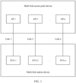
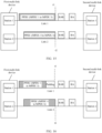
- the multi-link device may be an access point device, or a station device. If the multi-link device is an access point device, the multi-link device includes one or more access points (access points, APs). If the multi-link device is a station device, the multi-link device includes one or more non-access point stations (non-access point stations, non-AP STAs). For example, as shown in FIG. 1 , a multi-link access point device includes an AP 1 to an AP n, and a multi-link station device include a STA 1 to a STA n.
- the multi-link access point device can determine, based on the BA frame, only a receiving status of a data frame transmitted over the link, and may not accurately determine the receiving status of the data frame transmitted over the another link.
- the document IEEE DRAFT, vol.802.11 EHT; 80211be, January 10, 2020 refers to a multi-link block ACK architecture.
- the document IEEE DRAFT, vol. 802.11 EHT; 802.11be, January 9, 2020 refers to A-MPDU and block acknowledgement, BA, issues.
- this application provides a method for determining a receiving status of a data frame according to independent claim 1.
- Multiple means two or more than two.
- “And/or” describes an association relationship for describing associated objects and represents that three relationships may exist. For example, A and/or B may represent the following three cases: Only A exists, both A and B exist, and only B exists. The character “/” generally indicates an "or” relationship between the associated objects.
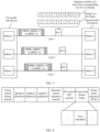
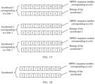
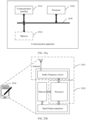
- FIG. 2 is a schematic diagram of a system architecture according to an embodiment of this application.
- the system architecture includes a first multi-link device and a second multi-link device.
- the first multi-link device is an access point (access point, AP)
- the second multi-link device is a non-access point station (non-access point station, non-AP STA).
- the first multi-link device is a non-AP STA
- the second multi-link device is an AP.
- both the first multi-link device and the second multi-link device are non-AP STAs.
- the first multi-link device includes multiple stations
- the second multi-link device includes multiple stations.
- Each station in the first multi-link device or the second multi-link device works on a specific frequency band or channel.
- the multiple stations in the first multi-link device may be located in different geographical locations, or the multiple stations are located in a same physical device.
- the multiple stations in the second multi-link device may be located in different geographical locations, or the multiple stations are located in a same physical device.
- a link between a station 2 in the first multi-link device and a station 2 in the second multi-link device is a link 2.
- a link between a station 3 in the first multi-link device and a station 3 in the second multi-link device is a link 3.
- An example in which there are three links between the first multi-link device and the second multi-link device in FIG. 2 is used for description. Certainly, there may alternatively be two or more than three links between the first multi-link device and the second multi-link device.
- the AP may be a device that supports the 802.11be standard.
- the AP may alternatively be a device that supports multiple current and future wireless local area network (wireless local area network, WLAN) 802.11 family standards, such as 802.11ax, 802.11ac, 802.11n, 802.11g, 802.11b, and 802.11a.
- WLAN wireless local area network
- the non-AP STA may also support multiple current and future wireless local area network (wireless local area network, WLAN) standards of the 802.11 family standards, such as 802.11ax, 802.11ac, 802.11n, 802.11g, 802.11b, and 802.11a.
- WLAN wireless local area network
- the AP and the non-AP STA may be devices applied to an Internet of Vehicles, Internet of Things nodes, sensors, or the like in an Internet of Things (Internet of Things, IoT), smart cameras, smart remote controls, smart water or electricity meters, or the like in a smart home, or sensors in a smart city.
- IoT Internet of Things
- smart cameras smart remote controls
- smart water or electricity meters smart water or electricity meters, or the like in a smart home, or sensors in a smart city.
- the first multi-link device may send data frames to the second multi-link device over multiple links.
- the data frame may be a media access control (Media Access Control, MAC) protocol data unit (MAC protocol data unit, MPDU).
- MAC Media Access Control
- MPDU media access control protocol data unit
- the second multi-link device needs to feed back a receiving status of the data frame to the first multi-link device by using a BA frame.
- the receiving status may be a receiving success or receiving failure.
- the receiving status may also be referred to as an acknowledgment status.
- the first multi-link device determines, based on the receiving status of the data frame, whether to retransmit the data frame to the second multi-link device.
- the second multi-link device may include, in a BA frame sent over a link, receiving statuses of data frames transmitted over the link and another link.
- the BA frame may be referred to as a multi-link BA frame.
- the first multi-link device may not accurately determine, based on the multi-link BA frame, receiving statuses of data frames transmitted over some links.
- the first multi-link device may determine a receiving status of a data frame that has been successfully received by the second multi-link device as receiving failure. This causes unnecessary retransmission of the data frame.
- the following uses a specific example to describe a reason why the first multi-link device cannot accurately determine, based on the multi-link BA frame, the receiving statuses of the data frames transmitted over some links.
- the data frame is an MPDU.
- the first multi-link device sends an MPDU 1 to an MPDU 3 to the second multi-link device over the link 1, sends an MPDU 4 to an MPDU 6 to the second multi-link device over the link 2, and sends an MPDU 7 to an MPDU 9 to the second multi-link device over the link 3.
- the station 1 of the first multi-link device may aggregate the MPDU 1 to the MPDU 3 into an A-MPDU, include the A-MPDU in a PPDU, and send the PPDU to the station 1 of the second multi-link device.
- the station 2 of the first multi-link device may aggregate the MPDU 4 to the MPDU 6 into an A-MPDU, include the A-MPDU in a PPDU, and send the PPDU to the station 2 of the second multi-link device.
- the station 3 of the first multi-link device may aggregate the MPDU 7 to the MPDU 9 into an A-MPDU, include the A-MPDU in a PPDU, and send the PPDU to the station 3 of the second multi-link device.
- the second multi-link device sends a BA frame to the first multi-link device over the link 1, where the BAframe carries a bitmap.
- the bitmap includes nine bits, and bit values of the nine bits are 111111110.
- a 1 st bit is corresponding to the MPDU 1
- a 2 nd bit is corresponding to the MPDU 2
- a 9 th bit is corresponding to the MPDU 9.
- the station 1 corresponding to the link 1 in the second multi-link device sets a bit value corresponding to a correctly received MPDU to 1, and sets bit values corresponding to remaining MPDUs to 0.
- the first multi-link device determines that the MPDU corresponding to the bit value 1 is successfully received, but cannot accurately determine a receiving status of the MPDU 9 corresponding to a bit value 0.
- a bit whose value is 0 has ambiguity.
- the station 1 in the second multi-link device needs to generate the BA frame that includes receiving statuses of MPDUs of multiple links. After receiving MPDUs, the station 2 and the station 3 in the second multi-link device need to transfer receiving statuses of the MPDUs to the station 1 in the second multi-link device, so that the station 1 in the second multi-link device generates a BA frame including receiving statuses of MPDUs transmitted over the link 1 to the link 3. Due to a transmission delay, when the station 1 in the second multi-link device generates the BA frame, although the station 2 in the second multi-link device has successfully received the MPDU 9, the station 2 may have not yet transferred the receiving status of the MPDU 9 to the station 1 in the second multi-link device.
- the station 1 in the second multi-link device sets the bit value corresponding to the MPDU 9 to 0.
- a delay problem is especially obvious in a non-collocated scenario.
- the second multi-link device is a logical device, and the station 1 and the station 2 in the second multi-link device are located in different geographical locations and different physical devices.
- the station 1 and the station 2 in the second multi-link device may be connected through a wired cable or in another manner (a specific wireless technology).
- the second multi-link device sets the bit corresponding to the MPDU 9 to 0.
- the MPDU 9 fails to be received.
- the station 2 of the second multi-link device does not send the receiving status of the MPDU 9 to the station 1 of the second multi-link device in time. Therefore, when the bit value corresponding to the MPDU 9 is 0, ambiguity exists. In one case, it indicates that the receiving status of the MPDU 9 is receiving failure. In the other case, it indicates that the receiving status of the MPDU 9 is not carried. The first multi-link device cannot accurately determine whether the receiving status of the MPDU 9 is the receiving failure or the station 2 of the second multi-link device does not send the receiving status of the MPDU 9 to the station 1 of the second multi-link device in time.
- embodiments of this application provide a method for determining a receiving status of a data frame and a first multi-link device. The following further describes the method for determining a receiving status of a data frame and the first multi-link device that are provided in this application.
- FIG. 4 is a schematic flowchart of a method for determining a receiving status of a data frame according to an embodiment of this application.
- the method for determining a receiving status of a data frame includes the following step 401 to step 403.
- the method shown in FIG. 4 may be performed by a first multi-link device and a second multi-link device.
- the method shown in FIG. 4 may be executed by a chip in the first multi-link device and a chip in the second multi-link device.
- FIG. 4 is described by using an example in which the first multi-link device and the second multi-link device are used as execution bodies.
- At least two stations in the first multi-link device separately send data frames to at least two stations in the second multi-link device over links on which the at least two stations work.
- the data frames may be sent synchronously or asynchronously over the different links.
- the data frames are MPDUs.
- the first multi-link device sends an MPDU 4 to an MPDU 6 to the second multi-link device over the link 1, sends an MPDU 7 to an MPDU 9 to the second multi-link device over the link 2, and sends an MPDU 10 to an MPDU 12 to the second multi-link device over the link 3.
- a station 1 of the first multi-link device may aggregate the MPDU 4 to the MPDU 6 into an A-MPDU, include the A-MPDU in a PPDU, and send the PPDU to a station 1 of the second multi-link device.
- a station 2 of the first multi-link device may aggregate the MPDU 7 to the MPDU 9 into an A-MPDU, include the A-MPDU in a PPDU, and send the PPDU to a station 2 of the second multi-link device.
- a station 3 of the first multi-link device may aggregate the MPDU 10 to the MPDU 12 into an A-MPDU, add the A-MPDUs to a PPDU, and send the PPDU to a station 3 of the second multi-link device.
- Sequence numbers (sequence number) of the MPDUs sent over the links may be consecutive, or may be inconsecutive.
- the second multi-link device sends a block acknowledgment (block ACK, BA) frame to the first multi-link device over a first link in the multiple links.
- block ACK block acknowledgment
- the second multi-link device may reply with the BA frame to the first multi-link device over one or more of the multiple links.
- the first link is any link over which the BA frame is replied.
- a BA frame replied over the first link carries a bitmap, and the bitmap indicates a receiving status of a data frame transmitted over the first link and indicates a receiving status of a data frame transmitted over a second link in the multiple links.
- the BA frame replied over the first link is a multi-link BA frame.
- the second link is a link in the multiple links other than the first link.
- the bitmap may be specifically used to indicate a receiving status of a data frame transmitted over one or more second links. Bits in the bitmap are in a one-to-one correspondence with the data frames. A bit corresponding to a data frame indicates a receiving status of the data frame.
- the BA frame includes a start sequence number of a data frame whose receiving status is fed back, the start sequence number is less than or equal to a first sequence number, and the first sequence number is a smallest value of sequence numbers of data frames that are not acknowledged to be received.
- the first sequence number may alternatively be set to a value less than a smallest value of sequence numbers of data frames that are not acknowledged to be received.
- the data frames that are not acknowledged to be received include a sent data frame whose receiving status has not been fed back, a sent data frame that fails to be received, and a sent data frame whose receiving status cannot be accurately determined.
- the bits in the bitmap are in a one-to-one correspondence with the data frames.
- a data frame whose sequence number is X is corresponding to a (X - first sequence number + 1) th bit.
- the BA frame may further carry a length of the bitmap.
- the bitmap does not carry a length of the bitmap, and the length of the bitmap may be fixed.
- the fixed length of the bitmap is 64 or 256.
- the second multi-link device after receiving the MPDUs over the multiple links, the second multi-link device sends a BA frame 1 over the link 1.
- a bitmap of the BA frame 1 indicates a receiving status of an MPDU transmitted over the link 1 and receiving statuses of MPDUs transmitted over the link 2 and the link 3.
- the second multi-link device acknowledges that an MPDU 1 to an MPDU 3 are all successfully received. Therefore, a start sequence number of an MPDU carried in the BA frame 1 is 4, and a length of the bitmap carried in the BA frame 1 is 9.
- a sequence number of an MPDU corresponding to a 1 st bit in the bitmap is 4, a sequence number of an MPDU corresponding to a 2 nd bit in the bitmap is 5, ..., and a sequence number of an MPDU corresponding to a 9 th bit in the bitmap is 12. If the station 1 of the second multi-link device determines that an MPDU is successfully received, a value of a bit corresponding to the MPDU may be set to 1. If the station 1 of the second multi-link device determines that the MPDU fails to be received or the station 1 of the second multi-link device has not determined a receiving status of the MPDU, the value of the bit corresponding to the MPDU may be set to 0.
- a value of a bit corresponding to the MPDU may be set to 0. If the station 1 of the second multi-link device determines that the MPDU fails to be received or the station 1 of the second multi-link device has not determined a receiving status of the MPDU, the value of the bit corresponding to the MPDU may be set to 1. In FIG. 5 , for example, if the station 1 of the second multi-link device determines that an MPDU is successfully received, a value of a bit corresponding to the MPDU is 1; otherwise, a value of a bit corresponding to the MPDU is 0.
- the second multi-link device further sends a BA frame 2 over the link 2, and sends a BA frame 3 over the link 3.
- a bitmap of the BA frame 2 indicates a receiving status of an MPDU transmitted over the link 2 and receiving statuses of MPDUs transmitted over the link 1 and the link 3.
- a bitmap of the BA frame 3 indicates a receiving status of an MPDU transmitted over the link 3 and receiving statuses of MPDUs transmitted over the link 1 and the link 2.
- Generation principles of the BA frame 2 and the BA frame 3 are the same as a generation principle of the BA frame 1.
- the first multi-link device determines the receiving status of the data frame by parsing one or more of the BA frame 1, the BA frame 2, and the BA frame 3. A principle thereof is similar to the foregoing principle of determining the receiving status of the data frame by using the BA frame 1, and details are not described herein again.
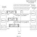
- the second multi-link device includes one or more scoreboards (scoreboards).
- the scoreboard is used for recording information about a receiving status of a data frame.
- the second multi-link device includes multiple scoreboards, each link is corresponding to one scoreboard, and the scoreboard is used for recording a receiving status of a data frame transmitted over a corresponding link.
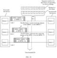
- the second multi-link device includes a scoreboard, and the scoreboard is used for recording receiving statuses of the data frames transmitted over all the links.
- a corresponding bit is set to 1; otherwise, a corresponding bit is set to 0.
- Values of the 4 th bit to the 9 th bit of the scoreboard 1 are 0.
- the 4 th bit to the 6 th bit of the scoreboard 2 are used for recording receiving statuses of the MPDU 7 to the MPDU 9 transmitted over the link 2, and values of other bits are 0.
- the 7 th bit to the 9 th bit of the scoreboard 3 are used for recording receiving statuses of the MPDU 10 to the MPDU 12 transmitted over the link 3, and values of other bits are 0.
- the station 1 of the second link device When the station 1 of the second link device generates the BA frame 1, the station 1 of the second link device obtains the receiving statuses of the MPDU 7 to the MPDU 9 from the scoreboard 2, and obtains the receiving statuses of the MPDU 10 to the MPDU 12 from the scoreboard 3.
- the station 1 generates the BA frame 1 based on the receiving statuses of the MPDU 4 to the MPDU 6 and the receiving statuses of the MPDU 7 to the MPDU 12 that are recorded by the scoreboard 1.
- the second link device has only one scoreboard. As shown in FIG. 18 , the second link device has a scoreboard, and the scoreboard has nine bits. A 1 st bit is corresponding to the MPDU 4, a 2 nd bit is corresponding to the MPDU 5, ..., and by analogy, a 9 th bit is corresponding to the MPDU 12.
- the first three bits of the scoreboard are used for recording receiving statuses of the MPDU 4 to the MPDU 6 transmitted over the link 1. If the MPDU is successfully received, a corresponding bit is set to 1; otherwise, a corresponding bit is set to 0.
- the 4 th bit to the 6 th bit of the scoreboard are used for recording receiving statuses of the MPDU 7 to the MPDU 9 transmitted over the link 2.
- the 7 th bit to the 9 th bit of the scoreboard are used for recording receiving statuses of the MPDU 10 to the MPDU 12 transmitted over the link 3.
- the station 1 of the second link device When the station 1 of the second link device generates the BA frame 1, the station 1 of the second link device obtains the recorded receiving statuses of the MPDU 4 to the MPDU 6 from the scoreboard, to generate the BA frame 1 based on the receiving statuses of the MPDU 4 to the MPDU 12.
- the second multi-link device may reply with the BA frame in either of the following two manners. Certainly, the second multi-link device may alternatively reply with the BA frame in another manner. This is not limited in this embodiment of this application.
- the second multi-link device may send the BA frame to the first multi-link device over the first link at a fixed time interval.
- the fixed time interval may be a short inter-frame space (short interframe space, SIFS).
- Manner 2 After the first multi-link device sends the data frames to the second multi-link device over the multiple links, the first multi-link device sends a BAR frame to the second multi-link device over the first link. After receiving the BAR frame over the first link, the second multi-link device sends the BA frame to the first multi-link device over the first link.
- the first multi-link device determines, based on a first time and a second time, a receiving status of a data frame corresponding to a first bit.
- the first multi-link device determines, based on the first time and the second time, the receiving status of the data frame corresponding to the first bit, where the first time is a transmission time of the data frame corresponding to the first bit, and the second time is a receiving time of the BA frame.
- the data frame corresponding to the first bit is sent over the second link, and a bit value corresponding to the first bit is a second value.
- a corresponding bit to a data frame in the bitmap may have the following four cases.
- Case 1 A data frame corresponding to the bit is sent over the first link. In this case, if a value of the bit is 1, it indicates that the data frame corresponding to the bit is successfully received. If the value of the bit is 0, it indicates that the data frame corresponding to the bit fails to be received. Alternatively, if a value of the bit is 0, it indicates that the data frame corresponding to the bit is successfully received. If the value of the bit is 1, it indicates that the data frame corresponding to the bit fails to be received.
- Case 2 A data frame corresponding to the bit has not been sent.
- a value of the bit indicates that the data frame corresponding to the bit has not been sent. Because the data frame is sent by the first multi-link device, the first multi-link device can determine which data frames have been sent. For example, if the data frame corresponding to the bit has not been sent, a value of the bit is 0.
- Case 3 A data frame corresponding to the bit is sent over the second link, and a bit value corresponding to the bit is the second value.
- the second value is a value set by the second multi-link device for a bit corresponding to the data frame when determining that the data frame is successfully received.
- the first multi-link device determines that the data frame corresponding to the bit is successfully received.
- a first value is different from the second value. For example, the second value is 1, and the first value is 0. Alternatively, the second value is 0, and the first value is 1.
- Case 4 A data frame corresponding to the bit is sent over the second link, and a bit value corresponding to the bit is a first value.
- the bit is the first bit.
- the second multi-link device may use the bit value corresponding to the bit as the first value because the data frame corresponding to the bit fails to be received, or may use the bit value corresponding to the bit as the first value because the station on the first link in the second multi-link device does not obtain a receiving status of the data frame corresponding to the bit.
- the first multi-link device determines, based on the first time and the second time, the receiving status of the data frame corresponding to the bit. In this embodiment of this application, how the first multi-link device determines the receiving status of the data frame corresponding to the first bit in the case 4 is mainly described.
- the transmission time of the data frame corresponding to the first bit is a sending end time of a downlink protocol data unit (PHY protocol data unit, PPDU) in which the data frame is located, or the transmission time of the data frame corresponding to the first bit is a sending end time of a symbol in which a last bit of the data frame is located.
- the sending end time of the downlink protocol data unit PPDU in which the data frame corresponding to the first bit is located or the sending end time of the symbol in which the last bit of the data frame corresponding to the first bit is located is used as the first time, to help improve accuracy of determining a receiving status of a data frame.
- a station on the second link in the second multi-link device Before the second multi-link device generates the BA frame, a station on the second link in the second multi-link device has sufficient time to transfer the receiving status of the data frame corresponding to the first bit to a station on the first link in the second multi-link device. Therefore, if the delay between the second time and the first time is greater than or equal to the first threshold, in addition to the sufficient time, if a receiving status of a data frame transmitted by a station on the second link to a station on the first link in the first multi-link device is not a success, it may be determined that the receiving status of the data frame corresponding to the first bit is the receiving failure. It can be learned that, based on this possible implementation, the receiving failure status of the data frame corresponding to the first bit can be accurately determined.
- the first multi-link device may first send an ADDBA request frame to the second multi-link device.
- the second multi-link device After receiving the ADDBA request frame, the second multi-link device sends an ADDBA response frame to the first multi-link device.
- the first information may be the ADDBA response frame, and the ADDBA response frame carries the first threshold.
- the second multi-link device may add a field to a frame body (frame body) field in the ADDBA response frame to carry the first threshold.
- the second multi-link device may include the first threshold in another field in the ADDBA response frame.
- the first multi-link device After the first multi-link device receives the BA frame, if the data frame corresponding to the first bit is a data frame sent over the link 1, the first multi-link device determines, based on the first time, the second time, and the first threshold corresponding to the link 1, the receiving status of the data frame corresponding to the first bit. If the data frame corresponding to the first bit is a data frame sent over the link 2, the first multi-link device determines, based on the first time, the second time, and the first threshold corresponding to the link 2, the receiving status of the data frame corresponding to the first bit.
- the station on the first link in the second multi-link device can determine, within the time period of the first threshold, the receiving status of the data frame received over the second link, it indicates that the second link supports the first threshold; otherwise, it indicates that the second link does not support the first threshold. Because the first threshold is a fixed value pre-specified in the protocol, the first threshold is not necessarily supported by the second link. When the second link supports the first threshold, the first multi-link device can accurately determine, based on the first threshold and the delay between the second time and the first time, receiving failure status of the data frame corresponding to the first bit.
- the BA frame carries a receiving status of a data frame
- the data frame is an MPDU.
- the first multi-link device determines that the receiving status of the data frame corresponding to the first bit is receiving failure. That is, the delay between the first time and the second time is duration between the end time of the PPDU in which the MPDU corresponding to the first bit is located and the transmission time of the BA frame.
- the first threshold is the MLIFS.
- the MLIFS may be an SIFS, a PIFS, or a DIFS.
- For a manner of obtaining the first threshold refer to the foregoing manner 2 of obtaining the first threshold.
- a PPDU transmitted over the link 2 carries the MPDU 7 to the MPDU 9.
- a time interval between an end time of the PPDU transmitted over the link 2 and a transmission time of the BA frame 1 exceeds the MLIFS. Therefore, the BA frame 1 carries the receiving statuses of the MPDU 7 to the MPDU 9. If an MPDU is successfully received, a bit value corresponding to the MPDU in the BA frame 1 is 1. If an MPDU fails to be received, a bit value corresponding to the MPDU in the BA frame 1 is 0.
- the first multi-link device After receiving the BA frame 1, the first multi-link device determines that an interval between the transmission time of the BA frame 1 and the end time of the PPDU in which the MPDU 8 with a bit value of 0 is located is greater than the MLIFS. Therefore, the first multi-link device determines that the BA frame 1 carries the receiving status of the MPDU 8. Because the bit value corresponding to the MPDU 8 is 0, the first multi-link device determines that the receiving status of the MPDU 8 is receiving failure.
- a time interval between an end time of a PPDU transmitted over the link 3 and the transmission time of the BA frame 1 does not exceed the MLIFS. Therefore, the BA frame 1 does not carry the receiving statuses of the MPDU 10 to the MPDU 12.
- the first multi-link device determines that an interval between a receiving time of the BA frame 1 and the end time of the PPDU in which the MPDU 10 to the MPDU 12 with bit values of 0 are located is less than the MLIFS. Therefore, the first multi-link device determines that the BA frame 1 does not carry the receiving statuses of the MPDU 10 to the MPDU 12.
- Manner 2 If an MPDU is carried in one or more OFDM symbols of a PPDU, and a time interval between an end time of a last OFDM symbol that carries the MPDU and the transmission time of the BA frame exceeds an MLIFS, an acknowledgment status (or a receiving status) of the MPDU is carried in the BA frame (if an MPDU is carried in one or more OFDM symbols of a PPDU, and the duration from the ending of the last OFDM symbol that carries the MPDU to the transmission time of the BA has exceeded MLIFS, then the ACK status of that MPDU is carried in the BA frame).
- the end time of the last OFDM symbol that carries the MPDU may also be understood as an end time of an OFDM symbol in which a last bit of the data frame is located.
- the end time of the OFDM symbol may be a sending end time of the OFDM symbol or a receiving end time of the OFDM symbol.
- the first multi-link device determines that the receiving status of the data frame corresponding to the first bit is receiving failure. That is, the delay between the first time and the second time is duration between the end time of the last OFDM symbol that carries the MPDU corresponding to the first bit and the transmission time of the BA frame.
- the first threshold is the MLIFS.
- the MLIFS may be an SIFS, a PIFS, or a DIFS.
- For a manner of obtaining the first threshold refer to the foregoing manner 2 of obtaining the first threshold.
- a PPDU transmitted over the link 2 includes a symbol (Symbol) 1 to a symbol (Symbol) 3.
- the symbol 1 carries the MPDU 7 and the MPDU 8
- the symbol 2 carries the MPDU 9 and the MPDU 10
- the symbol 3 carries the MPDU 11 and the MPDU 12.
- a time interval between an end time of the symbol 1 transmitted over the link 2 and a transmission time of the BA frame 1 exceeds the MLIFS. Therefore, the BA frame 1 carries the receiving statuses of the MPDU 7 and the MPDU 8.
- a time interval between an end time of the symbol 2 transmitted over the link 2 and the transmission time of the BA frame 1 exceeds the MLIFS. Therefore, the BA frame 1 carries the receiving statuses of the MPDU 9 and the MPDU 10.
- a time interval between an end time of the symbol 3 transmitted over the link 2 and the transmission time of the BA frame 1 does not exceed the MLIFS. Therefore, the BA frame 1 does not carry the receiving statuses of the MPDU 11 and the MPDU 12.
- a bit value corresponding to the MPDU in the BA frame 1 is 1. If an MPDU fails to be received, a bit value corresponding to the MPDU in the BA frame 1 is 0.
- the first multi-link device determines that an interval between the end time of the symbol 1 in which the MPDU 8 with a bit value of 0 is located and a receiving time of the BA frame 1 is greater than the MLIFS. Therefore, the first multi-link device determines that the BA frame 1 carries the receiving status of the MPDU 8. The bit value corresponding to the MPDU 8 is 0. Therefore, the first multi-link device determines that the receiving status of the MPDU 8 is receiving failure.
- the first multi-link device determines that an interval between the end time of the symbol 2 in which the MPDU 10 with a bit value of 0 is located and the receiving time of the BA frame 1 is greater than the MLIFS. Therefore, the first multi-link device determines that the receiving status of the MPDU 10 carried in the BA frame 1 is receiving failure. The first multi-link device determines that an interval between the end time of the symbol 3 in which the MPDU 11 and the MPDU 12 with bit values of 0 are located and the receiving time of the BA frame 1 is less than the MLIFS. Therefore, the first multi-link device determines that the BA frame 1 does not carry the receiving statuses of the MPDU 11 and the MPDU 12.
- Manner 3 If an MPDU is carried in a PPDU, and a time interval between an end time of the PPDU and a transmission time of the BA frame exceeds a time threshold M, an acknowledgment status (or a receiving status) of the MPDU is carried in the BA frame (if an MPDU is carried in a PPDU, and the duration from the ending of the PPDU to the transmission time of the BA has exceeded a time threshold M, then the ACK status of that MPDU is carried in the BA frame).
- the end time of the PPDU may be a sending end time of the PPDU or a receiving end time of the OFDM symbol.
- the first multi-link device determines that the receiving status of the data frame corresponding to the first bit is receiving failure. That is, the delay between the first time and the second time is duration between the end time of the PPDU in which the MPDU corresponding to the first bit is located and the transmission time of the BA frame.
- the first threshold is the time threshold M.
- a manner of obtaining the first threshold refer to the foregoing manner 1 of obtaining the first threshold.
- a specific implementation principle of FIG. 21 is the same as that of FIG. 19 , and the MLIFS in FIG. 19 is replaced with the time threshold M. Details are not described herein again.
- Manner 4 If an MPDU is carried in one or more OFDM symbols of a PPDU, and a time interval between an end time of a last OFDM symbol that carries the MPDU and a transmission time of the BA frame exceeds a time threshold M, an acknowledgment status (or a receiving status) of the MPDU is carried in the BA frame (if an MPDU is carried in one or more OFDM symbols of a PPDU, and the duration from the ending of the last OFDM symbol that carries the MPDU to the transmission time of the BA has exceeded a time threshold M, then the ACK status of that MPDU is carried in the BA frame).
- the acknowledgment status of the MPDU is a receiving status of the MPDU.
- the end time of the last OFDM symbol that carries the MPDU may also be understood as an end time of an OFDM symbol in which a last bit of the data frame is located.
- the end time of the OFDM symbol may be a sending end time of the OFDM symbol or a receiving end time of the OFDM symbol.
- the first multi-link device determines that the receiving status of the data frame corresponding to the first bit is receiving failure. That is, the delay between the first time and the second time is duration between the end time of the last OFDM symbol that carries the MPDU corresponding to the first bit and the transmission time of the BA frame.
- the first threshold is the time threshold M.
- a manner of obtaining the first threshold refer to the foregoing manner 1 of obtaining the first threshold.
- a specific implementation principle of FIG. 22 is the same as that of FIG. 20 , and the MLIFS in FIG. 20 is replaced with the time threshold M. Details are not described herein again.
- the transmission time of the BA frame in the four manners in which the BA frame carries the receiving status of the data frame may be replaced with the receiving time of the BA frame.
- a specific implementation principle after replacement is the same, and details are not described herein again.
- the second multi-link device may send, to the first multi-link device, information about a capability of the second multi-link device to transmit a multi-link BA frame.
- the capability information may include one or more capability levels.
- the multi-link BA frame indicates that the BA frame includes receiving statuses of data frames transmitted over multiple links.
- the capability information may be carried in an ADDBA (add block acknowledgment) response frame or an EHT capabilities information element of an association request (association request)/re-association request (re-association request)/authentication (authentication)/probe request (probe request) frame, to be sent to the first multi-link device.
- the first multi-link device can learn of the capability of the second multi-link device to transmit the multi-link BA frame. In this way, the first multi-link device parses, in a correct parsing manner, a receiving status of a data frame indicated by the bitmap in the BA frame.
- the capability information may include one or more of the following three capability levels.
- Capability level 1 The second multi-link device does not support transmission of a multi-link BA frame.
- a BA frame carries only a receiving status of an MPDU sent over a same link, and does not carry a receiving status of an MPDU sent over another link.
- Capability level 2 The second multi-link device supports transmission of a PPDU-based multi-link BA frame.
- the BA frame carries a receiving status of an MPDU sent over a same link.
- the BA frame further carries a receiving status of an MPDU sent over another link that meets the following condition: A time interval between an end time of a PPDU in which the MPDU is located and a transmission time of the BA frame is greater than a first threshold.
- the BA frame carries a receiving status of an MPDU sent over the first link.
- the BA frame further carries a receiving status of an MPDU sent over the second link that meets the following condition: A time interval between an end time of a PPDU in which the MPDU is located and a transmission time of the BA frame is greater than the first threshold.
- the first threshold is an MLFS.
- the BA frame 1 sent by the second multi-link device carries the receiving statuses of the MPDU 4 to the MPDU 6 sent over the link 1.
- the BA frame 1 further carries the receiving statuses of the MPDU 7 to the MPDU 9 sent over the link 2.
- the first threshold is a time threshold M.
- the BA frame 1 sent by the second multi-link device carries the receiving statuses of the MPDU 4 to the MPDU 6 sent over the link 1.
- the BA frame 1 further carries the receiving statuses of the MPDU 7 to the MPDU 9 sent over the link 2.
- Capability level 3 The second multi-link device supports transmission of an MPDU-based multi-link BA frame.
- the BA frame carries a receiving status of an MPDU sent over a same link.
- the BA frame further carries a receiving status of an MPDU sent over another link that meets the following condition: A time interval between an end time of a last OFDM symbol in one or more OFDM symbols in which the MPDU is located and a transmission time of the BA frame is greater than the first threshold.
- the BA frame carries a receiving status of an MPDU sent over the first link.
- the BA frame further carries a receiving status of an MPDU sent over the second link that meets the following condition: A time interval between an end time of a last OFDM symbol in one or more OFDM symbols in which the MPDU is located and a transmission time of the BA frame is greater than the first threshold.
- the first threshold is an MLFS.
- the BAframe 1 sent by the second multi-link device carries the receiving statuses of the MPDU 4 to the MPDU 6 sent over the link 1.
- a time interval between an end time of a last OFDM symbol in one or more OFDM symbols in which the MPDU 7 to the MPDU 10 sent over the link 2 are located and the transmission time of the BA frame is greater than the MLFS, the BA frame 1 further carries the receiving statuses of the MPDU 7 to the MPDU 10 sent over the link 2.
- the first threshold is a time threshold M.
- the BA frame 1 sent by the second multi-link device carries the receiving statuses of the MPDU 4 to the MPDU 6 sent over the link 1.
- a time interval between an end time of a last OFDM symbol in one or more OFDM symbols in which the MPDU 7 to the MPDU 10 sent over the link 2 are located and the transmission time of the BA frame is greater than the time threshold M, the BA frame 1 further carries the receiving statuses of the MPDU 7 to the MPDU 10 sent over the link 2.
- the transmission time of the BA frame at the capability level 2 and the capability level 3 may alternatively be replaced with a receiving time of the BA frame.
- the first multi-link device determines that the station corresponding to the first link in the second multi-link device does not obtain the receiving status of the data frame corresponding to the first bit, where the second threshold is less than the first threshold. If the delay between the second time and the first time is less than the second threshold, it indicates that before the second multi-link device generates the BA frame, the station on the second link in the second multi-link device does not have sufficient time to transfer the receiving status of the data frame corresponding to the first bit to the station on the first link in the second multi-link device.
- step 801 and step 802 refer to the specific implementations of step 401 and step 402. Details are not described herein.
- the first multi-link device determines a first data frame sent over the second link.
- the first multi-link device After receiving the BA frame, the first multi-link device determines the first data frame sent over the second link.
- the first data frame is a data frame whose transmission time is the last in a data frame set, and the data frame set includes a data frame that is sent over the second link and that has been correctly received.
- a bit value corresponding to the data frame that is sent over the second link and that has been correctly received is a second value.
- the first multi-link device determines that a receiving status of a second data frame is receiving failure.
- the first multi-link device determines that the receiving status of the second data frame is receiving failure.
- the second data frame is a data frame sent over the second link before the first data frame, and a bit value corresponding to the second data frame in the bitmap is a first value.
- the first value is different from the second value.
- the second value indicates that the data frame is successfully received. For example, the first value is 0, and the second value is 1. Alternatively, the first value is 1, and the second value is 0.
- the indication information may be 1-bit information, and is carried in a 6 th bit (B5) in a block acknowledgment parameter set (block ack parameter set) field in an ADDBA (add block acknowledgment) response frame, for example, as shown in FIG. 23 .
- the first multi-link device determines, from the MPDU 7 to the MPDU 9, that MPDUs that have been successfully received are the MPDU 7 and the MPDU 9.
- the MPDU 9 is a successfully received MPDU that is sent last in the MPDU 7 and the MPDU 9. Therefore, the MPDU 9 is the first data frame. Because the MPDU 8 is sent before a first data frame, and a bit value corresponding to the MPDU 8 is 0, the MPDU 8 is the second data frame.
- the first multi-link device determines that a receiving status of the MPDU 8 is receiving failure.
- the BA frame is a BA frame 1
- a bit value in a bitmap of the BA frame 1 is 1, an MPDU is successfully received.
- a 4 th bit to a 6 th bit are corresponding to an MPDU 7 to an MPDU 9 transmitted over the link 2.
- a 7 th bit to a 9 th bit are corresponding to an MPDU 10 to an MPDU 12 transmitted over the link 3.
- the MPDU 11 is the first data frame.
- the MPDU 8 and the MPDU 10 are second data frames.
- the MPDU 12 is the third data frame. Therefore, the first multi-link device determines that the receiving statuses of the MPDU 8 and the MPDU 10 are receiving failure.
- FIG. 9 is a schematic flowchart of a block acknowledgment frame transmission method according to an embodiment of this application.
- the block acknowledgment frame transmission method includes the following step 901 to step 903.
- the method shown in FIG. 9 may be performed by a first multi-link device and a second multi-link device.
- the method shown in FIG. 9 may be executed by a chip in the first multi-link device and a chip in the second multi-link device.
- FIG. 9 is described by using an example in which the first multi-link device and the second multi-link device are used as execution bodies.
- the first multi-link device sends data frames to the second multi-link device over multiple links.
- step 901 For a specific implementation of step 901, refer to the specific implementation of step 401. Details are not described herein.
- the first multi-link device sends a block acknowledgment request BAR frame to the second multi-link device.
- the first multi-link device after sending the data frames to the second multi-link device over the multiple links, sends the block acknowledgment request BAR frame to the second multi-link device.
- the BAR frame carries first indication information, and the first indication information indicates a type of a requested block acknowledgment BA frame.
- the type of the BA frame may be a single-link BA frame type or a multi-link BA frame type.
- the single-link BA frame type indicates that a BA frame includes only a receiving status of a data frame transmitted over one link.
- the multi-link BA frame type indicates that a BA frame includes only receiving statuses of data frames transmitted over multiple links.
- a value of the first indication information may be a reserved value of a BAR type field in an existing standard.
- the value of the first indication information may be any one of 4, 5, or 11 to 15.
- a value of the BAR type field when a value of the BAR type field is 4, it indicates that the type of the requested BA frame is the multi-link BA frame.
- the value of the BAR type When the value of the BAR type is 0, it indicates that the BAR type is a basic type.
- the value of the BAR type When the value of the BAR type is 1, it indicates that the BAR type is an extended compressed type.
- the value of the BAR type is 2, the BAR type is a compressed type.
- the value of the BAR type When the value of the BAR type is 3, it indicates that the BAR type is a multi-service type.
- a value of 5 of the BAR type is a reserved value.
- the value of the BAR type 6 it indicates that the BAR type is a groupcast with retries type. Values of 7 to 9 of the BAR type are reserved values.
- BAR Type field BAR frame variant (BlockAckReq frame variant) 0 Basic (Basic) 1 Extended compressed (Extended Compressed) 2 Compressed (Compressed) 3 Multi-service type (Multi-TID) 4 Multi-link (Multi-link) 5 Reserved (Reserved) 6 Groupcast with retries (groupcast with retries, GCR) 7 to 9 Reserved (Reserved) 10 General link groupcast with retries (general link groupcast with retries, GLK-GCR) 11 to 15 Reserved (Reserved)
- a value of the BAR type field is any one of 11 to 14, it indicates that the type of the requested BA frame is a multi-link BA frame.
- the value of the BAR type is 11, it indicates that the BAR type is a basic type, and a BAR is used for requesting a multi-link BA frame.
- the value of the BAR type is 12, it indicates that the BAR type is an extended compressed type, and the BAR is used for requesting a multi-link BA frame.
- the value of the BAR type is 13 it indicates that the BAR type is a compressed type, and the RAR is used for requesting a multi-link BA frame.
- BAR type field BAR frame variant (BlockAckReq frame variant) 0 Basic (Basic) 1 Extended compressed (Extended Compressed) 2 Compressed (Compressed) 3 Multi-service type (Multi-TID) 4 and 5 Reserved (Reserved) 6 Groupcast with retries (groupcast with retries, GCR) 7 to 9 Reserved (Reserved) 10 General link groupcast with retries (general link groupcast with retries, GLK-GCR) 11 Multi-link basic (Multi-link Basic) 12 Multi-link extended compressed (Multi-link Extended Compressed) 13 Multi-link compressed (Multi-link Compressed) 14 Multi-link multi-service type (Multi-link Multi-TID) 15 Reserved (Reserved)
- the BAR frame further includes second indication information
- the second indication information indicates one or more links in the multiple links
- the first BA frame indicates a receiving status of a data frame sent over the one or more links.
- the second indication information is located in a BAR control field in the BAR frame.
- the second indication information may be specifically a link bitmap.
- the first multi-link device can indicate, to the second multi-link device, that the second multi-link device needs to feed back receiving statuses of data frames sent over which links.
- the second multi-link device includes multiple scoreboards, each link is corresponding to one scoreboard, and the scoreboard is used for recording a receiving status of a data frame transmitted over a corresponding link. In this way, the second multi-link device can distinguish between receiving statuses of data frames transmitted over different links, to feed back different types of BA frames.
- the first multi-link device may further receive a reply manner of a BA frame sent by the second multi-link device, where the reply manner of the BA frame is delayed reply or immediate reply.
- the reply manner of the BA frame may be carried in a frame body field in an ADDBA response frame.
- the reply manner of the BA frame may be carried in a block acknowledgment parameter set (Block Ack Parameter Set) of the frame body field in the ADDBA response frame.
- Block Ack Parameter Set Block Ack Parameter Set
- the first multi-link device can determine the reply manner of the BA frame sent by the second multi-link device.
- the second multi-link device sends a first BA frame to the first multi-link device, where the first BA frame is a BA frame of the type indicated by the first indication information.
- a time interval between a transmission end time of the BAR frame and a transmission start time of the first BA frame is greater than or equal to a preset threshold. Based on this possible implementation, the second multi-link device has sufficient time to generate the BA frame.
- the padding bit enables the time interval between the transmission end time of the BAR frame and the transmission start time of the first BA frame to be greater than or equal to the preset threshold. Based on this possible implementation, the time interval between the transmission end time of the BAR frame and the transmission start time of the first BA frame can be greater than the preset threshold.
- the first multi-link device can flexibly obtain different types of BA frames based on different requirements.
- the block acknowledgment frame transmission method described in FIG. 9 may be implemented independently.
- the block acknowledgment frame transmission method described in FIG. 9 may be combined with the embodiment corresponding to the foregoing method for determining a receiving status of a data frame. For example, in the method for determining a receiving status of a data frame in FIG. 4 or FIG.
- the first multi-link device sends a block acknowledgment request BAR frame to the second multi-link device.
- the BAR frame carries first indication information, and the first indication information indicates that a type of a requested block acknowledgment BA frame is a multi-link BAframe.
- the first indication information is located in the BAR type field in the BAR frame.
- a value of the first indication information may be a reserved value of a BAR type field in an existing standard.
- a new field may be added to the BAR frame, and the first indication information may alternatively be located in the new field in the BAR frame.
- the BAR frame further includes second indication information, the second indication information indicates one or more second links in the multiple links, and the BA frame indicates a receiving status of a data frame sent over the one or more second links.
- the first multi-link device may further receive a reply manner of the BA frame sent by the second multi-link device, where the reply manner of the BA frame is delayed reply or immediate reply.
- a time interval between a transmission end time of the BAR frame and a transmission start time of the BA frame is greater than a preset threshold.
- there is a padding bit behind the BAR frame and the padding bit enables the time interval between the transmission end time of the BAR frame and the transmission start time of the BA frame to be greater than the preset threshold.
- FIG. 14 is a schematic flowchart of a data frame transmission method according to an embodiment of this application.
- the data frame transmission method includes the following step 1401 to step 1403.
- the method shown in FIG. 14 may be performed by a first multi-link device and a second multi-link device.
- the method shown in FIG. 14 may be executed by a chip in the first multi-link device and a chip in the second multi-link device.
- FIG. 14 is described by using an example in which the first multi-link device and the second multi-link device are used as execution bodies.
- the first multi-link device sends data frames to the second multi-link device over a first link and a second link, where a transmission end time of a PPDU in which the data frame transmitted over the first link is located is the same as a transmission end time of a PPDU in which the data frame transmitted over the second link is located.
- an end time of the PPDU in which the data frame transmitted over the first link is located is t1.
- An end time of the PPDU in which the data frame transmitted over the second link is located is t2.
- t1 is the same as t2.
- the first multi-link device sends a block acknowledgment request BAR frame to the second multi-link device over the first link and/or the second link.
- the first multi-link device after sending data frames to the second multi-link device over the first link and the second link, the first multi-link device sends a block acknowledgment request BAR frame to the second multi-link device over the first link and/or the second link.
- the second multi-link device sends a BA frame to the first multi-link device over the first link and/or the second link.
- the second multi-link device after receiving, over the first link and/or the second link, the BAR frame sent by the first multi-link device, the second multi-link device sends the BA frame to the first multi-link device over the first link and/or the second link.
- the BA frame includes receiving statuses of data frames transmitted over multiple links.
- the first multi-link device may receive the BA frame over the first link and/or the second link.
- the padding bit enables the transmission end time of the PPDU in which the data frame transmitted over the first link is located to be the same as the transmission end time of the PPDU in which the data frame transmitted over the second link is located, for example, as shown in FIG. 16 .
- the transmission end time of the PPDU in which the data frame transmitted over the first link is located is the same as the transmission end time of the PPDU in which the data frame transmitted over the second link is located. This helps avoid interruption of a transmit opportunity (transmit opportunity, TXOP).
- TXOP transmit opportunity
- the data frame transmission method described in FIG. 14 may be implemented independently. Alternatively, the data frame transmission method described in FIG. 14 may be combined with the embodiment corresponding to the foregoing method for determining a receiving status of a data frame. For example, in the method for determining a receiving status of a data frame in FIG. 4 or FIG.
- the first multi-link device sends the data frames to the second multi-link device over the multiple links, where an end time of a PPDU in which a data frame sent over each link is located is the same.
- the first multi-link device sends the data frames to the second multi-link device over the multiple links, and before the first multi-link device receives, over the first link in the multiple links, the block acknowledgment BA frame sent by the second multi-link device, the first multi-link device sends a BAR frame to the second multi-link device.
- there is a padding bit behind a data frame sent over at least one link and the padding bit enables the end time of the PPDU in which the data frame sent over each link is located is the same.
- the data frame transmission method described in FIG. 14 may be combined with the block acknowledgment frame transmission method described in FIG. 9 .
- the first multi-link device sends the data frames to the second multi-link device on the multiple links, where an end time of a PPDU in which a data frame sent over each link is located is the same.
- the BAR frame sent by the first multi-link device to the second multi-link device indicates that the type of the BA frame is the multi-link BA frame.
- there is a padding bit behind a data frame sent over at least one link and the padding bit enables the end time of the PPDU in which the data frame sent over each link is located is the same.
- FIG. 24 is a schematic diagram of a structure of a communication apparatus according to an embodiment of this application.
- the communication apparatus shown in FIG. 24 may be configured to perform some or all functions of the first multi-link device in the method embodiment described in FIG. 4 .
- the apparatus may be a first multi-link device, or an apparatus in the first multi-link device, or an apparatus that can be used together with the first multi-link device.
- the communication apparatus may alternatively be a chip system.
- the communication apparatus shown in FIG. 24 may include a communication unit 2401 and a processing unit 2402.
- the communication unit may alternatively be referred to as a transceiver unit, or the communication unit includes a receiving unit and a sending unit.
- the processing unit 2402 is configured to perform data processing.
- the communication unit 2401 is configured to send data frames to a second multi-link device over multiple links.
- the communication unit 2401 is further configured to receive a block acknowledgment BA frame sent by the second multi-link device over a first link in the multiple links, where the BA frame carries a bitmap, the bitmap indicates a receiving status of a data frame transmitted over the first link and indicates a receiving status of a data frame transmitted over a second link in the multiple links.
- the processing unit 2402 is configured to determine, based on a first time and a second time, a receiving status of a data frame corresponding to a first bit, where the first time is a transmission time of the data frame corresponding to the first bit, and the second time is a receiving time of the BA frame.
- the first bit is a bit that is in the bitmap and that is corresponding to the data frame transmitted over the second link, and a value of the first bit is a first value.
- a manner in which the processing unit 2402 determines, based on the first time and the second time, the receiving status of the data frame corresponding to the first bit is specifically: if a delay between the second time and the first time is greater than or equal to a first threshold, determine that the receiving status of the data frame corresponding to the first bit is receiving failure.
- T is the delay between the second time and the first time
- t2 is the second time
- t1 is the first time
- t3 is a propagation delay between the first multi-link device and the second multi-link device.
- the communication unit 2401 is further configured to: before sending the data frames to the second multi-link device over the multiple links, receive first information sent by the second multi-link device, where the first information carries the first threshold.
- the first information includes multiple first thresholds, and each of the multiple first thresholds is corresponding to one link.
- the communication unit 2401 is further configured to: before sending the data frames to the second multi-link device over the multiple links, receive indication information sent by the second multi-link device, where the indication information indicates whether the second multi-link device can determine, within a time period of the first threshold, the receiving status of the data frame received over the second link.
- the transmission time of the data frame corresponding to the first bit is a sending end time of a downlink protocol data unit PPDU in which the data frame is located, or the transmission time of the data frame corresponding to the first bit is a sending end time of a symbol in which a last bit of the data frame is located.
- the communication unit 2401 is further configured to: if the delay between the second time and the first time is greater than a second threshold, and the delay between the second time and the first time is less than the first threshold, send a block acknowledgment request BAR frame or a data frame to the second multi-link device before retransmitting the data frame corresponding to the first bit.
- the BA frame includes a start sequence number of a data frame whose receiving status is fed back, the start sequence number is less than or equal to a first sequence number, and the first sequence number is a smallest value of sequence numbers of data frames that are not acknowledged to be received.
- FIG. 24 is a schematic diagram of a structure of a communication apparatus according to an embodiment of this application.
- the communication apparatus shown in FIG. 24 may be configured to perform some or all functions of the first multi-link device in the method embodiment described in FIG. 8 .
- the apparatus may be a first multi-link device, or an apparatus in the first multi-link device, or an apparatus that can be used matching the first multi-link device.
- the communication apparatus may alternatively be a chip system.
- the communication apparatus shown in FIG. 24 may include a communication unit 2401 and a processing unit 2402.
- the communication unit may alternatively be referred to as a transceiver unit, or the communication unit includes a receiving unit and a sending unit.
- the processing unit 2402 is configured to perform data processing.
- the communication unit 2401 is configured to send data frames to a second multi-link device over multiple links.
- the communication unit 2401 is further configured to receive a block acknowledgment BA frame sent by the second multi-link device over a first link in the multiple links, where the BA frame carries a bitmap, the bitmap indicates a receiving status of a data frame transmitted over the first link and a receiving status of a data frame transmitted over a second link in the multiple links.
- the processing unit 2402 is configured to determine a first data frame sent over the second link, where the first data frame is a data frame whose transmission time is the last in a data frame set, and the data frame set includes a data frame that is sent over the second link and that has been correctly received.
- the processing unit 2402 is further configured to determine that a receiving status of a second data frame is receiving failure, where the second data frame is a data frame sent over the second link before the first data frame, and a bit value corresponding to the second data frame in the bitmap is a first value.
- the communication unit 2401 is further configured to: before retransmitting a third data frame, send a block acknowledgment request BAR frame or a data frame to the second multi-link device, where a bit value corresponding to the third data frame in the bitmap is the first value, and the third data frame is a data frame sent over the second link after the first data frame.
- the BA frame includes a start sequence number of a data frame whose receiving status is fed back, the start sequence number is less than or equal to a first sequence number, and the first sequence number is a smallest value of sequence numbers of data frames that are not acknowledged to be received.
- the data frame set includes data frames that are sent over multiple second links and that have been correctly received by the second link device.
- FIG. 24 is a schematic diagram of a structure of a communication apparatus according to an embodiment of this application.
- the communication apparatus shown in FIG. 24 may be configured to perform some or all functions of the first multi-link device in the method embodiment described in FIG. 9 .
- the apparatus may be a first multi-link device, or an apparatus in the first multi-link device, or an apparatus that can be used matching the first multi-link device.
- the communication apparatus may alternatively be a chip system.
- the communication apparatus shown in FIG. 24 may include a communication unit 2401 and a processing unit 2402.
- the communication unit may alternatively be referred to as a transceiver unit, or the communication unit includes a receiving unit and a sending unit.
- the processing unit 2402 is configured to perform data processing.
- the communication unit 2401 is configured to send data frames to a second multi-link device over multiple links.
- the communication unit 2401 is further configured to send a block acknowledgment request BAR frame to the second multi-link device, where the BAR frame carries first indication information, and the first indication information indicates a type of a requested block acknowledgment BA frame.
- the communication unit 240 is further configured to receive a first BA frame sent by the second multi-link device, where the first BA frame is a BA frame of the type indicated by the first indication information.
- the first indication information is located in a BAR type field in the BAR frame.
- the BAR frame further includes second indication information, the second indication information indicates one or more links in the multiple links, and the first BA frame indicates a receiving status of a data frame sent over the one or more links.
- the first indication information indicates that the type of the requested BA frame is a multi-link BA frame, and an interval between a transmission end time of the data frames and a transmission start time of the BAR frame is greater than or equal to a preset time interval.
- the communication unit 2401 before the first multi-link device sends the data frames to the second multi-link device over the multiple links, the communication unit 2401 is further configured to receive a reply manner of a BAframe sent by the second multi-link device, where the reply manner of the BAframe is delayed reply or immediate reply.
- a time interval between a transmission end time of the BAR frame and a transmission start time of the first BA frame is greater than a preset threshold.
- the padding bit enables the time interval between the transmission end time of the BAR frame and the transmission start time of the first BA frame to be greater than the preset threshold.
- FIG. 24 is a schematic diagram of a structure of a communication apparatus according to an embodiment of this application.
- the communication apparatus shown in FIG. 24 may be configured to perform some or all functions of the second multi-link device in the method embodiment described in FIG. 9 .
- the apparatus may be a second multi-link device, or an apparatus in the second multi-link device, or an apparatus that can be used with the second multi-link device.
- the communication apparatus may alternatively be a chip system.
- the communication apparatus shown in FIG. 24 may include a communication unit 2401 and a processing unit 2402.
- the communication unit may alternatively be referred to as a transceiver unit, or the communication unit includes a receiving unit and a sending unit.
- the processing unit 2402 is configured to perform data processing.
- the communication unit 2401 is configured to receive, over multiple links, data frames sent by a first multi-link device.
- the communication unit 2401 is further configured to receive a block acknowledgment request BAR frame sent by the first multi-link device, where the BAR frame carries first indication information, and the first indication information indicates a type of a requested block acknowledgment BA frame.
- the communication unit 2401 is further configured to send a first BA frame to the first multi-link device, where the first BA frame is a BA frame of the type indicated by the first indication information.
- the first indication information is located in a BAR type field in the BAR frame.
- the BAR frame further includes second indication information, the second indication information indicates one or more links in the multiple links, and the first BA frame indicates a receiving status of a data frame sent over the one or more links.
- the first indication information indicates that the type of the requested block acknowledgment BA frame is a multi-link BA frame, and an interval between a transmission end time of the data frames and a transmission start time of the BAR frame is greater than or equal to a preset time interval.
- the padding bit enables the time interval between the transmission end time of the BAR frame and the transmission start time of the first BA frame to be greater than the preset threshold.
- FIG. 24 is a schematic diagram of a structure of a communication apparatus according to an embodiment of this application.
- the communication apparatus shown in FIG. 24 may be configured to perform some or all functions of the first multi-link device in the method embodiment described in FIG. 14 .
- the apparatus may be a first multi-link device, or an apparatus in the first multi-link device, or an apparatus that can be used matching the first multi-link device.
- the communication apparatus may alternatively be a chip system.
- the communication apparatus shown in FIG. 24 may include a communication unit 2401 and a processing unit 2402.
- the communication unit may alternatively be referred to as a transceiver unit, or the communication unit includes a receiving unit and a sending unit.
- the processing unit 2402 is configured to perform data processing.
- the communication unit 2401 is configured to send data frames to a second multi-link device over a first link and a second link, where a transmission end time of a PPDU in which the data frame transmitted over the first link is located is the same as a transmission end time of a PPDU in which the data frame transmitted over the second link is located.
- the communication unit 2401 is further configured to send a block acknowledgment request BAR frame to the second multi-link device over the first link and/or the second link.
- the communication unit 2401 is further configured to receive a BA frame over the first link and/or the second link.
- there is a padding bit behind the data frame transmitted over the first link and the padding bit enables the transmission end time of the PPDU in which the data frame transmitted over the first link is located to be the same as the transmission end time of the PPDU in which the data frame transmitted over the second link is located.
- FIG. 24 is a schematic diagram of a structure of a communication apparatus according to an embodiment of this application.
- the communication apparatus shown in FIG. 24 may be configured to perform some or all functions of the second multi-link device in the method embodiment described in FIG. 14 .
- the apparatus may be a second multi-link device, or an apparatus in the second multi-link device, or an apparatus that can be used with the second multi-link device.
- the communication apparatus may alternatively be a chip system.
- the communication apparatus shown in FIG. 24 may include a communication unit 2401 and a processing unit 2402.
- the communication unit may alternatively be referred to as a transceiver unit, or the communication unit includes a receiving unit and a sending unit.
- the processing unit 2402 is configured to perform data processing.
- the communication unit 2401 is configured to receive, over a first link and a second link, data frames sent by a first multi-link device, where a transmission end time of a PPDU in which the data frame transmitted over the first link is located is the same as a transmission end time of a PPDU in which the data frame transmitted over the second link is located.
- the communication unit 2401 is configured to receive, over the first link and/or the second link, a block acknowledgment request BAR frame sent by the first multi-link device.
- the communication unit 2401 is configured to send a BA frame to the first multi-link device over the first link and/or the second link.
- there is a padding bit behind the data frame transmitted over the first link and the padding bit enables the transmission end time of the PPDU in which the data frame transmitted over the first link is located to be the same as the transmission end time of the PPDU in which the data frame transmitted over the second link is located.
- FIG. 25a shows a communication apparatus 250 according to an embodiment of this application.
- the communication apparatus 250 is configured to implement functions of the first multi-link device in the method embodiments described in FIG. 4 , FIG. 8 , FIG. 9 , or FIG. 14 ; or is configured to implement functions of the second multi-link device in the method embodiments described in FIG. 4 , FIG. 8 , FIG. 9 , or FIG. 14 .
- the apparatus may be the first multi-link device or the second multi-link device, or the apparatus may be an apparatus used in the first multi-link device or an apparatus used in the second multi-link device.
- the apparatus used in the first multi-link device or the second multi-link device may be a chip system or a chip in the first multi-link device or the second multi-link device.
- the chip system may include a chip, or may include a chip and another discrete component.
- the communication apparatus 250 includes at least one processor 2525, configured to implement a data processing function of the first multi-link device or the second multi-link device of this application.
- the apparatus 250 may further include a communication interface 2510, configured to implement sending and receiving operations of the first multi-link device or the second multi-link device in this application.
- the communication interface may be a transceiver, a circuit, a bus, a module, or a communication interface of another type, and is configured to communicate with another device through a transmission medium.
- the communication interface 2510 is used by an apparatus in the apparatus 250 to communicate with another device.
- the processor 2525 receives and sends data through the communication interface 2510, and is configured to implement the methods in the foregoing method embodiments.
- the apparatus 250 may further include at least one memory 2530, configured to store program instructions and/or data.
- the memory 2530 is coupled to the processor 2525. Coupling in this embodiment of this application is indirect coupling or a communication connection between apparatuses, units, or modules, and may be in an electrical, mechanical, or another form, and is used for information exchange between the apparatuses, units, or modules.
- the processor 2525 may operate with the memory 2530 collaboratively.
- the processor 2525 may execute the program instructions stored in the memory 2530. At least one of the at least one memory may be included in the processor.
- a specific connection medium between the communication interface 2510, the processor 2525, and the memory 2530 is not limited in this embodiment of this application.
- the memory 2530, the processor 2525, and the communication interface 2510 are connected through a bus 2540 in FIG. 25a .
- the bus is represented by using a bold line in FIG. 25a .
- a connection manner between other components is merely an example for description, and is not limited thereto.
- the bus may be classified into an address bus, a data bus, a control bus, or the like. For ease of representation, only one thick line is used to represent the bus in FIG. 25a , but this does not mean that there is only one bus or only one type of bus.
- the communication interface 2510 may output or receive a baseband signal.
- the communication interface 2510 may output or receive a radio frequency signal.
- the processor may be a general-purpose processor, a digital signal processor, an application-specific integrated circuit, a field programmable gate array or another programmable logic device, a discrete gate or a transistor logic device, or a discrete hardware component, and may implement or perform the methods, steps, and logical block diagrams disclosed in embodiments of this application.
- the general-purpose processor may be a microprocessor, any conventional processor, or the like.
- the steps of the methods disclosed with reference to embodiments of this application may be directly performed by a hardware processor, or may be performed by using a combination of hardware in the processor and a software module.
- FIG. 25b is a schematic diagram of a structure of another communication apparatus 2500 according to an embodiment of this application.
- the apparatus may be a first multi-link device or a second multi-link device.
- the communication apparatus may perform operations of the first multi-link device or the second multi-link device in the method embodiment described in FIG. 4 , FIG. 8 , FIG. 9 , or FIG. 14 .
- FIG. 25b shows only main components of the communication apparatus.
- the communication apparatus 2500 includes a processor, a memory, a radio frequency circuit, an antenna, and an input/output apparatus.
- the processor is mainly configured to: process a communication protocol and communication data, and control an entire station, execute a software program, and process data of the software program.
- the processor is configured to support the communication apparatus in performing operations performed by the first multi-link device or the second multi-link device in a flow described in FIG. 4 , FIG. 8 , FIG. 9 , or FIG. 14 .
- the memory is configured to store the software program and the data.
- the radio frequency circuit is mainly configured to perform conversion between a baseband signal and a radio frequency signal, and process the radio frequency signal.
- the antenna is mainly configured to send and receive a radio frequency signal in a form of an electromagnetic wave.
- the communication apparatus 2500 may further include an input/output apparatus, for example, a touchscreen, a display screen, or a keyboard that is mainly configured to receive data entered by a user and output data to the user. It should be noted that some types of stations may not have an input/output apparatus.
- the processor may read the software program in a storage unit, parse and execute instructions of the software program, and process the data of the software program.
- the processor outputs a baseband signal to a radio frequency circuit.
- the radio frequency circuit After performing radio frequency processing on the baseband signal, the radio frequency circuit sends a radio frequency signal in the electromagnetic wave form through the antenna.
- the radio frequency circuit receives the radio frequency signal through the antenna, converts the radio frequency signal into a baseband signal, and outputs the baseband signal to the processor.
- the processor converts the baseband signal into data and processes the data.
- FIG. 25b shows only one memory and one processor.
- An actual station may include multiple processors and memories.
- the memory may also be referred to as a storage medium, a storage device, or the like. This is not limited in embodiments of this application.
- the processor may include a baseband processor and a central processing unit (central processing unit, CPU).
- the baseband processor is mainly configured to process a communication protocol and communication data.
- the CPU is mainly configured to: control the entire station, execute a software program, and process data of the software program.
- the processor may alternatively be a network processor (network processor, NP) or a combination of a CPU and an NP.
- the processor may further include a hardware chip.
- the hardware chip may be an application-specific integrated circuit (application-specific integrated circuit, ASIC), a programmable logic device (programmable logic device, PLD), or a combination thereof.
- the PLD may be a complex programmable logic device (complex programmable logic device, CPLD), a field-programmable gate array (field-programmable gate array, FPGA), generic array logic (generic array logic, GAL), or any combination thereof.
- the memory may include a volatile memory (volatile memory), for example, a random access memory (random access memory, RAM).
- the memory may alternatively include a non-volatile memory (non-volatile memory), for example, a flash memory (flash memory), a hard disk drive (hard disk drive, HDD), or a solid-state drive (solid-state drive, SSD).
- flash memory flash memory
- HDD hard disk drive
- SSD solid-state drive
- the memory may alternatively include a combination of the foregoing types of memories.
- an antenna and a radio frequency circuit that have receiving and sending functions may be considered as a communication unit 2501 of a station 2500, and a processor with a processing function may be considered as a processing unit 2502 of the station 2500.
- the communication unit 2501 may also be referred to as a transceiver, a transceiver machine, a transceiver apparatus, a transceiver unit, or the like, and is configured to implement the sending and receiving functions.
- a component that is in the communication unit 2501 and that is configured to implement the receiving function may be considered as a receiving unit
- a component that is in the communication unit 2501 and that is configured to implement the sending function may be considered as a sending unit.
- the communication unit 2501 includes the receiving unit and the sending unit.
- the receiving unit may also be referred to as a receiver machine, a receiver, a receiver circuit, or the like.
- the sending unit may be referred to as a transmitter machine, a transmitter, a transmitter circuit, or the like.
- the communication unit 2501 and the processing unit 2502 may be integrated into one component, or may be separated as different components.
- the processor and the memory may be integrated into one component, or may be separated as different components.
- the communication unit 2501 may be configured to perform sending and receiving operations of the first multi-link device or the second multi-link device in the foregoing method embodiments.
- the processing unit 2502 may be configured to perform the data processing operation of the first multi-link device or the second multi-link device in the foregoing method embodiments.
- An embodiment of this application further provides a computer program product.
- the computer program product When run on a processor, the computer program product is used for performing the method performed by the first multi-link device in the foregoing method embodiments.
Landscapes
- Engineering & Computer Science (AREA)
- Computer Networks & Wireless Communication (AREA)
- Signal Processing (AREA)
- Computer Security & Cryptography (AREA)
- Quality & Reliability (AREA)
- Mobile Radio Communication Systems (AREA)
- Detection And Prevention Of Errors In Transmission (AREA)
- Communication Control (AREA)
- Circuits Of Receivers In General (AREA)
Claims (10)
- Verfahren zum Bestimmen eines Empfangszustands eines Datenrahmens, das durch eine erste Mehrfachverbindungseinrichtung durchgeführt wird, wobei die erste Mehrfachverbindungseinrichtung eine erste Station und eine weitere Station umfasst, wobei das Verfahren die folgenden Schritte umfasst:• Senden (Schritt 401), durch die erste Station der ersten Mehrfachverbindungseinrichtung, eines ersten Datenrahmens an eine erste Station einer zweiten Mehrfachverbindungseinrichtung über eine erste Verbindung und Senden, durch die weitere Station der ersten Mehrfachverbindungseinrichtung, eines zweiten Datenrahmens an eine weitere Station der zweiten Mehrfachverbindungseinrichtung über eine zweite Verbindung;• Empfangen (Schritt 402), durch die erste Station der ersten Mehrfachverbindungseinrichtung über die erste Verbindung, eines Blockbestätigungsrahmens, BA-Rahmens, von der ersten Station der zweiten Mehrfachverbindungseinrichtung, wobei der BA-Rahmen eine Bitmap trägt und die Bitmap einen Empfangszustand des ersten Datenrahmens anzeigt, der über die erste Verbindung übertragen wird, und einen Empfangszustand des zweiten Datenrahmens anzeigt, der über die zweite Verbindung übertragen wird, wobei der Empfangszustand des zweiten Datenrahmens einem ersten Bit entspricht, wobei das erste Bit ein Bit in der Bitmap ist, das einen Bitwert aufweist, der einen Empfangsausfall des zweiten Rahmens an der zweiten Mehrfachverbindungseinrichtung anzeigt; und durch Folgendes gekennzeichnet ist• Bestimmen (Schritt 403), basierend auf einer ersten Zeit und einer zweiten Zeit, eines tatsächlichen Empfangszustands des zweiten Datenrahmens, wobei die erste Zeit eine Übertragungszeit des zweiten Datenrahmens ist und die zweite Zeit eine Empfangszeit des BA-Rahmens ist, wobei das Bestimmen, basierend auf der ersten Zeit und der zweiten Zeit, des tatsächlichen Empfangszustands des zweiten Datenrahmens Folgendes umfasst:∘ wenn eine Verzögerung zwischen der zweiten Zeit und der ersten Zeit größer als oder gleich einem ersten Schwellenwert ist, Bestimmen, durch die erste Mehrfachverbindungseinrichtung, dass der tatsächliche Empfangszustand des zweiten Datenrahmens ein Empfangsausfall ist.
- Verfahren nach Anspruch 1, wobei T = t2 - t1, T = t2 - t1 - t3 oder T = t2 - t1 - 2 * t3 ist, wobei T die Verzögerung zwischen der zweiten Zeit und der ersten Zeit ist, t2 die zweite Zeit ist, t1 die erste Zeit ist und t3 eine Ausbreitungsverzögerung zwischen der ersten Mehrfachverbindungseinrichtung und der zweiten Mehrfachverbindungseinrichtung ist.
- Verfahren nach Anspruch 1 oder 2, wobei das Verfahren vor dem Senden des ersten Datenrahmens und des zweiten Datenrahmens an die zweite Mehrfachverbindungseinrichtung ferner Folgendes umfasst:∘ Empfangen von ersten Informationen von der zweiten Mehrfachverbindungseinrichtung, wobei die ersten Informationen den ersten Schwellenwert tragen.
- Verfahren nach Anspruch 3, wobei die ersten Informationen zwei erste Schwellenwerte umfassen und jeder der zwei ersten Schwellenwerte einer unterschiedlichen Verbindung zwischen der ersten Verbindung und der zweiten Verbindung entspricht.
- Verfahren nach Anspruch 1 oder 2, wobei das Verfahren vor dem Senden des ersten Datenrahmens und des zweiten Datenrahmens an die zweite Mehrfachverbindungseinrichtung ferner Folgendes umfasst:∘ Empfangen von Anzeigeinformationen von der zweiten Mehrfachverbindungseinrichtung, wobei die Anzeigeinformationen anzeigen, ob die erste Station auf der ersten Verbindung in der zweiten Mehrfachverbindungseinrichtung innerhalb einer Zeitspanne des ersten Schwellenwerts, nachdem die zweite Mehrfachverbindungseinrichtung den zweiten Datenrahmen über die zweite Verbindung empfängt, den Empfangszustand des zweiten Datenrahmens bestimmen kann, der über die zweite Verbindung empfangen wird.
- Verfahren nach einem der Ansprüche 1 bis 5, wobei die Übertragungszeit des zweiten Datenrahmens eine Übertragungsendzeit einer Downlink-Protokoll-Dateneinheit, PPDU, ist, in der sich der zweite Datenrahmen befindet, oder die Übertragungszeit des zweiten Datenrahmens eine Übertragungsendzeit eines Symbols ist, in dem sich ein letztes Bit des zweiten Datenrahmens befindet.
- Verfahren nach einem der Ansprüche 1 bis 6, wobei das Verfahren ferner Folgendes umfasst:∘ wenn die Verzögerung zwischen der zweiten Zeit und der ersten Zeit größer als ein zweiter Schwellenwert ist und die Verzögerung zwischen der zweiten Zeit und der ersten Zeit kleiner als der erste Schwellenwert ist, Senden eines Blockbestätigungsanforderungsrahmens, BAR-Rahmens, oder eines Datenrahmens an die zweite Mehrfachverbindungseinrichtung vor dem erneuten Übertragen des zweiten Datenrahmens.
- Verfahren nach einem der Ansprüche 1 bis 7, wobei der BA-Rahmen eine Startsequenznummer eines Datenrahmens umfasst, dessen Empfangszustand rückgekoppelt ist, die Startsequenznummer kleiner als oder gleich einer ersten Sequenznummer ist und die erste Sequenznummer ein kleinster Wert von Sequenznummern derjenigen Datenrahmen ist, die nicht als empfangen bestätigt werden.
- Erste Mehrfachverbindungseinrichtung, umfassend eine erste Station und eine weitere Station, wobei die erste Mehrfachverbindungseinrichtung dazu konfiguriert ist, das Verfahren nach einem der Ansprüche 1 bis 8 durchzuführen.
- Computerlesbares Speichermedium, wobei das computerlesbare Speichermedium dazu konfiguriert ist, ein Computerprogramm zu speichern, und wenn das Computerprogramm durch einen Computer der ersten Mehrfachverbindungseinrichtung nach Anspruch 9 ausgeführt wird, die erste Mehrfachverbindungseinrichtung dazu veranlasst wird, eines der Verfahren nach einem der Ansprüche 1 bis 8 durchzuführen.
Applications Claiming Priority (2)
| Application Number | Priority Date | Filing Date | Title |
|---|---|---|---|
| CN202010028842.3A CN113114430B (zh) | 2020-01-11 | 2020-01-11 | 一种数据帧的接收状态确定方法及通信装置 |
| PCT/CN2021/070471 WO2021139681A1 (zh) | 2020-01-11 | 2021-01-06 | 一种数据帧的接收状态确定方法及通信装置 |
Publications (3)
| Publication Number | Publication Date |
|---|---|
| EP4075698A1 EP4075698A1 (de) | 2022-10-19 |
| EP4075698A4 EP4075698A4 (de) | 2023-01-25 |
| EP4075698B1 true EP4075698B1 (de) | 2025-03-26 |
Family
ID=76708723
Family Applications (1)
| Application Number | Title | Priority Date | Filing Date |
|---|---|---|---|
| EP21738392.6A Active EP4075698B1 (de) | 2020-01-11 | 2021-01-06 | Verfahren zur bestimmung des empfangszustands von datenrahmen und kommunikationsvorrichtung |
Country Status (6)
| Country | Link |
|---|---|
| US (1) | US12375210B2 (de) |
| EP (1) | EP4075698B1 (de) |
| JP (1) | JP7383161B2 (de) |
| KR (1) | KR102857985B1 (de) |
| CN (1) | CN113114430B (de) |
| WO (1) | WO2021139681A1 (de) |
Families Citing this family (14)
| Publication number | Priority date | Publication date | Assignee | Title |
|---|---|---|---|---|
| US11936566B2 (en) * | 2020-12-18 | 2024-03-19 | Dish Wireless L.L.C. | Intelligent router bonding 5G telephony and digital subscriber line services |
| WO2022144962A1 (ja) * | 2020-12-28 | 2022-07-07 | 日本電信電話株式会社 | 送信局及び受信局 |
| WO2022144964A1 (ja) * | 2020-12-28 | 2022-07-07 | 日本電信電話株式会社 | 送信局及び受信局 |
| EP4287735B1 (de) * | 2021-01-27 | 2025-10-29 | Sony Group Corporation | Kommunikationsvorrichtung und kommunikationsverfahren |
| CN115623541A (zh) * | 2021-07-15 | 2023-01-17 | 展讯通信(上海)有限公司 | 多链路冗余传输控制方法与装置、多链路设备 |
| US12004050B2 (en) * | 2021-07-22 | 2024-06-04 | Apple Inc. | Group cast with retries (GCR) in a multi-link WLAN system |
| CN117480810A (zh) * | 2021-08-20 | 2024-01-30 | Oppo广东移动通信有限公司 | 记分板状态更新方法、装置、设备及存储介质 |
| CN115776683A (zh) * | 2021-09-08 | 2023-03-10 | 华为技术有限公司 | 介质同步时延计时器设置方法及相关装置 |
| CN116133151B (zh) * | 2021-11-12 | 2025-07-18 | 展讯通信(上海)有限公司 | 数据传输方法与装置、多链路设备 |
| CN117223241A (zh) * | 2022-04-08 | 2023-12-12 | 北京小米移动软件有限公司 | 通信方法及装置、电子设备及存储介质 |
| CN115460125B (zh) * | 2022-09-05 | 2024-07-12 | 苏州盛科通信股份有限公司 | 一种解决Multi-Link网络中孤岛问题的方法和装置 |
| US12542736B2 (en) * | 2022-09-19 | 2026-02-03 | Mediatek Inc. | Method for performing adaptive multi-link aggregation dispatching control in multi-link operation architecture, and associated apparatus |
| CN116156028B (zh) * | 2023-01-28 | 2025-09-02 | 国网江苏省电力有限公司营销服务中心 | 面向对象协议数据交互方法、系统及装置 |
| CN119183153A (zh) * | 2023-06-21 | 2024-12-24 | 华为技术有限公司 | 多链路通信的方法和多链路设备 |
Family Cites Families (20)
| Publication number | Priority date | Publication date | Assignee | Title |
|---|---|---|---|---|
| JP4528541B2 (ja) * | 2004-03-05 | 2010-08-18 | 株式会社東芝 | 通信装置、通信方法、および通信システム |
| MX2008001797A (es) * | 2005-08-12 | 2008-04-09 | Samsung Electronics Co Ltd | Metodo y aparato para transmitir y/o recibir datos via red inalambrica y un dispositivo inalambrico. |
| JP2009049461A (ja) * | 2007-08-13 | 2009-03-05 | Toshiba Corp | 無線通信装置 |
| JP5645953B2 (ja) * | 2009-11-24 | 2014-12-24 | エレクトロニクス アンド テレコミュニケーションズ リサーチ インスチチュートElectronics And Telecommunications Research Institute | マルチユーザベースの無線通信システムにおける送信失敗フレームの修復方法 |
| US9131395B2 (en) * | 2010-09-08 | 2015-09-08 | Broadcom Corporation | Acknowledgment and/or receiver recovery mechanisms for scheduled responses within multiple user, multiple access, and/or MIMO wireless communications |
| US9525520B2 (en) * | 2012-12-21 | 2016-12-20 | Qualcomm Incorporated | Block acknowledgement selection rules |
| WO2015194732A1 (ko) * | 2014-06-19 | 2015-12-23 | 엘지전자 주식회사 | 프레임을 수신하는 방법 및 장치 |
| US9838900B2 (en) * | 2014-09-15 | 2017-12-05 | Qualcomm, Incorporated | Enhanced RTS/CTS enablement and detection |
| KR102567613B1 (ko) * | 2014-09-17 | 2023-08-17 | 주식회사 윌러스표준기술연구소 | 프레임 집성을 이용한 무선 통신 방법 및 이를 이용한 무선 통신 단말 |
| US9991996B2 (en) | 2015-02-03 | 2018-06-05 | Stmicroelectronics, Inc. | Scheduling for orthogonal frequency division multiple access (OFDMA) transmissions in a wireless local area network (WLAN) |
| US20170055255A1 (en) * | 2015-08-18 | 2017-02-23 | Qualcomm Incorporated | Techniques for response frames in cooperative reception |
| CN106487736A (zh) * | 2015-09-02 | 2017-03-08 | 中兴通讯股份有限公司 | 一种支持ofdma的下行多用户ba帧的等帧长实现方法和装置 |
| JP6619311B2 (ja) * | 2015-10-30 | 2019-12-11 | 株式会社東芝 | 無線通信装置および無線通信方法 |
| US10856203B2 (en) | 2017-01-19 | 2020-12-01 | Qualcomm Incorporated | Signaling for link aggregation setup and reconfiguration |
| US10959153B2 (en) | 2017-09-11 | 2021-03-23 | Qualcomm Incorporated | Techniques for multi-link aggregation signaling |
| CN116318562A (zh) | 2018-03-07 | 2023-06-23 | 华为技术有限公司 | 数据确认方法及装置 |
| US11108442B1 (en) * | 2018-07-20 | 2021-08-31 | Qualcomm Incorporated | Calibration and implicit sounding using multi user multiple input multiple output transmissions |
| US11818799B1 (en) * | 2019-05-30 | 2023-11-14 | Marvell Asia Pte Ltd | Data unit aggregation in a wireless network with multiple channel segments |
| CN110572244B (zh) * | 2019-09-06 | 2020-11-06 | 展讯通信(上海)有限公司 | 数据重传、数据接收响应方法及装置、存储介质 |
| KR20230008076A (ko) * | 2020-05-07 | 2023-01-13 | 소니그룹주식회사 | 통신 장치 및 통신 방법 |
-
2020
- 2020-01-11 CN CN202010028842.3A patent/CN113114430B/zh active Active
-
2021
- 2021-01-06 JP JP2022542310A patent/JP7383161B2/ja active Active
- 2021-01-06 WO PCT/CN2021/070471 patent/WO2021139681A1/zh not_active Ceased
- 2021-01-06 KR KR1020227027616A patent/KR102857985B1/ko active Active
- 2021-01-06 EP EP21738392.6A patent/EP4075698B1/de active Active
-
2022
- 2022-07-08 US US17/860,212 patent/US12375210B2/en active Active
Also Published As
| Publication number | Publication date |
|---|---|
| CN113114430B (zh) | 2023-06-23 |
| US20220345247A1 (en) | 2022-10-27 |
| JP7383161B2 (ja) | 2023-11-17 |
| JP2023510339A (ja) | 2023-03-13 |
| KR102857985B1 (ko) | 2025-09-10 |
| EP4075698A4 (de) | 2023-01-25 |
| EP4075698A1 (de) | 2022-10-19 |
| KR20220124253A (ko) | 2022-09-13 |
| WO2021139681A1 (zh) | 2021-07-15 |
| US12375210B2 (en) | 2025-07-29 |
| CN113114430A (zh) | 2021-07-13 |
Similar Documents
| Publication | Publication Date | Title |
|---|---|---|
| EP4075698B1 (de) | Verfahren zur bestimmung des empfangszustands von datenrahmen und kommunikationsvorrichtung | |
| EP3972170B1 (de) | Mehrfachverbindungskommunikationsverfahren und zugehörige vorrichtung | |
| US11424862B2 (en) | Data retransmission method and device, data response method and device, and storage medium | |
| KR101668768B1 (ko) | 패킷 릴레이를 위한 시스템 및 방법 | |
| US20140293868A1 (en) | Method and apparatus for providing feedback | |
| US20220182206A1 (en) | Retransmission feedback method and device for sidelink communication, and storage medium | |
| CN102769516B (zh) | 一种信道测量信息反馈方法及系统 | |
| US20250331036A1 (en) | Method for modifying ba protocol parameter and device | |
| JP2023528106A (ja) | データ送信方法及び装置、データ受信方法及び装置 | |
| US20260012977A1 (en) | Communication method and apparatus | |
| CN113573359A (zh) | 一种多链路通信方法及相关装置 | |
| US20200367295A1 (en) | Data transmission method and communications device | |
| CN112969235A (zh) | 上行数据的传输方法、装置及数据传输系统 | |
| US12132574B2 (en) | Feedback information sending method and apparatus | |
| US10292155B2 (en) | Method and device for receiving multicast frame in wireless LAN | |
| EP4432589A1 (de) | Bestätigung mit neuübertragungsverbindungsinformationen | |
| WO2024001676A1 (zh) | 一种波束切换方法和装置 | |
| CN112470527A (zh) | 一种数据传输方法及装置 | |
| JP2025504493A (ja) | マルチリンク通信方法及び装置 | |
| WO2024230367A1 (zh) | 通信方法和相关产品 | |
| WO2020034133A1 (zh) | 通信方法及装置 |
Legal Events
| Date | Code | Title | Description |
|---|---|---|---|
| STAA | Information on the status of an ep patent application or granted ep patent |
Free format text: STATUS: THE INTERNATIONAL PUBLICATION HAS BEEN MADE |
|
| PUAI | Public reference made under article 153(3) epc to a published international application that has entered the european phase |
Free format text: ORIGINAL CODE: 0009012 |
|
| STAA | Information on the status of an ep patent application or granted ep patent |
Free format text: STATUS: REQUEST FOR EXAMINATION WAS MADE |
|
| 17P | Request for examination filed |
Effective date: 20220714 |
|
| AK | Designated contracting states |
Kind code of ref document: A1 Designated state(s): AL AT BE BG CH CY CZ DE DK EE ES FI FR GB GR HR HU IE IS IT LI LT LU LV MC MK MT NL NO PL PT RO RS SE SI SK SM TR |
|
| A4 | Supplementary search report drawn up and despatched |
Effective date: 20230104 |
|
| RIC1 | Information provided on ipc code assigned before grant |
Ipc: H04L 1/00 20060101ALN20221222BHEP Ipc: H04L 69/324 20220101ALI20221222BHEP Ipc: H04L 69/14 20220101ALI20221222BHEP Ipc: H04L 1/18 20060101ALI20221222BHEP Ipc: H04L 1/16 20060101AFI20221222BHEP |
|
| DAV | Request for validation of the european patent (deleted) | ||
| DAX | Request for extension of the european patent (deleted) | ||
| REG | Reference to a national code |
Ref country code: DE Ref legal event code: R079 Free format text: PREVIOUS MAIN CLASS: H04L0001160000 Ipc: H04L0001160700 Ref country code: DE Ref legal event code: R079 Ref document number: 602021028162 Country of ref document: DE Free format text: PREVIOUS MAIN CLASS: H04L0001160000 Ipc: H04L0001160700 |
|
| GRAP | Despatch of communication of intention to grant a patent |
Free format text: ORIGINAL CODE: EPIDOSNIGR1 |
|
| STAA | Information on the status of an ep patent application or granted ep patent |
Free format text: STATUS: GRANT OF PATENT IS INTENDED |
|
| RIC1 | Information provided on ipc code assigned before grant |
Ipc: H04L 1/00 20060101ALN20241029BHEP Ipc: H04L 69/324 20220101ALI20241029BHEP Ipc: H04L 69/14 20220101ALI20241029BHEP Ipc: H04L 1/1867 20230101ALI20241029BHEP Ipc: H04L 1/1829 20230101ALI20241029BHEP Ipc: H04L 1/1607 20230101AFI20241029BHEP |
|
| INTG | Intention to grant announced |
Effective date: 20241118 |
|
| P01 | Opt-out of the competence of the unified patent court (upc) registered |
Free format text: CASE NUMBER: APP_739/2025 Effective date: 20250108 |
|
| GRAS | Grant fee paid |
Free format text: ORIGINAL CODE: EPIDOSNIGR3 |
|
| GRAA | (expected) grant |
Free format text: ORIGINAL CODE: 0009210 |
|
| STAA | Information on the status of an ep patent application or granted ep patent |
Free format text: STATUS: THE PATENT HAS BEEN GRANTED |
|
| AK | Designated contracting states |
Kind code of ref document: B1 Designated state(s): AL AT BE BG CH CY CZ DE DK EE ES FI FR GB GR HR HU IE IS IT LI LT LU LV MC MK MT NL NO PL PT RO RS SE SI SK SM TR |
|
| REG | Reference to a national code |
Ref country code: GB Ref legal event code: FG4D |
|
| REG | Reference to a national code |
Ref country code: CH Ref legal event code: EP |
|
| REG | Reference to a national code |
Ref country code: DE Ref legal event code: R096 Ref document number: 602021028162 Country of ref document: DE |
|
| REG | Reference to a national code |
Ref country code: IE Ref legal event code: FG4D |
|
| PG25 | Lapsed in a contracting state [announced via postgrant information from national office to epo] |
Ref country code: RS Free format text: LAPSE BECAUSE OF FAILURE TO SUBMIT A TRANSLATION OF THE DESCRIPTION OR TO PAY THE FEE WITHIN THE PRESCRIBED TIME-LIMIT Effective date: 20250626 |
|
| PG25 | Lapsed in a contracting state [announced via postgrant information from national office to epo] |
Ref country code: FI Free format text: LAPSE BECAUSE OF FAILURE TO SUBMIT A TRANSLATION OF THE DESCRIPTION OR TO PAY THE FEE WITHIN THE PRESCRIBED TIME-LIMIT Effective date: 20250326 |
|
| REG | Reference to a national code |
Ref country code: LT Ref legal event code: MG9D |
|
| PG25 | Lapsed in a contracting state [announced via postgrant information from national office to epo] |
Ref country code: NO Free format text: LAPSE BECAUSE OF FAILURE TO SUBMIT A TRANSLATION OF THE DESCRIPTION OR TO PAY THE FEE WITHIN THE PRESCRIBED TIME-LIMIT Effective date: 20250626 |
|
| PG25 | Lapsed in a contracting state [announced via postgrant information from national office to epo] |
Ref country code: HR Free format text: LAPSE BECAUSE OF FAILURE TO SUBMIT A TRANSLATION OF THE DESCRIPTION OR TO PAY THE FEE WITHIN THE PRESCRIBED TIME-LIMIT Effective date: 20250326 |
|
| PG25 | Lapsed in a contracting state [announced via postgrant information from national office to epo] |
Ref country code: LV Free format text: LAPSE BECAUSE OF FAILURE TO SUBMIT A TRANSLATION OF THE DESCRIPTION OR TO PAY THE FEE WITHIN THE PRESCRIBED TIME-LIMIT Effective date: 20250326 |
|
| PG25 | Lapsed in a contracting state [announced via postgrant information from national office to epo] |
Ref country code: GR Free format text: LAPSE BECAUSE OF FAILURE TO SUBMIT A TRANSLATION OF THE DESCRIPTION OR TO PAY THE FEE WITHIN THE PRESCRIBED TIME-LIMIT Effective date: 20250627 Ref country code: BG Free format text: LAPSE BECAUSE OF FAILURE TO SUBMIT A TRANSLATION OF THE DESCRIPTION OR TO PAY THE FEE WITHIN THE PRESCRIBED TIME-LIMIT Effective date: 20250326 |
|
| REG | Reference to a national code |
Ref country code: NL Ref legal event code: MP Effective date: 20250326 |
|
| PG25 | Lapsed in a contracting state [announced via postgrant information from national office to epo] |
Ref country code: NL Free format text: LAPSE BECAUSE OF FAILURE TO SUBMIT A TRANSLATION OF THE DESCRIPTION OR TO PAY THE FEE WITHIN THE PRESCRIBED TIME-LIMIT Effective date: 20250326 |
|
| PG25 | Lapsed in a contracting state [announced via postgrant information from national office to epo] |
Ref country code: SE Free format text: LAPSE BECAUSE OF FAILURE TO SUBMIT A TRANSLATION OF THE DESCRIPTION OR TO PAY THE FEE WITHIN THE PRESCRIBED TIME-LIMIT Effective date: 20250326 |
|
| REG | Reference to a national code |
Ref country code: AT Ref legal event code: MK05 Ref document number: 1780020 Country of ref document: AT Kind code of ref document: T Effective date: 20250326 |
|
| PG25 | Lapsed in a contracting state [announced via postgrant information from national office to epo] |
Ref country code: SM Free format text: LAPSE BECAUSE OF FAILURE TO SUBMIT A TRANSLATION OF THE DESCRIPTION OR TO PAY THE FEE WITHIN THE PRESCRIBED TIME-LIMIT Effective date: 20250326 |
|
| PG25 | Lapsed in a contracting state [announced via postgrant information from national office to epo] |
Ref country code: ES Free format text: LAPSE BECAUSE OF FAILURE TO SUBMIT A TRANSLATION OF THE DESCRIPTION OR TO PAY THE FEE WITHIN THE PRESCRIBED TIME-LIMIT Effective date: 20250326 Ref country code: PT Free format text: LAPSE BECAUSE OF FAILURE TO SUBMIT A TRANSLATION OF THE DESCRIPTION OR TO PAY THE FEE WITHIN THE PRESCRIBED TIME-LIMIT Effective date: 20250728 |
|
| PG25 | Lapsed in a contracting state [announced via postgrant information from national office to epo] |
Ref country code: PL Free format text: LAPSE BECAUSE OF FAILURE TO SUBMIT A TRANSLATION OF THE DESCRIPTION OR TO PAY THE FEE WITHIN THE PRESCRIBED TIME-LIMIT Effective date: 20250326 Ref country code: IT Free format text: LAPSE BECAUSE OF FAILURE TO SUBMIT A TRANSLATION OF THE DESCRIPTION OR TO PAY THE FEE WITHIN THE PRESCRIBED TIME-LIMIT Effective date: 20250326 |
|
| PG25 | Lapsed in a contracting state [announced via postgrant information from national office to epo] |
Ref country code: AT Free format text: LAPSE BECAUSE OF FAILURE TO SUBMIT A TRANSLATION OF THE DESCRIPTION OR TO PAY THE FEE WITHIN THE PRESCRIBED TIME-LIMIT Effective date: 20250326 |
|
| PG25 | Lapsed in a contracting state [announced via postgrant information from national office to epo] |
Ref country code: EE Free format text: LAPSE BECAUSE OF FAILURE TO SUBMIT A TRANSLATION OF THE DESCRIPTION OR TO PAY THE FEE WITHIN THE PRESCRIBED TIME-LIMIT Effective date: 20250326 |
|
| PG25 | Lapsed in a contracting state [announced via postgrant information from national office to epo] |
Ref country code: RO Free format text: LAPSE BECAUSE OF FAILURE TO SUBMIT A TRANSLATION OF THE DESCRIPTION OR TO PAY THE FEE WITHIN THE PRESCRIBED TIME-LIMIT Effective date: 20250326 |
|
| PG25 | Lapsed in a contracting state [announced via postgrant information from national office to epo] |
Ref country code: SK Free format text: LAPSE BECAUSE OF FAILURE TO SUBMIT A TRANSLATION OF THE DESCRIPTION OR TO PAY THE FEE WITHIN THE PRESCRIBED TIME-LIMIT Effective date: 20250326 |
|
| PG25 | Lapsed in a contracting state [announced via postgrant information from national office to epo] |
Ref country code: IS Free format text: LAPSE BECAUSE OF FAILURE TO SUBMIT A TRANSLATION OF THE DESCRIPTION OR TO PAY THE FEE WITHIN THE PRESCRIBED TIME-LIMIT Effective date: 20250726 |
|
| PGFP | Annual fee paid to national office [announced via postgrant information from national office to epo] |
Ref country code: GB Payment date: 20251204 Year of fee payment: 6 |
|
| PG25 | Lapsed in a contracting state [announced via postgrant information from national office to epo] |
Ref country code: DK Free format text: LAPSE BECAUSE OF FAILURE TO SUBMIT A TRANSLATION OF THE DESCRIPTION OR TO PAY THE FEE WITHIN THE PRESCRIBED TIME-LIMIT Effective date: 20250326 |
|
| PGFP | Annual fee paid to national office [announced via postgrant information from national office to epo] |
Ref country code: FR Payment date: 20251208 Year of fee payment: 6 |
|
| PG25 | Lapsed in a contracting state [announced via postgrant information from national office to epo] |
Ref country code: CZ Free format text: LAPSE BECAUSE OF FAILURE TO SUBMIT A TRANSLATION OF THE DESCRIPTION OR TO PAY THE FEE WITHIN THE PRESCRIBED TIME-LIMIT Effective date: 20250326 |
|
| PLBE | No opposition filed within time limit |
Free format text: ORIGINAL CODE: 0009261 |
|
| STAA | Information on the status of an ep patent application or granted ep patent |
Free format text: STATUS: NO OPPOSITION FILED WITHIN TIME LIMIT |