EP4075147B1 - Pipettenspitzenverbindungsvorrichtung und verfahren dafür - Google Patents
Pipettenspitzenverbindungsvorrichtung und verfahren dafür Download PDFInfo
- Publication number
- EP4075147B1 EP4075147B1 EP21205921.6A EP21205921A EP4075147B1 EP 4075147 B1 EP4075147 B1 EP 4075147B1 EP 21205921 A EP21205921 A EP 21205921A EP 4075147 B1 EP4075147 B1 EP 4075147B1
- Authority
- EP
- European Patent Office
- Prior art keywords
- pipette
- tip
- actuator
- slider
- seat
- Prior art date
- Legal status (The legal status is an assumption and is not a legal conclusion. Google has not performed a legal analysis and makes no representation as to the accuracy of the status listed.)
- Active
Links
Images


Classifications
-
- G—PHYSICS
- G01—MEASURING; TESTING
- G01N—INVESTIGATING OR ANALYSING MATERIALS BY DETERMINING THEIR CHEMICAL OR PHYSICAL PROPERTIES
- G01N35/00—Automatic analysis not limited to methods or materials provided for in any single one of groups G01N1/00 - G01N33/00; Handling materials therefor
- G01N35/10—Devices for transferring samples or any liquids to, in, or from, the analysis apparatus, e.g. suction devices, injection devices
- G01N35/1009—Characterised by arrangements for controlling the aspiration or dispense of liquids
- G01N35/1011—Control of the position or alignment of the transfer device
-
- G—PHYSICS
- G01—MEASURING; TESTING
- G01N—INVESTIGATING OR ANALYSING MATERIALS BY DETERMINING THEIR CHEMICAL OR PHYSICAL PROPERTIES
- G01N35/00—Automatic analysis not limited to methods or materials provided for in any single one of groups G01N1/00 - G01N33/00; Handling materials therefor
- G01N35/02—Automatic analysis not limited to methods or materials provided for in any single one of groups G01N1/00 - G01N33/00; Handling materials therefor using a plurality of sample containers moved by a conveyor system past one or more treatment or analysis stations
- G01N35/04—Details of the conveyor system
- G01N2035/0474—Details of actuating means for conveyors or pipettes
- G01N2035/0482—Transmission
- G01N2035/0487—Helix or lead screw
-
- G—PHYSICS
- G01—MEASURING; TESTING
- G01N—INVESTIGATING OR ANALYSING MATERIALS BY DETERMINING THEIR CHEMICAL OR PHYSICAL PROPERTIES
- G01N35/00—Automatic analysis not limited to methods or materials provided for in any single one of groups G01N1/00 - G01N33/00; Handling materials therefor
- G01N35/10—Devices for transferring samples or any liquids to, in, or from, the analysis apparatus, e.g. suction devices, injection devices
- G01N2035/1027—General features of the devices
- G01N2035/103—General features of the devices using disposable tips
Definitions
- the present invention relates to an automation equipment for biology and chemistry laboratories, especially to a device that is adapted for connecting a pipette-tip to a pipette.
- a pipette is a laboratory tool for precisely drawing up a measured volume of liquid and dispensing the liquid into other containers.
- the pipette is used in conjunction with at least one pipette-tip.
- a cylindrical tip connector (male part) is located at bottom of the pipette.
- Top of the pipette-tip is hollow and cylindrical to form a mount opening (female part). When in use, the mount opening of pipette-tip is tightly located around the tip connector and the pipette-tip is in actual contact with the liquid.
- the pipette-tip is disposable and requires frequent replacement to avoid contamination in case the residual liquid in the pipette tip has any chance to contact another sample.
- To replace the pipette-tip first use an ejector mechanism of the pipette to eject the pipette-tip from the tip connector, and then align and insert the tip connector into a new pipette-tip via the mount opening.
- an outer diameter of the tip connector is very close to an inner diameter of the mount opening of the pipette-tip, and therefore an axis of the tip connector must be accurately aligned with an axis of the pipette-tip before insertion.
- Document US2019041302 discloses a system comprising a pipette tip dispenser transporter capable to move to a loading position to position a pipette tip contained in a pipette tip dispenser to be installed on a pipette tip engaging member of a pipettor, the system further comprising a tool head capable to rotate to position the pipette tip engaging member to install the pipette tip by respective rotation and translation of the tool head to push the pipette tip engaging member into the pipette tip.
- a standard automation apparatus is only capable of moving the pipette along a fixed path, meaning that there is no feedback correction for aligning the tip connector with the pipette-tip, and therefore it is difficult to automate the process of pipette-tip replacement because the replacement will fail as long as there is a slight deviation of the connection path between the tip connector and the pipette-tip, and in reality it is difficult to prevent such deviation.
- the replacement of pipette-tip can only be manually operated, which is time-consuming and requires more labor.
- the main objective of the present invention is to provide a pipette-tip connecting device and method thereof that allow the replacement process of pipette-tip to be automated.
- a pipette-tip connecting device which comprises a base, a first positioning mechanism, a second positioning mechanism, a connecting seat, a pipette-fixing seat, a tilt actuator, and a linkage mechanism.
- the first positioning mechanism is mounted on the base and extends along a first direction.
- the first positioning mechanism has a first slider and a first actuator.
- the first slider is slidable along the first direction.
- the first actuator controls a position of the first slider along the first direction.
- the second positioning mechanism is linked to the first slider and extends upward and downward along a second direction.
- the second positioning mechanism has a second slider and a second actuator.
- the second slider is slidable upward and downward along the second direction.
- the second actuator controls a position of the second slider along the second direction.
- the connecting seat is mounted on the second slider.
- the pipette-fixing seat is mounted on the connecting seat and is pivotable relative to the connecting seat around an imaginary pivoting axis.
- the pipette-fixing seat has a pipette-fixing portion deviated from the imaginary pivoting axis such that the pipette-fixing portion moves along a circular path around the pivoting axis when the pipette-fixing seat pivots.
- the pivoting axis is nonparallel to the first direction and the second direction such that the circular path of the pipette-fixing portion has components in the first direction and the second direction.
- the pipette-fixing portion is configured to fix a pipette.
- At least one tip connector protrudes from a bottom of the pipette.
- the tilt actuator is mounted on the connecting seat and controls a relative angle between the pipette-fixing seat and the connecting seat.
- the tilt actuator is electrically connected to the first actuator and the second actuator to make the first actuator move the connecting seat in the first direction and to make the second actuator move the connecting seat in the second direction to compensate a displacement of the tip connector due to tilting of the tilt actuator, thereby rotating the pipette with the at least one tip connector as a center of rotation.
- the tilt actuator has a main body and a driving rod.
- the main body is mounted on the connecting seat.
- the driving rod is linearly movably mounted in the main body and controls the relative angle between the pipette-fixing seat and the connecting seat.
- the linkage mechanism connects the tilt actuator and the pipette-fixing seat.
- the linkage mechanism has a connecting block and a connecting bar.
- the connecting block is fixed to the driving rod of the tilt actuator.
- the connecting bar has a first end and a second end that are opposite each other. The first end is pivotally connected to the connecting block, and the second end is pivotally connected to the pipette-fixing seat.
- pipette-tips When in use, pipette-tips are located under the pipette-fixing seat with mount openings thereof facing upward. Meanwhile, a pipette is fixed to the pipette-fixing seat with the tip connectors directed downward, and the alignment of tip connectors are substantially parallel to the alignment of the pipette-tips at this moment.
- a corner of the tip connector where a distal end surface and an annular surface thereof are connected forms two right angles when viewed laterally. Then, the tilt actuator tilts the pipette such that centerlines of the tip connectors are tilted relative to centerlines of the pipette-tips to direct one of said two right angles of each of the tip connectors toward the mount opening of a respective one of the pipette-tips.
- the first actuator locates one of the right angles on top of the mount opening, and then the second actuator moves the pipette downward to insert said right angle into the pipette-tip via the mount opening, wherein the annular surface of the tip connector can abut against a periphery of the mount opening to guide the insertion.
- the tilt actuator gradually realigns the centerlines of the tip connectors to match with the centerlines of the pipette-tips, and meanwhile the first actuator and the second actuator compensate deviation of the tip connectors due to angle adjustment.
- the second actuator presses down the pipette such that the tip connectors are firmly connected to the pipette-tips.
- the present invention further provides, according to claim 5, a pipette-tip connecting method by employing the pipette-tip connecting device as stated above.
- the pipette-tip connecting method comprises several steps as follows:
- the advantage of the present invention is that the tilt actuator is configured to control tilting of the tip connectors relative to the pipette-tips such that the tip connectors of the pipette can be inserted in a tilted manner to make the correct connection with the pipette-tips more easily; that is, when viewed laterally, the tip connectors can be successfully inserted into the mount opening respectively as long as the corners are located between the widths of the mount openings.
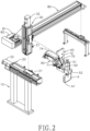
- a pipette-tip connecting device in accordance with the present invention is configured to connect pipette-tips B to tip connectors A1 in a bottom of a pipette A.
- the tip connectors A1 are preferably cylindrical.
- the pipette A may have only one tip connector A1.
- Multiple unused pipette-tips B are orderly arranged in a box.
- the pipette-tips B extend upwards and downwards, and each of the pipette-tips B has a mount opening formed on top thereof.
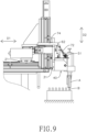
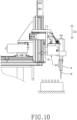
- the pipette-tip connecting device has a base 10, a first positioning mechanism 20, a second positioning mechanism 30, a connecting seat 40, a pipette-fixing seat 50, and a tilt actuator 60.
- the pipette-tip connecting device further has a linkage mechanism 70 and a third positioning mechanism 80.
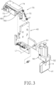
- the first positioning mechanism 20 is mounted on the base 10 and extends along a first direction D1.
- the first direction D1 is preferably horizontal.
- the first positioning mechanism 20 has a first slider 21 and a first actuator 22.
- the first slider 21 is slidable along the first direction D1.
- the first actuator 22 controls a position of the first slider 21 along the first direction D1.
- the first positioning mechanism 20 is a horizontally mounted linear module.
- the first actuator 22 is a motor controlling the first slider 21 via a ball screw of the first positioning mechanism 20.
- the second positioning mechanism 30 is linked to the first slider 21 such that the first positioning mechanism 20 controls a position of the second positioning mechanism 30 along the first direction D1.
- the third positioning mechanism 80 is mounted between the first slider 21 of the first positioning mechanism 20 and the second positioning mechanism 30; that is, the second positioning mechanism 30 is linked to the first slider 21 via the third positioning mechanism 80.
- the third positioning mechanism 80 extends along a third direction D3 and has a third slider 81 and a third actuator 82.
- the third slider 81 is movable along the third direction D3 such that the second positioning mechanism 30 can be aligned with other experiment equipment.
- the second positioning mechanism 30 is omitted, and the second positioning mechanism 30 is directly mounted on the first slider 21.
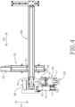
- the second positioning mechanism 30 extends upward and downward along a second direction D2.
- the second direction D2 is preferably vertical, but can be slightly tilted relative to the vertical line.
- the second positioning mechanism 30 has a second slider 31 and a second actuator 32.
- the second slider 31 is slidable upward and downward along the second direction D2.
- the second actuator 32 controls the position of the second slider 31 along the second direction D2.
- the second actuator 32 is preferably a linear module.
- the connecting seat 40 is mounted on the second slider 31 such that the first positioning mechanism 20 and the second positioning mechanism 30 control a position of the connecting seat 40 along the first direction D1 and the second direction D2.
- the pipette-fixing seat 50 is mounted on the connecting seat 40 and is pivotal relative to the connecting seat 40 around an imaginary pivoting axis L1.
- the pipette-fixing seat 50 has a pipette-driving end 51 and a pipette-fixing portion 52.
- the pipette-fixing portion 52 is configured to fix the pipette A.
- the pipette-fixing portion 52 moves in the first direction D1 and the second direction D2 when the pipette-fixing seat 50 pivots relative to the connecting seat 40.
- the pivoting axis L1 is nonparallel to the first direction D1 and the second direction D2, and to be precise, the pivoting axis L1 is perpendicular to the first direction D1 and second direction D2.
- the pipette-driving end 51 is located above the pivoting axis L1.
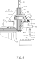
- the tilt actuator 60 is mounted on the connecting seat 40 and controls a relative angle between the pipette-fixing seat 50 and the connecting seat 40.
- the tilt actuator 60 is a linear actuator and has a main body 61 and a driving rod 62.
- the main body 61 is mounted on the connecting seat 40.
- the driving rod 62 is linearly movably mounted in the main body 61. Linear movement of the driving rod 62 controls the relative angle between the pipette-fixing seat 50 and the connecting seat 40.
- the tilt actuator 60 is electrically connected to the first actuator 22 and the second actuator 32 such that when the pipette-fixing seat 50 is being tilted by the tilt actuator 60, the position of the connecting seat 40 in the first direction D1 and the second direction D2 is dynamically compensated by the first actuator 22 and the second actuator 32 to substantially maintain the tip connector A1 of the pipette A in a fixed position.
- the linkage mechanism 70 connects the tilt actuator 60 and the pipette-fixing seat 50 to transform linear motion of the driving rod 62 into rotary motion of the pipette-fixing seat 50.
- the linkage mechanism 70 has a connecting block 71, a connecting bar 72, a guiding seat 73 and a guiding slider 74.
- the connecting block 71 is fixed to the driving rod 62 of the tilt actuator 60.
- Two opposite ends of the connecting bar 72 are a first end and a second end respectively.
- the first end is pivotally connected to the connecting block 71, and the second end is pivotally connected to the pipette-driving end 51 of the pipette-fixing seat 50.
- a relative angle between the connecting bar 72 and the driving rod 62 is preferably from 40 to 60 degrees to ensure that the linear motion of the driving rod 62 can be stably and precisely transformed into the rotary motion of the pipette-fixing seat 50.
- the guiding seat 73 is fixed on the main body 61 of the tilt actuator 60.
- the guiding slider 74 is mounted on the guiding seat 73 and is capable of moving in parallel direction with the driving rod 62.
- the guiding slider 74 is disposed along with the driving rod 62 of the tilt actuator 60.
- the guiding slider 74 is fixed to the connecting block 71 such that when the connecting block 71 is moved by the force of the driving rod 62 and the guiding slider 74 to reduce the angle between the connecting block 71 and the connecting bar 72.
- the tilt actuator 60 is not limited to be connected to the pipette-fixing seat 50 via the linkage mechanism 70.
- the tilt actuator 60 has an output end that controls rotary motion, and said output end is directly connected to the pipette-fixing seat 50 to change the angle between the pipette-fixing seat 50 and the connecting seat 40, and then is able to control the tilting angle of pipette A
- a pipette-tip connecting method in accordance to the present invention comprises the following steps: the first step (S1) is preparation for tip replacement; the second step (S2) is tilted insertion; the third step (S3) is straightened pressing down.
- the pipette-tip connecting method is performed by, but not limited to, the aforementioned pipette-tip connecting device.
- the first step (S1) is preparation for tip replacement.
- the cylindrical tip connectors A1 of the pipette A are protruded from a bottom of the pipette A as aforementioned.
- the first actuator 22 controls the position of the pipette-fixing seat 50 along the first direction D1.
- the second actuator 32 controls upward and downward movement of the pipette-fixing seat 50; that is, the second actuator 32 controls the movement of the pipette-fixing seat 50 along the second direction D2.
- the tilt actuator 60 controls the angle of the pipette-fixing seat 50.
- the pipette-tips B extend upward and downward.
- Each one of the pipette-tips B has the mount opening formed on the top thereof.
- the second step (S2) is tilted insertion.
- the tilt actuator 60 tilts the pipette A such that the centerlines L2 of the tip connectors A1 are tilted relative to the centerlines L3 of the pipette-tips B as shown in Fig. 6 .
- the first actuator 22 aligns distal ends of the tip connectors A1 to the mount openings of the pipette-tips B.
- the first actuator 22 aligns a corner A12 of each one of the tip connectors A1 above the mount opening of a corresponding one of the pipette-tips B, wherein said corner A12 is the portion of a distal end surface A11 and the pipette-tips B are connected primarily.
- the corner A12 forms two right angles.
- the second actuator 32 moves the pipette A downward such that the corners A12 of the tip connectors A1 are able to insert into the pipette-tips via the mount opening and then the second actuator moves continually the pipette downward such that the distal end of the at least one pipette-tip is partially inserted into the pipette-tips B via the mount openings.
- the third step (S3) is straightened pressing down.
- the tilt actuator 60, the first actuator 22, and the second actuator 32 control the pipette A such that the pipette A is rotated with the tip connectors A1 as center of rotation to align the centerlines L2 of each of the tip connectors A1 and match with the centerline L3 of the respective one of the pipette-tips B and to fully insert the distal end surfaces A11 of the tip connectors A1 into the pipette-tips B respectively.
- the second actuator 32 presses down the pipette A such that each of the tip connectors A1 is tightly fitted in the respective one of the pipette-tips B and abuts against an inner annular surface of a respective one of the pipette-tips B to connect the pipette-tips B to the tip connectors A1 correctly and securely.
- the second actuator 32 moves the pipette A upward, and then the pipette A is moved elsewhere to draw and dispense liquid.
- the tilt actuator 60 enables the tip connectors A1 of the pipette A to be inserted into the mount openings of the pipette-tips B in an inclined manner. Therefore, the tip connectors A1 can be inserted into the mount openings as long as the corners A12 are above the mount openings. That is, when viewed laterally as shown in Figs. 5 to 7 , the tip connectors A1 can be successfully inserted into the mount openings as long as each one of the corners A12 is located between the widths of a respective one of the mount openings.
Landscapes
- Physics & Mathematics (AREA)
- Health & Medical Sciences (AREA)
- Life Sciences & Earth Sciences (AREA)
- Chemical & Material Sciences (AREA)
- Analytical Chemistry (AREA)
- Biochemistry (AREA)
- General Health & Medical Sciences (AREA)
- General Physics & Mathematics (AREA)
- Immunology (AREA)
- Pathology (AREA)
- Automatic Analysis And Handling Materials Therefor (AREA)
Claims (5)
- - Verbindungsvorrichtung für Pipettenspitze (B), die konfiguriert ist, um eine Pipettenspitze (B) mit einem Spitzenverbinder (A1) zu verbinden, der aus dem Boden einer Pipette (A) hervorsteht, wobei die Verbindungsvorrichtung für Pipettenspitze (B) Folgendes umfasst:eine Basis (10);einen ersten Positionierungsmechanismus (20), der an der Basis (10) montiert ist und sich entlang einer ersten Richtung (D1) erstreckt; wobei der erste Positionierungsmechanismus (20) Folgendes aufweist:einen ersten Schieber (21), der entlang der ersten Richtung (D1) verschiebbar ist;einen ersten Aktuator (22), der eine Position des ersten Schiebers (21) entlang der ersten Richtung (D1) steuert;einen zweiten Positionierungsmechanismus (30), der mit dem ersten Schieber (21) verbunden ist und sich entlang einer zweiten Richtung (D2) nach oben und nach unten erstreckt; wobei der zweite Positionierungsmechanismus (30) Folgendes aufweist:einen zweiten Schieber (31), der entlang der zweiten Richtung (D2) nach oben und nach unten verschiebbar ist;einen zweiten Aktuator (32), der eine Position des zweiten Schiebers (31) entlang der zweiten Richtung (D2) steuert;einen Verbindungssitz (40), der an dem zweiten Schieber (31) montiert ist;einen Pipettenbefestigungssitz (50), der an dem Verbindungssitz (40) montiert und in Bezug auf den Verbindungssitz (40) um eine imaginäre Schwenkachse (L1) schwenkbar ist; wobei der Pipettenbefestigungssitz (50) Folgendes aufweist:
einen Pipettenbefestigungsabschnitt (52), der von der imaginären Schwenkachse (L1) abweicht, sodass sich der Pipettenbefestigungsabschnitt (52) beim Schwenken des Pipettenbefestigungssitzes (50) entlang einer Kreisbahn um die Schwenkachse (L1) bewegt; wobei die Schwenkachse (L1) nicht parallel zu der ersten Richtung D1 und der zweiten Richtung D2 ist, sodass die Kreisbahn des Pipettenbefestigungsabschnitts (52) Komponenten in der ersten Richtung (D1) und der zweiten Richtung (D2) aufweist; wobei der Pipettenbefestigungsabschnitt (52) konfiguriert ist, um eine Pipette (A) zu befestigen; undeinen Neigungsaktuator (60), der an dem Verbindungssitz (40) montiert ist und einen relativen Winkel zwischen dem Pipettenbefestigungssitz (50) und dem Verbindungssitz (40) steuert; wobei der Neigungsaktuator (60) elektrisch mit dem ersten Aktuator (22) und dem zweiten Aktuator (32) verbunden ist, um den ersten Aktuator (22) zu veranlassen, den Verbindungssitz (40) in der ersten Richtung (D1) zu bewegen, und um den zweiten Aktuator (32) zu veranlassen, den Verbindungssitz (40) in der zweiten Richtung (D2) zu bewegen, um eine Verschiebung des Spitzenverbinders (A1) der Pipette (A) aufgrund des Neigens des Neigungsaktuator (60) zu kompensieren, wodurch die Pipette (A) mit dem mindestens einen Spitzenverbinder (A1) als Drehmitte gedreht wird; wobei der Neigungsaktuator (60) Folgendes aufweisteinen Hauptkörper (61), der an dem Verbindungssitz (40) montiert ist; undeine Antriebsstange (62), die linear bewegbar in dem Hauptkörper (61) montiert ist und den relativen Winkel zwischen dem Pipettenbefestigungssitz (50) und dem Verbindungssitz (40) steuert;einen Verbindungsmechanismus (70), der den Neigungsaktuator (60) und den Pipettenbefestigungssitz (50) verbindet; wobei der Verbindungsmechanismus (70) Folgendes aufweisteinen Verbindungsblock (71), der an der Antriebsstange (62) des Neigungsaktuators (60) befestigt ist, undeine Verbindungsstange (72), die Folgendes aufweistein erstes Ende, das schwenkbar mit dem Verbindungsblock (71) verbunden ist; undein zweites Ende gegenüber dem ersten Ende und das schwenkbar mit dem Pipettenbefestigungssitz (50) verbunden ist. - - Verbindungsvorrichtung für Pipettenspitzen (B) nach Anspruch 1, wobei
der Gestängemechanismus (70) Folgendes aufweist:einen Führungssitz (73), der an dem Hauptkörper (61) des Neigungsaktuators (60) befestigt ist;einen Führungsschieber (74), der an dem Führungssitz (73) montiert ist und in der Lage ist, sich in einer parallelen Richtung mit der Antriebsstange (62) zu bewegen; wobei der Führungsschieber (74) zusammen mit der Antriebsstange (62) des Neigungsaktuators (60) angeordnet ist; wobei der Führungsschieber (74) an dem Verbindungsblock (71) befestigt ist. - - Verbindungsvorrichtung für Pipettenspitzen (B) nach Anspruch 1, wobeider Pipettenbefestigungssitz (50) ein Pipettenantriebsende (51) aufweist, das sich oberhalb der Schwenkachse (L1) befindet;das zweite Ende der Verbindungsstange (72) schwenkbar mit dem Pipettenantriebsende (51) des Pipettenbefestigungssitzes (50) verbunden ist;der relative Winkel zwischen der Verbindungsstange (72) und der Antriebsstange (62) von 40 bis 60 Grad ist.
- - Verbindungsvorrichtung für Pipettenspitzen (B) nach einem der Ansprüche 1 bis 3, die ferner Folgendes umfasst:
einen dritten Positionierungsmechanismus (80), der an dem ersten Schieber (21) des ersten Positionierungsmechanismus (20) montiert ist und sich entlang einer dritten Richtung (D3) erstreckt; wobei der dritte Positionierungsmechanismus (80) Folgendes aufweist:einen dritten Schieber (81), der entlang der dritten Richtung (D3) bewegbar ist, wobei der zweite Positionierungsmechanismus (30) an dem dritten Schieber (81) montiert ist;einen dritten Aktuator (82), der eine Position des dritten Schiebers (81) entlang der dritten Richtung (D3) steuert. - - Verbindungsverfahren für Pipettenspitzen (B) unter Verwendung der Verbindungsvorrichtung für Pipettenspitzen (B) nach Anspruch 1, dadurch gekennzeichnet, dass das Verbindungsverfahren für Pipettenspitzen (B) die folgenden Schritte umfasst:(a) Vorbereitung für den Spitzenersatz: Befestigen der Pipette (A) an dem Pipettenbefestigungssitz (50); wobei der erste Aktuator (22) eine Position des Pipettenbefestigungssitzes (50) entlang der ersten Richtung (D1) steuert; der zweite Aktuator (32) eine Aufwärts- und Abwärtsbewegung des Pipettenbefestigungssitzes (50) steuert; der Neigungsaktuator (60) einen Winkel des Pipettenbefestigungssitzes (50) steuert; Vorbereiten mindestens einer Pipettenspitze (B); wobei sich die mindestens eine Pipettenspitze (B) nach oben und nach unten erstreckt; jede der mindestens einen Pipettenspitze (B) eine Montageöffnung aufweist, die an einer Oberseite davon gebildet ist;(b) geneigte Einführung: der Neigungsaktuator (60) neigt die Pipette (A) sodass eine Mittellinie (L2) von jedem des mindestens einen Spitzenverbinders (A1) in Bezug auf eine Mittellinie (L3) von jeder der mindestens einen Pipettenspitze (B) geneigt wird; wobei der erste Aktuator (22) ein distales Ende von jedem des mindestens einen Spitzenverbinders (A1) auf die Befestigungsöffnung einer jeweiligen der mindestens einen Pipettenspitze (B) ausrichtet, und dann der zweite Aktuator (32) die Pipette (A) nach unten bewegt, sodass das distale Ende von jedem des mindestens einen Spitzenverbinders (A1) über die Befestigungsöffnung teilweise in die jeweilige der mindestens einen Pipettenspitze (B) eingeführt wird;(c) gerades Abwärtsdrücken: der Neigungsaktuator (60), der erste Aktuator (22) und der zweite Aktuator (32) steuern die Pipette (A), sodass die Pipette (A) mit dem mindestens einen Spitzenverbinder (A1) als Drehpunkt gedreht wird, um die Mittellinie (L2) von jedem des mindestens einen Spitzenverbinders (A1) mit der Mittellinie (L3) der jeweiligen der mindestens einen Pipettenspitze (B) auszurichten und das distale Ende des mindestens einen Spitzenverbinders (A1) vollständig in die Pipettenspitze (B) einzuführen; dann drückt der zweite Aktuator (32) die Pipette (A) nach unten, sodass jeder des mindestens einen Spitzenverbinder (A1) fest in die jeweilige der mindestens einen Pipettenspitze (B) eingepasst ist.
Priority Applications (1)
| Application Number | Priority Date | Filing Date | Title |
|---|---|---|---|
| EP21205921.6A EP4075147B1 (de) | 2021-11-02 | 2021-11-02 | Pipettenspitzenverbindungsvorrichtung und verfahren dafür |
Applications Claiming Priority (1)
| Application Number | Priority Date | Filing Date | Title |
|---|---|---|---|
| EP21205921.6A EP4075147B1 (de) | 2021-11-02 | 2021-11-02 | Pipettenspitzenverbindungsvorrichtung und verfahren dafür |
Publications (3)
| Publication Number | Publication Date |
|---|---|
| EP4075147A1 EP4075147A1 (de) | 2022-10-19 |
| EP4075147B1 true EP4075147B1 (de) | 2025-01-15 |
| EP4075147C0 EP4075147C0 (de) | 2025-01-15 |
Family
ID=78770338
Family Applications (1)
| Application Number | Title | Priority Date | Filing Date |
|---|---|---|---|
| EP21205921.6A Active EP4075147B1 (de) | 2021-11-02 | 2021-11-02 | Pipettenspitzenverbindungsvorrichtung und verfahren dafür |
Country Status (1)
| Country | Link |
|---|---|
| EP (1) | EP4075147B1 (de) |
Families Citing this family (1)
| Publication number | Priority date | Publication date | Assignee | Title |
|---|---|---|---|---|
| WO2024135281A1 (ja) * | 2022-12-22 | 2024-06-27 | 株式会社日立ハイテク | 自動分析装置 |
Family Cites Families (3)
| Publication number | Priority date | Publication date | Assignee | Title |
|---|---|---|---|---|
| CA3019789C (en) * | 2016-04-22 | 2025-11-18 | Becton, Dickinson And Company | AUTOMATED DIAGNOSTIC ANALYZER AND ITS OPERATING PROCESS |
| US11167282B2 (en) * | 2017-01-31 | 2021-11-09 | HighRes Biosolutions, Inc. | Auto-pipetting apparatus and method |
| CN110383034B (zh) * | 2017-03-09 | 2022-07-12 | 霍罗杰克股份有限公司 | 自动化制备生物样本的系统及方法 |
-
2021
- 2021-11-02 EP EP21205921.6A patent/EP4075147B1/de active Active
Also Published As
| Publication number | Publication date |
|---|---|
| EP4075147C0 (de) | 2025-01-15 |
| EP4075147A1 (de) | 2022-10-19 |
Similar Documents
| Publication | Publication Date | Title |
|---|---|---|
| US9132428B2 (en) | Positioning device for a sample carrier | |
| EP4075147B1 (de) | Pipettenspitzenverbindungsvorrichtung und verfahren dafür | |
| EP3057392B1 (de) | Saugdüse und komponentenmontagevorrichtung | |
| WO2017082428A1 (ja) | スクリーン印刷方法およびその装置 | |
| CN102159327B (zh) | 喷嘴位置修正机构以及具备该机构的涂布装置 | |
| US6283681B1 (en) | Method and device for aligning a workpiece on a machine tool table | |
| CN210058797U (zh) | 自动组装设备 | |
| US20250044315A1 (en) | Pipette-tip connecting method | |
| CN115970782B (zh) | 吸液器的吸管尖连接装置及连接方法 | |
| EP1786073B1 (de) | Anordung zur Einstellung der Crimphöhe | |
| JP7208337B1 (ja) | 分注器用フィットチップ連結装置及びその連結方法 | |
| US12290805B2 (en) | Multichannel pipetting head | |
| CN219173566U (zh) | 一种料盘的定位机构 | |
| TWI804974B (zh) | 吸液器的吸管尖連接裝置及連接方法 | |
| KR102423703B1 (ko) | 밀핀 가공용 고정 지그 | |
| CN117549055A (zh) | 一种工件位置修正方法 | |
| JP2021124510A (ja) | 自動液体処理用途のための調節可能なマウント | |
| CN220168306U (zh) | 一种转接组件以及医疗器械 | |
| CN219837671U (zh) | 柔性自动线用以平面为基准的阀套零件角向预定位夹具 | |
| CN221607093U (zh) | 一种调节结构及拾取装置 | |
| CN219837669U (zh) | 柔性自动线用以径向孔为基准的阀套零件角向预定位夹具 | |
| CN223615929U (zh) | 间距调节装置和移液设备 | |
| CN223455381U (zh) | 一种锥桶焊接工装 | |
| CN114603293A (zh) | 焊头自动更换装置、焊头更换方法 | |
| WO2025134673A1 (ja) | 自動分析装置 |
Legal Events
| Date | Code | Title | Description |
|---|---|---|---|
| PUAI | Public reference made under article 153(3) epc to a published international application that has entered the european phase |
Free format text: ORIGINAL CODE: 0009012 |
|
| STAA | Information on the status of an ep patent application or granted ep patent |
Free format text: STATUS: THE APPLICATION HAS BEEN PUBLISHED |
|
| STAA | Information on the status of an ep patent application or granted ep patent |
Free format text: STATUS: REQUEST FOR EXAMINATION WAS MADE |
|
| AK | Designated contracting states |
Kind code of ref document: A1 Designated state(s): AL AT BE BG CH CY CZ DE DK EE ES FI FR GB GR HR HU IE IS IT LI LT LU LV MC MK MT NL NO PL PT RO RS SE SI SK SM TR |
|
| 17P | Request for examination filed |
Effective date: 20221013 |
|
| RBV | Designated contracting states (corrected) |
Designated state(s): AL AT BE BG CH CY CZ DE DK EE ES FI FR GB GR HR HU IE IS IT LI LT LU LV MC MK MT NL NO PL PT RO RS SE SI SK SM TR |
|
| GRAP | Despatch of communication of intention to grant a patent |
Free format text: ORIGINAL CODE: EPIDOSNIGR1 |
|
| STAA | Information on the status of an ep patent application or granted ep patent |
Free format text: STATUS: GRANT OF PATENT IS INTENDED |
|
| RIC1 | Information provided on ipc code assigned before grant |
Ipc: G01N 35/04 20060101ALN20240719BHEP Ipc: G01N 35/10 20060101AFI20240719BHEP |
|
| INTG | Intention to grant announced |
Effective date: 20240808 |
|
| GRAS | Grant fee paid |
Free format text: ORIGINAL CODE: EPIDOSNIGR3 |
|
| GRAA | (expected) grant |
Free format text: ORIGINAL CODE: 0009210 |
|
| STAA | Information on the status of an ep patent application or granted ep patent |
Free format text: STATUS: THE PATENT HAS BEEN GRANTED |
|
| AK | Designated contracting states |
Kind code of ref document: B1 Designated state(s): AL AT BE BG CH CY CZ DE DK EE ES FI FR GB GR HR HU IE IS IT LI LT LU LV MC MK MT NL NO PL PT RO RS SE SI SK SM TR |
|
| REG | Reference to a national code |
Ref country code: CH Ref legal event code: EP Ref country code: GB Ref legal event code: FG4D |
|
| REG | Reference to a national code |
Ref country code: DE Ref legal event code: R096 Ref document number: 602021024916 Country of ref document: DE |
|
| REG | Reference to a national code |
Ref country code: IE Ref legal event code: FG4D |
|
| U01 | Request for unitary effect filed |
Effective date: 20250210 |
|
| U07 | Unitary effect registered |
Designated state(s): AT BE BG DE DK EE FI FR IT LT LU LV MT NL PT RO SE SI Effective date: 20250217 |
|
| PG25 | Lapsed in a contracting state [announced via postgrant information from national office to epo] |
Ref country code: RS Free format text: LAPSE BECAUSE OF FAILURE TO SUBMIT A TRANSLATION OF THE DESCRIPTION OR TO PAY THE FEE WITHIN THE PRESCRIBED TIME-LIMIT Effective date: 20250415 |
|
| PG25 | Lapsed in a contracting state [announced via postgrant information from national office to epo] |
Ref country code: PL Free format text: LAPSE BECAUSE OF FAILURE TO SUBMIT A TRANSLATION OF THE DESCRIPTION OR TO PAY THE FEE WITHIN THE PRESCRIBED TIME-LIMIT Effective date: 20250115 |
|
| PG25 | Lapsed in a contracting state [announced via postgrant information from national office to epo] |
Ref country code: ES Free format text: LAPSE BECAUSE OF FAILURE TO SUBMIT A TRANSLATION OF THE DESCRIPTION OR TO PAY THE FEE WITHIN THE PRESCRIBED TIME-LIMIT Effective date: 20250115 |
|
| PG25 | Lapsed in a contracting state [announced via postgrant information from national office to epo] |
Ref country code: IS Free format text: LAPSE BECAUSE OF FAILURE TO SUBMIT A TRANSLATION OF THE DESCRIPTION OR TO PAY THE FEE WITHIN THE PRESCRIBED TIME-LIMIT Effective date: 20250515 Ref country code: NO Free format text: LAPSE BECAUSE OF FAILURE TO SUBMIT A TRANSLATION OF THE DESCRIPTION OR TO PAY THE FEE WITHIN THE PRESCRIBED TIME-LIMIT Effective date: 20250415 |
|
| PG25 | Lapsed in a contracting state [announced via postgrant information from national office to epo] |
Ref country code: HR Free format text: LAPSE BECAUSE OF FAILURE TO SUBMIT A TRANSLATION OF THE DESCRIPTION OR TO PAY THE FEE WITHIN THE PRESCRIBED TIME-LIMIT Effective date: 20250115 |
|
| PG25 | Lapsed in a contracting state [announced via postgrant information from national office to epo] |
Ref country code: GR Free format text: LAPSE BECAUSE OF FAILURE TO SUBMIT A TRANSLATION OF THE DESCRIPTION OR TO PAY THE FEE WITHIN THE PRESCRIBED TIME-LIMIT Effective date: 20250416 |
|
| PG25 | Lapsed in a contracting state [announced via postgrant information from national office to epo] |
Ref country code: SM Free format text: LAPSE BECAUSE OF FAILURE TO SUBMIT A TRANSLATION OF THE DESCRIPTION OR TO PAY THE FEE WITHIN THE PRESCRIBED TIME-LIMIT Effective date: 20250115 |
|
| PG25 | Lapsed in a contracting state [announced via postgrant information from national office to epo] |
Ref country code: CZ Free format text: LAPSE BECAUSE OF FAILURE TO SUBMIT A TRANSLATION OF THE DESCRIPTION OR TO PAY THE FEE WITHIN THE PRESCRIBED TIME-LIMIT Effective date: 20250115 |
|
| PG25 | Lapsed in a contracting state [announced via postgrant information from national office to epo] |
Ref country code: SK Free format text: LAPSE BECAUSE OF FAILURE TO SUBMIT A TRANSLATION OF THE DESCRIPTION OR TO PAY THE FEE WITHIN THE PRESCRIBED TIME-LIMIT Effective date: 20250115 |
|
| PLBE | No opposition filed within time limit |
Free format text: ORIGINAL CODE: 0009261 |
|
| STAA | Information on the status of an ep patent application or granted ep patent |
Free format text: STATUS: NO OPPOSITION FILED WITHIN TIME LIMIT |
|
| REG | Reference to a national code |
Ref country code: CH Ref legal event code: L10 Free format text: ST27 STATUS EVENT CODE: U-0-0-L10-L00 (AS PROVIDED BY THE NATIONAL OFFICE) Effective date: 20251126 |
|
| REG | Reference to a national code |
Ref country code: CH Ref legal event code: U11 Free format text: ST27 STATUS EVENT CODE: U-0-0-U10-U11 (AS PROVIDED BY THE NATIONAL OFFICE) Effective date: 20251201 |
|
| U20 | Renewal fee for the european patent with unitary effect paid |
Year of fee payment: 5 Effective date: 20251030 |
|
| 26N | No opposition filed |
Effective date: 20251016 |
|
| PGFP | Annual fee paid to national office [announced via postgrant information from national office to epo] |
Ref country code: GB Payment date: 20251015 Year of fee payment: 5 |
|
| PGFP | Annual fee paid to national office [announced via postgrant information from national office to epo] |
Ref country code: CH Payment date: 20251201 Year of fee payment: 5 |