EP4074983B1 - Hydraulisches aggregat und vorrichtung mit dem aggregat - Google Patents
Hydraulisches aggregat und vorrichtung mit dem aggregat Download PDFInfo
- Publication number
- EP4074983B1 EP4074983B1 EP22167615.8A EP22167615A EP4074983B1 EP 4074983 B1 EP4074983 B1 EP 4074983B1 EP 22167615 A EP22167615 A EP 22167615A EP 4074983 B1 EP4074983 B1 EP 4074983B1
- Authority
- EP
- European Patent Office
- Prior art keywords
- hydraulic
- drive unit
- support frame
- tank
- hydraulic tank
- Prior art date
- Legal status (The legal status is an assumption and is not a legal conclusion. Google has not performed a legal analysis and makes no representation as to the accuracy of the status listed.)
- Active
Links
Images


Classifications
-
- F—MECHANICAL ENGINEERING; LIGHTING; HEATING; WEAPONS; BLASTING
- F15—FLUID-PRESSURE ACTUATORS; HYDRAULICS OR PNEUMATICS IN GENERAL
- F15B—SYSTEMS ACTING BY MEANS OF FLUIDS IN GENERAL; FLUID-PRESSURE ACTUATORS, e.g. SERVOMOTORS; DETAILS OF FLUID-PRESSURE SYSTEMS, NOT OTHERWISE PROVIDED FOR
- F15B1/00—Installations or systems with accumulators; Supply reservoir or sump assemblies
- F15B1/26—Supply reservoir or sump assemblies
-
- B—PERFORMING OPERATIONS; TRANSPORTING
- B30—PRESSES
- B30B—PRESSES IN GENERAL
- B30B15/00—Details of, or accessories for, presses; Auxiliary measures in connection with pressing
- B30B15/16—Control arrangements for fluid-driven presses
-
- F—MECHANICAL ENGINEERING; LIGHTING; HEATING; WEAPONS; BLASTING
- F04—POSITIVE - DISPLACEMENT MACHINES FOR LIQUIDS; PUMPS FOR LIQUIDS OR ELASTIC FLUIDS
- F04B—POSITIVE-DISPLACEMENT MACHINES FOR LIQUIDS; PUMPS
- F04B23/00—Pumping installations or systems
- F04B23/02—Pumping installations or systems having reservoirs
- F04B23/025—Pumping installations or systems having reservoirs the pump being located directly adjacent the reservoir
- F04B23/028—Pumping installations or systems having reservoirs the pump being located directly adjacent the reservoir the pump being mounted on top of the reservoir
-
- F—MECHANICAL ENGINEERING; LIGHTING; HEATING; WEAPONS; BLASTING
- F04—POSITIVE - DISPLACEMENT MACHINES FOR LIQUIDS; PUMPS FOR LIQUIDS OR ELASTIC FLUIDS
- F04B—POSITIVE-DISPLACEMENT MACHINES FOR LIQUIDS; PUMPS
- F04B53/00—Component parts, details or accessories not provided for in, or of interest apart from, groups F04B1/00 - F04B23/00 or F04B39/00 - F04B47/00
- F04B53/16—Casings; Cylinders; Cylinder liners or heads; Fluid connections
-
- F—MECHANICAL ENGINEERING; LIGHTING; HEATING; WEAPONS; BLASTING
- F15—FLUID-PRESSURE ACTUATORS; HYDRAULICS OR PNEUMATICS IN GENERAL
- F15B—SYSTEMS ACTING BY MEANS OF FLUIDS IN GENERAL; FLUID-PRESSURE ACTUATORS, e.g. SERVOMOTORS; DETAILS OF FLUID-PRESSURE SYSTEMS, NOT OTHERWISE PROVIDED FOR
- F15B2211/00—Circuits for servomotor systems
- F15B2211/20—Fluid pressure source, e.g. accumulator or variable axial piston pump
- F15B2211/205—Systems with pumps
- F15B2211/20507—Type of prime mover
- F15B2211/20515—Electric motor
-
- F—MECHANICAL ENGINEERING; LIGHTING; HEATING; WEAPONS; BLASTING
- F15—FLUID-PRESSURE ACTUATORS; HYDRAULICS OR PNEUMATICS IN GENERAL
- F15B—SYSTEMS ACTING BY MEANS OF FLUIDS IN GENERAL; FLUID-PRESSURE ACTUATORS, e.g. SERVOMOTORS; DETAILS OF FLUID-PRESSURE SYSTEMS, NOT OTHERWISE PROVIDED FOR
- F15B2211/00—Circuits for servomotor systems
- F15B2211/20—Fluid pressure source, e.g. accumulator or variable axial piston pump
- F15B2211/205—Systems with pumps
- F15B2211/2053—Type of pump
Definitions
- the invention relates to a hydraulic unit, in particular a drive unit according to the preamble of claim 1. Furthermore, the invention relates to a device with the hydraulic drive unit and a machine housing.
- a hydraulic drive unit is disclosed. This has a tank for oil, to which a hydraulic block is attached on the side. The hydraulic block is fluidically connected to the tank. Further constructions relevant for the evaluation of the invention can be found in the JP S49 95392 U , the US 2004/134189 A1 , the EP 2 251 191 A1 and the JP S56 148101 U7 . The most likely JP S49 101186 U discloses a drive unit with the features listed in the preamble of claim 1.
- the invention is based on the object of creating a hydraulic drive unit that is designed to be simple and cost-effective in terms of device technology and can be used flexibly. Furthermore, the object of the invention is to create a device with a machine housing and a hydraulic drive unit that is designed to be simple and cost-effective in terms of device technology and can be used flexibly.
- a hydraulic drive unit with a hydraulic control is provided. Furthermore, the drive unit has a hydraulic tank, which is preferably fluidically connected to the control. In addition, the drive unit has a support frame. According to the invention, the hydraulic tank is mounted under the support frame and the hydraulic control is installed on the support frame.
- This solution has the advantage that the support frame bears the load of the control system.
- the mechanical requirements for the hydraulic tank are therefore comparatively low compared to the state of the art. It is no longer necessary to design the hydraulic tank in such a way that it has to support a control system.
- Another advantage is that the arrangement of the hydraulic tank under the support frame means that it is protected by the support frame.
- the hydraulic tank from the state of the art explained at the beginning serves as a load-bearing element for a hydraulic block with valves, a drive unit and other components.
- the hydraulic tank is made of plastic, which means that it can be a plastic container.
- plastic which means that it can be a plastic container.
- the hydraulic tank can be manufactured cost-effectively. Materials such as die-cast aluminum or a welded sheet metal construction are no longer absolutely necessary, since the hydraulic tank no longer has to bear the load of the hydraulic control.
- the hydraulic tank can be manufactured cost-effectively by rotational molding. This also enables a flexible design of the hydraulic tank, so that flow optimization and degassing optimization are easily possible.
- the hydraulic tank and the control system are arranged one above the other, which results in a compact design and enables easy machine integration into a device such as a hydraulic press brake.
- the hydraulic tank preferably has a geometry that is optimized for flow and/or degassing.
- a return opening can be separated from a suction opening by a wall.
- the hydraulic tank has a U-shaped flow space, whereby the flow space is preferably designed as a horizontal U. In a first space leg of the flow space, the return opening and the suction opening can open into a second space leg of the flow space.
- the control system has a hydraulic block.
- This has, for example, at least one integrated hydraulic channel and/or at least one built-on and/or integrated valve.
- the assembly of the comparatively heavy hydraulic block on the support frame above the hydraulic tank is particularly advantageous because the hydraulic tank is relieved of the weight of the hydraulic block.
- the hydraulic block is, for example, manufactured in a simple manner using a 3D printing process, in particular using a 3D sand core printing process. This also makes it possible to design the at least one hydraulic channel flexibly.
- the hydraulic block can thus be made compact overall, making the hydraulic drive unit more compact overall.
- the flexible design of the at least one hydraulic channel and also of hydraulic connections makes it possible, for example, to arrange hydraulic interfaces or machine interfaces on the top of the hydraulic block, making them easily accessible.
- the hydraulic block can be manufactured in a simple manner using the 3D printing process in such a way that it can be arranged above the hydraulic tank on the support frame with little effort in terms of device technology. It is also conceivable to design the interfaces of the hydraulic block symmetrically, so that, for example, when using the hydraulic drive unit in a press brake, only one variant of the hydraulic drive unit is necessary for a left and right press cylinder.
- both the tank and the control system are easier to access, for example for maintenance or in the event of a service.
- the hydraulic block By arranging the control with the hydraulic block on or above the hydraulic tank, the hydraulic block can have a symmetrical design, particularly with regard to a customer interface or hydraulic interface. This is possible because the interface to the hydraulic tank can be designed below the hydraulic block and thus above the hydraulic tank.
- the support frame is designed as a support plate.
- the support plate is designed in such a way that it can support the load taken up by the control and the hydraulic tank on a statically load-bearing support surface.
- a machine element or a floor can in particular serve as the support surface.
- the support surface is, for example, below the control and/or below the hydraulic tank, whereby the control and/or the hydraulic tank is/are easily accessible.
- the support plate is designed to be folded.
- the hydraulic tank and/or the control is connected to the support frame via connecting elements, in particular via a screw connection.
- the hydraulic tank can be screwed to the folded support plate from below and the hydraulic block of the control from above.
- the support plate can divert or support the load on a statically load-bearing machine element on the underside of the hydraulic block.
- the support frame has a flange section for fastening the hydraulic tank and for fastening the control.
- the control can be fastened to an upper flange surface or top side of the flange section.
- the hydraulic tank can be fastened to a lower flange surface or bottom side of the flange section.
- the flange section is preferably designed in the shape of a frame. Further preferably, it can be provided alternatively or additionally that the control is fastened to the flange section further inside than the hydraulic tank.
- the flange surfaces are preferably designed to be level or flat.
- the support frame has lateral, flat support sections that extend laterally away from the flange section.
- the support sections can overlap the hydraulic tank and rest on the support surface.
- the hydraulic tank can thus be arranged between the support sections, whereby these offer additional protection against external forces.
- the support sections extend approximately parallel to one another or parallel to one another. It would be conceivable to design the support frame in such a way that the hydraulic tank is accommodated between the support sections and can be easily inserted and removed between them, for example for assembly and disassembly.
- the support frame can thus have a protected slot for the hydraulic tank.
- the support frame preferably has a U-shaped base body which has two support legs and a connecting leg, wherein the connecting leg can be designed as a flange section.
- the flange section can have a through-opening through which the control lines can be inserted into the tank.
- the through-opening is preferably above a tank opening of the hydraulic tank.
- the tank opening can, for example, be designed in such a way that the two space legs can be reached through it. The lines can thus simply be introduced into a respective space leg in order to supply and discharge pressure medium.
- a sealing element can advantageously be arranged between the control and the support frame.
- the sealing element is provided between the hydraulic block and the flange section.
- the sealing element is, for example, arranged in a ring shape and circumferentially around the through-opening on the upper flange surface of the flange section.
- the hydraulic block can accordingly have a contact surface, with the sealing element then preferably being arranged between the contact surface and the upper flange surface.
- a sealing element between the hydraulic tank and the support frame.
- the sealing element can be designed in a ring shape and runs all the way around the tank opening. It can also be provided all the way around the through-opening, preferably on the lower flange surface of the flange section.
- the hydraulic tank preferably has an upper contact surface, which preferably surrounds the tank opening and rests on the lower flange surface via the sealing element.
- a sealing element can be arranged between the sheet metal and the hydraulic block, and a sealing element can be arranged between the sheet metal and the hydraulic tank.
- the arrangement of the tank opening below the through opening of the support frame is advantageous because the openings are preferably above the oil level in the hydraulic tank.
- the hydraulic tank is preferably connected to the support structure via sealing surfaces, which are also above the oil level. This type of configuration and arrangement creates an extremely robust design.
- the support frame preferably has leveling feet.
- the support frame can be supported on the support surface using these.
- Each leveling foot also has a respective damping base. This can be firmly connected to the respective leveling foot. It is also conceivable that at least some of the leveling feet or a respective leveling foot can be adjusted relative to the support frame.
- each leveling foot has a plate that is connected to the support frame using a screw bolt. The leveling foot can then be adjusted axially using the screw bolt.
- the folded sheet metal has leveling feet with a damping base connected to the underside.
- the hydraulic tank is preferably supported on the top of the support frame and is designed in such a way that it can be supported on the support surface at the bottom and/or on the side. This means that the tank can also rest on the load-bearing machine element, for example. The entire load of the hydraulic tank is therefore not borne by the support frame, which means that it can be designed more simply.
- the control unit can then advantageously be attached to a drive unit.
- This is preferably fluidically connected to the control unit.
- the drive unit has, for example, an electric motor and a hydraulic machine, in particular a hydraulic pump.
- the hydraulic machine can be driven by the electric motor.
- the hydraulic machine preferably has two connections, in particular a pressure connection or tank connection or two pressure connections. The two connections can then preferably be fluidically connected to the hydraulic block.
- the drive unit can be installed on and/or at least partially in the hydraulic block, which makes the drive unit extremely compact.
- control system has lines for fluidic connection to the hydraulic tank.
- the lines can be attached to the control system and cantilever into one or the tank opening of the hydraulic tank via the support frame.
- the lines can thus be mechanically decoupled from the hydraulic tank and preferably only fluidic connected to it in the This allows for simple design and assembly.
- hydraulic lines and/or channels can extend from the hydraulic block through one or the through-opening of the support frame and one or the tank opening of the hydraulic tank.
- the lines preferably protrude freely into the hydraulic tank.
- the tank opening is also preferably formed at the top of the hydraulic tank. It would be conceivable to connect the lines mechanically to the hydraulic tank in order to dampen vibrations in the lines, for example. However, this would not require a sealing connection, as is the case with a connecting connection.
- the sealing connection can be formed between the hydraulic block and the support frame.
- a device in particular a hydraulic press brake, is provided with a machine housing.
- the device can have a drive unit according to one or more of the preceding aspects.
- the machine housing has, for example, two housing walls, in particular extending from top to bottom. These can be connected via at least one connecting profile arranged between them.
- the connecting profile can have the support surface. Alternatively, it is conceivable to form the support surface adjacent to or adjacent to the connecting profile.
- the drive unit is then preferably arranged on the support surface. Due to the compact drive unit, the hydraulic block of which is flexibly accessible from all sides and from above, since the hydraulic tank is arranged under the hydraulic block, it can be flexibly arranged in the machine housing. It would also be conceivable to provide at least two drive units in the device. These can be designed the same at least with regard to their connections or overall.
- the drive unit is also preferably integrated in the connecting profile, whereby the drive unit can be additionally protected from mechanical influences by the connecting profile.
- the connecting profile has, for example, a U- or H-shaped cross-section.
- the support surface can then be provided between the legs of the connecting profile.
- the drive unit can thus be arranged, for example, between the legs. It is also conceivable that the housing walls extend parallel to one another.
- the drive unit or the proportions of the drive unit are designed in such a way that it can be used with only one variant in front of, on, can be arranged behind or in a connecting element or connecting profile between machine cheeks or housing walls.
- the unit according to the invention allows, for example, the heavy hydraulic block to be easily mounted above the hydraulic tank, in particular in the form of a plastic container. This means that a sealing point from the hydraulic block to the hydraulic tank can be located above the oil level, which reduces the risk of leakage over the service life.
- the advantageous arrangement of the hydraulic block allows an interface to a device, such as a press brake, to be flexibly formed.
- the hydraulic block or the control system are easily accessible for maintenance or for servicing, for example to replace hydraulic components. This is made possible by the fact that the hydraulic block is provided on the top of the drive unit.
- a hydraulic drive unit which is made up of a plastic container and a support frame.
- the plastic container is mounted under the support frame.
- a hydraulic control system is mounted on the support frame.
- the support frame can take the load of the structures. Alternatively or additionally, the support frame can have a protected slot for the plastic container. Furthermore, alternatively or additionally, the support frame can relieve the plastic container of forces which may be introduced by connecting lines of the control system.
- a hydraulic drive unit 1 is shown.
- This has a hydraulic control 2 which is attached to a support frame 4.
- a hydraulic tank 6 is provided under the support frame 4, which is also connected to the support frame 4.
- the control 2 has a hydraulic block 8.
- This has connections 10 which are accessible from above.
- the connections 10 are designed symmetrically, which means that the unit 1 can be used flexibly, as explained in more detail above.
- the hydraulic block 8 has integrated hydraulic channels.
- a large number of valves 12 are built onto and/or integrated into the hydraulic block 8. Further preferably, the valves 12 or at least some of the valves 12 are provided on an upper side of the hydraulic block 8, whereby they are easily accessible.
- the support frame 4 allows the hydraulic tank 6 to be arranged below the hydraulic block 8 or below the control 2.
- the control 2 is thus fully accessible from the side and from above.
- the unit 1 can thus be easily assembled and connected to hydraulic components and also has easy accessibility for service or maintenance purposes.
- a hydraulic machine 14 and an electric motor 16 that drives the hydraulic machine 14 can be seen next to the hydraulic block 8.
- the hydraulic machine 14 is attached to the side of the hydraulic block 8 and is fluidically connected to it.
- the hydraulic machine 14 is arranged above the hydraulic tank 6.
- the electric motor 16 is connected to the hydraulic machine 14 and extends away from the hydraulic tank 6 at a parallel distance.
- the hydraulic machine 14 is thus arranged between the hydraulic block 8 and the electric motor 16.
- the hydraulic machine 14 and the electric motor 16 form a rod-shaped or elongated unit that extends laterally from the hydraulic block 8 over the hydraulic tank 6. It is also conceivable to integrate the hydraulic machine 14 or at least a drive unit of the hydraulic machine 14 in the hydraulic block 8.
- the support frame 4 has a flange section 18 to which the hydraulic block 8 and the hydraulic tank 6 are attached.
- Two lateral flat support sections 20 and 22 extend laterally from the flange section 18.
- the hydraulic tank 6 is arranged between these.
- Each support section 20 and 22 has two leveling feet 24 and 26, of which for the sake of simplicity only two are provided with a reference number.
- the support frame 4 is supported on a support surface via these.
- the hydraulic tank 6 has an upper flange section 30.
- This is designed in the shape of a frame and delimits a tank opening 32.
- the flange section 30 rests with an upper flange surface on the flange section 18 of the support frame 4 via an annular sealing element that extends continuously around the flange section 30.
- the flange section 30 is designed in such a way that it can receive screws 36 of the screw connection 28, see Figure 2 , can accommodate.
- the flange section 30 has, for example, inserts with an internal thread, such as nuts.
- the inner tank space of the hydraulic tank 6 can be seen, in which a cross-sectional view from below through the hydraulic tank 6 is shown.
- the hydraulic tank 6 has a U-shaped tank space 46, which is designed horizontally.
- two space legs 48 and 50 of the U-shaped tank space 46 extend approximately in a direction transverse to a top-bottom direction.
- the line 44 flows into the space leg 48.
- the frame-shaped design of the flange section 30 of the hydraulic tank 6 can be seen.
- the frame-shaped design of the flange connection 52 between the support frame 4 and the hydraulic block 8 can also be seen.
- a further line 54 extends from the hydraulic block 8 into the space leg 50 of the hydraulic tank 6. This serves to remove oil from the hydraulic tank 6.
- the tank space 46 is easily accessible via the through opening 40 and the tank opening 32.
- the leveling foot 24 is shown. This has a plate 56 on the bottom with a damping base 58 between the plate 56 and a support surface 60.
- a screw bolt 60 extends upwards from the plate 56 and is screwed to the support frame 4.
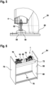
- a device 64 is shown. This is part of a hydraulic press brake.
- the device 64 has a machine housing 66. This has two plate-shaped housing walls 68 and 70. These extend are parallel to one another and in an up-down direction.
- Three connecting profiles 72, 74 and 76 are arranged between the housing walls 68, 70 in order to connect the housing walls 68, 70 to one another.
- the upper connecting profile 72 is U-shaped. Legs of the U-shaped connecting profile 72 extend upwards so that a space accessible from above is delimited by the connecting profile 72.
- the connecting web of the connecting profile 72 between the legs has the support surface 60, by means of which the hydraulic unit 1 and an identically constructed hydraulic unit 78 are supported. The units 1 and 78 point towards one another with their electric motors 16.
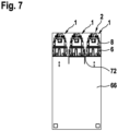
- FIG. 7 a cross section through the machine housing 66 is shown.
- Various possible positions of the hydraulic unit 1 are shown schematically. This can be according to Figure 6 be arranged in the connecting profile 72 or to the side of it if a corresponding support surface is formed.
- the arrangement of the hydraulic block 8 or the control 2 above the hydraulic tank 6 enables such a flexible arrangement, since the control 2 is accessible from the side and from above.
Landscapes
- Engineering & Computer Science (AREA)
- Mechanical Engineering (AREA)
- General Engineering & Computer Science (AREA)
- Physics & Mathematics (AREA)
- Fluid Mechanics (AREA)
- Supply Devices, Intensifiers, Converters, And Telemotors (AREA)
Description
- Die Erfindung betrifft ein hydraulisches Aggregat, insbesondere ein Antriebsaggregat gemäß dem Oberbegriff des Anspruchs 1. Außerdem betrifft die Erfindung eine Vorrichtung mit dem hydraulischen Antriebsaggregat und einem Maschinengehäuse.
- Aus der
DE 10 2018 218 113 A1 ist ein hydraulisches Antriebsaggregat offenbart. Dieses hat einen Tank für Öl, an dem seitlich ein Hydraulikblock befestigt ist. Der Hydraulikblock ist fluidisch mit dem Tank verbunden. Weitere für die Bewertung der Erfindung relevante Konstruktionen finden sich in derJP S49 95392 U US 2004/134189 A1 , derEP 2 251 191 A1 und derJP S56 148101 U7 JP S49 101186 U - Demgegenüber liegt der Erfindung die Aufgabe zugrunde, ein hydraulisches Antriebsaggregat zu schaffen, das vorrichtungstechnisch einfach und kostengünstig ausgestaltet und flexibel einsetzbar ist. Außerdem ist es die Aufgabe der Erfindung, eine Vorrichtung mit einem Maschinengehäuse und einem hydraulischen Antriebsaggregat zu schaffen, die vorrichtungstechnisch einfach und kostengünstig ausgestaltet und flexibel einsetzbar ist
- Diese Aufgabe hinsichtlich des hydraulischen Antriebsaggregats wird gelöst gemäß den Merkmalen des Anspruchs 1 und hinsichtlich der Vorrichtung gemäß den Merkmalen des Anspruchs 12.
- Vorteilhafte Weiterbildungen der Erfindung sind Gegenstand der Unteransprüche.
- Erfindungsgemäß ist ein hydraulisches Antriebsaggregat mit einer hydraulischen Steuerung vorgesehen. Des Weiteren weist das Antriebsaggregat einen Hydrauliktank auf, der vorzugsweise mit der Steuerung fluidisch verbunden ist. Außerdem hat das Antriebsaggregat ein Trägergestell. Erfindungsgemäß ist der Hydrauliktank unter dem Trägergestell montiert und die hydraulische Steuerung ist auf dem Trägergestell aufgebaut.
- Diese Lösung hat den Vorteil, dass das Trägergestell die Last der Steuerung aufnimmt. Somit sind die mechanischen Anforderungen an den Hydrauliktank im Vergleich zum Stand der Technik vergleichsweise gering. Es ist nicht mehr notwendig, den Hydrauliktank dahingehend auszulegen, dass dieser eine Steuerung tragen muss. Außerdem ist vorteilhaft, dass durch die Anordnung des Hydrauliktanks unter dem Trägergestell dieser von dem Trägergestell geschützt wird. Dagegen dient der eingangs erläuterte Hydrauliktank aus dem Stand der Technik als tragendes Element für einen Hydraulikblock mit Ventilen, einer Antriebseinheit und von weiteren Komponenten.
- In weiterer Ausgestaltung der Erfindung ist der Hydrauliktank aus Kunststoff gebildet, womit es sich um einen Kunststoff-Behälter handeln kann. Hierdurch kann der Hydrauliktank kostengünstig hergestellt werden. Materialien, wie beispielsweise Aluminiumdruckguss oder eine Blech-Schweiß-Konstruktion, sind nicht mehr zwingend erforderlich, da der Hydrauliktank die Last der hydraulischen Steuerung nicht mehr tragen muss. Kostengünstig kann der Hydrauliktank durch Rotationsformen hergestellt sein. Hierdurch ist außerdem eine flexible Ausgestaltung des Hydrauliktanks ermöglicht, so dass eine Strömungsoptimierung und Entgasungsoptimierung auf einfache Weise möglich ist.
- Vorzugsweise sind der Hydrauliktank und die Steuerung übereinander angeordnet, was zu einer kompakten Bauform führt und eine einfache Maschinenintegration bei einer Vorrichtung, wie beispielsweise einer hydraulischen Abkantpresse, ermöglicht.
- Der Hydrauliktank weist vorzugsweise eine strömungs- und/oder entgasungsoptimierte Geometrie auf. Bei dieser kann eine Rücklauföffnung von einer Saugöffnung über eine Wandung getrennt sein. Des Weiteren ist denkbar, dass hierbei der Hydrauliktank einen U-förmigen Strömungsraum hat, wobei der Strömungsraum vorzugsweise als liegendes U ausgebildet ist. In einem ersten Raumschenkel des Strömungsraums kann dann die Rücklauföffnung münden und in einem zweiten Raumschenkel des Strömungsraums kann die Saugöffnung münden.
- Die Steuerung weist einen Hydraulikblock auf. Dieser hat beispielsweise zumindest einen integrierten Hydraulikkanal und/oder zumindest ein aufgebautes und/oder integriertes Ventil. Die Montage des vergleichsweise schweren Hydraulikblocks auf dem Trägergestell oberhalb des Hydrauliktanks ist besonders vorteilhaft, da der Hydrauliktank von dem Gewicht des Hydraulikblocks entlastet ist. Der Hydraulikblock wird beispielsweise vorrichtungstechnisch einfach durch ein 3D-Druckverfahren, insbesondere durch ein 3D-Sandkerndruckverfahren, hergestellt. Hier ist außerdem ermöglicht, den zumindest einen Hydraulikkanal flexibel auszugestalten. Der Hydraulikblock kann hierdurch insgesamt kompakt ausgebildet werden, womit das hydraulische Antriebsaggregat insgesamt kompakter ist. Durch die flexible Ausgestaltung des zumindest einen Hydraulikkanals und auch von Hydraulikanschlüssen ist beispielsweise ermöglicht, hydraulische Schnittstellen oder Maschinenschnittstellen an einer Oberseite des Hydraulikblocks anzuordnen, wodurch diese leicht zugänglich sind. Generell kann der Hydraulikblock auf einfache Weise durch das 3D-Druckverfahren derart hergestellt werden, dass dieser mit geringem vorrichtungstechnischen Aufwand überhaupt oberhalb des hydraulischen Tanks auf dem Trägergestell anordenbar ist. Außerdem ist denkbar, Schnittstellen des Hydraulikblocks symmetrisch auszubilden, so dass beispielsweise beim Einsatz des hydraulischen Antriebsaggregats in einer Abkantpresse nur eine Variante des hydraulischen Antriebsaggregats für einen linken und rechten Presszylinder notwendig ist.
- Durch die Anordnung der Steuerung auf dem Hydrauliktank sind dieser und die Steuerung jeweils auch einfacher zugänglich, beispielsweise zur Wartung oder im Servicefall.
- Durch die Anordnung der Steuerung mit dem Hydraulikblock, auf oder oberhalb des Hydrauliktanks, kann der Hydraulikblock eine symmetrische Bauform, insbesondere hinsichtlich einer Kundenschnittstelle oder hydraulischen Schnittstelle, symmetrische Bauform aufweisen. Dies ist dadurch ermöglicht, da die Schnittstelle zum Hydrauliktanks unterhalb des Hydraulikblocks ausgebildet sein kann und somit oberhalb des Hydrauliktanks.
- Erfindungsgemäß ist das Trägergestell als Trageblech ausgebildet. Das Trageblech ist derart ausgestaltet, dass es die von der Steuerung und von dem Hydrauliktank aufgenommene Last an einer statisch tragfähigen Stützfläche abstützen kann. Als Stützfläche kann insbesondere ein Maschinenelement oder ein Boden dienen. Die Stützfläche ist beispielsweise unterhalb der Steuerung und/oder unterhalb des Hydrauliktanks, wodurch die Steuerung und/oder der Hydrauliktank leicht zugänglich ist/sind. Erfindungsgemäß ist das Trageblech gekantet ausgestaltet. Vorzugsweise ist der Hydrauliktank und/oder ist die Steuerung über Verbindungselemente, insbesondere über eine Schraubverbindung mit dem Trägergestell verbunden. Mit anderen Worten kann der Hydrauliktank von unten und der Hydraulikblock der Steuerung, von oben an das gekantete Trageblech geschraubt sein. Das Trageblech kann die Last auf ein statisch tragfähiges Maschinenelement an der Unterseite des Hydraulikblocks ableiten bzw. abstützen.
- In weiterer Ausgestaltung der Erfindung weist das Trägergestell einen Flanschabschnitt zum Befestigen des Hydrauliktanks und zum Befestigen der Steuerung auf. An einer oberen Flanschfläche oder Oberseite des Flanschabschnitts kann die Steuerung befestigt werden. An einer unteren Flanschfläche oder Unterseite des Flanschabschnitts kann der Hydrauliktank befestigt sein. Der Flanschabschnitt ist vorzugsweise rahmenförmig ausgestaltet. Weiter vorzugsweise kann alternativ oder zusätzlich vorgesehen sein, dass die Steuerung weiter innen im Vergleich zum Hydrauliktank am Flanschabschnitt befestigt ist. Die Flanschflächen sind vorzugsweise eben oder flach ausgestaltet.
- In weiterer Ausgestaltung der Erfindung hat das Trägergestell seitliche, flache Stützabschnitte, die sich vom Flanschabschnitt seitlich weg erstrecken. Die Stützabschnitte können den Hydrauliktank übergreifen und sich an der Stützfläche abstützen. Der Hydrauliktank kann somit zwischen den Stützabschnitten angeordnet sein, wobei diese einen zusätzlichen Schutz vor äußeren Krafteinflüssen bieten. Vorzugsweise erstrecken sich die Stützabschnitte etwa im Parallelabstand oder im Parallelabstand zueinander. Denkbar wäre, das Trägergestell derart auszugestalten, dass der Hydrauliktank zwischen den Stützabschnitten aufgenommen ist und zwischen diesen auf einfache Weise einführbar und ausführbar, beispielsweise zur Montage und Demontage, ist. Somit kann das Trägergestell einen geschützten Einschub für den Hydrauliktank bieten. Mit anderen Worten hat das Trägergestell vorzugsweise einen U-förmigen Grundkörper, der zwei Stützschenkel und einen Verbindungsschenkel aufweist, wobei der Verbindungsschenkel als Flanschabschnitt ausgestaltet sein kann.
- In weiterer Ausgestaltung der Erfindung kann der Flanschabschnitt eine Durchgangsöffnung haben, über die Leitungen der Steuerung in den Tank einkragbar sind. Vorzugsweise ist die Durchgangsöffnung oberhalb einer Tanköffnung des Hydrauliktanks. Die Tanköffnung kann beispielsweise derart ausgestaltet sein, dass über diese die beiden Raumschenkel erreichbar sind. Somit können einfach die Leitungen in einem jeweiligen Raumschenkel eingeführt sein, um Druckmittel zu- und abzuführen.
- Mit Vorteil kann ein Dichtelement zwischen der Steuerung und dem Trägergestell angeordnet sein. Beispielsweise ist das Dichtelement zwischen dem Hydraulikblock und dem Flanschabschnitt vorgesehen. Das Dichtelement ist beispielsweise ringförmig und umlaufend um die Durchgangsöffnung auf der oberen Flanschfläche des Flanschabschnitts angeordnet. Der Hydraulikblock kann entsprechend eine Anlagefläche aufweisen, wobei das Dichtelement dann vorzugsweise zwischen der Anlagefläche und der oberen Flanschfläche angeordnet ist.
- In weiterer Ausgestaltung der Erfindung ist denkbar, ein Dichtelement zwischen dem Hydrauliktank und dem Trägergestell vorzusehen. Das Dichtelement kann ringförmig und umlaufend um die Tanköffnung ausgestaltet sein. Außerdem kann es umlaufend um die Durchgangsöffnung vorzugsweise auf der unteren Flanschfläche des Flanschabschnitts vorgesehen sein. Vorzugsweise hat der Hydrauliktank eine obere Anlagefläche, die vorzugsweise die Tanköffnung umgreift und über das Dichtelement an der unteren Flanschfläche anliegt. Mit anderen Worten kann ein Dichtelement zwischen dem Blech und dem Hydraulikblock, sowie ein Dichtelement zwischen dem Blech und dem Hydrauliktank angeordnet sein.
- Die Anordnung der Tanköffnung unterhalb der Durchgangsöffnung des Trägergestells ist vorteilhaft, da die Öffnungen somit vorzugsweise oberhalb des Ölspiegels im Hydrauliktank liegen. Der Hydrauliktank ist mit der Stützstruktur vorzugsweise über Dichtflächen verbunden, sie liegen somit ebenfalls oberhalb des Ölspiegels. Durch eine derartige Ausgestaltung und Anordnung ist ein äußerst robustes Design geschaffen.
- Vorzugsweise hat das Trägergestell Nivellierfüße. Über diese kann sich das Trägergestell auf der Stützfläche abstützen. Weiter weist ein jeweiliger Nivellierfuß eine jeweilige dämpfende Unterlage auf. Diese kann jeweils fest mit dem jeweiligen Nivellierfuß verbunden sein. Weiter denkbar ist, dass zumindest ein Teil der Nivellierfüße oder ein jeweiliger Nivellierfuß relativ bezüglich des Trägergestells einstellbar ist. Beispielsweise weist ein jeweiliger Nivellierfuß einen Teller auf, der über einen Schraubbolzen mit dem Trägergestell verbunden ist. über den Schraubbolzen kann der Nivellierfuß dann axial eingestellt werden. Mit anderen Worten hat das gekantete Blech zur Unterseite angebundene Nivellierfüße mit dämpfender Unterlage.
- Vorzugsweise stützt sich der Hydrauliktank oben am dem Trägergestell ab und ist derart ausgebildet, dass er sich unten und/oder seitlich auf der Stützfläche abstützen kann. Somit kann der Tank beispielsweise zusätzlich am tragfähigen Maschinenelement aufliegen. Es wird somit nicht die gesamte Last des Hydrauliktanks vom Trägergestell getragen, wodurch dieses einfacher ausgestaltet werden kann.
- Mit Vorteil kann dann die Steuerung an einer Antriebseinheit befestigt sein. Diese ist vorzugsweise fluidisch mit der Steuerung verbunden. Die Antriebseinheit weist beispielsweise einen Elektromotor und eine Hydromaschine, insbesondere eine Hydraulikpumpe, auf. Die Hydromaschine kann dabei vom Elektromotor antreibbar sein. Vorzugsweise hat die Hydromaschine zwei Anschlüsse, insbesondere einen Druckanschluss oder Tankanschluss oder zwei Druckanschlüsse. Die beiden Anschlüsse sind dann vorzugsweise fluidisch mit dem Hydraulikblock verbindbar. Die Antriebseinheit kann an und/oder zumindest teilweise im Hydraulikblock verbaut sein, womit das Antriebsaggregat äußerst kompakt ausgestaltet ist.
- Im weiterer Ausgestaltung der Erfindung hat die Steuerung Leitungen zum fluidischen Verbinden mit dem Hydrauliktank. Die Leitungen können an der Steuerung befestigt sein und in eine oder die Tanköffnung des Hydrauliktanks über das Trägergestell einkragen. Somit ist es beispielsweise nicht notwendig, die Leitungen im oder am Tank und/oder am Trägergestell zu befestigen, da diese an der Steuerung, insbesondere am Hydraulikblock befestigt sind. Die Leitungen können somit mechanisch vom Hydrauliktank entkoppelt sein und vorzugsweise lediglich fluidisch mit diesem im Verbindung stehen. Hierdurch ist eine einfache Ausgestaltung und Montage ermöglicht.
- Mit anderen Worten können Hydraulikleitungen und/oder -kanäle vom Hydraulikblock durch eine oder die Durchgangsöffnung des Trägergestells und eine oder die Tanköffnung des Hydrauliktanks in diesem hineinragen. Vorzugsweise kragen die Leitungen frei in den Hydrauliktank ein. Die Tanköffnung ist weiter vorzugsweise oben beim Hydrauliktank ausgebildet. Denkbar wäre die Leitungen mechanisch mit dem Hydrauliktank zu verbinden, um beispielsweise Schwingungen der Leitungen zu dämpfen. Allerdings wäre hierbei keine dichtende Verbindung, wie bei einer Anschluss-Verbindung notwendig. Die dichtende Verbindung kann zwischen dem Hydraulikblock und dem Traggestellt ausgebildet sind.
- Erfindungsgemäß ist eine Vorrichtung, insbesondere eine hydraulische Abkantpresse, mit einem Maschinengehäuse vorgesehen. Des Weiteren kann die Vorrichtung ein Antriebsaggregat gemäß einem oder mehreren der vorhergehenden Aspekte aufweisen. Das Maschinengehäuse hat beispielsweise zwei, insbesondere sich von oben nach unten, erstreckende Gehäusewandungen. Diese können über zumindest ein dazwischen angeordnetes Verbindungsprofil verbunden sein. Das Verbindungsprofil kann die Stützfläche aufweisen. Alternativ ist denkbar, die Stützfläche benachbart oder angrenzend zum Verbindungsprofil auszubilden. Das Antriebsaggregat ist dann vorzugsweise auf der Stützfläche angeordnet. Durch das kompakte Antriebsaggregat, dessen Hydraulikblock flexibel von allen Seiten und von oben zugänglich ist, da der Hydrauliktank unter dem Hydraulikblock angeordnet ist, kann dieses flexibel in dem Maschinengehäuse angeordnet werden. Denkbar wäre auch, zumindest zwei Antriebsaggregate bei der Vorrichtung vorzusehen. Diese können zumindest hinsichtlich ihrer Anschlüsse oder insgesamt gleich ausgestaltet sein.
- Weiter vorzugsweise ist das Antriebsaggregat im Verbindungsprofil integriert, wobei das Antriebsaggregat durch das Verbindungsprofil vor mechanischen Einflüssen zusätzlich geschützt sein kann. Das Verbindungsprofil weist beispielsweise einen U- oder H-förmigen Querschnitt auf. Die Stützfläche kann dann zwischen den Schenkeln des Verbindungsprofils vorgesehen sein. Somit kann das Antriebaggregat beispielsweise zwischen den Schenkeln angeordnet sein. Des Weiteren ist denkbar, dass sich die Gehäusewandungen im Parallelabstand zueinander erstrecken.
- Mit anderen Worten ist das Antriebsaggregat oder sind die Proportionen des Antriebsaggregats derart ausgestaltet, dass dieses mit nur einer Variante vor, auf, hinter oder in einem Verbindungselement oder Verbindungsprofil zwischen Maschinenwangen oder Gehäusewandungen angeordnet werden kann.
- Durch das erfindungsgemäße Aggregat kann beispielsweise der schwere Hydraulikblock einfach oberhalb des Hydrauliktanks, insbesondere in Form eines Kunststoffbehälters, montiert werden. Hierdurch kann eine Dichtstelle vom Hydraulikblock zum Hydrauliktank oberhalb des Ölspiegels liegen, wodurch eine verringerte Gefahr von Leckage über die Lebensdauer vorherrscht.
- Durch die vorteilhafte Anordnung des Hydraulikblocks kann flexibel eine Schnittstelle zu einer Vorrichtung, wie beispielsweise eine Abkantpresse, ausgebildet werden. Außerdem sind der Hydraulikblock bzw. die Steuerung für Wartung oder für einen Servicefall, beispielsweise, um hydraulische Komponenten oder Komponenten zu ersetzen, einfach zugänglich. Dies ist dadurch ermöglicht, dass der Hydraulikblock eben auf der Oberseite des Antriebsaggregats vorgesehen ist.
- Durch die mechanische Entkopplung oder weitestgehend mechanische Entkopplung der Leitungen der Steuerung vom Hydrauliktank führt eine Hebelwirkung von Schläuchen oder einer Verrohrung sowie ein Toleranzkettenversatz zu keinen schädigenden Momenten oder Kräften am Hydrauliktank. Derartige Kräfte und Momente werden von der Steuerung, insbesondere vom Hydraulikblock, aufgenommen. Durch die Trägerstruktur wirken auf den Hydrauliktank keine großen Lasten, weswegen keine unnötig dickwandig ausgeführte Wand- oder Mantelfläche vorgesehen sein muss. Außerdem besteht hierdurch keine Gefahr vor Verformungen des Hydrauliktanks durch Kriechen, insbesondere bei höheren Temperaturen des Hydrauliköls oder der Umgebung.
- Durch die Anordnung des Hydraulikblocks, oberhalb des Hydrauliktanks, kann eine hinsichtlich der äußeren Schnittstellen des Hydraulikblocks symmetrische Bauform ermöglicht sein. Hierdurch kann bei Vorrichtungen, die zumindest zwei Antriebsaggregate aufweisen, wie beispielsweise die hydraulische Abkantpresse, lediglich eine Variante des Antriebsaggregats, beispielsweise für links und rechts, eingesetzt werden. Des Weiteren kann die gleiche Variante auch vor, auf oder hinter dem Verbindungsprofil aufgebaut werden.
- Offenbart ist ein hydraulisches Antriebsaggregat, das aus einem Kunststoff-Behälter und einem Trägergestell aufgebaut ist. Der Kunststoffbehälter ist unter dem Trägergestell montiert. Auf dem Trägergestell ist eine hydraulische Steuerung aufgebaut. Das Trägergestell kann die Last der Aufbauten aufnehmen. Alternativ oder zusätzlich kann das Trägergestell einen geschützten Einschub für den Kunststoff-Behälter aufweisen. Des Weiteren kann alternativ oder zusätzlich das Trägergestell den Kunststoff-Behälter entlasten vor Kräften, die durch Anschlussleitungen der Steuerung gegebenenfalls eingebracht werden.
- Bevorzugte Ausführungsbeispiele der Erfindung werden im Folgenden anhand schematischer Zeichnungen näher erläutert. Es zeigen:
-
Figur 1 in einer perspektivischen Darstellung ein hydraulisches Antriebsaggregat gemäß einem Ausführungsbeispiel, -
Figur 2 in einer weiteren perspektivischen Darstellung das hydraulische Antriebsaggregat gemäß dem Ausführungsbeispiel, -
Figur 3 in einer Seitenansicht mit einem Ausbruch das hydraulische Antriebsaggregat gemäß dem Ausführungsbeispiel, -
Figur 4 in einer Untersicht einen Querschnitt durch das hydraulische Antriebsaggregat gemäß dem Ausführungsbeispiel, wobei sich der Querschnitt durch einen Hydrauliktank erstreckt, -
Figur 5 in einer Seitenansicht einen Teil des hydraulischen Aggregats gemäß dem Ausführungsbeispiel im Bereich eines Stützfußes, -
Figur 6 in einer perspektivischen Darstellung eine Vorrichtung mit einem Maschinengehäuse und zwei hydraulischen Antriebsaggregaten gemäß dem Ausführungsbeispiel, und -
Figur 7 in einem Querschnitt die Vorrichtung, wobei mehrere mögliche Positionen des hydraulischen Antriebsaggregats gezeigt sind. - Gemäß
Figur 1 ist ein hydraulisches Antriebsaggregat 1 dargestellt. Dieses hat eine hydraulische Steuerung 2, das auf einem Trägergestell 4 befestigt ist. Unter dem Trägergestell 4 ist ein Hydrauliktank 6 vorgesehen, der ebenfalls mit dem Trägergestell 4 verbunden ist. Die Steuerung 2 weist einen Hydraulikblock 8 auf. Dieser hat Anschlüsse 10, die von oben zugänglich sind. Außerdem sind die Anschlüsse 10 symmetrisch ausgestaltet, womit das Aggregat 1, wie es obenstehend näher erläutert wird, flexibel einsetzbar ist. Der Hydraulikblock 8 weist integrierte Hydraulikkanäle auf. Außerdem ist eine Vielzahl von Ventilen 12 auf den Hydraulikblock 8 aufgebaut und/oder integriert. Weiter vorzugsweise sind die Ventile 12 oder zumindest ein Teil der Ventile 12 an einer Oberseite des Hydraulikblocks 8 vorgesehen, wodurch diese leicht zugänglich sind. Dies ist ermöglicht, da aufgrund des Trägergestells 4 der Hydrauliktank 6 unterhalb des Hydraulikblocks 8 bzw. unterhalb der Steuerung 2 anordenbar ist. Die Steuerung 2 ist somit vollumfänglich seitlich und von oben zugänglich. Das Aggregat 1 kann somit einfach montiert und mit hydraulischen Komponenten verbunden werden und weist weiter eine einfache Zugänglichkeit für Servicezwecke oder Wartungszwecke auf. - Gemäß
Figur 2 ist bei dem Aggregat 1 neben dem Hydraulikblock 8 eine Hydromaschine 14 und ein die Hydromaschine 14 antreibender Elektromotor 16 erkennbar. Die Hydromaschine 14 ist seitlich am Hydraulikblock 8 befestigt und fluidisch mit diesem verbunden. Außerdem ist die Hydromaschine 14 oberhalb des Hydrauliktanks 6 angeordnet. An die Hydromaschine 14 schließt sich der Elektromotor 16 an, der sich im Parallelabstand zum Hydrauliktank 6 von dieser weg erstreckt. Die Hydromaschine 14 ist somit zwischen dem Hydraulikblock 8 und dem Elektromotor 16 angeordnet. Die Hydromaschine 14 und der Elektromotor 16 bilden etwa eine stabförmige oder längliche Einheit, die sich seitlich vom Hydraulikblock 8 über den Hydrauliktank 6 erstreckt. Denkbar ist auch die Hydromaschine 14 oder zumindest ein Triebwerk der Hydromaschine 14 im Hydraulikblock 8 zu integrieren. - Gemäß
Figur 1 und 2 weist das Trägergestell 4 einen Flanschabschnitt 18 auf, an dem der Hydraulikblock 8 und der Hydrauliktank 6 befestigt sind. Seitlich vom Flanschabschnitt 18 erstrecken sich zwei seitliche flache Stützabschnitte 20 und 22. Zwischen diesen ist der Hydrauliktank 6 angeordnet. Ein jeweiliger Stützabschnitt 20 und 22 weist jeweils zwei Nivellierfüße 24 und 26 auf, von denen der Einfachheit halber nur zwei mit einem Bezugszeichen versehen sind. Über diese stützt sich das Trägergestell 4 an einer Stützfläche ab. - Gemäß
Figur 2 ist erkennbar, dass der Hydrauliktank 6 über Schraubverbindungen 28 am Flanschabschnitt 18 befestigt ist. - In einer Seitenansicht gemäß
Figur 3 ist erkennbar, dass der Hydrauliktank 6 einen oberen Flanschabschnitt 30 hat. Dieser ist rahmenförmig ausgestaltet und begrenzt eine Tanköffnung 32. Der Flanschabschnitt 30 liegt mit einer oberen Flanschfläche über ein ringförmiges Dichtelement, das sich laufend um den Flanschabschnitt 30 erstreckt, an dem Flanschabschnitt 18 des Trägergestells 4 an. Der Flanschabschnitt 30 ist dabei derart ausgestaltet, dass dieser Schrauben 36 der Schraubverbindung 28, sieheFigur 2 , aufnehmen kann. Hierfür weist der Flanschabschnitt 30 beispielsweise Einlegeteile mit einem Innengewinde, wie beispielsweise Muttern, auf. Die Schrauben 36 stützen sich mit ihrem Schraubenkopf an einer Oberseite des Flanschabschnitts 18 des Trägergestells 4 ab und greifen um eine jeweilige Durchgangsbohrung des Trägergestells 4 und des Dichtelements 34 in den Flanschabschnitt 30 ein. Über die Schraubenverbindung ist das Dichtelement 34 somit zwischen dem Flanschabschnitt 30 des Hydrauliktanks 6 und dem Flanschabschnitt 18 des Trägergestells 4 gespannt, womit die Flanschverbindung zwischen dem Hydrauliktank 6 und dem Trägergestell 4 abgedichtet ist. - Gemäß
Figur 3 ist des Weiteren die Verbindung zwischen dem Hydraulikblock 8 und dem Trägergestell 4 ersichtlich. Der Flanschabschnitt 18 des Trägergestells 4 hat eine obere Flanschfläche, auf der der Hydraulikblock 8 über ein ringförmiges Dichtelement 38 anliegt. Der Flanschabschnitt 18 weist eine Durchgangsöffnung 40 auf, die von dem Dichtelement 38 umfasst ist. Über die Durchgangsöffnung 40 wird der Hydraulikblock 8 mit dem Hydrauliktank 6 verbunden. Der Hydraulikblock 8 hat eine ringförmige Anlagefläche, die die Durchgangsöffnung 40 umfasst. Über die ringförmige Anlagefläche und über das Dichtelement 38 stützt sich der Hydraulikblock 8 am Flanschabschnitt 18 des Trägergestells 4 ab. Zum Befestigen des Hydraulikblocks 8 sind Schraubverbindungen mit jeweils einer Schraube 42 vorgesehen. Diese sind in den Hydraulikblock 8 eingeschraubt und stützen sich mit ihrem Schraubenkopf in einer Unterseite des Flanschabschnitts 18 des Trägergestells 4 ab. Zur Durchführung der Schrauben 42 haben der Flanschabschnitt 18 und das Dichtelement 38 entsprechende Durchgangsöffnungen. Durch die Dichtelemente 34, 38 ist die Verbindung zwischen dem Hydraulikblock 8 und dem Hydrauliktank 6 fluidisch nach außen abgedichtet. Vom Hydraulikblock 8 erstreckt sich eine Leitung 44 nach unten zum Hydrauliktank 6. Die Leitung 44 ist am Hydraulikblock 8 befestigt und kragt nach unten durch die Durchgangsöffnung 40 und die Tanköffnung 32 in den Hydrauliktank 6 ein, um Druckmittel oder Öl dem Hydrauliktank 6 zuzuführen. GemäßFig. 3 ist erkennbar, dass in radialer Richtung gesehen die Verbindung zwischen dem Hydraulikblock 8 und dem Trägergestell 4 innerhalb der Verbindung zwischen dem Hydrauliktank 6 und dem Trägergestell 4 liegt, also in einer Ebene betrachtet, die sich quer zu einer Oben-Unten-Richtung erstreckt. Des Weiteren ist gemäßFigur 3 erkennbar, dass Verbindungsflächen oder Flanschflächen zwischen dem Hydrauliktank 6, dem Trägergestell 4 und dem Hydraulikblock 8 sich etwa in einer Richtung quer zu einer Oben-Unten-Richtung erstrecken. - Gemäß
Figur 4 ist der innere Tankraum des Hydrauliktanks 6 erkennbar, in dem eine Querschnittansicht von unten durch den Hydrauliktank 6 gezeigt ist. Der Hydrauliktank 6 hat einen U-förmigen Tankraum 46, der liegend ausgebildet ist. Somit erstrecken sich zwei Raumschenkel 48 und 50 des U-förmigen Tankraums 46 etwa in Richtung quer zu einer Oben-Unten-Richtung. GemäßFigur 4 mündet in den Raumschenkel 48 die Leitung 44. Des Weiteren ist gemäßFigur 4 die rahmenförmige Ausgestaltung des Flanschabschnitts 30 des Hydrauliktanks 6 erkennbar. Außerdem ist die rahmenförmige Ausgestaltung der Flanschverbindung 52 zwischen dem Trägergestell 4 und dem Hydraulikblock 8 ersichtlich. Eine weitere Leitung 54 erstreckt sich vom Hydraulikblock 8 in den Raumschenkel 50 des Hydrauliktanks 6. Diese dient zur Entnahme von Öl aus dem Hydrauliktank 6. Des Weiteren ist erkennbar, dass über die Durchgangsöffnung 40 und die Tanköffnung 32 der Tankraum 46 einfach zugänglich ist. - Gemäß
Figur 5 ist der Nivellierfuß 24 dargestellt. Dieser hat bodenseitig einen Teller 56 mit einer dämpfenden Unterlage 58 zwischen dem Teller 56 und einer Stützfläche 60. Vom Teller 56 erstreckt sich nach oben ein Schraubbolzen 60, der mit dem Trägergestell 4 verschraubt ist. - Gemäß
Figur 6 ist eine Vorrichtung 64 dargestellt. Hierbei handelt es sich um einen Teil einer hydraulischen Abkantpresse. Die Vorrichtung 64 hat ein Maschinengehäuse 66. Dieses weist zwei plattenförmige Gehäusewandungen 68 und 70 auf. Diese erstrecken sich im Parallelabstand zueinander und in eine Oben-Unten-Richtung. Zwischen den Gehäusewandungen 68, 70 sind drei Verbindungsprofile 72, 74 und 76 angeordnet, um die Gehäusewandungen 68, 70 miteinander zu verbinden. Das obere Verbindungsprofil 72 ist U-förmig ausgestaltet. Schenkel des U-förmigen Verbindungsprofils 72 erstrecken sich dabei nach oben, so dass ein von oben her zugänglicher Raum vom Verbindungsprofil 72 begrenzt ist. Der Verbindungssteg des Verbindungsprofils 72 zwischen den Schenkeln weist die Stützfläche 60 auf, über die sich das Hydraulikaggregat 1 und ein baugleiches Hydraulikaggregat 78 abstützen. Die Aggregate 1 und 78 weisen mit ihren Elektromotoren 16 aufeinander zu. - Gemäß
Figur 7 ist ein Querschnitt durch das Maschinengehäuse 66 gezeigt. Hierbei sind schematisch verschiedene mögliche Positionen des Hydraulikaggregats 1 dargestellt. Dieses kann dabei gemäßFigur 6 in dem Verbindungsprofil 72 angeordnet sein oder seitlich davon, wenn eine entsprechende Stützfläche ausgebildet ist. Durch die Anordnung des Hydraulikblocks 8 bzw. der Steuerung 2 oberhalb des Hydrauliktanks 6 ist eine derartig flexible Anordnung ermöglicht, da die Steuerung 2 seitlich und von oben zugänglich ist.
Claims (13)
- Hydraulisches Antriebsaggregat mit einer hydraulischen Steuerung (2), die einen Hydraulikblock aufweist, einem Hydrauliktank (6) und einem Trägergestell (4), wobei der Hydrauliktank (6) unterhalb des Trägergestells (4) montiert ist und der Hydraulikblock auf dem Trägergestell (4) oberhalb des Hydrauliktanks aufgebaut ist, dadurch gekennzeichnet, dass das als Trageblech ausgebildete Trägergestell (4) derart gekantet ausgebildet ist dass es die vom Hydraulikblock und von dem Hydrauliktank (6) aufgenommene Last an einer statisch tragfähigen Stützfläche (60) abstützen kann.
- Antriebsaggregat nach Anspruch 1, wobei der Hydrauliktank (6) aus Kunststoff gebildet ist.
- Antriebsaggregat nach Anspruch 1 oder 2, wobei der Hydraulikblock (8) zumindest einen integrierten Hydraulikkanal oder zumindest ein aufgebautes und/oder integriertes Ventil (12) aufweist.
- Antriebsaggregat nach einem der vorhergehenden Ansprüche, wobei das Trägergestell (4) einen Flanschabschnitt (18) hat, wobei an einer oberen Flanschfläche die Steuerung (10) und an einer unteren Flanschfläche der Hydrauliktank (6) befestigt ist.
- Antriebsaggregat nach Anspruch 4, wobei sich vom Flanschabschnitt (18) seitlich flache Stützabschnitte (20, 22) weg erstrecken, die den Hydrauliktank (6) übergreifen und derart ausgestaltet sind, dass die sich an der Stützfläche (60) abstützen können.
- Antriebsaggregat nach Anspruch 4 oder 5, wobei der Flanschabschnitt (18) eine Durchgangsöffnung (40) hat, über die zumindest eine Leitung (44, 54) der Steuerung (10) in den Hydrauliktank (6) einkragbar ist.
- Antriebsaggregat nach einem der vorhergehenden Ansprüche, wobei ein Dichtelement (38) zwischen der Steuerung (10) und dem Trägergestell (4) angeordnet ist und/oder wobei ein Dichtelement (34) zwischen dem Hydrauliktank (6) und dem Trägergestell (4) angeordnet ist.
- Antriebsaggregat nach einem der vorhergehenden Ansprüche, wobei das Trägergestell Nivellierfüße (24) zum Abstützen auf der Stützfläche (60) aufweist, die jeweils eine dämpfende Unterlage (58) haben.
- Antriebsaggregat nach einem der vorhergehenden Ansprüche, wobei sich der Hydrauliktank (6) oben an dem Trägergestell (4) abstützt und der Hydrauliktank (6) ist derart ausgebildet, dass er sich unten auf der Stützfläche (60) abstützen kann.
- Antriebsaggregat nach einem der vorhergehenden Ansprüche, wobei die Steuerung (10) die zumindest eine Leitung (44, 54) oder zumindest eine Leitung (44, 54) zum fluidischen Verbinden mit dem Hydrauliktank (6) hat, wobei diese an der Steuerung (10) befestigt ist und in eine Tanköffnung (32) des Hydrauliktanks (6) über das Trägergestell (4) einkragt.
- Antriebsaggregat nach Anspruch 10, wobei die zumindest eine Leitung (44, 54) frei in dem Hydrauliktank (6) einkragt.
- Vorrichtung mit einem Maschinengehäuse (66) und dem Antriebsaggregat gemäß einem der vorhergehenden Ansprüche, wobei das Maschinengehäuse (66) zwei Gehäusewandungen (68, 70) hat, die über ein dazwischen angeordnetes Verbindungsprofil (72) verbunden sind, wobei das Verbindungsprofil (72) die Stützfläche (60) aufweist oder die Stützfläche (60) benachbart zum Verbindungsprofil (72) ausgebildet ist, wobei das Antriebsaggregat (1) auf der Stützfläche (60) angeordnet ist.
- Vorrichtung nach Anspruch 12, wobei das Antriebsaggregat (1) im Verbindungsprofil (72) integriert ist.
Applications Claiming Priority (1)
| Application Number | Priority Date | Filing Date | Title |
|---|---|---|---|
| DE102021203768.2A DE102021203768B4 (de) | 2021-04-16 | 2021-04-16 | Hydraulisches Aggregat und Vorrichtung mit dem Aggregat |
Publications (2)
| Publication Number | Publication Date |
|---|---|
| EP4074983A1 EP4074983A1 (de) | 2022-10-19 |
| EP4074983B1 true EP4074983B1 (de) | 2025-01-01 |
Family
ID=81307019
Family Applications (1)
| Application Number | Title | Priority Date | Filing Date |
|---|---|---|---|
| EP22167615.8A Active EP4074983B1 (de) | 2021-04-16 | 2022-04-11 | Hydraulisches aggregat und vorrichtung mit dem aggregat |
Country Status (2)
| Country | Link |
|---|---|
| EP (1) | EP4074983B1 (de) |
| DE (1) | DE102021203768B4 (de) |
Families Citing this family (1)
| Publication number | Priority date | Publication date | Assignee | Title |
|---|---|---|---|---|
| US20240240658A1 (en) * | 2023-01-17 | 2024-07-18 | Narendra Gupta | Hydraulic power pack module |
Family Cites Families (7)
| Publication number | Priority date | Publication date | Assignee | Title |
|---|---|---|---|---|
| JPS4995392U (de) * | 1972-12-12 | 1974-08-16 | ||
| JPS5236953Y2 (de) * | 1972-12-22 | 1977-08-23 | ||
| JPS6128481Y2 (de) * | 1981-03-30 | 1986-08-23 | ||
| US20040134189A1 (en) * | 2003-01-09 | 2004-07-15 | Brigden Alex L | Computer monitored portable hydraulic power generation system |
| DE102004032256B3 (de) | 2004-07-03 | 2005-12-15 | Jungheinrich Ag | Hydraulikaggregat für Flurförderzeuge |
| BE1018410A3 (nl) * | 2008-12-09 | 2010-10-05 | Robosoft Nv | Methode voor een veiligheids- en controlesturing van een hydraulische pers, hydraulische pers die volgens deze methode werkt en software en drager daarbij toegepast |
| DE102018218113A1 (de) | 2018-10-23 | 2020-04-23 | Robert Bosch Gmbh | Hydraulische Steueranordnung |
-
2021
- 2021-04-16 DE DE102021203768.2A patent/DE102021203768B4/de active Active
-
2022
- 2022-04-11 EP EP22167615.8A patent/EP4074983B1/de active Active
Also Published As
| Publication number | Publication date |
|---|---|
| EP4074983A1 (de) | 2022-10-19 |
| DE102021203768B4 (de) | 2022-11-10 |
| DE102021203768A1 (de) | 2022-10-20 |
Similar Documents
| Publication | Publication Date | Title |
|---|---|---|
| WO2010102616A1 (de) | Ölbehälter | |
| DE102008053583A1 (de) | Einspritzdüsenhalterungsstruktur | |
| DE19946562C2 (de) | Kompakt-Doppelmembranpumpe | |
| EP2153031B1 (de) | Ölwanne für eine brennkraftmaschine-getriebe-einheit | |
| EP3791027B1 (de) | Füllkörperrigoleneinheit, füllkörperrigolensystem und schachtelement | |
| EP1546489A1 (de) | Fahrbare betonpumpe sowie aufbaurahmen hierfür | |
| EP1870324A2 (de) | Kettenfahrwerk | |
| DE102021203768B4 (de) | Hydraulisches Aggregat und Vorrichtung mit dem Aggregat | |
| DE112018003943B4 (de) | Hydraulische Karosseriehalterung | |
| EP3320210B1 (de) | Hydraulikaggregat | |
| AT405631B (de) | Betätigungsanordnung für bewegliche teile an fahrzeugen, insbesondere für heckdeckel, verdeck-abdeckungen od. dgl. | |
| DE69907282T2 (de) | Obere halterung einer luftfeder | |
| DE102018005306A1 (de) | Kopplungsvorrichtung für einen Bremsfluidbehälter und Fahrzeugbremsanlage | |
| EP4074984A1 (de) | Hydraulikblock und verfahren | |
| EP1514020A1 (de) | Zylinderkopf einer hubkolbenbrennkraftmaschine | |
| EP1698871B1 (de) | Einbausatz für eine Wägezelle | |
| WO2002028682A1 (de) | Flüssigkeitstank | |
| EP3030784B1 (de) | Verdrängerpumpe | |
| EP3341181B1 (de) | Kühl- und vakuumtank | |
| DE102008013235B4 (de) | Vorrichtung zum dosierten Ausgeben einer Schmierflüssigkeit | |
| DE102024207206B3 (de) | Ölführungsanordnung für eine Antriebseinrichtung für ein Fahrzeug, Antriebseinrichtung und Fahrzeug mit einer Antriebseinrichtung | |
| DE202005005623U1 (de) | Kompaktpumpen-Baugruppe und Hydroaggregat | |
| EP4074966B1 (de) | Tank und anordnung mit einem tank | |
| DE102018126115A1 (de) | Bodenplatte für ein Hydraulikaggregat und Hydraulikaggregat | |
| DE102008048608A1 (de) | Bodenkonstruktion für Schienenfahrzeuge |
Legal Events
| Date | Code | Title | Description |
|---|---|---|---|
| PUAI | Public reference made under article 153(3) epc to a published international application that has entered the european phase |
Free format text: ORIGINAL CODE: 0009012 |
|
| STAA | Information on the status of an ep patent application or granted ep patent |
Free format text: STATUS: THE APPLICATION HAS BEEN PUBLISHED |
|
| AK | Designated contracting states |
Kind code of ref document: A1 Designated state(s): AL AT BE BG CH CY CZ DE DK EE ES FI FR GB GR HR HU IE IS IT LI LT LU LV MC MK MT NL NO PL PT RO RS SE SI SK SM TR |
|
| STAA | Information on the status of an ep patent application or granted ep patent |
Free format text: STATUS: REQUEST FOR EXAMINATION WAS MADE |
|
| 17P | Request for examination filed |
Effective date: 20230419 |
|
| RBV | Designated contracting states (corrected) |
Designated state(s): AL AT BE BG CH CY CZ DE DK EE ES FI FR GB GR HR HU IE IS IT LI LT LU LV MC MK MT NL NO PL PT RO RS SE SI SK SM TR |
|
| STAA | Information on the status of an ep patent application or granted ep patent |
Free format text: STATUS: EXAMINATION IS IN PROGRESS |
|
| 17Q | First examination report despatched |
Effective date: 20240213 |
|
| GRAP | Despatch of communication of intention to grant a patent |
Free format text: ORIGINAL CODE: EPIDOSNIGR1 |
|
| STAA | Information on the status of an ep patent application or granted ep patent |
Free format text: STATUS: GRANT OF PATENT IS INTENDED |
|
| INTG | Intention to grant announced |
Effective date: 20241011 |
|
| GRAS | Grant fee paid |
Free format text: ORIGINAL CODE: EPIDOSNIGR3 |
|
| GRAA | (expected) grant |
Free format text: ORIGINAL CODE: 0009210 |
|
| STAA | Information on the status of an ep patent application or granted ep patent |
Free format text: STATUS: THE PATENT HAS BEEN GRANTED |
|
| AK | Designated contracting states |
Kind code of ref document: B1 Designated state(s): AL AT BE BG CH CY CZ DE DK EE ES FI FR GB GR HR HU IE IS IT LI LT LU LV MC MK MT NL NO PL PT RO RS SE SI SK SM TR |
|
| REG | Reference to a national code |
Ref country code: GB Ref legal event code: FG4D Free format text: NOT ENGLISH |
|
| REG | Reference to a national code |
Ref country code: DE Ref legal event code: R096 Ref document number: 502022002545 Country of ref document: DE |
|
| REG | Reference to a national code |
Ref country code: CH Ref legal event code: EP |
|
| REG | Reference to a national code |
Ref country code: IE Ref legal event code: FG4D Free format text: LANGUAGE OF EP DOCUMENT: GERMAN |
|
| REG | Reference to a national code |
Ref country code: LT Ref legal event code: MG9D |
|
| REG | Reference to a national code |
Ref country code: NL Ref legal event code: MP Effective date: 20250101 |
|
| PG25 | Lapsed in a contracting state [announced via postgrant information from national office to epo] |
Ref country code: NL Free format text: LAPSE BECAUSE OF FAILURE TO SUBMIT A TRANSLATION OF THE DESCRIPTION OR TO PAY THE FEE WITHIN THE PRESCRIBED TIME-LIMIT Effective date: 20250101 |
|
| PG25 | Lapsed in a contracting state [announced via postgrant information from national office to epo] |
Ref country code: FI Free format text: LAPSE BECAUSE OF FAILURE TO SUBMIT A TRANSLATION OF THE DESCRIPTION OR TO PAY THE FEE WITHIN THE PRESCRIBED TIME-LIMIT Effective date: 20250101 |
|
| PG25 | Lapsed in a contracting state [announced via postgrant information from national office to epo] |
Ref country code: PL Free format text: LAPSE BECAUSE OF FAILURE TO SUBMIT A TRANSLATION OF THE DESCRIPTION OR TO PAY THE FEE WITHIN THE PRESCRIBED TIME-LIMIT Effective date: 20250101 |
|
| PGFP | Annual fee paid to national office [announced via postgrant information from national office to epo] |
Ref country code: DE Payment date: 20250624 Year of fee payment: 4 |
|
| PG25 | Lapsed in a contracting state [announced via postgrant information from national office to epo] |
Ref country code: ES Free format text: LAPSE BECAUSE OF FAILURE TO SUBMIT A TRANSLATION OF THE DESCRIPTION OR TO PAY THE FEE WITHIN THE PRESCRIBED TIME-LIMIT Effective date: 20250101 |
|
| PG25 | Lapsed in a contracting state [announced via postgrant information from national office to epo] |
Ref country code: NO Free format text: LAPSE BECAUSE OF FAILURE TO SUBMIT A TRANSLATION OF THE DESCRIPTION OR TO PAY THE FEE WITHIN THE PRESCRIBED TIME-LIMIT Effective date: 20250401 Ref country code: IS Free format text: LAPSE BECAUSE OF FAILURE TO SUBMIT A TRANSLATION OF THE DESCRIPTION OR TO PAY THE FEE WITHIN THE PRESCRIBED TIME-LIMIT Effective date: 20250501 |
|
| PG25 | Lapsed in a contracting state [announced via postgrant information from national office to epo] |
Ref country code: HR Free format text: LAPSE BECAUSE OF FAILURE TO SUBMIT A TRANSLATION OF THE DESCRIPTION OR TO PAY THE FEE WITHIN THE PRESCRIBED TIME-LIMIT Effective date: 20250101 |
|
| PG25 | Lapsed in a contracting state [announced via postgrant information from national office to epo] |
Ref country code: LV Free format text: LAPSE BECAUSE OF FAILURE TO SUBMIT A TRANSLATION OF THE DESCRIPTION OR TO PAY THE FEE WITHIN THE PRESCRIBED TIME-LIMIT Effective date: 20250101 Ref country code: PT Free format text: LAPSE BECAUSE OF FAILURE TO SUBMIT A TRANSLATION OF THE DESCRIPTION OR TO PAY THE FEE WITHIN THE PRESCRIBED TIME-LIMIT Effective date: 20250502 |
|
| PG25 | Lapsed in a contracting state [announced via postgrant information from national office to epo] |
Ref country code: BG Free format text: LAPSE BECAUSE OF FAILURE TO SUBMIT A TRANSLATION OF THE DESCRIPTION OR TO PAY THE FEE WITHIN THE PRESCRIBED TIME-LIMIT Effective date: 20250101 Ref country code: GR Free format text: LAPSE BECAUSE OF FAILURE TO SUBMIT A TRANSLATION OF THE DESCRIPTION OR TO PAY THE FEE WITHIN THE PRESCRIBED TIME-LIMIT Effective date: 20250402 |
|
| PGFP | Annual fee paid to national office [announced via postgrant information from national office to epo] |
Ref country code: AT Payment date: 20250721 Year of fee payment: 4 |
|
| PGFP | Annual fee paid to national office [announced via postgrant information from national office to epo] |
Ref country code: TR Payment date: 20250404 Year of fee payment: 4 |
|
| PG25 | Lapsed in a contracting state [announced via postgrant information from national office to epo] |
Ref country code: CZ Free format text: LAPSE BECAUSE OF FAILURE TO SUBMIT A TRANSLATION OF THE DESCRIPTION OR TO PAY THE FEE WITHIN THE PRESCRIBED TIME-LIMIT Effective date: 20250101 |
|
| PG25 | Lapsed in a contracting state [announced via postgrant information from national office to epo] |
Ref country code: SE Free format text: LAPSE BECAUSE OF FAILURE TO SUBMIT A TRANSLATION OF THE DESCRIPTION OR TO PAY THE FEE WITHIN THE PRESCRIBED TIME-LIMIT Effective date: 20250101 |
|
| REG | Reference to a national code |
Ref country code: DE Ref legal event code: R097 Ref document number: 502022002545 Country of ref document: DE |
|
| PG25 | Lapsed in a contracting state [announced via postgrant information from national office to epo] |
Ref country code: SM Free format text: LAPSE BECAUSE OF FAILURE TO SUBMIT A TRANSLATION OF THE DESCRIPTION OR TO PAY THE FEE WITHIN THE PRESCRIBED TIME-LIMIT Effective date: 20250101 |
|
| PG25 | Lapsed in a contracting state [announced via postgrant information from national office to epo] |
Ref country code: DK Free format text: LAPSE BECAUSE OF FAILURE TO SUBMIT A TRANSLATION OF THE DESCRIPTION OR TO PAY THE FEE WITHIN THE PRESCRIBED TIME-LIMIT Effective date: 20250101 |
|
| PG25 | Lapsed in a contracting state [announced via postgrant information from national office to epo] |
Ref country code: IT Free format text: LAPSE BECAUSE OF FAILURE TO SUBMIT A TRANSLATION OF THE DESCRIPTION OR TO PAY THE FEE WITHIN THE PRESCRIBED TIME-LIMIT Effective date: 20250101 |
|
| PG25 | Lapsed in a contracting state [announced via postgrant information from national office to epo] |
Ref country code: EE Free format text: LAPSE BECAUSE OF FAILURE TO SUBMIT A TRANSLATION OF THE DESCRIPTION OR TO PAY THE FEE WITHIN THE PRESCRIBED TIME-LIMIT Effective date: 20250101 |
|
| PG25 | Lapsed in a contracting state [announced via postgrant information from national office to epo] |
Ref country code: RO Free format text: LAPSE BECAUSE OF FAILURE TO SUBMIT A TRANSLATION OF THE DESCRIPTION OR TO PAY THE FEE WITHIN THE PRESCRIBED TIME-LIMIT Effective date: 20250101 |
|
| PG25 | Lapsed in a contracting state [announced via postgrant information from national office to epo] |
Ref country code: SK Free format text: LAPSE BECAUSE OF FAILURE TO SUBMIT A TRANSLATION OF THE DESCRIPTION OR TO PAY THE FEE WITHIN THE PRESCRIBED TIME-LIMIT Effective date: 20250101 |
|
| PLBE | No opposition filed within time limit |
Free format text: ORIGINAL CODE: 0009261 |
|
| STAA | Information on the status of an ep patent application or granted ep patent |
Free format text: STATUS: NO OPPOSITION FILED WITHIN TIME LIMIT |
|
| REG | Reference to a national code |
Ref country code: CH Ref legal event code: L10 Free format text: ST27 STATUS EVENT CODE: U-0-0-L10-L00 (AS PROVIDED BY THE NATIONAL OFFICE) Effective date: 20251112 |
|
| REG | Reference to a national code |
Ref country code: CH Ref legal event code: H13 Free format text: ST27 STATUS EVENT CODE: U-0-0-H10-H13 (AS PROVIDED BY THE NATIONAL OFFICE) Effective date: 20251125 |
|
| 26N | No opposition filed |
Effective date: 20251002 |
|
| PG25 | Lapsed in a contracting state [announced via postgrant information from national office to epo] |
Ref country code: LU Free format text: LAPSE BECAUSE OF NON-PAYMENT OF DUE FEES Effective date: 20250411 |
|
| PG25 | Lapsed in a contracting state [announced via postgrant information from national office to epo] |
Ref country code: MC Free format text: LAPSE BECAUSE OF FAILURE TO SUBMIT A TRANSLATION OF THE DESCRIPTION OR TO PAY THE FEE WITHIN THE PRESCRIBED TIME-LIMIT Effective date: 20250101 |
|
| REG | Reference to a national code |
Ref country code: BE Ref legal event code: MM Effective date: 20250430 |
|
| PG25 | Lapsed in a contracting state [announced via postgrant information from national office to epo] |
Ref country code: FR Free format text: LAPSE BECAUSE OF NON-PAYMENT OF DUE FEES Effective date: 20250430 |
|
| PG25 | Lapsed in a contracting state [announced via postgrant information from national office to epo] |
Ref country code: BE Free format text: LAPSE BECAUSE OF NON-PAYMENT OF DUE FEES Effective date: 20250430 |
|
| PG25 | Lapsed in a contracting state [announced via postgrant information from national office to epo] |
Ref country code: CH Free format text: LAPSE BECAUSE OF NON-PAYMENT OF DUE FEES Effective date: 20250430 |
|
| PG25 | Lapsed in a contracting state [announced via postgrant information from national office to epo] |
Ref country code: IE Free format text: LAPSE BECAUSE OF NON-PAYMENT OF DUE FEES Effective date: 20250411 |