EP4074652A1 - Verfahren zur herstellung eines synthesegases - Google Patents
Verfahren zur herstellung eines synthesegases Download PDFInfo
- Publication number
- EP4074652A1 EP4074652A1 EP21916629.5A EP21916629A EP4074652A1 EP 4074652 A1 EP4074652 A1 EP 4074652A1 EP 21916629 A EP21916629 A EP 21916629A EP 4074652 A1 EP4074652 A1 EP 4074652A1
- Authority
- EP
- European Patent Office
- Prior art keywords
- stream
- mixed oil
- pgo
- synthesis gas
- pfo
- Prior art date
- Legal status (The legal status is an assumption and is not a legal conclusion. Google has not performed a legal analysis and makes no representation as to the accuracy of the status listed.)
- Granted
Links
Images


Classifications
-
- C—CHEMISTRY; METALLURGY
- C01—INORGANIC CHEMISTRY
- C01B—NON-METALLIC ELEMENTS; COMPOUNDS THEREOF; METALLOIDS OR COMPOUNDS THEREOF NOT COVERED BY SUBCLASS C01C
- C01B3/00—Hydrogen; Gaseous mixtures containing hydrogen; Separation of hydrogen from mixtures containing it; Purification of hydrogen; Reversible storage of hydrogen
- C01B3/02—Production of hydrogen; Production of gaseous mixtures containing hydrogen
- C01B3/32—Production of hydrogen; Production of gaseous mixtures containing hydrogen by reaction of gaseous or liquid organic compounds with gasifying agents, e.g. water, carbon dioxide or air
- C01B3/34—Production of hydrogen; Production of gaseous mixtures containing hydrogen by reaction of gaseous or liquid organic compounds with gasifying agents, e.g. water, carbon dioxide or air by reaction of hydrocarbons with gasifying agents
-
- C—CHEMISTRY; METALLURGY
- C10—PETROLEUM, GAS OR COKE INDUSTRIES; TECHNICAL GASES CONTAINING CARBON MONOXIDE; FUELS; LUBRICANTS; PEAT
- C10G—CRACKING HYDROCARBON OILS; PRODUCTION OF LIQUID HYDROCARBON MIXTURES, e.g. BY DESTRUCTIVE HYDROGENATION, OLIGOMERISATION, POLYMERISATION; RECOVERY OF HYDROCARBON OILS FROM OIL-SHALE, OIL-SAND, OR GASES; REFINING MIXTURES MAINLY CONSISTING OF HYDROCARBONS; REFORMING OF NAPHTHA; MINERAL WAXES
- C10G9/00—Thermal non-catalytic cracking, in the absence of hydrogen, of hydrocarbon oils
-
- C—CHEMISTRY; METALLURGY
- C01—INORGANIC CHEMISTRY
- C01B—NON-METALLIC ELEMENTS; COMPOUNDS THEREOF; METALLOIDS OR COMPOUNDS THEREOF NOT COVERED BY SUBCLASS C01C
- C01B3/00—Hydrogen; Gaseous mixtures containing hydrogen; Separation of hydrogen from mixtures containing it; Purification of hydrogen; Reversible storage of hydrogen
- C01B3/02—Production of hydrogen; Production of gaseous mixtures containing hydrogen
- C01B3/32—Production of hydrogen; Production of gaseous mixtures containing hydrogen by reaction of gaseous or liquid organic compounds with gasifying agents, e.g. water, carbon dioxide or air
-
- C—CHEMISTRY; METALLURGY
- C01—INORGANIC CHEMISTRY
- C01B—NON-METALLIC ELEMENTS; COMPOUNDS THEREOF; METALLOIDS OR COMPOUNDS THEREOF NOT COVERED BY SUBCLASS C01C
- C01B3/00—Hydrogen; Gaseous mixtures containing hydrogen; Separation of hydrogen from mixtures containing it; Purification of hydrogen; Reversible storage of hydrogen
- C01B3/02—Production of hydrogen; Production of gaseous mixtures containing hydrogen
- C01B3/32—Production of hydrogen; Production of gaseous mixtures containing hydrogen by reaction of gaseous or liquid organic compounds with gasifying agents, e.g. water, carbon dioxide or air
- C01B3/34—Production of hydrogen; Production of gaseous mixtures containing hydrogen by reaction of gaseous or liquid organic compounds with gasifying agents, e.g. water, carbon dioxide or air by reaction of hydrocarbons with gasifying agents
- C01B3/36—Production of hydrogen; Production of gaseous mixtures containing hydrogen by reaction of gaseous or liquid organic compounds with gasifying agents, e.g. water, carbon dioxide or air by reaction of hydrocarbons with gasifying agents using oxygen; using mixtures containing oxygen as gasifying agents
-
- C—CHEMISTRY; METALLURGY
- C10—PETROLEUM, GAS OR COKE INDUSTRIES; TECHNICAL GASES CONTAINING CARBON MONOXIDE; FUELS; LUBRICANTS; PEAT
- C10G—CRACKING HYDROCARBON OILS; PRODUCTION OF LIQUID HYDROCARBON MIXTURES, e.g. BY DESTRUCTIVE HYDROGENATION, OLIGOMERISATION, POLYMERISATION; RECOVERY OF HYDROCARBON OILS FROM OIL-SHALE, OIL-SAND, OR GASES; REFINING MIXTURES MAINLY CONSISTING OF HYDROCARBONS; REFORMING OF NAPHTHA; MINERAL WAXES
- C10G7/00—Distillation of hydrocarbon oils
-
- C—CHEMISTRY; METALLURGY
- C10—PETROLEUM, GAS OR COKE INDUSTRIES; TECHNICAL GASES CONTAINING CARBON MONOXIDE; FUELS; LUBRICANTS; PEAT
- C10G—CRACKING HYDROCARBON OILS; PRODUCTION OF LIQUID HYDROCARBON MIXTURES, e.g. BY DESTRUCTIVE HYDROGENATION, OLIGOMERISATION, POLYMERISATION; RECOVERY OF HYDROCARBON OILS FROM OIL-SHALE, OIL-SAND, OR GASES; REFINING MIXTURES MAINLY CONSISTING OF HYDROCARBONS; REFORMING OF NAPHTHA; MINERAL WAXES
- C10G9/00—Thermal non-catalytic cracking, in the absence of hydrogen, of hydrocarbon oils
- C10G9/02—Thermal non-catalytic cracking, in the absence of hydrogen, of hydrocarbon oils in retorts
-
- C—CHEMISTRY; METALLURGY
- C01—INORGANIC CHEMISTRY
- C01B—NON-METALLIC ELEMENTS; COMPOUNDS THEREOF; METALLOIDS OR COMPOUNDS THEREOF NOT COVERED BY SUBCLASS C01C
- C01B2203/00—Integrated processes for the production of hydrogen or synthesis gas
- C01B2203/06—Integration with other chemical processes
- C01B2203/062—Hydrocarbon production, e.g. Fischer-Tropsch process
-
- C—CHEMISTRY; METALLURGY
- C01—INORGANIC CHEMISTRY
- C01B—NON-METALLIC ELEMENTS; COMPOUNDS THEREOF; METALLOIDS OR COMPOUNDS THEREOF NOT COVERED BY SUBCLASS C01C
- C01B2203/00—Integrated processes for the production of hydrogen or synthesis gas
- C01B2203/06—Integration with other chemical processes
- C01B2203/063—Refinery processes
-
- C—CHEMISTRY; METALLURGY
- C01—INORGANIC CHEMISTRY
- C01B—NON-METALLIC ELEMENTS; COMPOUNDS THEREOF; METALLOIDS OR COMPOUNDS THEREOF NOT COVERED BY SUBCLASS C01C
- C01B2203/00—Integrated processes for the production of hydrogen or synthesis gas
- C01B2203/08—Methods of heating or cooling
- C01B2203/0805—Methods of heating the process for making hydrogen or synthesis gas
- C01B2203/0833—Heating by indirect heat exchange with hot fluids, other than combustion gases, product gases or non-combustive exothermic reaction product gases
-
- C—CHEMISTRY; METALLURGY
- C01—INORGANIC CHEMISTRY
- C01B—NON-METALLIC ELEMENTS; COMPOUNDS THEREOF; METALLOIDS OR COMPOUNDS THEREOF NOT COVERED BY SUBCLASS C01C
- C01B2203/00—Integrated processes for the production of hydrogen or synthesis gas
- C01B2203/12—Feeding the process for making hydrogen or synthesis gas
- C01B2203/1205—Composition of the feed
- C01B2203/1211—Organic compounds or organic mixtures used in the process for making hydrogen or synthesis gas
- C01B2203/1235—Hydrocarbons
-
- C—CHEMISTRY; METALLURGY
- C01—INORGANIC CHEMISTRY
- C01B—NON-METALLIC ELEMENTS; COMPOUNDS THEREOF; METALLOIDS OR COMPOUNDS THEREOF NOT COVERED BY SUBCLASS C01C
- C01B2203/00—Integrated processes for the production of hydrogen or synthesis gas
- C01B2203/12—Feeding the process for making hydrogen or synthesis gas
- C01B2203/1276—Mixing of different feed components
-
- C—CHEMISTRY; METALLURGY
- C01—INORGANIC CHEMISTRY
- C01B—NON-METALLIC ELEMENTS; COMPOUNDS THEREOF; METALLOIDS OR COMPOUNDS THEREOF NOT COVERED BY SUBCLASS C01C
- C01B2203/00—Integrated processes for the production of hydrogen or synthesis gas
- C01B2203/16—Controlling the process
- C01B2203/1614—Controlling the temperature
-
- C—CHEMISTRY; METALLURGY
- C10—PETROLEUM, GAS OR COKE INDUSTRIES; TECHNICAL GASES CONTAINING CARBON MONOXIDE; FUELS; LUBRICANTS; PEAT
- C10G—CRACKING HYDROCARBON OILS; PRODUCTION OF LIQUID HYDROCARBON MIXTURES, e.g. BY DESTRUCTIVE HYDROGENATION, OLIGOMERISATION, POLYMERISATION; RECOVERY OF HYDROCARBON OILS FROM OIL-SHALE, OIL-SAND, OR GASES; REFINING MIXTURES MAINLY CONSISTING OF HYDROCARBONS; REFORMING OF NAPHTHA; MINERAL WAXES
- C10G2300/00—Aspects relating to hydrocarbon processing covered by groups C10G1/00 - C10G99/00
- C10G2300/10—Feedstock materials
- C10G2300/1037—Hydrocarbon fractions
- C10G2300/1044—Heavy gasoline or naphtha having a boiling range of about 100 - 180 °C
-
- C—CHEMISTRY; METALLURGY
- C10—PETROLEUM, GAS OR COKE INDUSTRIES; TECHNICAL GASES CONTAINING CARBON MONOXIDE; FUELS; LUBRICANTS; PEAT
- C10G—CRACKING HYDROCARBON OILS; PRODUCTION OF LIQUID HYDROCARBON MIXTURES, e.g. BY DESTRUCTIVE HYDROGENATION, OLIGOMERISATION, POLYMERISATION; RECOVERY OF HYDROCARBON OILS FROM OIL-SHALE, OIL-SAND, OR GASES; REFINING MIXTURES MAINLY CONSISTING OF HYDROCARBONS; REFORMING OF NAPHTHA; MINERAL WAXES
- C10G2300/00—Aspects relating to hydrocarbon processing covered by groups C10G1/00 - C10G99/00
- C10G2300/10—Feedstock materials
- C10G2300/1037—Hydrocarbon fractions
- C10G2300/1048—Middle distillates
- C10G2300/1059—Gasoil having a boiling range of about 330 - 427 °C
-
- C—CHEMISTRY; METALLURGY
- C10—PETROLEUM, GAS OR COKE INDUSTRIES; TECHNICAL GASES CONTAINING CARBON MONOXIDE; FUELS; LUBRICANTS; PEAT
- C10G—CRACKING HYDROCARBON OILS; PRODUCTION OF LIQUID HYDROCARBON MIXTURES, e.g. BY DESTRUCTIVE HYDROGENATION, OLIGOMERISATION, POLYMERISATION; RECOVERY OF HYDROCARBON OILS FROM OIL-SHALE, OIL-SAND, OR GASES; REFINING MIXTURES MAINLY CONSISTING OF HYDROCARBONS; REFORMING OF NAPHTHA; MINERAL WAXES
- C10G2300/00—Aspects relating to hydrocarbon processing covered by groups C10G1/00 - C10G99/00
- C10G2300/20—Characteristics of the feedstock or the products
- C10G2300/30—Physical properties of feedstocks or products
- C10G2300/302—Viscosity
Definitions
- the present invention relates to a method for preparing synthesis gas, and more particularly, to a method for preparing synthesis gas which allows pyrolyzed fuel oil (PFO) in a naphtha cracking center (NCC) process to be used as a raw material of a gasification process.
- PFO pyrolyzed fuel oil
- NCC naphtha cracking center
- Synthesis gas is an artificially prepared gas, unlike natural gas such as spontaneous gas, methane gas, and ethane gas, which is released from land in oil fields and coal mine areas, and is prepared by a gasification process.
- the gasification process is a process of converting a hydrocarbon such as coal, petroleum, and biomass as a raw material into synthesis gas mainly composed of hydrogen and carbon monoxide by pyrolysis or a chemical reaction with a gasifying agent such as oxygen, air, and water vapor.
- a gasifying agent and a raw material are supplied to a combustion chamber positioned at the foremost end of the gasification process to produce synthesis gas by a combustion process at a temperature of 700°C or higher, and as a kinematic viscosity of the raw material supplied to the combustion chamber is higher, a differential pressure in the combustion chamber is increased or atomization is not performed well, so that combustion performance is deteriorated or a risk of explosion is increased due to excessive oxygen.
- refinery residues such as vacuum residues (VR) and bunker-C oil, discharged from refinery where crude oil is refined were mainly used.
- the refinery residue has a high kinematic viscosity
- a pretreatment such as a heat treatment, a diluent, or water addition is required to be used as the raw material of the gasification process
- the refinery residue has high contents of sulfur and nitrogen
- production of acidic gas such as hydrogen sulfide and ammonia is increased during the gasification process, and thus, in order to respond to tightened environmental regulations, a need to replace the refinery residue with raw materials having low contents of sulfur and nitrogen is raised.
- a pyrolysis fuel oil (PFO) which is a byproduct discharged from a naphtha cracking center (NCC) process which is a process of preparing petrochemical basic materials such as propylene is generally used as a fuel, but since the sulfur content is a high level for using the oil as a fuel without a pretreatment, the market is getting smaller due to the environmental regulations and a situation where sales are impossible in the future should be prepared.
- PFO pyrolysis fuel oil
- NCC naphtha cracking center
- the present inventors completed the present invention based on the idea that when the pyrolysis fuel oil (PFO) of the naphtha cracking center (NCC) process is used as the raw material of the gasification process, greenhouse gas emissions may be reduced, operating costs of the gasification process may be reduced, and process efficiency may be improved, as compared with the case of using the conventional refinery residue as a raw material.
- PFO pyrolysis fuel oil
- NCC naphtha cracking center
- An object of the present invention is to provide a method for preparing synthesis gas which may reduce greenhouse gas emissions, reduce operating costs of a gasification process, and improve process efficiency, as compared with the case of a conventional refinery residue as a raw material, by using the pyrolysis fuel oil (PFO) of a naphtha cracking center (NCC) process as the raw material of the gasification process.
- PFO pyrolysis fuel oil
- NCC naphtha cracking center
- a method for preparing synthesis gas includes: mixing a PFO stream including a pyrolysis fuel oil (PFO) and a PGO stream including a pyrolysis gas oil (PGO) discharged from a naphtha cracking center (NCC) process to produce a mixed oil stream (S10); and supplying the mixed oil stream to a combustion chamber for a gasification process (S20), wherein a ratio of a flow rate of the PGO stream in the mixed oil stream relative to a flow rate of the mixed oil stream is 0.01 to 0.3.
- PFO pyrolysis fuel oil
- PGO pyrolysis gas oil
- a pyrolysis fuel oil (PFO) of the naphtha cracking center (NCC) process as a raw material of a gasification process, greenhouse gas emissions may be reduced, operating costs of the gasification process may be reduced, and process efficiency may be improved, as compared with the case of using a conventional refinery residue as a raw material.
- PFO pyrolysis fuel oil
- NCC naphtha cracking center
- the term "stream” in the present invention may refer to a fluid flow in a process, or may refer to a fluid itself flowing in a pipe. Specifically, the “stream” may refer to both a fluid itself flowing in a pipe connecting each device and a fluid flow.
- the fluid may refer to a gas or liquid, and a case in which a solid substance is included in the fluid is not excluded.
- C# in which "#” is a positive integer represents all hydrocarbons having # carbon atoms. Therefore, the term “C4" represents a hydrocarbon compound having 4 carbon atoms. In addition, the term “C#+” represents all hydrocarbon molecules having # or more carbon atoms. Therefore, the term “C4+” represents a mixture of hydrocarbons having 4 or more carbon atoms.
- a method for preparing synthesis gas includes: mixing a PFO stream including a pyrolysis fuel oil (PFO) and a PGO stream including a pyrolysis gas oil (PGO) discharged from a naphtha cracking center process (S1) to produce a mixed oil stream (S10); and supplying the mixed oil stream to a combustion chamber for a gasification process (S3) (S20), wherein a ratio of a flow rate of the PGO stream in the mixed oil stream relative to a flow rate of the mixed oil stream is 0.01 to 0.3.
- the "flow rate” may refer to a flow of a weight per unit hour.
- the unit of the flow rate may be kg/h.
- the synthesis gas is an artificially prepared gas, unlike natural gas such as spontaneous gas, methane gas, and ethane gas, which is released from land in oil fields and coal mine areas, and is prepared by a gasification process.
- the gasification process is a process of converting a hydrocarbon such as coal, petroleum, and biomass as a raw material into synthesis gas mainly composed of hydrogen and carbon monoxide by pyrolysis or a chemical reaction with a gasifying agent such as oxygen, air, and water vapor.
- a gasifying agent and a raw material are supplied to a combustion chamber positioned at the foremost end of the gasification process to produce synthesis gas by a combustion process at a temperature of 700°C or higher, and as a kinematic viscosity of the raw material supplied to the combustion chamber is higher, a differential pressure in the combustion chamber is increased or atomization is not performed well, so that combustion performance is deteriorated or a risk of explosion is increased due to excessive oxygen.
- refinery residues such as vacuum residues (VR) and bunker-C oil, discharged from refinery where crude oil is refined were mainly used.
- a pretreatment such as a heat treatment, a diluent, or water addition is required to be used as the raw material of the gasification process
- a pretreatment such as a heat treatment, a diluent, or water addition
- production of acidic gas such as hydrogen sulfide and ammonia is increased during the gasification process, and thus, in order to respond to tightened environmental regulations, a need to replace the refinery residue with raw materials having low contents of sulfur and nitrogen is raised.
- a vacuum residue may include about 3.5 wt% of sulfur and about 3600 ppm of nitrogen
- bunker C-oil may include about 4.5 wt% of sulfur.
- a pyrolysis fuel oil (PFO) discharged from a naphtha cracking center process which is a process of cracking naphtha to prepare petrochemical basic materials such as ethylene and propylene is generally used as a fuel, but since the sulfur content is a high level for using the oil as a fuel without a pretreatment, the market is getting smaller due to the environmental regulations and a situation where sales are impossible in the future should be prepared.
- PFO pyrolysis fuel oil
- the present invention it is intended that greenhouse gas emissions are reduced, operating costs of a gasification process are reduced, and process efficiency is improved, as compared with a case of using a conventional refinery residue as a raw material, by mixing a PFO stream including a pyrolysis fuel oil (PFO) discharged from a naphtha cracking center process and a PGO stream including a pyrolysis gas oil (PGO) discharged from a naphtha cracking center process at a specific ratio to produce a mixed oil stream and then using the mixed oil stream as the raw material of the gasification process.
- PFO pyrolysis fuel oil
- PGO pyrolysis gas oil
- the PFO stream including a pyrolysis fuel oil (PFO) and the PGO stream including a pyrolysis gas oil (PGO) may be discharged from a naphtha cracking center process (S1).
- the naphtha cracking center process is a process of cracking naphtha including paraffin, naphthene, and aromatics to prepare olefins such as ethylene and propylene used as a basic material for petrochemicals, and may be largely composed of a cracking process, a quenching process, a compression process, and a refining process.
- the cracking process is a process of cracking naphtha into hydrocarbons having fewer carbons in a cracking furnace at 800°C or higher, and may discharge cracked gas at a high temperature.
- the naphtha may undergo a preheating process from high pressure water vapor before entering the cracking furnace, and then may be supplied to the cracking furnace.
- the quenching process is a process of cooling the cracked gas at a high temperature, for suppressing a polymerization reaction of a hydrocarbon in cracked gas at a high temperature discharged from the cracking furnace, and recovering waste heat and decreasing a heat load in a subsequent process (compression process).
- the quenching process may include primary cooling of the cracked gas at a high temperature with quench oil and secondary cooling with quench water.
- the primarily cooled cracked gas may be supplied to a gasoline fractionator to separate light oils including hydrogen, methane, ethylene, propylene, and the like, pyrolysis gasoline (PG), the pyrolysis fuel oil (PFO), and the pyrolysis gas oil (PGO) therefrom. Thereafter, the light oil may be transported to a subsequent compression process.
- PG pyrolysis gasoline
- PFO pyrolysis fuel oil
- PGO pyrolysis gas oil
- the compression process may be a process of producing compressed gas having a reduced volume by elevating pressure of the light oil under high pressure for economically separating and refining the light oil.
- the refining process is a process of cooling the compressed gas which is compressed with high pressure to a cryogenic temperature and then separating the components in stages by a boiling point difference, and may produce hydrogen, ethylene, propylene, propane, C4 oils, pyrolysis gasoline (PG), and the like.
- a pyrolysis fuel oil (PFO) and a pyrolysis gas oil (PGO) may be discharged.
- the pyrolysis fuel oil (PFO) includes about 0.1 wt% of less of sulfur and about 20 ppm or less of nitrogen, and when it is used as a fuel, sulfur oxides (Sox) and nitrogen oxides (NOx) are discharged during a combustion process, and thus, environmental issues may be raised.
- the above problems may be solved by using a mixed oil stream in which the pyrolysis fuel oil (PFO) and the pyrolysis gas oil (PGO) are mixed at a specific ratio as the raw material of the gasification process, and furthermore, greenhouse gas emissions may be reduced, operating costs of the gasification process may be reduced, and process efficiency may be improved, as compared with a case of using a conventional refinery residue as the raw material of the gasification process.
- PFO pyrolysis fuel oil
- PGO pyrolysis gas oil
- the PFO stream and the PGO stream of the present invention may include the pyrolysis fuel oil (PFO) and the pyrolysis gas oil (PGO) discharged from the gasoline fractionator 10 of the naphtha cracking center process (S1), respectively.
- PFO pyrolysis fuel oil
- PGO pyrolysis gas oil
- the pyrolysis fuel oil (PFO) may be discharged from a stage at 90% or more, 95% or more, or 95% to 100%
- the pyrolysis gas oil (PGO) may be discharged from a stage at 10% to 70%, 15% to 65%, or 20% to 60%, relative to the total number of stages of the gasoline fractionator 10.
- a top stage may be a first stage and a bottom stage may be a 100th stage, and a stage at 90% or more of the total number of stages of the gasoline fractionator 10 may refer to a 90th stage to a 100th stage of the gasoline fractionator 10.
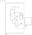
- the PGO stream is discharged from a side portion of the gasoline fractionator 10 of the naphtha cracking center process (S1) and may be a lower discharge stream which is discharged from a lower portion of a first stripper 20 after supplying a side discharge stream including the pyrolysis gas oil (PGO) to the first stripper 20, and the PFO stream is discharged from a lower portion of the gasoline fractionator 10 of the naphtha cracking center process (S1) and may be a lower discharge stream which is discharged from a lower portion of a second stripper 30 after supplying a lower discharge stream including the pyrolysis fuel oil (PFO) to the second stripper 30.
- S1 side portion of the gasoline fractionator 10 of the naphtha cracking center process
- PFO pyrolysis gas oil
- the first stripper 20 and the second stripper 30 may be a device in which a stripping process of separating and removing gas or vapor dissolved in a liquid is performed, and for example, may be performed by a method such as direct contact, heating, and pressing by, for example, steam, inert gas, or the like.
- the side discharge stream from the gasoline fractionator 10 is supplied to the first stripper 20, thereby refluxing an upper discharge stream from the first stripper 20 including a light fraction separated from the side discharge stream from the gasoline fractionator 10 to the gasoline fractionator 10.
- the lower discharge stream from the gasoline fractionator 10 is supplied to the second stripper 30, thereby refluxing an upper discharge stream from the second stripper 30 including a light fraction separated from the lower discharge stream from the gasoline fractionator 10 to the gasoline fractionator 10.
- the PGO stream may include 70 wt% or more or 70 wt% to 95 wt% of C10 to C12 hydrocarbons
- the PFO stream may include 70 wt% or more or 70 wt% to 98 wt% of C13+ hydrocarbons.
- the PGO stream including 70 wt% or more of C10 to C12 hydrocarbons may have a kinematic viscosity at 40°C of 1 to 200 cSt and a flash point of 10 to 50°C.
- the PFO stream including 70 wt% or more of C13+ hydrocarbons may have a kinematic viscosity at 40°C of 400 to 100,000 cSt and a flash point of 70 to 200°C.
- the PFO stream including more heavy hydrocarbons than the PGO stream may have a higher kinematic viscosity and a higher flash point than the pyrolysis gas oil under the same temperature conditions.
- the PGO stream may have a boiling point of 200 to 288°C or 210 to 270°C, and the PFO stream may have a boiling point of 289 to 550°C or 300 to 500°C.
- the boiling points of the PGO stream and the PFO stream may refer to the boiling points of the PGO stream and the PFO stream in a bulk form, each composed of a plurality of hydrocarbons.
- the kind of hydrocarbons included in the PGO stream and the kind of hydrocarbons included in the PFO stream may be different from each other, and some kinds may be the same.
- the kind of hydrocarbons included in the PGO stream and the PFO stream may be included as described above.
- the PFO stream and the PGO stream may be mixed to produce a mixed oil stream.
- a ratio of the flow rate of the PGO stream in the mixed oil stream relative to the flow rate of the mixed oil stream (hereinafter, referred to as "flow rate ratio of PGO stream”) may be 0.01 to 0.3, 0.01 to 0.2, or 0.05 to 0.2.
- the process of producing the mixed oil stream having the flow rate ratio of the PGO stream in the above range may be performed by adjusting the flow rates of the PGO stream and the PFO stream, using a first flow rate adjustment device V1, a second flow rate adjustment device V2, a third flow rate adjustment device V3, and a fourth flow rate adjustment device V4 shown in the pretreatment process (S2) of FIG. 1 . That is, the step (S10) may be performed by the pretreatment process (S2) of FIG. 1 .
- a gasifying agent and a raw material are supplied to the combustion chamber (not shown) positioned at the foremost end of the gasification process (S3) to produce synthesis gas by a combustion process at a temperature of 700°C or higher.
- the reaction of producing synthesis gas is performed under a high pressure of 20 to 80 atm, and the raw material in the combustion chamber should be moved at a high flow velocity of 2 to 40 m/s.
- the raw material should be pumped at a high flow velocity under a high pressure for the reaction of producing synthesis gas, and when the kinematic viscosity of the raw material supplied to the combustion chamber is higher than an appropriate range, a high-priced pump should be used due to reduced pumpability or costs are increased due to increased energy consumption, and pumping to desired conditions may be impossible.
- pumping since pumping is not performed well, the raw material may not be uniformly supplied to the combustion chamber.
- a differential pressure in the combustion chamber is raised or uniform atomization of the raw material is not performed well due to its small particle size, combustion performance may be deteriorated, productivity may be lowered, a large amount of gasifying agent is required, and a risk of explosion is increased due to excessive oxygen.
- an appropriate range of the kinematic viscosity may be somewhat different depending on the kind of synthesis gas, conditions of the combustion process performed in the combustion chamber, and the like, but generally, a lower kinematic viscosity of the raw material is better in terms of costs, productivity, and safety, at a temperature of the raw material at the time of supply to the combustion chamber in the gasification process (S3), and it is preferred that the kinematic viscosity is in a range of 300 cSt or less and within the range, a differential pressure rise in the combustion chamber is prevented within the range, and atomization is performed well to improve combustion performance.
- an appropriate range of the flash point may be varied depending on the kind of synthesis gas to be synthesized, conditions of the combustion process performed in the combustion chamber, and the like, but generally, it is preferred that the flash point of the raw material is in a range of being higher than the temperature of the raw material at the time of supply to the combustion chamber in the gasification process (S3) by 25°C or more, and within the range, a loss of the raw material, an explosion risk, and damage of refractories in the combustion chamber may be prevented.
- the flow rate ratio of the PGO stream and the PFO stream in the mixed oil stream may be adjusted. That is, by adjusting the flow rate ratio of the PGO stream and the PFO stream in the mixed oil stream, the kinematic viscosity and the flash point of the mixed oil stream may be controlled to an appropriate range at a temperature of the mixed oil stream at the time of supply to the combustion chamber.
- the temperature of the mixed oil stream at the time of supply to the combustion chamber may be lower than the flash point of the mixed oil stream at the time of supply to the combustion chamber by 25°C or more and may be a temperature at which the kinematic viscosity is 300 cSt or less.
- the kinematic viscosity of the mixed oil stream at the time of supply to the combustion chamber may be 300 cSt or less or 1 cSt to 300 cSt
- the flash point of the mixed oil stream may be higher than the temperature of the mixed oil stream at the time of supply to the combustion chamber by 25°C or more or 25°C to 150°C.
- the temperature of the mixed oil stream at the time of supply to the combustion chamber may be 20°C to 90°C or 30°C to 80°C.
- the kinematic viscosity of the mixed oil stream at the temperature at the time of supply to the combustion chamber within the range may be 300 cSt or less and may be lower than the flash point of the mixed oil stream by 25°C, and thus, may satisfy the process operating conditions for using the mixed oil stream as the raw material of the gasification process (S3).
- the flash point of the mixed oil stream may be higher than the temperature of the mixed oil stream at the time of supply by 25°C or more and the kinematic viscosity of the mixed oil stream may be in a range of 300 cSt or less at the temperature of the mixed oil stream at the time of supply.
- the PFO stream and the PGO stream are the heaviest residues in the NCC process and have been used as a simple fuel, and when they are used as a simple fuel as such, it is not necessary to adjust the compositions and the physical properties thereof.
- specific physical properties for example, both a kinematic viscosity and a flash point should be satisfied.
- the PGO stream satisfies the kinematic viscosity but has a too low flash point, and the PFO stream has a high flash point but has a too high kinematic viscosity, and thus, each stream may not satisfy both the kinematic viscosity and the flash point and it is difficult to use each of the streams as the raw material of the synthesis gas.
- a ratio of the flow rate of the PGO stream relative to the flow rate of the mixed oil stream is about 0.35 to 0.7, and in this case also, both the kinematic viscosity and the flash point may not be satisfied and it is difficult to use the stream as the raw material of the synthesis gas.
- the flash point of the mixed oil stream may be controlled to a range higher than the temperature of the mixed oil stream at the time of supply by 25°C or more and the kinematic viscosity may be controlled to a range of 300 cSt or less at the temperature of the mixed oil stream at the time of supply, and thus, the conditions for using the mixed oil stream as the raw material of the synthesis gas may be satisfied.
- the ratio of the flow rate of the PGO stream in the mixed oil stream relative to the flow rate of the mixed oil stream may be 0.01 or more. That is, when the PFO stream is supplied alone to the combustion chamber at the temperature satisfying the kinematic viscosity of 300 cSt, the conditions in which the flash point of the PFO stream is higher than the temperature at the time of supply by 25°C or more may not be satisfied. However, when the PFO stream is mixed with the PGO stream at the flow rate ratio range described above and supplied to the combustion chamber as the mixed oil stream, the conditions in which the flash point of the mixed oil stream is higher than the temperature at the time of supply satisfying the kinematic viscosity of 300 cSt by 25°C or more may be satisfied.
- a decrease in the kinematic viscosity is more increased than a decrease in the flash point, and thus, the flash point and the kinematic viscosity of the mixed oil stream at the time of supply of the mixed oil stream to the combustion chamber may be controlled to the ranges of the flash point and the kinematic viscosity described above.
- the conditions in which the flash point of the mixed oil stream is higher than the temperature at the time of supply satisfying the kinematic viscosity of 300 cSt by 25°C or more may be satisfied. That is, within the range of the flow rate ratio of the PGO stream described above, the flash point and the kinematic viscosity of the mixed oil stream at the time of supply to the combustion chamber may be controlled to the ranges of the flash point and the kinematic viscosity described above.
- a decrease in the flash point is more increased than a decrease in the kinematic viscosity, and thus, a temperature difference between the flash point of the mixed oil stream and the temperature at the time of supply satisfying the kinematic viscosity of 300 cSt is less than 25°C and the supply conditions to the combustion chamber may not be satisfied.
- the flash point and the kinematic viscosity of the mixed oil stream at the time of supply to the combustion chamber may be controlled, and thus, the mixed oil stream may have the physical properties appropriate for use as the raw material of the gasification process (S3).
- the PFO stream is directly supplied to the combustion chamber without the pretreatment process (S2) as shown in FIG. 2
- the PGO stream is directly supplied to the combustion chamber without the pretreatment process (S2) as shown in FIG. 3
- the PGO stream and the PFO stream are mixed but supplied to the combustion chamber at a flow rate ratio of the PGO stream out of the appropriate range of the present invention (0.01 to 0.3)
- a temperature satisfying both the kinematic viscosity and the flash point in the appropriate range described above may not exist.
- the mixed oil stream may pass through a heat exchanger 40 before being supplied to the combustion chamber for the gasification process (S3) to adjust the temperature to the temperature at the time of supply and then may be supplied to the combustion chamber.
- the mixed oil stream is produced by mixing the PGO stream at a high temperature discharged from the first stripper or the second stripper and the PFO stream, and may control the temperature to the temperature at the time of supply as the raw material of the synthesis gas and also reduce process energy, by reusing the sensible heat of the mixed oil stream which may be wasted as waste heat in the process using the heat exchanger 40.
- burning the mixed oil stream supplied to the combustion chamber in the gasification process (S3) at a temperature of 700°C or higher, 700 to 2000°C, or 800 to 1800°C (S30) may be further included.
- the mixed oil stream may be supplied to the combustion chamber together with the gasifying agent.
- the gasifying agent may include one or more selected from the group consisting of oxygen, air, and water vapor, and as a specific example, the gasifying agent may be oxygen or water vapor.
- the synthesis gas may be prepared.
- the synthesis gas prepared according to the preparation method of the present invention includes carbon monoxide and hydrogen and may further include one or more selected from the group consisting of carbon dioxide, ammonia, hydrogen sulfide, hydrogen cyanide, and carbonyl sulfide.
- devices such as a valve, a pump, a separator, and a mixer may be further installed.
- a side discharge stream discharged from a side portion of the gasoline fractionator 10 of a naphtha cracking center process was supplied to a first stripper 20, a PGO stream including a pyrolysis gas oil (PGO) was discharged from a lower portion of the first stripper 20, the lower discharge stream discharged from a lower portion of the gasoline fractionator 10 was supplied to a second stripper 30, and then a PFO stream including a pyrolysis fuel oil (PFO) was discharge from a lower portion of the second stripper 30.
- the flow rate ratio of the PGO stream and the PFO stream were adjusted and mixed by a pretreatment process (S2), thereby producing a mixed oil stream.
- the mixed oil stream was supplied to a combustion chamber in a gasification process (S3) with oxygen and vapor to prepare synthesis gas including hydrogen and carbon monoxide.
- the lower discharge stream discharged from a stage at 100% relative to the total number of stages of the gasoline fractionator 10 was supplied to the second stripper 30, the PFO stream including a pyrolysis fuel oil (PFO) was discharged from the lower portion of the second stripper 30, and it was confirmed that the content of C13+ in the PFO stream was 91 wt%.
- PFO pyrolysis fuel oil
- the lower discharge stream discharged from a stage at 100% relative to the total number of stages of the gasoline fractionator 10 was supplied to the second stripper 30, the PFO stream including a pyrolysis fuel oil (PFO) was discharged from the lower portion of the second stripper 30, and it was confirmed that the content of C13+ in the PFO stream was 96 wt%.
- PFO pyrolysis fuel oil
- the kinematic viscosity and the flash point were measured as follows, and were applied to all of the examples and the comparative examples.
- the process was performed in the same manner as in Example 1, except that the ratio of the flow rate of the PGO stream in the mixed oil stream relative to the flow rate of the mixed oil stream was set to be out of the appropriate range of the present invention (0.01 to 0.3).
- the synthesis gas was prepared according to the process flow diagram shown in FIG. 2 . More specifically, the lower discharge stream discharged from the lower portion of the gasoline fractionator 10 of the naphtha cracking center process (S1) was supplied to the second stripper 30, and then the PFO stream including a pyrolysis fuel oil (PFO) was discharged from the lower portion of the second stripper 30. Next, the PFO stream was supplied to the combustion chamber in the gasification process (S3) together with oxygen and vapor.
- S1 the lower discharge stream discharged from the lower portion of the gasoline fractionator 10 of the naphtha cracking center process
- PFO pyrolysis fuel oil
- the synthesis gas was prepared according to the process flow diagram shown in FIG. 3 . More specifically, the side discharge stream discharged from the side portion of the gasoline fractionator 10 of the naphtha cracking center process (S1) was supplied to the first stripper 20, and then the PGO stream including a pyrolysis gas oil (PGO) was discharged from the lower portion of the first stripper 20. Next, the PGO stream was supplied to the combustion chamber in the gasification process (S3) together with oxygen and vapor.
- S1 side discharge stream discharged from the side portion of the gasoline fractionator 10 of the naphtha cracking center process
- PGO pyrolysis gas oil
- the lower discharge stream discharged from a stage at 100% relative to the total number of stages of the gasoline fractionator 10 was supplied to the second stripper 30, the PFO stream including a pyrolysis fuel oil (PFO) was discharged from the lower portion of the second stripper 30, and it was confirmed that the content of C13+ in the PFO stream was 91 wt%.
- PFO pyrolysis fuel oil
- the lower discharge stream discharged from a stage at 100% relative to the total number of stages of the gasoline fractionator 10 was supplied to the second stripper 30, the PFO stream including a pyrolysis fuel oil (PFO) was discharged from the lower portion of the second stripper 30, and it was confirmed that the content of C13+ in the PFO stream was 96 wt%.
- PFO pyrolysis fuel oil
- the flash point and the kinematic viscosity at 40°C of each of the PGO stream and the PFO stream, the ratio of the flow rate of the PGO stream in the mixed oil stream relative to the flow rate of the mixed oil stream, the temperature of the mixed oil stream at the time of supply to the combustion chamber, and the flash point of the mixed oil stream were measured and are shown in the following Table 2. In addition, it was confirmed whether the process operating standards were satisfied according to the measurement results. At this time, the time when the mixed oil stream was supplied to the combustion chamber was set to temperature conditions to control the kinematic viscosity to 300 cSt.
Landscapes
- Chemical & Material Sciences (AREA)
- Organic Chemistry (AREA)
- Chemical Kinetics & Catalysis (AREA)
- Oil, Petroleum & Natural Gas (AREA)
- Engineering & Computer Science (AREA)
- General Chemical & Material Sciences (AREA)
- Health & Medical Sciences (AREA)
- General Health & Medical Sciences (AREA)
- Combustion & Propulsion (AREA)
- Inorganic Chemistry (AREA)
- Physics & Mathematics (AREA)
- Thermal Sciences (AREA)
- Production Of Liquid Hydrocarbon Mixture For Refining Petroleum (AREA)
- Hydrogen, Water And Hydrids (AREA)
- Carbon And Carbon Compounds (AREA)
Applications Claiming Priority (2)
| Application Number | Priority Date | Filing Date | Title |
|---|---|---|---|
| KR1020210013204A KR102778733B1 (ko) | 2021-01-29 | 2021-01-29 | 합성가스의 제조방법 |
| PCT/KR2021/018397 WO2022164006A1 (ko) | 2021-01-29 | 2021-12-06 | 합성가스의 제조방법 |
Publications (3)
| Publication Number | Publication Date |
|---|---|
| EP4074652A1 true EP4074652A1 (de) | 2022-10-19 |
| EP4074652A4 EP4074652A4 (de) | 2023-12-20 |
| EP4074652B1 EP4074652B1 (de) | 2026-04-22 |
Family
ID=82652991
Family Applications (1)
| Application Number | Title | Priority Date | Filing Date |
|---|---|---|---|
| EP21916629.5A Active EP4074652B1 (de) | 2021-01-29 | 2021-12-06 | Verfahren zur herstellung eines synthesegases |
Country Status (6)
| Country | Link |
|---|---|
| US (1) | US12534366B2 (de) |
| EP (1) | EP4074652B1 (de) |
| JP (1) | JP7413631B2 (de) |
| KR (1) | KR102778733B1 (de) |
| CN (1) | CN115135597B (de) |
| WO (1) | WO2022164006A1 (de) |
Family Cites Families (19)
| Publication number | Priority date | Publication date | Assignee | Title |
|---|---|---|---|---|
| US3862899A (en) * | 1972-11-07 | 1975-01-28 | Pullman Inc | Process for the production of synthesis gas and clean fuels |
| GB8803156D0 (en) * | 1988-02-11 | 1988-03-09 | Shell Int Research | Process for thermal cracking of residual hydrocarbon oils |
| US6149859A (en) | 1997-11-03 | 2000-11-21 | Texaco Inc. | Gasification plant for direct reduction reactors |
| CN1842584A (zh) * | 2003-08-29 | 2006-10-04 | 株式会社荏原制作所 | 回收方法和系统 |
| JP2008050303A (ja) | 2006-08-24 | 2008-03-06 | Mitsubishi Chemicals Corp | 蒸留系の制御方法、制御システム及び制御プログラム |
| KR100999304B1 (ko) | 2007-07-05 | 2010-12-08 | 주식회사 엘지화학 | 올레핀 제조용 탄화수소 열분해 방법 |
| ITMI20072228A1 (it) | 2007-11-23 | 2009-05-24 | Eni Spa | Procedimento per produrre gas di sintesi e idrogeno a partire da idrocarburi liquidi e gassosi |
| US7837857B2 (en) | 2007-12-24 | 2010-11-23 | Uop Llc | Hydrocracking process for fabricating jet fuel from diesel fuel |
| KR101101188B1 (ko) | 2009-02-25 | 2012-01-03 | 부국산업주식회사 | 연료유 인화점 조절 장치 |
| KR101123385B1 (ko) | 2009-11-06 | 2012-03-23 | 한국에너지기술연구원 | 오일샌드 역청을 이용한 2단 열분해 가스화 복합 장치 및 이를 이용한 합성가스와 연료유 동시 생산 방법 |
| KR101123384B1 (ko) | 2009-11-16 | 2012-03-23 | 한국에너지기술연구원 | 오일 분산성 나노첨가제를 이용한 중질유의 가스화 방법 |
| DE102012010542A1 (de) | 2011-12-20 | 2013-06-20 | CCP Technology GmbH | Verfahren und anlage zur erzeugung von synthesegas |
| CN103911180B (zh) | 2012-12-29 | 2016-06-29 | 新煤化工设计院(上海)有限公司 | 一种生产合成气的方法 |
| US11060039B2 (en) * | 2016-12-16 | 2021-07-13 | Exxonmobil Chemical Patents Inc. | Pyrolysis tar pretreatment |
| US10689587B2 (en) | 2017-04-26 | 2020-06-23 | Saudi Arabian Oil Company | Systems and processes for conversion of crude oil |
| US10815437B2 (en) * | 2017-12-29 | 2020-10-27 | Lummus Technology Llc | Conversion of heavy fuel oil to chemicals |
| US20190292467A1 (en) * | 2018-03-26 | 2019-09-26 | Convert Coal, Inc. | Oil products derived from diluted pyrolysis gas by continuous mild-temperature pyrolysis coal-tar separation process |
| KR102295333B1 (ko) | 2018-11-13 | 2021-08-27 | 한화토탈 주식회사 | 열분해 연료유를 이용한 벤젠, 톨루엔, 자일렌 제조방법 |
| WO2020242921A1 (en) * | 2019-05-24 | 2020-12-03 | Eastman Chemical Company | Recycle content cellulose ester |
-
2021
- 2021-01-29 KR KR1020210013204A patent/KR102778733B1/ko active Active
- 2021-12-06 EP EP21916629.5A patent/EP4074652B1/de active Active
- 2021-12-06 WO PCT/KR2021/018397 patent/WO2022164006A1/ko not_active Ceased
- 2021-12-06 CN CN202180014691.9A patent/CN115135597B/zh active Active
- 2021-12-06 JP JP2022542477A patent/JP7413631B2/ja active Active
- 2021-12-06 US US17/794,545 patent/US12534366B2/en active Active
Also Published As
| Publication number | Publication date |
|---|---|
| CN115135597A (zh) | 2022-09-30 |
| JP7413631B2 (ja) | 2024-01-16 |
| US20230264952A1 (en) | 2023-08-24 |
| CN115135597B (zh) | 2024-05-17 |
| JP2023516247A (ja) | 2023-04-19 |
| KR102778733B1 (ko) | 2025-03-07 |
| EP4074652B1 (de) | 2026-04-22 |
| KR20220109780A (ko) | 2022-08-05 |
| WO2022164006A1 (ko) | 2022-08-04 |
| EP4074652A4 (de) | 2023-12-20 |
| US12534366B2 (en) | 2026-01-27 |
Similar Documents
| Publication | Publication Date | Title |
|---|---|---|
| EP4079682B1 (de) | Verfahren zum produzieren eines synthesegases | |
| EP4074652B1 (de) | Verfahren zur herstellung eines synthesegases | |
| EP4074653B1 (de) | Verfahren zur herstellung eines synthesegases | |
| EP4155258A1 (de) | Verfahren zur herstellung von synthesegas | |
| US12441612B2 (en) | Method for preparing synthesis gas | |
| EP4174018A1 (de) | Verfahren zur herstellung von synthesegas und aromatischem kohlenwasserstoff | |
| EP4155256A1 (de) | Verfahren zur herstellung von synthesegas und aromatischen kohlenwasserstoffen |
Legal Events
| Date | Code | Title | Description |
|---|---|---|---|
| STAA | Information on the status of an ep patent application or granted ep patent |
Free format text: STATUS: UNKNOWN |
|
| STAA | Information on the status of an ep patent application or granted ep patent |
Free format text: STATUS: THE INTERNATIONAL PUBLICATION HAS BEEN MADE |
|
| PUAI | Public reference made under article 153(3) epc to a published international application that has entered the european phase |
Free format text: ORIGINAL CODE: 0009012 |
|
| STAA | Information on the status of an ep patent application or granted ep patent |
Free format text: STATUS: REQUEST FOR EXAMINATION WAS MADE |
|
| 17P | Request for examination filed |
Effective date: 20220711 |
|
| AK | Designated contracting states |
Kind code of ref document: A1 Designated state(s): AL AT BE BG CH CY CZ DE DK EE ES FI FR GB GR HR HU IE IS IT LI LT LU LV MC MK MT NL NO PL PT RO RS SE SI SK SM TR |
|
| A4 | Supplementary search report drawn up and despatched |
Effective date: 20231116 |
|
| RIC1 | Information provided on ipc code assigned before grant |
Ipc: C01B 3/32 20060101ALI20231110BHEP Ipc: C10G 9/02 20060101ALI20231110BHEP Ipc: C01B 3/36 20060101ALI20231110BHEP Ipc: C01B 3/34 20060101AFI20231110BHEP |
|
| DAV | Request for validation of the european patent (deleted) | ||
| DAX | Request for extension of the european patent (deleted) | ||
| GRAP | Despatch of communication of intention to grant a patent |
Free format text: ORIGINAL CODE: EPIDOSNIGR1 |
|
| STAA | Information on the status of an ep patent application or granted ep patent |
Free format text: STATUS: GRANT OF PATENT IS INTENDED |
|
| INTG | Intention to grant announced |
Effective date: 20260203 |
|
| GRAS | Grant fee paid |
Free format text: ORIGINAL CODE: EPIDOSNIGR3 |
|
| GRAA | (expected) grant |
Free format text: ORIGINAL CODE: 0009210 |
|
| STAA | Information on the status of an ep patent application or granted ep patent |
Free format text: STATUS: THE PATENT HAS BEEN GRANTED |
|
| AK | Designated contracting states |
Kind code of ref document: B1 Designated state(s): AL AT BE BG CH CY CZ DE DK EE ES FI FR GB GR HR HU IE IS IT LI LT LU LV MC MK MT NL NO PL PT RO RS SE SI SK SM TR |
|
| RAP3 | Party data changed (applicant data changed or rights of an application transferred) |
Owner name: LG CHEM, LTD. |
|
| REG | Reference to a national code |
Ref country code: CH Ref legal event code: F10 Free format text: ST27 STATUS EVENT CODE: U-0-0-F10-F00 (AS PROVIDED BY THE NATIONAL OFFICE) Effective date: 20260422 Ref country code: GB Ref legal event code: FG4D |