EP4074643B1 - Klemmvorrichtung und aufzugssystem - Google Patents
Klemmvorrichtung und aufzugssystem Download PDFInfo
- Publication number
- EP4074643B1 EP4074643B1 EP21209714.1A EP21209714A EP4074643B1 EP 4074643 B1 EP4074643 B1 EP 4074643B1 EP 21209714 A EP21209714 A EP 21209714A EP 4074643 B1 EP4074643 B1 EP 4074643B1
- Authority
- EP
- European Patent Office
- Prior art keywords
- stage
- force
- clamping device
- arm
- damping
- Prior art date
- Legal status (The legal status is an assumption and is not a legal conclusion. Google has not performed a legal analysis and makes no representation as to the accuracy of the status listed.)
- Active
Links
Images


Classifications
-
- B—PERFORMING OPERATIONS; TRANSPORTING
- B66—HOISTING; LIFTING; HAULING
- B66B—ELEVATORS; ESCALATORS OR MOVING WALKWAYS
- B66B11/00—Main component parts of lifts in, or associated with, buildings or other structures
- B66B11/02—Cages, i.e. cars
- B66B11/0226—Constructional features, e.g. walls assembly, decorative panels, comfort equipment, thermal or sound insulation
-
- B—PERFORMING OPERATIONS; TRANSPORTING
- B66—HOISTING; LIFTING; HAULING
- B66B—ELEVATORS; ESCALATORS OR MOVING WALKWAYS
- B66B7/00—Other common features of elevators
- B66B7/06—Arrangements of ropes or cables
-
- B—PERFORMING OPERATIONS; TRANSPORTING
- B66—HOISTING; LIFTING; HAULING
- B66B—ELEVATORS; ESCALATORS OR MOVING WALKWAYS
- B66B7/00—Other common features of elevators
-
- H—ELECTRICITY
- H01—ELECTRIC ELEMENTS
- H01B—CABLES; CONDUCTORS; INSULATORS; SELECTION OF MATERIALS FOR THEIR CONDUCTIVE, INSULATING OR DIELECTRIC PROPERTIES
- H01B7/00—Insulated conductors or cables characterised by their form
- H01B7/08—Flat or ribbon cables
Definitions
- the present application relates to the field of elevators. More specifically, the present application relates to a clamping device for preventing excessive swinging of a traveling cable of an elevator system.
- passenger transportation devices are very common in daily life.
- the most common passenger transportation devices are escalators and elevators that are usually used between floors of commercial buildings, and moving walkways that are usually used in large airports.
- An elevator system usually includes one or more elevator cars that can move along an elevator hoistway.
- a traveling cable will be additionally provided in the elevator hoistway.
- One end of such traveling cable may be connected to an elevator control system, and the other end may be operatively connected to the elevator car.
- the traveling cable In some application scenarios and hoistway structures or when affected by a variable-speed operation of the elevator car, the traveling cable often swings to a certain extent in the elevator hoistway.
- An example of the mentioned application scenarios may be a high-rise building, in which the traveling cable has a very large length and swings due to vibration conditions. Such an undesirable swinging process may interfere with brackets and/or other components in the elevator hoistway.
- this kind of swinging will also cause excessive wear of the traveling cable and affect its service life. Sudden excessive wear may even affect power supply of the elevator car and cause safety hazards.
- the SNAPTRACK product of Scidyne Corporation discloses a channel for mounting assemblies and custom circuit boards. Printed circuit boards snap-in from the front and are held securely by integral ribs that allow for removal.
- a clamping device is provided in accordance with claim 1.
- the clamping arm assembly is hinged to the base, and the clamping arm assembly is capable of rotating toward the limiting space under a driving force no less than the first damping force, and are capable of rotating away from the limiting space under a driving force no less than the second damping force.
- the clamping arm assembly includes: a first-stage force arm and a first-stage damping member, in which the first-stage damping member applies a damping force to the first-stage force arm when the first-stage force arm rotates either toward or away from the limiting space; and a second-stage force arm and a second-stage damping member, in which the second-stage force arm is associated with the first-stage force arm, and moves in association with the first-stage force arm when the first-stage force arm rotates away from the limiting space; and when the second-stage force arm moves in association, the second-stage damping member applies a damping force to the second-stage force arm; the damping force applied by the first-stage damping member is not greater than the first damping force, and a damping force applied by the first-stage damping member and the second-stage damping member in association is not greater than the second damping force.
- the first-stage force arm includes a first section and a second section; a first end of the first section and a first end of the second section are connected to each other and form an included angle, a first hinge point of the first-stage force arm and the base is arranged at a connection position of the first section and the second section, and the first-stage damping member is arranged at the first hinge point and abuts between a portion of the base that is close to the opening and the first section.
- a first end of the second-stage force arm abuts a side of the second section that is close to the first section and moves in association with the second section, and a second hinge point of the second-stage force arm and the base is arranged at a second end of the second-stage force arm; the second-stage damping member is arranged at the second hinge point and abuts between a portion of the base that is away from the opening and the second-stage force arm.
- the first-stage damping member is configured as a first torsion spring arranged around the first hinge point, and the first section further includes a first stop wall for abutting the first torsion spring; and/or the second-stage damping member is configured as a second torsion spring arranged around the second hinge point, and the second-stage force arm further includes a second stop wall for abutting the second torsion spring.
- two said clamping arm assemblies arranged oppositely are included; in which one of the clamping arm assemblies is hinged to the base at a first end of the opening, and the other one of the clamping arm assemblies is hinged to the base at a second end of the opening.
- the two clamping arm assemblies are aligned with each other.
- the rotatable end of the clamping arm assembly has a guiding arc surface, and the guiding arc surface is configured to follow the direction in which the clamped part enters and exits the limiting space via the opening.
- the base further includes a fixing portion that allows the base to be fixed to an installation position.
- an elevator system is provided in accordance with claim 11.
- the plurality of clamping devices are installed in the elevator hoistway at an interval of 6-8 meters.
- an upper portion of the traveling cable is fixed in the elevator hoistway.
- the traveling cable is configured to have a cross-section with a thickness smaller than a width; the traveling cable swings substantially in the thickness direction, and the clamping device is arranged to align with the traveling cable in the thickness direction.
- the clamping device of the present application by providing a clamping arm assembly that cooperates with the base, different damping forces that allow the clamped part (for example, the traveling cable, etc.) to enter and exit the limiting space of the base are provided, so that the clamped part can overcome a small first damping force and enter the limiting space, thereby restraining the clamped part in the limiting space and avoiding the collision and wear caused by excessive swinging; and the clamped part needs to overcome a larger second damping force to exit the limiting space. Therefore, the possibility of the clamped part being disengaged from the clamping device due to swinging is avoided, and only when an external force is required for deliberate traction, can the clamped part be disengaged from the clamping device.
- the clamped part for example, the traveling cable, etc.
- This arrangement has a low cost and can achieve reliable clamping of the clamped part.
- the elevator system to which this kind of clamping device is applied can thus reliably alleviate the undesired swinging of the traveling cable, increase its service life, and avoid the potential safety hazards caused thereby.
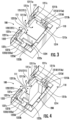
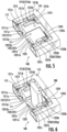
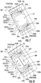
- the clamping device 100 generally includes a base 110 and two clamping arm assemblies 121, 122. In each of the figures, a clamping action of the clamping device 100 is shown by limiting a traveling cable of the elevator system, which will be described below in conjunction with the accompanying drawings.
- the base 110 is generally configured into the form of a frame made of sheet metal, thereby achieving a comprehensive consideration of both material and strength.
- the base 110 encloses a limiting space 111 with an opening 112, and the opening 112 communicates the limiting space 111 of the base 110 with an outer side of the base 110, i.e., a side that will typically face a clamped part in an installed position.
- clamping arm assemblies 121, 122 arranged opposite to each other are shown, in which one clamping arm assembly 121 is hinged to the base 110 at a first end of the opening 112, and the other clamping arm assembly 122 is hinged to the base 110 at a second end of the opening 112.
- the two clamping arm assemblies are aligned with each other in a stationary state, and form a gap smaller than the size of the clamped part with the opening 112. This arrangement makes the clamped part unable to enter or exit the limiting space 111 from the opening 112 in the stationary state.
- any one of the clamping arm assemblies 121, 122 is a component with damping that can initiate a movement after being driven, and has a first damping force that allows the clamped part to enter the limiting space 111 via the opening 112, and a second damping force that allows the clamped part to exit the limiting space 111 via the opening 112.
- the aforementioned second damping force is greater than the first damping force, which means that a greater driving force is required for forcing the clamped part to exit the limiting space 111 than forcing it to enter the limiting space 111.
- the clamping device 100 of this embodiment provides different damping forces that allow the clamped part (for example, a traveling cable 200, etc.) to enter and exit the limiting space 111 of the base 110.
- the clamped part for example, a traveling cable 200, etc.
- the clamped part When the clamped part is actively or passively subjected to an applied external force, it can overcome the smaller first damping force and enter the limiting space 111, so that it is restrained in the limiting space 111, and collision and wear caused by excessive swinging are avoided; and when the clamped part is actively or passively subjected to a greater external force, it needs to overcome a greater second damping force to exit the limiting space 111.
- this arrangement avoids the possibility of the clamped part being disengaged from the clamping device 100 due to swinging, and only when an external force is required for deliberate traction, can the clamped part be disengaged from the clamping device 100.
- This arrangement has a low cost and can achieve reliable clamping of the clamped part.
- clamping arm assemblies 121, 122 each include a first-stage force arm 1211, 1221 and a second-stage force arm 1213, 1223 associated with the first-stage force arm 1211, 1221 for providing support, and each include a first-stage damping member 1212, 1222 and a second-stage damping member 1214, 1224 for providing damping.
- the first-stage damping members 1212, 1222 each apply a damping force to the first-stage force arms 1211, 1221; and when the first-stage force arms 1211, 1221 rotate away from the limiting space 111, the first-stage damping members 1212, 1222 actuate the second-stage force arms 1213, 1223 to move in association therewith.
- the first-stage damping members 1212, 1222 apply a damping force to the first-stage force arms 1211, 1221
- the second-stage damping members 1214, 1224 apply a damping force to the second-stage force arms 1213, 1223.
- the damping force applied by the first-stage damping members 1212, 1222 should not be greater than the first damping force, and the damping force applied by the first-stage damping members 1212, 1222 and the second-stage damping members 1214, 1224 in association should not be greater than the second damping force.
- the damping force applied by the first-stage damping members 1212, 1222 and the second-stage damping members 1214, 1224 in association should not be greater than the second damping force.
- the corresponding first-stage force arms 1211, 1221 are configured into an "L"-shaped structure, and respectively include a first section 1211a, 1221a and a second section 1211b, 1221b.
- First ends 1213a, 1223a of the first sections 1211a, 1221a and first ends 1213a, 1223a of the second sections 1211b, 1221b are connected to each other and form an included angle; optionally, the included angle may for example be the right angle as shown in the figure.
- first hinge points 1211c, 1221c of the first-stage force arms 1211, 1221 and the base 110 are arranged at the connection positions of the first sections 1211a, 1221a and the second sections 1211b, 1221b, and at the same time, the first-stage damping members 1212, 1222 are arranged at these positions so that the first-stage damping members 1212, 1222 abut between a portion of the base 110 that is close to the opening 112 and the first sections 1211a, 1221a.
- first-stage damping members 1212, 1222 may be configured as first torsion springs 1212, 1222 arranged around first hinge posts 1211c, 1221c, and first stop walls 12111a, 12211a for abutting the first torsion springs 1212, 1222 are arranged on the first sections 1211a, 1221a.
- first-stage force arms 1211, 1221 receive a force toward the limiting space 111 from the clamped part, they will press the first torsion springs 1212, 1222 toward the limiting space 111 through the first stop walls 12111a, 12211a.
- the first torsion springs 1212, 1222 When the force is greater than the first damping force, the first torsion springs 1212, 1222 are forced to compress backward by a certain angle by the first stop walls. At this time, the first sections 1211a, 1221a of the first-stage force arms 1211, 1221 are rotated backward until a gap sufficient for the clamped part to pass through is exposed at the opening 112, thereby realizing the capture of the clamped part. When the clamped part enters the limiting space 111, the first-stage force arms 1211, 1221 are no longer subjected to the external force applied by the clamped part.
- the first torsion springs 1212, 1222 release the elastic energy, and push the first-stage force arms 1211, 1221 back to the initial positions through the first stop walls.
- the second-stage force arms 1213, 1223 are not actuated.
- the corresponding second-stage force arms 1213, 1223 are configured into a vertical strip structure, and first ends 1213a, 1223a thereof abut inner sides of the second sections 1211b, 1221b, and can move in association with the second sections 1211b, 1221b when the second sections 1211b, 1221b rotate toward the limiting space.
- Second hinge points 1213c, 1223c of the second-stage force arms 1213, 1223 and the base 110 are arranged at second ends 1213b, 1223b of the second-stage force arms 1213, 1223, thereby forming the fulcrum for the associated rotation.
- the second-stage damping members 1214, 1224 are arranged at the second hinge points 1213c, 1223c, and abut between a portion of the base 110 that is away from the opening 112 and the second-stage force arms 1213, 1223. More specifically, the second-stage damping members 1214, 1224 may be configured as second torsion springs 1214, 1224 arranged around second hinge posts 1213c, 1223c, and second stop walls 1213d, 1223d for abutting the second torsion springs 1214, 1224 are arranged on the second-stage force arms 1213, 1223.
- the first-stage force arms 1211, 1221 when the first-stage force arms 1211, 1221 receive a force away from the limiting space 111 from the clamped part located in the limiting space 111, the first-stage force arms 1211, 1221 will drive the first sections 1211a, 1221a of the first-stage force arms 1211, 1221 to rotate away from the limiting space 111.
- the second sections 1211b, 1221b of the first-stage force arms 1211, 1221 will rotate toward the limiting space 111, and the rotational movement path will be interfered by the second-stage force arms 1213, 1223, thereby making the second sections 1211b, 1221b still need to push the second-stage force arms 1213, 1223 to rotate.
- the external force from the clamped part needs to simultaneously overcome the damping forces of the first torsion springs 1212, 1222 and the second torsion springs. Specifically, when the force is greater than the second damping force, the first torsion springs 1212, 1222 and the second torsion springs 1214, 1224 are both compressed by a certain angle. At this time, the first sections 1211a, 1221a of the first-stage force arms 1211, 1221 will rotate outward until a gap sufficient for the clamped part to pass through is exposed at the opening 112, thereby realizing the release of the clamped part.
- the first-stage force arms 1211, 1221 and the second-stage force arms 1213, 1223 are no longer subjected to the external force applied by the clamped part.
- the first torsion springs 1212, 1222 and the second torsion springs 1214, 1224 both release the elastic energy, and push the first-stage force arms 1211, 1221 and the second-stage force arms 1213, 1223 back to their initial positions.
- the number of the clamping arm assemblies is not a necessary condition for restraining the clamped part.
- the clamping arm assembly can also rotate about the other end of the opening to form a path that can be passed through by the clamped part.
- the rotatable ends of the clamp arm assemblies 121, 122 may also be configured to have guiding arc surfaces 12112a, 12212a, and the guiding arc surfaces 12112a, 12212a are configured to follow the direction in which the clamped part enters and exits the limiting space 111 via the opening 112, so as to guide the clamped part into and out of the limiting space along the desired direction of movement.
- a fixing portion 113 may also be arranged on the base 110, and the fixing portion 113 allows the base 110 to be fixed to an installation position, so as to realize quick disassembly and assembly.
- an embodiment of an elevator system is also provided herein.
- the elevator system includes the clamping device 100 in any of the foregoing embodiments or combinations thereof, so it also has various effects brought about by it, which will not be repeated herein. The following will focus on the arrangement position of the clamping device 100 in the elevator system, its relationships with other components, and the additional technical effects brought about when it is applied to the elevator system.
- the elevator system further includes an elevator car configured to move up and down vertically along a plurality of car guide rails in the elevator hoistway.
- Guide assemblies (not shown) installed to the top and bottom of the elevator car are configured to engage the car guide rails so as to maintain proper alignment of the elevator car when the elevator car moves in the elevator hoistway.
- the elevator system further includes a counterweight device configured to move up and down vertically in the elevator hoistway.
- the counterweight device moves in a direction substantially opposite to the movement of the elevator car.
- the movement of the counterweight device is guided by counterweight device guide rails installed in the elevator hoistway.
- at least one load-bearing member (such as a belt or rope) is coupled to the elevator car and the counterweight device, and cooperates with a driving sheave installed to a driving machine. Therefore, the elevator car and the counterweight device move up and down along the elevator hoistway.
- the elevator system also includes a traveling cable 200 positioned in the elevator hoistway, and the traveling cable 200 can connect the elevator car to an elevator control system through a car operation panel in the elevator car.
- the traveling cable 200 may be utilized to provide electricity and/or communication to the elevator car.
- the traveling cable 200 is attached to the elevator car and/or enters the elevator car at the car floor of the elevator car, and can move along the elevator hoistway together with the elevator car.
- clamping devices 100 in any of the foregoing embodiments or combinations thereof, they can be respectively arranged in the elevator hoistway along the moving direction of the elevator car, and the clamping devices 100 can be aligned with the traveling cable 200 respectively.
- the traveling cable 200 in the downward movement process of the elevator car, when the swinging force of the traveling cable 200 is not less than the first damping force, the traveling cable 200 can swing to push away the clamping device 100 from the outside to the inside, and enter the limiting space 111 via the opening 112 so as to be restrained therein, thereby achieving reliable clamping of the traveling cable 200 at a lower cost, and avoiding collision and wear caused by excessive swinging.
- the traveling cable 200 can be pulled by the elevator car to push away the clamping device 100 from the inside to the outside, and exit the limiting space 111 via the opening 112.
- the elevator system can thus reliably alleviate the undesired swinging of the traveling cable 200, increase its service life, and avoid the potential safety hazards caused thereby.
- the traveling cable equipped therewith is also usually long.
- a single-point restraint strength and reliability of the clamping device are relatively insufficient.
- the swing strength of the traveling cable is positively related to its own total length and the running speed of the elevator car.
- the required maximum movement distance of the traveling cable 200 is only half of the traveling distance of the elevator car (or the depth of the elevator hoistway)
- the fixing of the upper half also reduces the length of the movable lower half of the traveling cable 200, thereby reducing its swinging strength.
- the traveling cable 200 used in an elevator system is generally configured to have a flat structure having a cross section with a thickness smaller than a width. It has been found through practice that this type of traveling cable 200 basically swings along its thickness direction with a relatively small size. Therefore, the clamping device 100 installed in the hoistway can be arranged in the thickness direction of the traveling cable 200 and aligned with the traveling cable 200, thereby having a better clamping and limiting effect on the traveling cable 200.
- clamping device provided by the present application and other parts of the elevator system can be designed, manufactured, and sold separately, or they can also be assembled together and then sold as a whole. Either the single pieces formed before the combination or the entirety formed after the combination will fall within the scope of protection of the present application.
Landscapes
- Engineering & Computer Science (AREA)
- Civil Engineering (AREA)
- Mechanical Engineering (AREA)
- Structural Engineering (AREA)
- Lift-Guide Devices, And Elevator Ropes And Cables (AREA)
Claims (14)
- Klemmvorrichtung (100), die Folgendes umfasst:eine Basis (110), die einen Begrenzungsraum (111) und eine Öffnung (112), die mit dem Begrenzungsraum (111) in Verbindung steht, aufweist; undeine Klemmarmbaugruppe (121, 122), die an der Öffnung (112) der Basis (110) angeordnet ist und in einem stationären Zustand einen Spalt mit der Öffnung (112) bildet, wobei der Spalt kleiner als eine Größe eines geklemmten Teils ist;wobei die Klemmarmbaugruppe (121, 122) eine erste Dämpfungskraft aufweist, die ermöglicht, dass das geklemmte Teil über die Öffnung (112) in den Begrenzungsraum (111) eintritt, und eine zweite Dämpfungskraft aufweist, die ermöglicht, dass das geklemmte Teil über die Öffnung (112) aus dem Begrenzungsraum (111) austritt; und die zweite Dämpfungskraft größer als die erste Dämpfungskraft ist;dadurch gekennzeichnet, dass:
die Klemmvorrichtung (100) dazu konfiguriert ist, ein Laufkabel (200) einer Aufzugssystems festzuklemmen oder freizugeben. - Klemmvorrichtung (100) nach Anspruch 1, wobei die Klemmarmbaugruppe (121, 122) an der Basis (110) angelenkt ist und die Klemmarmbaugruppe (121, 122) in der Lage ist, sich bei einer Antriebskraft, die nicht geringer als die erste Dämpfungskraft ist, in Richtung des Begrenzungsraums (111) zu drehen, und in der Lage ist, sich bei einer Antriebskraft, die nicht geringer als die zweite Dämpfungskraft ist, von dem Begrenzungsraum (111) weg zu drehen.
- Klemmvorrichtung (100) nach Anspruch 1 oder 2, wobei die Klemmarmbaugruppe (121, 122) Folgendes umfasst:einen Erststufen-Kraftarm (1211, 1221) und ein Erststufen-Dämpfungselement (1212, 1222), wobei das Erststufen-Dämpfungselement (1212, 1222) eine Dämpfungskraft auf den Erststufen-Kraftarm (1211, 1221) ausübt, wenn sich der Erststufen-Kraftarm (1211, 1221) entweder in Richtung des Begrenzungsraums (111) oder von diesem weg dreht; undeinen Zweitstufen-Kraftarm (1213, 1223) und ein Zweitstufen-Dämpfungselement (1214, 1224), wobei der Zweitstufen-Kraftarm (1213, 1223) dem Erststufen-Kraftarm (1211, 1221) zugeordnet ist und sich im Verbund mit dem Erststufen-Kraftarm (1211, 1221) bewegt, wenn sich der Erststufen-Kraftarm (1211, 1221) von dem Begrenzungsraum (111) weg dreht; und wobei, wenn sich der Zweitstufen-Kraftarm (1213, 1223) im Verbund bewegt, das Zweitstufen-Dämpfungselement (1214, 1224) eine Dämpfungskraft auf den Zweitstufen-Kraftarm (1213, 1223) ausübt;wobei die durch das Erststufen-Dämpfungselement (1212, 1222) ausgeübte Dämpfungskraft nicht größer als die erste Dämpfungskraft ist und eine durch das Erststufen-Dämpfungselement (1212, 1222) und das Zweitstufen-Dämpfungselement (1214, 1224) ausgeübte Dämpfungskraft im Verbund nicht größer als die zweite Dämpfungskraft ist.
- Klemmvorrichtung (100) nach Anspruch 3, wobei:der Erststufen-Kraftarm (1211, 1221) einen ersten Bereich (1211a, 1221a) und einen zweiten Bereich (1211b, 1221b) umfasst; ein erstes Ende (1213a, 1223a) des ersten Bereichs (1211a, 1221a) und ein erstes Ende (1213a, 1223a) des zweiten Bereichs (1211b, 1221b) miteinander verbunden sind und einen eingeschlossenen Winkel bilden, wobei ein erster Gelenkpunkt (1211c, 1221c) des Erststufen-Kraftarms (1211, 1221) und die Basis (110) an einer Verbindungsposition des ersten Bereichs (1211a, 1221a) und des zweiten Bereichs (1211b, 1221b) angeordnet sind; unddas Erststufen-Dämpfungselement (1212, 1222) an dem ersten Gelenkpunkt (1211c, 1221c) angeordnet ist und zwischen einem Abschnitt der Basis (110), der sich in der Nähe der Öffnung (112) befindet, und dem ersten Bereich (1211a, 1221a) anliegt.
- Klemmvorrichtung (100) nach Anspruch 4, wobei ein erstes Ende (1213a, 1223a) des Zweitstufen-Kraftarms (1213, 1223) auf einer Seite des zweiten Bereichs (1211b, 1221b), die sich in der Nähe des ersten Bereichs (1211a, 1221a) befindet, anliegt und sich im Verbund mit dem zweiten Bereich (1211b, 1221b) bewegt, und ein zweiter Gelenkpunkt (1213c, 1223c) des Zweitstufen-Kraftarms (1213, 1223) und die Basis (110) an einem zweiten Ende (1213b, 1223b) des Zweitstufen-Kraftarms (1213, 1223) angeordnet ist; und
das Zweitstufen-Dämpfungselement (1214, 1224) an dem zweiten Gelenkpunkt (1213c, 1223c) angeordnet ist und zwischen einem Abschnitt der Basis (110), der sich von der Öffnung (112) entfernt befindet, und dem Zweitstufen-Kraftarm (1213, 1223) anliegt. - Klemmvorrichtung (100) nach Anspruch 5, wobei:das Erststufen-Dämpfungselement (1212, 1222) als eine erste Torsionsfeder (1212, 1222) konfiguriert ist, die um den ersten Gelenkpunkt (1211c, 1221c) herum angeordnet ist, und der erste Bereich (1211a, 1221a) ferner eine erste Anschlagwand (12111a, 12211a) zum Anliegen an der ersten Torsionsfeder (1212, 1222) umfasst; und/oderdas Zweitstufen-Dämpfungselement (1214, 1224) als eine zweite Torsionsfeder (1214, 1224) konfiguriert ist, die um den zweiten Gelenkpunkt (1213c, 1223c) herum angeordnet ist, und der Zweitstufen-Kraftarm (1213, 1223) ferner eine zweite Anschlagwand (1213d, 1223d) zum Anliegen an der zweiten Torsionsfeder (1214, 1224) umfasst.
- Klemmvorrichtung (100) nach einem der Ansprüche 2 bis 6, umfassend zwei gegenüberliegend angeordnete Klemmarmbaugruppen (121, 122), wobei eine der Klemmarmbaugruppen (121, 122) an einem ersten Ende der Öffnung (112) an der Basis (110) angelenkt ist und die andere der Klemmarmbaugruppen (121, 122) an einem zweiten Ende der Öffnung (112) an der Basis (110) angelenkt ist.
- Klemmvorrichtung (100) nach Anspruch 7, wobei die zwei Klemmarmbaugruppen (121, 122) in einem stationären Zustand aneinander ausgerichtet sind.
- Klemmvorrichtung (100) nach einem der Ansprüche 2 bis 8, wobei das drehbare Ende der Klemmarmbaugruppe (121, 122) eine Führungsbogenfläche (12112a, 12212a) aufweist und die Führungsbogenfläche (12112a, 12212a) dazu konfiguriert ist, der Richtung zu folgen, in der das geklemmte Teil über die Öffnung (112) in den Begrenzungsraum (111) eintritt und aus diesem austritt.
- Klemmvorrichtung nach einem der vorhergehenden Ansprüche, wobei die Basis (110) ferner einen Befestigungsabschnitt (113) umfasst, der ermöglicht, dass die Basis (110) an einer Installationsposition befestigt ist.
- Aufzugssystem, das Folgendes umfasst:eine Aufzugskabine, die sich entlang eines Aufzugsschachts bewegen kann;ein Laufkabel (200), das mit der Aufzugskabine wirkverbunden ist und sich zusammen mit der Aufzugskabine entlang des Aufzugsschachts bewegen kann; undeine Vielzahl der Klemmvorrichtungen (100) nach einem der Ansprüche 1 bis 10, wobei jede in einer Bewegungsrichtung der Aufzugskabine in dem Aufzugsschacht angeordnet und jeweils an dem Laufkabel (200) ausgerichtet ist;wobei das Laufkabel (200) bei einem Abwärtsbewegungsvorgang der Aufzugskabine, wenn eine Schwingkraft des Laufkabels (200) nicht geringer als die erste Dämpfungskraft ist, schwingt, um über die Öffnung (112) der Klemmvorrichtung (100) in den Begrenzungsraum (111) einzutreten; undwobei das Laufkabel (200) bei einem Aufwärtsbewegungsvorgang der Aufzugskabine, wenn eine resultierende Kraft einer Traktionskraft der Aufzugskabine und eine Schwingkraft des Laufkabels (200) nicht geringer als die zweite Dämpfungskraft sind, durch die Aufzugskabine gezogen wird, um über die Öffnung (112) der Klemmvorrichtung (100) aus dem Begrenzungsraum (111) auszutreten.
- Aufzugssystem nach Anspruch 11, wobei die Vielzahl von Klemmvorrichtungen (100) in einem Abstand von 6-8 Metern in dem Aufzugsschacht installiert ist.
- Aufzugssystem nach Anspruch 11 oder 12, wobei ein oberer Abschnitt des Laufkabels (200) in dem Aufzugsschacht befestigt ist.
- Aufzugssystem nach Anspruch 11, 12 oder 13, wobei das Laufkabel (200) dazu konfiguriert ist, einen Querschnitt mit einer Dicke, die kleiner als eine Breite ist, aufzuweisen; wobei das Laufkabel (200) im Wesentlichen in Dickenrichtung schwingt und die Klemmvorrichtung (100) angeordnet ist, um sich in der Dickenrichtung an dem Laufkabel (200) auszurichten.
Applications Claiming Priority (1)
| Application Number | Priority Date | Filing Date | Title |
|---|---|---|---|
| CN202110394018.4A CN115196469A (zh) | 2021-04-13 | 2021-04-13 | 夹持装置及电梯系统 |
Publications (2)
| Publication Number | Publication Date |
|---|---|
| EP4074643A1 EP4074643A1 (de) | 2022-10-19 |
| EP4074643B1 true EP4074643B1 (de) | 2025-06-04 |
Family
ID=78725393
Family Applications (1)
| Application Number | Title | Priority Date | Filing Date |
|---|---|---|---|
| EP21209714.1A Active EP4074643B1 (de) | 2021-04-13 | 2021-11-22 | Klemmvorrichtung und aufzugssystem |
Country Status (3)
| Country | Link |
|---|---|
| US (1) | US11884515B2 (de) |
| EP (1) | EP4074643B1 (de) |
| CN (1) | CN115196469A (de) |
Family Cites Families (11)
| Publication number | Priority date | Publication date | Assignee | Title |
|---|---|---|---|---|
| US2017372A (en) * | 1934-05-21 | 1935-10-15 | American Steel & Wire Co | Guideway |
| US3686810A (en) * | 1970-11-05 | 1972-08-29 | Charles R Allen | Snap on drywall fastening system |
| US5644878A (en) * | 1995-01-11 | 1997-07-08 | Sony Corporation | Reusable finish trim for prefabricated clean room wall system |
| JPH1036038A (ja) | 1996-07-17 | 1998-02-10 | Mitsubishi Denki Bill Techno Service Kk | エレベータの調速機ロープ振れ止め装置 |
| US6234277B1 (en) | 1999-05-07 | 2001-05-22 | Draka Elevator Products, Inc. | Cable sway reduction device |
| JP3529312B2 (ja) * | 1999-12-24 | 2004-05-24 | ニチハ株式会社 | 建築板の留め付け構造 |
| US20100065381A1 (en) | 2006-12-20 | 2010-03-18 | Randall Keith Roberts | Sway mitigation in an elevator system |
| WO2013188211A1 (en) * | 2012-06-11 | 2013-12-19 | Dirtt Environmental Solutions Inc. | Modular building construction systems and methods |
| JP2014125305A (ja) | 2012-12-26 | 2014-07-07 | Hitachi Ltd | エレベータのテールコード制振装置 |
| US9328518B2 (en) * | 2013-01-22 | 2016-05-03 | Henry H. Bilge | Method and system for mounting wall panels to a wall |
| EP3760562B1 (de) * | 2019-07-05 | 2023-02-22 | Otis Elevator Company | Vorrichtung zur beschränkung des schaukelns in einem aufzugbewegungskabel |
-
2021
- 2021-04-13 CN CN202110394018.4A patent/CN115196469A/zh active Pending
- 2021-11-17 US US17/528,384 patent/US11884515B2/en active Active
- 2021-11-22 EP EP21209714.1A patent/EP4074643B1/de active Active
Also Published As
| Publication number | Publication date |
|---|---|
| EP4074643A1 (de) | 2022-10-19 |
| US20220324677A1 (en) | 2022-10-13 |
| CN115196469A (zh) | 2022-10-18 |
| US11884515B2 (en) | 2024-01-30 |
Similar Documents
| Publication | Publication Date | Title |
|---|---|---|
| US10294073B2 (en) | Elevator provided with a safety apparatus arrangement, and a safety apparatus | |
| EP1831093B1 (de) | Aufzugssystem mit mehreren kabinen in einem schacht | |
| EP3283425B1 (de) | Aufzugsystem | |
| EP2776355B1 (de) | Aufzugsystem | |
| KR20170037849A (ko) | 승강형 구조체용 제동 시스템 및 승강형 구조체 제동 제어 방법 | |
| CN107662865B (zh) | 随行电缆晃动的防止 | |
| JP2014525884A (ja) | 手動制動装置が付着された非常停止装置 | |
| US11059698B2 (en) | Elevator safety gear assembly | |
| KR100889280B1 (ko) | 엘리베이터의 로프 제동장치 | |
| US11884515B2 (en) | Clamping device and elevator system | |
| EP3154893B1 (de) | Aufzugsystem | |
| EP3274285B1 (de) | Aufhängungselementabschluss eines aufzugssystems | |
| KR102337522B1 (ko) | 엘리베이터 도어 상부 지지 조립체 | |
| EP4574731A1 (de) | Aufzugssicherheitsvorrichtung | |
| EP4678579A1 (de) | Aufzugssicherheitsbremsanordnung | |
| EP4717655A1 (de) | Aufzugsanlage mit einer führungsstruktur, die mindestens eine führungsschienenhalterung umfasst | |
| CN217996416U (zh) | 无机房电梯的绳头组件的安装结构以及无机房电梯 | |
| US12577083B2 (en) | Elevator safety device and method of activating an elevator safety device | |
| EP3929130B1 (de) | Sicherheitsverbindung mit einer rolle | |
| KR102368155B1 (ko) | 엘리베이터의 카 도어 클러치 장치 | |
| CN110467098B (zh) | 电梯轿厢门联接系统 | |
| EP3569548A1 (de) | Aufzugssicherheitsgetriebeanordnung | |
| HK1117126B (en) | Elevator system with multiple cars in a hoistway |
Legal Events
| Date | Code | Title | Description |
|---|---|---|---|
| PUAI | Public reference made under article 153(3) epc to a published international application that has entered the european phase |
Free format text: ORIGINAL CODE: 0009012 |
|
| STAA | Information on the status of an ep patent application or granted ep patent |
Free format text: STATUS: THE APPLICATION HAS BEEN PUBLISHED |
|
| AK | Designated contracting states |
Kind code of ref document: A1 Designated state(s): AL AT BE BG CH CY CZ DE DK EE ES FI FR GB GR HR HU IE IS IT LI LT LU LV MC MK MT NL NO PL PT RO RS SE SI SK SM TR |
|
| STAA | Information on the status of an ep patent application or granted ep patent |
Free format text: STATUS: REQUEST FOR EXAMINATION WAS MADE |
|
| 17P | Request for examination filed |
Effective date: 20230419 |
|
| RBV | Designated contracting states (corrected) |
Designated state(s): AL AT BE BG CH CY CZ DE DK EE ES FI FR GB GR HR HU IE IS IT LI LT LU LV MC MK MT NL NO PL PT RO RS SE SI SK SM TR |
|
| GRAP | Despatch of communication of intention to grant a patent |
Free format text: ORIGINAL CODE: EPIDOSNIGR1 |
|
| STAA | Information on the status of an ep patent application or granted ep patent |
Free format text: STATUS: GRANT OF PATENT IS INTENDED |
|
| INTG | Intention to grant announced |
Effective date: 20250213 |
|
| GRAS | Grant fee paid |
Free format text: ORIGINAL CODE: EPIDOSNIGR3 |
|
| GRAA | (expected) grant |
Free format text: ORIGINAL CODE: 0009210 |
|
| STAA | Information on the status of an ep patent application or granted ep patent |
Free format text: STATUS: THE PATENT HAS BEEN GRANTED |
|
| AK | Designated contracting states |
Kind code of ref document: B1 Designated state(s): AL AT BE BG CH CY CZ DE DK EE ES FI FR GB GR HR HU IE IS IT LI LT LU LV MC MK MT NL NO PL PT RO RS SE SI SK SM TR |
|
| REG | Reference to a national code |
Ref country code: GB Ref legal event code: FG4D |
|
| REG | Reference to a national code |
Ref country code: CH Ref legal event code: EP |
|
| REG | Reference to a national code |
Ref country code: DE Ref legal event code: R096 Ref document number: 602021031688 Country of ref document: DE |
|
| REG | Reference to a national code |
Ref country code: IE Ref legal event code: FG4D |
|
| REG | Reference to a national code |
Ref country code: NL Ref legal event code: MP Effective date: 20250604 |
|
| PG25 | Lapsed in a contracting state [announced via postgrant information from national office to epo] |
Ref country code: FI Free format text: LAPSE BECAUSE OF FAILURE TO SUBMIT A TRANSLATION OF THE DESCRIPTION OR TO PAY THE FEE WITHIN THE PRESCRIBED TIME-LIMIT Effective date: 20250604 Ref country code: ES Free format text: LAPSE BECAUSE OF FAILURE TO SUBMIT A TRANSLATION OF THE DESCRIPTION OR TO PAY THE FEE WITHIN THE PRESCRIBED TIME-LIMIT Effective date: 20250604 |
|
| REG | Reference to a national code |
Ref country code: LT Ref legal event code: MG9D |
|
| PG25 | Lapsed in a contracting state [announced via postgrant information from national office to epo] |
Ref country code: NO Free format text: LAPSE BECAUSE OF FAILURE TO SUBMIT A TRANSLATION OF THE DESCRIPTION OR TO PAY THE FEE WITHIN THE PRESCRIBED TIME-LIMIT Effective date: 20250904 Ref country code: GR Free format text: LAPSE BECAUSE OF FAILURE TO SUBMIT A TRANSLATION OF THE DESCRIPTION OR TO PAY THE FEE WITHIN THE PRESCRIBED TIME-LIMIT Effective date: 20250905 |
|
| PG25 | Lapsed in a contracting state [announced via postgrant information from national office to epo] |
Ref country code: PL Free format text: LAPSE BECAUSE OF FAILURE TO SUBMIT A TRANSLATION OF THE DESCRIPTION OR TO PAY THE FEE WITHIN THE PRESCRIBED TIME-LIMIT Effective date: 20250604 |
|
| PG25 | Lapsed in a contracting state [announced via postgrant information from national office to epo] |
Ref country code: BG Free format text: LAPSE BECAUSE OF FAILURE TO SUBMIT A TRANSLATION OF THE DESCRIPTION OR TO PAY THE FEE WITHIN THE PRESCRIBED TIME-LIMIT Effective date: 20250604 |
|
| PG25 | Lapsed in a contracting state [announced via postgrant information from national office to epo] |
Ref country code: HR Free format text: LAPSE BECAUSE OF FAILURE TO SUBMIT A TRANSLATION OF THE DESCRIPTION OR TO PAY THE FEE WITHIN THE PRESCRIBED TIME-LIMIT Effective date: 20250604 |
|
| PG25 | Lapsed in a contracting state [announced via postgrant information from national office to epo] |
Ref country code: RS Free format text: LAPSE BECAUSE OF FAILURE TO SUBMIT A TRANSLATION OF THE DESCRIPTION OR TO PAY THE FEE WITHIN THE PRESCRIBED TIME-LIMIT Effective date: 20250904 |
|
| PG25 | Lapsed in a contracting state [announced via postgrant information from national office to epo] |
Ref country code: LV Free format text: LAPSE BECAUSE OF FAILURE TO SUBMIT A TRANSLATION OF THE DESCRIPTION OR TO PAY THE FEE WITHIN THE PRESCRIBED TIME-LIMIT Effective date: 20250604 |
|
| PG25 | Lapsed in a contracting state [announced via postgrant information from national office to epo] |
Ref country code: NL Free format text: LAPSE BECAUSE OF FAILURE TO SUBMIT A TRANSLATION OF THE DESCRIPTION OR TO PAY THE FEE WITHIN THE PRESCRIBED TIME-LIMIT Effective date: 20250604 |
|
| PG25 | Lapsed in a contracting state [announced via postgrant information from national office to epo] |
Ref country code: PT Free format text: LAPSE BECAUSE OF FAILURE TO SUBMIT A TRANSLATION OF THE DESCRIPTION OR TO PAY THE FEE WITHIN THE PRESCRIBED TIME-LIMIT Effective date: 20251006 |
|
| REG | Reference to a national code |
Ref country code: AT Ref legal event code: MK05 Ref document number: 1800209 Country of ref document: AT Kind code of ref document: T Effective date: 20250604 |
|
| PG25 | Lapsed in a contracting state [announced via postgrant information from national office to epo] |
Ref country code: IS Free format text: LAPSE BECAUSE OF FAILURE TO SUBMIT A TRANSLATION OF THE DESCRIPTION OR TO PAY THE FEE WITHIN THE PRESCRIBED TIME-LIMIT Effective date: 20251004 |
|
| PGFP | Annual fee paid to national office [announced via postgrant information from national office to epo] |
Ref country code: DE Payment date: 20251022 Year of fee payment: 5 |
|
| PG25 | Lapsed in a contracting state [announced via postgrant information from national office to epo] |
Ref country code: SM Free format text: LAPSE BECAUSE OF FAILURE TO SUBMIT A TRANSLATION OF THE DESCRIPTION OR TO PAY THE FEE WITHIN THE PRESCRIBED TIME-LIMIT Effective date: 20250604 Ref country code: AT Free format text: LAPSE BECAUSE OF FAILURE TO SUBMIT A TRANSLATION OF THE DESCRIPTION OR TO PAY THE FEE WITHIN THE PRESCRIBED TIME-LIMIT Effective date: 20250604 |
|
| PGFP | Annual fee paid to national office [announced via postgrant information from national office to epo] |
Ref country code: FR Payment date: 20251022 Year of fee payment: 5 |
|
| PG25 | Lapsed in a contracting state [announced via postgrant information from national office to epo] |
Ref country code: CZ Free format text: LAPSE BECAUSE OF FAILURE TO SUBMIT A TRANSLATION OF THE DESCRIPTION OR TO PAY THE FEE WITHIN THE PRESCRIBED TIME-LIMIT Effective date: 20250604 |
|
| PG25 | Lapsed in a contracting state [announced via postgrant information from national office to epo] |
Ref country code: EE Free format text: LAPSE BECAUSE OF FAILURE TO SUBMIT A TRANSLATION OF THE DESCRIPTION OR TO PAY THE FEE WITHIN THE PRESCRIBED TIME-LIMIT Effective date: 20250604 |
|
| PG25 | Lapsed in a contracting state [announced via postgrant information from national office to epo] |
Ref country code: SK Free format text: LAPSE BECAUSE OF FAILURE TO SUBMIT A TRANSLATION OF THE DESCRIPTION OR TO PAY THE FEE WITHIN THE PRESCRIBED TIME-LIMIT Effective date: 20250604 |
|
| PG25 | Lapsed in a contracting state [announced via postgrant information from national office to epo] |
Ref country code: IT Free format text: LAPSE BECAUSE OF FAILURE TO SUBMIT A TRANSLATION OF THE DESCRIPTION OR TO PAY THE FEE WITHIN THE PRESCRIBED TIME-LIMIT Effective date: 20250604 |
|
| PG25 | Lapsed in a contracting state [announced via postgrant information from national office to epo] |
Ref country code: RO Free format text: LAPSE BECAUSE OF FAILURE TO SUBMIT A TRANSLATION OF THE DESCRIPTION OR TO PAY THE FEE WITHIN THE PRESCRIBED TIME-LIMIT Effective date: 20250604 |
|
| REG | Reference to a national code |
Ref country code: DE Ref legal event code: R097 Ref document number: 602021031688 Country of ref document: DE |
|
| PLBE | No opposition filed within time limit |
Free format text: ORIGINAL CODE: 0009261 |
|
| STAA | Information on the status of an ep patent application or granted ep patent |
Free format text: STATUS: NO OPPOSITION FILED WITHIN TIME LIMIT |
|
| PG25 | Lapsed in a contracting state [announced via postgrant information from national office to epo] |
Ref country code: DK Free format text: LAPSE BECAUSE OF FAILURE TO SUBMIT A TRANSLATION OF THE DESCRIPTION OR TO PAY THE FEE WITHIN THE PRESCRIBED TIME-LIMIT Effective date: 20250604 |
|
| REG | Reference to a national code |
Ref country code: CH Ref legal event code: L10 Free format text: ST27 STATUS EVENT CODE: U-0-0-L10-L00 (AS PROVIDED BY THE NATIONAL OFFICE) Effective date: 20260416 |
|
| 26N | No opposition filed |
Effective date: 20260305 |