EP4072256B1 - Mehrtemperaturkontrollschrank und planungsverfahren für einen mehrtemperatursteuerungsschrank - Google Patents
Mehrtemperaturkontrollschrank und planungsverfahren für einen mehrtemperatursteuerungsschrank Download PDFInfo
- Publication number
- EP4072256B1 EP4072256B1 EP22166765.2A EP22166765A EP4072256B1 EP 4072256 B1 EP4072256 B1 EP 4072256B1 EP 22166765 A EP22166765 A EP 22166765A EP 4072256 B1 EP4072256 B1 EP 4072256B1
- Authority
- EP
- European Patent Office
- Prior art keywords
- air
- cabinet
- humidity
- temperature
- air conditioner
- Prior art date
- Legal status (The legal status is an assumption and is not a legal conclusion. Google has not performed a legal analysis and makes no representation as to the accuracy of the status listed.)
- Active
Links
Images


Classifications
-
- H—ELECTRICITY
- H05—ELECTRIC TECHNIQUES NOT OTHERWISE PROVIDED FOR
- H05K—PRINTED CIRCUITS; CASINGS OR CONSTRUCTIONAL DETAILS OF ELECTRIC APPARATUS; MANUFACTURE OF ASSEMBLAGES OF ELECTRICAL COMPONENTS
- H05K5/00—Casings, cabinets or drawers for electric apparatus
- H05K5/02—Details
- H05K5/0213—Venting apertures; Constructional details thereof
-
- H—ELECTRICITY
- H05—ELECTRIC TECHNIQUES NOT OTHERWISE PROVIDED FOR
- H05K—PRINTED CIRCUITS; CASINGS OR CONSTRUCTIONAL DETAILS OF ELECTRIC APPARATUS; MANUFACTURE OF ASSEMBLAGES OF ELECTRICAL COMPONENTS
- H05K7/00—Constructional details common to different types of electric apparatus
- H05K7/20—Modifications to facilitate cooling, ventilating, or heating
- H05K7/20536—Modifications to facilitate cooling, ventilating, or heating for racks or cabinets of standardised dimensions, e.g. electronic racks for aircraft or telecommunication equipment
- H05K7/207—Thermal management, e.g. cabinet temperature control
-
- H—ELECTRICITY
- H05—ELECTRIC TECHNIQUES NOT OTHERWISE PROVIDED FOR
- H05K—PRINTED CIRCUITS; CASINGS OR CONSTRUCTIONAL DETAILS OF ELECTRIC APPARATUS; MANUFACTURE OF ASSEMBLAGES OF ELECTRICAL COMPONENTS
- H05K7/00—Constructional details common to different types of electric apparatus
- H05K7/20—Modifications to facilitate cooling, ventilating, or heating
- H05K7/20009—Modifications to facilitate cooling, ventilating, or heating using a gaseous coolant in electronic enclosures
- H05K7/20136—Forced ventilation, e.g. by fans
- H05K7/20145—Means for directing air flow, e.g. ducts, deflectors, plenum or guides
-
- H—ELECTRICITY
- H05—ELECTRIC TECHNIQUES NOT OTHERWISE PROVIDED FOR
- H05K—PRINTED CIRCUITS; CASINGS OR CONSTRUCTIONAL DETAILS OF ELECTRIC APPARATUS; MANUFACTURE OF ASSEMBLAGES OF ELECTRICAL COMPONENTS
- H05K5/00—Casings, cabinets or drawers for electric apparatus
- H05K5/02—Details
-
- H—ELECTRICITY
- H05—ELECTRIC TECHNIQUES NOT OTHERWISE PROVIDED FOR
- H05K—PRINTED CIRCUITS; CASINGS OR CONSTRUCTIONAL DETAILS OF ELECTRIC APPARATUS; MANUFACTURE OF ASSEMBLAGES OF ELECTRICAL COMPONENTS
- H05K5/00—Casings, cabinets or drawers for electric apparatus
- H05K5/02—Details
- H05K5/0217—Mechanical details of casings
- H05K5/0226—Hinges
-
- H—ELECTRICITY
- H05—ELECTRIC TECHNIQUES NOT OTHERWISE PROVIDED FOR
- H05K—PRINTED CIRCUITS; CASINGS OR CONSTRUCTIONAL DETAILS OF ELECTRIC APPARATUS; MANUFACTURE OF ASSEMBLAGES OF ELECTRICAL COMPONENTS
- H05K7/00—Constructional details common to different types of electric apparatus
- H05K7/20—Modifications to facilitate cooling, ventilating, or heating
- H05K7/20009—Modifications to facilitate cooling, ventilating, or heating using a gaseous coolant in electronic enclosures
- H05K7/20209—Thermal management, e.g. fan control
Definitions
- the present invention relates to the field of cabinet technologies, and in particular, to a multi-temperature control cabinet and a scheduling method for a multi-temperature control cabinet.
- a cabinet is a freestanding or self-supporting housing that accommodates electrical or electronic equipment.
- a door, a removable or non-removable side panel, and a backplane are usually configured for the cabinet.
- the cabinet is an indispensable component of electrical equipment and is a carrier of electrical control equipment.
- the cabinet is usually made of a cold-rolled steel plate or an alloy, and can provide protection functions such as waterproof, dustproof, and electromagnetic interference prevention for a stored device.
- a temperature adjustment system is disposed in the cabinet to ensure that the device in the cabinet can run in a stable environment.
- an air conditioner and direct ventilation are disposed in a cabinet to adjust temperature in the cabinet. Both the air conditioner and the direct ventilation are connected to a temperature control component.
- the temperature control component is configured to: monitor the temperature in the cabinet, and control turning-on and turning-off of the air conditioner and the direct ventilation by using the temperature in the cabinet. Specifically, when the temperature in the cabinet is relatively high, the air conditioner starts to run, and the direct ventilation does not run; or when the temperature in the cabinet is relatively low, the air conditioner is turned off, and the direct ventilation starts to work, to adjust the temperature in the cabinet.
- the controlling the turning-on and the turning-off of the air conditioner and the direct ventilation by using the temperature control component causes fluctuation of humidity in the cabinet, and in a serious case, causes a high-humidity alarm and condensation of a device in the cabinet.
- EP 1367331 A1 describes a compact air-cooling device for a closed technical cabinet.
- the compact air-cooling device comprises a housing, an evaporator, a condenser, a compressor, a primary fan and secondary fan.
- Partition elements define a primary air circuit, which allows mechanical cooling in a closed loop with air from the inside of the closed technical cabinet, and a secondary air circuit, which allows to cool the condenser with air from the outside of the closed technical cabinet.
- These partition elements include movable elements that can be brought into an auxiliary position, so that the secondary air circuit is in communication with the primary air circuit upstream of the evaporator, and the inside air intake chamber is sealed off from the primary air circuit and is in direct communication with the outside environment of the closed technical cabinet.
- EP 3758 175 A1 describes an electrical housing comprising a frame and a door.
- the door is articulated on the frame and is fitted with an air conditioning unit housed in an opening formed through the door.
- Supports are fastened to the inner surface of the door on each side of the opening, and each support is equipped with at least one housing for receiving and blocking a portion of a pin carried by the air conditioning unit by gravity.
- At least one mechanical device mounted on the inner surface of the door enables each pin to be locked in its housing in a blocking configuration.
- the cabinet comprises a cabinet body, a front cabinet door and a back cabinet door.
- the cabinet body is internally provided with an arrangement frame; the front cabinet door is provided with a first heat exchange temperature control unit; the air outlet of the first heat exchange temperature control unit is disposed at the lower end of the inner side surface of the front cabinet door; the back cabinet door is provided with a second heat exchange temperature control unit; the air outlet of the second heat exchange temperature control unit is disposed at the lower end of the inner side surface of the back cabinet door;
- the cabinet body is internally provided with a temperature sensor; the temperature sensor is connected with the first heat exchange temperature control unit and the second heat exchange temperature control unit; and the top portion of the cabinet body is provided with a drawing fan, such that each heat exchange temperature control unit is automatically controlled by using the temperature sensor to sense the temperature of the cabinet body and is enabled to generate cold air to cool the inside of the cabinet body, and at the same time, the heat quantity inside the cabinet body is extracted by use of the drawing fan, thus the
- Embodiments of this application provide a multi-temperature control cabinet and a scheduling method for a multi-temperature control cabinet, to resolve a technical problem that condensation is likely to be caused due to fluctuation of humidity in the cabinet.
- a first aspect of embodiments of this application provides a multi-temperature control cabinet, including a cabinet body, a cabinet door, and a refrigerating system.
- the refrigerating system includes an air conditioner, a direct ventilation unit, and an environment monitoring apparatus. Both the air conditioner and the direct ventilation unit are disposed on the cabinet door, and the air conditioner and the direct ventilation unit are disposed in parallel in a height direction of the cabinet door.
- An air guide assembly is disposed between the direct ventilation unit and an air exhaust vent of the air conditioner.
- the environment monitoring apparatus is connected to both the air conditioner and the direct ventilation unit, and the environment monitoring apparatus is configured to: monitor temperature and humidity in the cabinet body, and control turning-on and turning-off of the air conditioner and the direct ventilation unit based on the temperature and the humidity in the cabinet body.
- the air conditioner, the direct ventilation unit, and the environment monitoring apparatus are disposed, and the turning-on and the turning-off of the air conditioner and the direct ventilation unit are jointly controlled by using the temperature and the humidity that are monitored by the environment monitoring apparatus. Therefore, ranges of the humidity and the temperature inside the cabinet can be accurately controlled, so that condensation caused when the cabinet door is opened can be alleviated and frequent high-humidity or low-humidity alarms in the cabinet can be reduced, thereby reducing site maintenance frequency and reducing maintenance costs.
- the direct ventilation unit includes an air intake unit and an air exhaust unit.
- the air guide assembly is disposed between the air intake unit and the air exhaust vent of the air conditioner.
- the air intake unit is located below the air conditioner.
- the air exhaust unit is disposed above the air conditioner.
- the air guide assembly is disposed between an air exhaust vent of the air conditioner and the air intake unit on the first cabinet door.
- An air intake vent, an air mixing channel, and a mixed-air exhaust vent are disposed on the air guide assembly.
- the air mixing channel is connected to both the air intake vent and the mixed-air exhaust vent.
- the air intake vent is connected to both the air exhaust vent of the air conditioner and the air intake unit.
- the air guide assembly is of a barrel-like structure.
- the air intake vent includes a first air intake vent and a second air intake vent.
- the first air intake vent is connected to the air exhaust vent of the air conditioner.
- the second air intake vent is connected to the air intake unit.
- a material of the air guide assembly is sheet metal or plastic.
- the environment monitoring apparatus includes a temperature monitoring component and a humidity monitoring component.
- the temperature monitoring component is configured to monitor the temperature in the cabinet body.
- the humidity monitoring component is configured to monitor the humidity in the cabinet body.
- a second aspect of this application provides a scheduling method for a multi-temperature control cabinet, used to adjust temperature and humidity in the foregoing multi-temperature control cabinet.
- the method includes:
- the controlling turning-on and turning-off of an air conditioner and a direct ventilation unit based on monitored temperature and humidity values includes:
- the controlling turning-on and turning-off of an air conditioner and a direct ventilation unit based on monitored temperature and humidity values includes:
- the method further includes:
- the method further includes:
- the method further includes:
- the method further includes:
- the method further includes:
- An embodiment of this application provides a multi-temperature control cabinet.
- the multi-temperature control cabinet is used as an outdoor power cabinet, an outdoor device cabinet, an indoor device cabinet, an indoor power cabinet, or the like.
- An embodiment of this application provides a multi-temperature control cabinet.
- the multi-temperature control cabinet can adjust temperature and humidity in the cabinet, so that it can be ensured that a device in the cabinet can normally run in a proper temperature range.
- the multi-temperature control cabinet can further adjust the humidity in the cabinet, to resolve fluctuation of the humidity in the cabinet that is caused due to temperature adjustment.
- an air conditioner is usually installed in a cabinet, and temperature is used as a parameter for controlling turning-on and turning off of the air conditioner.
- the cabinet is relatively sealed space.
- the air conditioner is used to adjust temperature, humidity in the cabinet changes. Specifically, after the air conditioner is turned on for a period of time, both the temperature and the humidity in the cabinet decrease. When the temperature decreases to a preset temperature, the air conditioner is turned off. In this adjustment manner, the air conditioner needs to be frequently turned on and turned off. This improves energy consumption; and also causes fluctuation of the humidity in the cabinet, and in a serious case, causes a high-humidity alarm and condensation of a device in the cabinet.
- embodiments provide a multi-temperature control cabinet, to resolve a technical problem that condensation is likely to be caused due to fluctuation of humidity in the cabinet.
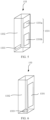
- this embodiment provides a multi-temperature control cabinet 10.
- the multi-temperature control cabinet 10 includes a cabinet body 11, one cabinet door 12, and a refrigerating system 13.
- the refrigerating system 13 includes one air conditioner 131, one direct ventilation unit 132, an air guide assembly 133 (shown in FIG. 2 ), and an environment monitoring apparatus (not shown in the figure).
- both the air conditioner 131 and the direct ventilation unit 132 are disposed on the cabinet door 12, and the air conditioner 131 and the direct ventilation unit 132 are disposed in parallel in a height direction of the cabinet door 12.
- the environment monitoring apparatus is connected to both the air conditioner 131 and the direct ventilation unit 132, and the environment monitoring apparatus is configured to: monitor temperature and humidity in the cabinet body 11, and control turning-on and turning-off of the air conditioner 131 and the direct ventilation unit 132 based on the temperature and the humidity in the cabinet body 11.
- the environment monitoring apparatus is disposed to monitor the temperature and the humidity in the cabinet 10, and control the turning-on and the turning-off of the direct ventilation unit 132 and the air conditioner 131 based on the temperature and the humidity in the cabinet 10, to ensure that both the temperature and the humidity in the cabinet 10 are in a relatively stable state, so that fluctuation of the humidity in the cabinet 10 is effectively avoided and condensation in the cabinet 10 can be avoided, thereby ensuring normal running of a device in the cabinet 10.
- FIG. 1 there may be one cabinet door 12.
- one or more air conditioners 131 and one or more direct ventilation units 132 may be disposed on the cabinet door 12.
- an example in which one air conditioner 131 and one direct ventilation unit 132 are disposed on the cabinet door 12 is specifically used for description.
- the cabinet body 11 of the multi-temperature control cabinet 10 is of a cuboid cabinet-like structure.
- the cabinet door 12 is rotatably disposed on one side of the cabinet body 11, the cabinet door 12 can be opened and closed relative to the cabinet body 11, and when the cabinet door 12 is in a closed state, the cabinet body 11 and the cabinet door 12 form closed space.
- An installation component for installing electrical equipment and the electrical equipment are disposed inside the cabinet body 11, and a specific position of the installation component is not specifically limited herein.
- the environment monitoring apparatus may be installed on the cabinet body 11, may be installed on the cabinet door 12, or may be installed on the installation component in the cabinet body 11, provided that the environment monitoring apparatus can monitor the temperature and the humidity in the cabinet 10 and can control the turning-on and the turning-off of the air conditioner 131 and the direct ventilation unit 132.
- the air conditioner 131 in this embodiment may be an integrated air conditioner.
- An air exhaust vent 1311 and an air return vent 1312 of the air conditioner 131 are disposed on the integrated air conditioner, and a side on which the air exhaust vent 1311 and the air return vent 1312 of the air conditioner 131 are disposed faces the inside of the cabinet body 11, to adjust the temperature inside the cabinet 10.
- a model of the integrated air conditioner is not limited herein, provided that the integrated air conditioner can conveniently adjust the temperature in the cabinet 10.
- the direct ventilation unit 132 includes an air intake unit 1321 and an air exhaust unit 1322.
- the air intake unit 1321 can suck natural air outside the cabinet 10 into the cabinet 10, and then the air is exhausted out of the cabinet 10 through the air exhaust unit 1322.
- the air intake unit 1321 is disposed below the air conditioner 131, and the air exhaust unit 1322 is disposed above the air conditioner 131. It should be noted that, because air rises due to thermal expansion, hot air is located above cold air in the cabinet 10.
- the disposing the air exhaust unit 1322 of the direct ventilation unit 132 above the air conditioner 131 helps exhaust the hot air in the cabinet 10 to the outside of the cabinet 10 through the air exhaust unit 1322, to implement exchange between air in the cabinet 10 and external air, thereby reducing the temperature in the cabinet 10 and balancing the humidity in the cabinet 10.
- the air guide assembly 133 is disposed between the direct ventilation unit 132 and the air exhaust vent 1311 of the air conditioner 131. Specifically, as shown in FIG. 2 , the air guide assembly 133 is disposed between the air intake unit 1321 and the air exhaust vent 1311 of the air conditioner 131. The air guide assembly 133 is configured to mix cold air exhausted from the air exhaust vent 1311 of the air conditioner 131 with natural air entering from the air intake unit 1321, to balance humidity of the cold air exhausted from the air exhaust vent 1311 of the air conditioner 131.
- the air guide assembly 133 is disposed between the air intake unit 1321 and the air exhaust vent 1311 of the air conditioner 131, so that the cold air exhausted from the air exhaust vent 1311 of the air conditioner 131 can be mixed with the outdoor natural air entering from the air intake unit 1321, to adjust the humidity in the cabinet 10 when the temperature inside the cabinet 10 is adjusted, so that both the temperature and the humidity in the cabinet 10 are in a relatively stable state.
- This can ensure normal running of the device in the cabinet 10, can also decrease the temperature in the cabinet 10, and can further prevent fluctuation of the humidity in the cabinet 10, to reduce a risk of condensation.
- a dashed line with an arrow is used to represent a direction of an air path.
- an air path of the air conditioner 131 includes an air path located inside the cabinet 10 and an air path located outside the cabinet 10.
- the air path located inside the cabinet 10 is as follows: Natural air is sucked from an air intake vent 1313 of the air conditioner 131, and under a refrigeration action of the air conditioner 131, cold air is exhausted into the cabinet 10 from the air exhaust vent 1311 of the air conditioner 131.
- a part of the cold air reaches a lower part of the cabinet 10 through the air guide assembly 133, and a part of the cold air is directly exhausted into the cabinet 10 from the air exhaust vent 1311 of the air conditioner 131. Because the cold air enters the cabinet 10, hot air in the cabinet 10 rises. Therefore, a part of the hot air enters the air conditioner 131 from the air return vent 1312 of the air conditioner 131, and then is exhausted, or enters a next cold cycle.
- the air path outside the cabinet 10 is as follows: Natural air is sucked from the air intake vent 1313 of the air conditioner 131, and the natural air is exhausted from an air exhaust vent 1314 outside the cabinet of the air conditioner 131 after passing through a heat exchanger of the air conditioner 131.
- air paths of the air conditioner 131 and the direct ventilation unit 132 are as follows: Natural air is sucked from both the air intake vent 1313 of the air conditioner 131 and the air intake unit 1321 of the direct ventilation unit 132. After natural air sucked by the air conditioner 131 is processed, cold air is exhausted from the air exhaust vent 1311 of the air conditioner 131. A part of the cold air reaches the lower part of the cabinet 10 through the air guide assembly 133. Natural air sucked by the air intake unit 1321 directly enters the air guide assembly 133.
- the cold air exhausted from the air exhaust vent 1311 of the air conditioner 131 is mixed, in the air guide assembly 133, with the natural air sucked by the air intake unit 1321, and then mixed air is exhausted into the cabinet 10.
- an air path of the air conditioner 131 is mixed with an air path of the direct ventilation unit 132, to achieve an effect of air mixing between the air path of the air conditioner 131 and the air path of the direct ventilation unit 132.
- humidity of the cold air exhausted from the air conditioner 131 is relatively low, and humidity of the natural air entering from the direct ventilation unit 132 is relatively high
- humidity of the air exhausted into the cabinet 10 is relatively moderate, so that the humidity in the cabinet 10 is in a relatively moderate and relatively stable range. In this way, fluctuation of the humidity in the cabinet 10 can be prevented, to avoid condensation.
- the humidity of the cold air exhausted from the air exhaust vent 1311 of the air conditioner 131 is relatively low, and the humidity of the outdoor natural air sucked by the air intake unit 1321 is higher than the humidity of the cold air exhausted from the air conditioner 131. Therefore, the cold air exhausted from the air exhaust vent 1311 of the air conditioner 131 is mixed with the outdoor natural air sucked by the air intake unit 1321, so that the humidity in the cabinet 10 can be increased, to keep the humidity inside the cabinet 10 within a moderate range. Therefore, neither of the following cases occurs: Static electricity is caused in the cabinet 10 due to excessively low humidity, causing a damage to the device in the cabinet; and the device in the cabinet cannot normally work due to excessively high temperature. In addition, a risk of condensation caused due to fluctuation of the humidity inside the cabinet 10 can be further reduced.
- the turning-on and the turning-off of the air conditioner 131 and the direct ventilation unit 132 are controlled by using two indexes that are the temperature and the humidity, so that the humidity in the cabinet 10 can be adjusted when the temperature in the cabinet 10 is adjusted, and fluctuation of the humidity inside the cabinet 10 can also be prevented.
- two air intake vents 1331, an air mixing channel 1332, and one mixed-air exhaust vent 1333 are disposed on the air guide assembly 133.
- the two air intake vents 1331 are a first air intake vent 1331a and a second air intake vent 1331b.
- the first air intake vents 1331a is connected to the air exhaust vent 1311 of the air conditioner 131, and the second air intake vent 1331b is connected to the air intake unit 1321.
- the air guide assembly 133 in this embodiment is of a cuboid bucket-like structure. Both the first air intake vent 1331a and the second air intake vent 1331b are rectangular, and the mixed-air exhaust vent 1333 is circular.
- the first air intake vent 1331a and the second air intake vent 1331b are disposed on a same side of the air mixing channel 1332 and respectively correspond to the air exhaust vent 1311 of the air conditioner 131 and the air intake unit 1321 of the direct ventilation unit 132, and the mixed-air exhaust vent 1333 is disposed at a lower end of the air mixing channel 1332.
- the first air intake vent 1331a and the second air intake vent 1331b are rectangular in different sizes.
- a size of the first air intake vent 1331a is relatively small, and provided that the first air intake vent 1331a partially overlaps the air exhaust vent 1311 of the air conditioner 131, a part of cold air blown out of the air conditioner 131 can be guided into the air mixing channel 1332.
- the cold air blown out of the air conditioner 131 can be divided into two parts.
- a part of the cold air is directly blown into the cabinet 10 to facilitate quick cooling, and the other part of the cold air enters the air mixing channel 1332 to be mixed with natural air entering from the direct ventilation unit 132, to prevent a sudden decrease in the humidity inside the cabinet.
- a size of the second air intake vent 1331b is relatively large. In this way, more natural air can be guided into the air mixing channel 1332, so that humidity of air in the cabinet 10 can be quickly adjusted.
- the mixed-air exhaust vent 1333 is further disposed at the lower end of the air mixing channel 1332. The mixed-air exhaust vent 1333 may release mixed cold air with proper temperature and humidity into the cabinet 10, so that hot air inside the cabinet 10 rises, and then is exhausted out of the cabinet 10 from the air return vent 1312 of the air conditioner 131 and the air exhaust unit 1322 of the direct ventilation unit 132.
- first air intake vent 1331a and the second air intake vent 1331b may be in a same shape or different shapes, and the first air intake vent 1331a and the second air intake vent 1331b may be in a same size or different sizes.
- a specific shape and size may be specifically set based on a specific case, provided that the first air intake vent 1331a and the second air intake vent 1331b respectively correspond to the air exhaust vent 1311 of the air conditioner 131 and the air intake unit 1321 of the direct ventilation unit 132.
- the first air intake vent 1331a partially covers the air exhaust vent 1311 of the air conditioner 131.
- the first air intake vent 1331a may alternatively cover the entire air exhaust vent 1311 of the air conditioner 131. In this way, all cold air exhausted from the air exhaust vent 1311 of the air conditioner 131 can enter the air mixing channel 1332 to be fully mixed with natural air entering from the direct ventilation unit 132, and then mixed air can enter the cabinet 10 through the mixed-air exhaust vent 1333. In this way, it can be ensured that all air entering the cabinet 10 is obtained after air mixing processing, so that the humidity in the cabinet 10 is more easily kept in a relatively stable state, to effectively alleviate condensation in the cabinet 10.
- the second air intake vent 1331b may also partially cover the air intake unit 1321. In this way, air circulation in the cabinet 10 can be accelerated, to more quickly cool the cabinet 10.
- a first air intake vent 1331a, a second air intake vent 1331b, an air mixing channel 1332, and a mixed-air exhaust vent 1333 are disposed on the air guide assembly 133.
- the air guide assembly 133 is of a cuboid bucket-like structure as a whole, both the first air intake vent 1331a and the second air intake vent 1331b are rectangular, and the mixed-air exhaust vent 1333 is also rectangular.
- the first air intake vent 1331a and the second air intake vent 1331b are disposed on a same side of the air mixing channel 1332, the first air intake vent 1331a corresponds to the air exhaust vent 1311 of the air conditioner 131, the second air intake vent 1331b corresponds to the air intake unit 1321 of the direct ventilation unit 132, and the mixed-air exhaust vent 1333 is disposed on a side that is of the air mixing channel 1332 and that faces the inside of the cabinet 10.
- shapes of the air intake vents 1331 on the air guide assembly 133 are not limited to rectangles shown in FIG. 4 and FIG. 5 .
- the air intake vents 1331 may be alternatively in other shapes, for example, circular or trapezoidal, provided that the air mixing channel 1332 is connected to both the air intake vents 1331 and the mixed-air exhaust vent 1333 and the air intake vents 1331 are respectively connected to the air exhaust vent 1311 of the air conditioner 131 and the air intake unit 1321.
- a shape and a position of the mixed-air exhaust vent 1333 may be specifically set based on a specific case.
- the mixed-air exhaust vent 1333 may be of a circular structure and disposed at the lower end of the air mixing channel 1332, as shown in FIG. 4 , or the mixed-air exhaust vent 1333 may be of a rectangular structure and disposed on the side that is of the air guide channel and that faces the inside of the cabinet 10, as shown in FIG. 5 .
- a length and a shape of the air guide channel are not specifically limited herein. Provided that there is an air guide channel and cold air blown out of the air conditioner 131 can be mixed with natural air entering from the direct ventilation unit 132, this falls within the protection scope of the technical solutions of this application.
- one air intake vent 1331, an air mixing channel 1332, and one mixed-air exhaust vent 1333 are disposed on the air guide assembly 133.
- the air guide assembly 133 is of a cuboid bucket-like structure as a whole, the air intake vent 1331 is rectangular, and the mixed-air exhaust vent 1333 is also rectangular.
- the air intake vent 1331 is disposed on a side that is of the air mixing channel 1332 and that faces the cabinet door 12, the air intake vent 1331 is connected to both the air exhaust vent 1311 of the air conditioner 131 and the air exhaust unit 1322, and the mixed-air exhaust vent 1333 is circular and is disposed at a lower end of the air mixing channel 1332.
- the air intake vent 1331 is disposed as a large rectangular structure, so that a structure of the air guide assembly 133 can be simplified, and mixing of cold air blown out of the air conditioner 131 and natural air entering from the direct ventilation unit 132 can be accelerated, to more quickly adjust the temperature and the humidity in the cabinet 10, thereby ensuring normal running of the device in the cabinet 10.
- an overall shape of the air guide assembly 133 is not limited to the cuboid bucket-like structure, and alternatively, may be of a circular tubular structure or may be of another odd-form structure. Provided that an air mixing effect can be implemented, this falls within the protection scope of the technical solutions of this application.
- a material of the air guide assembly 133 includes but is not limited to sheet metal or plastic, and may be alternatively another material such as rubber.
- a fastening manner of the air guide assembly 133 does not constitute a limitation on the protection scope of the technical solutions of this application, provided that the air guide assembly 133 can be fastened to the cabinet door 12.
- the environment monitoring apparatus may include a temperature monitoring component and a humidity monitoring component.
- the temperature monitoring part is configured to monitor the temperature in the cabinet body 11.
- the humidity monitoring unit is configured to monitor the humidity in the cabinet body 11.
- a cabinet door 12 in this embodiment includes a first cabinet door 121 and a second cabinet door 122 that are oppositely disposed; one air conditioner 131 and an air intake unit 1321 are disposed on the first cabinet door 121, and the air intake unit 1321 is located below the air conditioner 131; one air conditioner 131 and an air exhaust unit 1322 are disposed on the second cabinet door 122, and the air exhaust unit 1322 is located above the air conditioner 131; and an air guide assembly 133 is disposed between an air exhaust vent 1311 of the air conditioner 131 and the air intake unit 1321 on the first cabinet door 121.
- the air conditioner 131 and the air intake unit 1321 are disposed on the first cabinet door 121, and the air conditioner 131 is located above the air intake unit 1321; and the air conditioner 131 and the air exhaust unit 1322 are disposed on the second cabinet door 122, and the air conditioner 131 is located below the air exhaust unit 1322.
- the air conditioners 131 on the two cabinet doors 12 are located at different heights
- the air intake unit 1321 and the air exhaust unit 1322 are also located at different heights
- the two air conditioners 131, the air intake unit 1321, and the air exhaust unit 1322 are respectively located in four positions of a cabinet 10, so that convection is caused during refrigeration of the cabinet 10, to accelerate adjustment of temperature and humidity in the cabinet 10. As shown in FIG.
- an air path of the air conditioner 131 disposed on the first cabinet door 121 includes an air path located inside the cabinet 10 and an air path located outside the cabinet 10.
- the air path located inside the cabinet 10 is as follows: Natural air is sucked from an air intake vent 1313 of the air conditioner 131, and under a refrigeration action of the air conditioner 131, cold air is exhausted into the cabinet 10 from the air exhaust vent 1311 of the air conditioner 131. A part of the cold air reaches a lower part of the cabinet 10 through the air guide assembly 133, a part of the cold air is directly exhausted into the cabinet 10 from the air exhaust vent 1311 of the air conditioner 131, and a part of air in the cabinet 10 is exhausted through an air return vent 1312 of the air conditioner 131.
- An air path of the air conditioner 131 disposed on the second cabinet door 122 is as follows: Natural air is sucked from an air intake vent 1313 of the air conditioner 131, and under a refrigeration action of the air conditioner 131, cold air is exhausted into the cabinet 10 from an air exhaust vent 1311 of the air conditioner 131. Apart of air in the cabinet 10 is exhausted through an air return vent 1312 of the air conditioner 131.
- the air path outside the cabinet 10 is as follows: Natural air is sucked from the air intake vent 1313 of the air conditioner 131, and the natural air is exhausted from an air exhaust vent 1314 outside the cabinet of the air conditioner 131 after passing through a heat exchanger of the air conditioner 131.
- the air conditioner 131 on the first cabinet door 121 is disposed above the air intake unit 1321
- the air conditioner 131 on the second cabinet door 122 is disposed below the air exhaust unit 1322, and the two cabinet doors 12 are oppositely disposed, during working, the two air conditioners 131 blow cold air to each other in opposite directions. In this way, convection of the cabinet 10 is enhanced, to accelerate air circulation in the cabinet 10, thereby accelerating refrigeration inside the cabinet 10.
- air paths of the air conditioners 131 and the direct ventilation unit 132 are as follows: Both the air intake vents 1313 of the two air conditioners 131 and the air intake unit 1321 of the direct ventilation unit 132 suck natural air. After natural air sucked by the air conditioners 131 is processed, cold air is exhausted from the air exhaust vents 1311 of the air conditioners 131.
- a part of cold air generated by the air conditioner 131 located on the first cabinet door 121 reaches the lower part of the cabinet 10 through the air guide assembly 133, and natural air sucked by the air intake unit 1321 directly enters the air guide assembly 133.
- cold air exhausted from the air exhaust vent 1311 of the air conditioner 131 on the first cabinet door 121 is mixed, in the air guide assembly 133, with the natural air sucked by the air intake unit 1321, and then mixed air is exhausted into the cabinet 10 from a mixed-air exhaust vent 1333 of the air guide assembly 133.
- Cold air generated by the air conditioner 131 located on the second cabinet door 122 is directly exhausted into the cabinet 10 from the air exhaust vent 1311 of the air conditioner 131.
- both the air conditioner 131 on the second cabinet door 122 and the mixed-air exhaust vent 1333 of the air guide assembly 133 are located in the lower part of the cabinet 10, the air blown out of the air conditioner 131 on the second cabinet door 122 is mixed with the mixed air exhausted from the air guide assembly 133, and then a part of air in the cabinet 10 is exhausted out of the cabinet 10 through the air return vent 1312 of the air conditioner 131 and the air exhaust unit 1322.
- Humidity of cold air exhausted from the air conditioner 131 is relatively low, and humidity of natural air entering from the direct ventilation unit 132 is relatively high, and after the cold air blown out of the air conditioner 131 is mixed with the natural air, the humidity in the cabinet 10 is in a relatively moderate and relatively stable range. In this way, fluctuation of the humidity in the cabinet 10 can be prevented, to avoid condensation.
- an air guide assembly 133 may be further disposed between the air exhaust vent 1311 of the air conditioner 131 on the second cabinet door 122 and the air intake unit 1321. It should be noted that when the air guide assembly 133 is disposed between the air exhaust vent 1311 of the air conditioner 131 on the second cabinet door 122 and the air intake unit 1321, because the air intake unit 1321 is disposed on the first cabinet door, the air guide assembly 133 may be disposed on a lower part of the cabinet body in this case.
- a first air intake vent 1331a of the air guide assembly 133 exactly corresponds to the air exhaust vent 1311 of the air conditioner 131
- a second air intake vent 1331b of the air guide assembly 133 exactly corresponds to the air intake unit 1321.
- the first air intake vent 1331a and the second air intake vent 1331b may be disposed on two ends of the air guide assembly 133. In this way, when the two cabinet doors are closed, it can be ensured that the two air intake vents 1331 respectively correspond to the air conditioner 131 and the air intake unit 1321.
- a mixed-air exhaust vent 1333 may be disposed on a side that is of the air guide assembly 133 and that is close to the top of the cabinet 10. In this way, mixed air of the air conditioner 131 and the direct ventilation unit 132 can be blown into the cabinet 10.
- the two air guide assemblies 133 may be in a same shape or different shapes, provided that an air mixing effect can be implemented.
- an embodiment provides a scheduling method for a multi-temperature control cabinet 10.
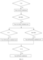
- the method may include: an environment monitoring apparatus performs real-time monitoring on temperature and humidity in a cabinet body 11; and controls turning-on and turning-off of an air conditioner 131 and a direct ventilation unit 132 based on monitored temperature and humidity values.
- the temperature in the cabinet 10 may include three cases. In a first case, the temperature in the cabinet is relatively high, for example, exceeds a first preset temperature threshold. In a second case, the temperature in the cabinet falls between the first preset temperature threshold and a second preset temperature threshold. In a third case, the temperature in the cabinet is lower than the second preset temperature threshold. For the first case and the second case, a refrigerating system 13 is usually used for adjustment. For the third case, no adjustment may be performed.
- the following describes in detail a process of adjusting the temperature and the humidity in the cabinet when the temperature in the cabinet 10 is in the first case.
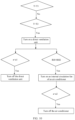
- the controlling turning-on and turning-off of an air conditioner 131 and a direct ventilation unit 132 based on monitored temperature and humidity values may include: determining whether the temperature monitored by the environment monitoring apparatus is higher than the first preset temperature threshold; when the temperature monitored by the environment monitoring apparatus is higher than the first preset temperature threshold, turning on the air conditioner 131; when the air conditioner 131 is in a working state, determining whether humidity monitored by the environment monitoring apparatus is lower than a first preset humidity threshold; and when the humidity monitored by the environment monitoring apparatus is lower than the first preset humidity threshold, turning on the direct ventilation unit 132, so that the direct ventilation unit 132 and the air conditioner 131 increase the humidity in the cabinet in an air mixing manner.
- the method may further include: determining whether a difference between humidity monitored by the environment monitoring apparatus in a first preset time period is lower than a first preset difference; and when the difference between the humidity monitored by the environment monitoring apparatus in the first preset time period is lower than the first preset difference, turning off the direct ventilation unit 132.
- the method may further include: determining whether humidity monitored by the environment monitoring apparatus is higher than a second preset humidity threshold, where the first preset humidity threshold is smaller than the second preset humidity threshold; and when the humidity monitored by the environment monitoring apparatus is higher than the second preset humidity threshold, turning off the direct ventilation unit 132.
- the air conditioner 131 mainly runs to adjust the temperature and the humidity inside the cabinet 10.
- the method may further include: determining whether temperature monitored by the environment monitoring apparatus is lower than the second preset temperature threshold, where the second preset temperature threshold is lower than the first preset temperature threshold; and when the temperature monitored by the environment monitoring apparatus is lower than the second preset temperature threshold, turning off the air conditioner 131.
- a preset temperature threshold is represented by T
- the first preset temperature threshold is represented by T1
- the second preset temperature threshold is represented by T2
- a preset humidity threshold is represented by RH
- a first preset humidity threshold is represented by RH1
- a second preset humidity threshold is represented by RH2
- a preset difference is represented by a, the first preset difference is represented by a1, and a second preset difference is represented by a2.
- both the first preset time period and a second preset time period are 30 min.
- the environment monitoring apparatus when determining, through monitoring, that temperature in the cabinet 10 is higher than T1 at a specific moment, the environment monitoring apparatus turns on the air conditioner 131 to perform refrigeration; when humidity monitored by the monitoring apparatus is lower than RH1, the environment monitoring apparatus turns on the direct ventilation unit 132, so that the direct ventilation unit 132 and the air conditioner 131 increase the humidity in the cabinet in an air mixing manner; and after the air conditioner 131 and the direct ventilation unit 132 work for a period of time, the temperature in the cabinet 10 decreases and the humidity in the cabinet 10 increases, and when a difference between humidity monitored by the environment monitoring apparatus in 30 min is lower than a1, that is, humidity is in a stable state, the environment monitoring apparatus turns off the direct ventilation unit 132.
- the direct ventilation unit 132 when the direct ventilation unit 132 is in an on state, when humidity monitored by the environment monitoring apparatus is greater than RH2, the direct ventilation unit 132 is turned off.
- the air conditioner 131 mainly runs to adjust the temperature and the humidity inside the cabinet 10.
- the air conditioner 131 is turned off.
- the following describes in detail a process of adjusting the temperature and the humidity in the cabinet when the temperature in the cabinet 10 is in the second case.
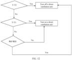
- the controlling turning-on and turning-off of an air conditioner 131 and a direct ventilation unit 132 based on monitored temperature and humidity values may alternatively include: determining whether the temperature monitored by the environment monitoring apparatus is lower than the first preset temperature threshold and higher than the second preset temperature threshold; and when the temperature monitored by the environment monitoring apparatus is lower than the first preset temperature threshold and higher than the second preset temperature threshold, turning on the direct ventilation unit 132, to cool the inside of the cabinet 10 by using the direct ventilation unit 132.
- the method may further include: determining whether a difference between humidity monitored by the environment monitoring apparatus in the first preset time period is lower than the first preset difference; and when the difference between the humidity monitored by the environment monitoring apparatus in the first preset time period is lower than the first preset difference, turning off the direct ventilation unit 132.
- the method may further include: determining whether humidity monitored by the environment monitoring apparatus is higher than the second preset humidity threshold, where the first preset humidity threshold is smaller than the second preset humidity threshold; and when the humidity monitored by the environment monitoring apparatus is higher than the second preset humidity threshold, turning on an internal circulation fan of the air conditioner 131, to decrease the humidity in the cabinet in an air mixing manner by using the direct ventilation unit 132 and the air conditioner 131.
- the method may further include: determining whether a difference between humidity monitored by the environment monitoring apparatus in the second preset time period is lower than the second preset difference; and when the difference between the humidity monitored by the environment monitoring apparatus in the second preset time period is lower than the second preset difference, turning off the air conditioner 131.
- the environment monitoring apparatus when determining, through monitoring, that temperature in the cabinet 10 is lower than T1 and higher than T2 at a specific moment, the environment monitoring apparatus turns on the direct ventilation unit 132 to perform refrigeration; and after the direct ventilation unit 132 works for a period of time, the humidity in the cabinet 10 increases, and when a difference between humidity monitored by the environment monitoring apparatus in the first preset time period is lower than a1, that is, humidity is in a stable state, the environment monitoring apparatus turns off the direct ventilation unit 132.
- the direct ventilation unit 132 when the direct ventilation unit 132 is in an on state, when humidity monitored by the environment monitoring apparatus is greater than RH2, an internal circulation fan of the air conditioner 131 is turned on; and when a difference between humidity monitored by the environment monitoring apparatus in the second preset time period is lower than a2, that is, humidity is in a stable state, the air conditioner 131 is turned off.
- the internal circulation fan of the air conditioner 131 is located inside the cabinet 10.
- the internal circulation fan can enable air in the cabinet to be sequentially circulated, so that hot air in the cabinet 10 can be sequentially blown into the air conditioner 131 for heat exchange.
- humidity of the air is decreased due to refrigeration of the air conditioner 131.
- the first preset time period may be the same as or may be different from the second preset time period.
- the first preset difference may be the same as or may be different from the second preset difference.
- the air conditioner 131 when the temperature is higher than T1, or the temperature falls between T1 and T2 and the humidity is greater than RH2, the air conditioner 131 may be turned on; or when the temperature is not greater than T2, or the temperature falls between T1 and T2 and the humidity is not greater than RH2, the air conditioner 131 may be turned off.
- the direct ventilation unit 132 when the temperature is smaller than T2, or the temperature is not smaller than T1 and the humidity is greater than RH1, the direct ventilation unit 132 may be turned off; or when the humidity is not greater than RH1, or the temperature falls between T1 and T2, the direct ventilation unit 132 may be turned on.
- the turning-on and the turning-off of the air conditioner 131 and the direct ventilation unit 132 are controlled by using two indexes that are the temperature and the humidity, so that the humidity in the cabinet 10 can be adjusted when the temperature in the cabinet 10 is adjusted, and fluctuation of the humidity inside the cabinet 10 can also be prevented, to avoid condensation inside the cabinet.
- the method may further include: determining whether temperature monitored by the environment monitoring apparatus is lower than the second temperature threshold, and determining whether a difference between humidity monitored by the environment monitoring apparatus in the first preset time period is lower than the first preset difference; when the temperature monitored by the environment monitoring apparatus is lower than the second temperature threshold, and the difference between the humidity monitored by the environment monitoring apparatus in the first preset time period is lower than the first preset difference, turning off the air conditioner 131, and also turning off the direct ventilation unit 132.
- the temperature and humidity in the cabinet 10 are in a proper state and do not need to be adjusted.
- only the direct ventilation unit 132 may be turned on to adjust an internal environment of the cabinet 10, so that the internal environment of the cabinet 10 is kept in a proper state.
- the air conditioner 131 is turned on again, and the temperature and humidity in the cabinet 10 are adjusted according to the adjustment steps used when the temperature in the cabinet 10 is in the first case.
Landscapes
- Engineering & Computer Science (AREA)
- Microelectronics & Electronic Packaging (AREA)
- Physics & Mathematics (AREA)
- Thermal Sciences (AREA)
- Aviation & Aerospace Engineering (AREA)
- Air Conditioning Control Device (AREA)
- Cooling Or The Like Of Electrical Apparatus (AREA)
Claims (14)
- Mehrtemperatur-Schaltschrank (10), einen Schrankkörper (11), eine Schranktür (12) und ein Kühlsystem (13) umfassend, wobeidas Kühlsystem (13) eine Klimaanlage (131), eine Direktbelüftungseinheit (132) und eine Umgebungsüberwachungsvorrichtung umfasst,sowohl die Klimaanlage (131) als auch die Direktbelüftungseinheit (132) an der Schranktür (12) angeordnet sind und die Klimaanlage (131) und die Direktbelüftungseinheit (132) in einer Höhenrichtung der Schranktür parallel angeordnet sind,eine Luftführungsanordnung (133) zwischen der Direktbelüftungseinheit (132) und einer Abluftentlüftung (1311) der Klimaanlage (131) angeordnet ist, wobei die Abluftentlüftung (1311) der Klimaanlage (131) zu einer Innenseite des Schrankkörpers (11) weist, unddie Umgebungsüberwachungsvorrichtung sowohl mit der Klimaanlage (131) als auch der Direktbelüftungseinheit (132) verbunden ist und die Umgebungsüberwachungsvorrichtung für Folgendes konfiguriert ist: Überwachen der Temperatur und der Luftfeuchte in dem Schrankkörper (11) und Steuern des An-und Ausschaltens der Klimaanlage (131) und der Direktbelüftungseinheit (132), basierend auf der Temperatur und der Luftfeuchte in dem Schrankkörper (11),wobei die Direktbelüftungseinheit (132) eine Lufteinlasseinheit (1321) und eine Abluftentlüftungseinheit (1322) umfasst unddie Luftführungsanordnung (133) zwischen der Lufteinlasseinheit (1321) und der Abluftentlüftung (1311) der Klimaanlage (131) angeordnet ist,dadurch gekennzeichnet, dass eine Lufteinlasslüftung (1331), ein Luftmischkanal (1332) und eine Mischlufttentlüftung (1333) an der Luftführungsanordnung (133) angeordnet sind,der Luftmischkanal (1332) mit sowohl der Lufteinlasslüftung (1331) als auch der Mischlufttentlüftung (1333) verbunden ist,die Lufteinlasslüftung (1331) mit sowohl der Abluftentlüftung (1311) der Klimaanlage (131) als auch der Lufteinlasseinheit (1321) verbunden ist unddie Mischlufttentlüftung (1333) zur Innenseite des Schranks (10) weist,so dass die Luftführungsanordnung (133) dafür konfiguriert ist, kalte Luft, die von der Abluftentlüftung (1311) der Klimaanlage (131) ausgestoßen wird, mit natürlicher Luft, die von der Lufteinlasseinheit (1321) eintritt, zu mischen.
- Mehrtemperatur-Schaltschrank (10) nach Anspruch 1, wobei eine einzelne Schranktür vorhanden ist,sich die Lufteinlasseinheit (1321) unterhalb der Klimaanlage (131) befindet unddie Abluftentlüftungseinheit (1322) oberhalb der Klimaanlage (131) angeordnet ist.
- Mehrtemperatur-Schaltschrank (10) nach einem der Ansprüche 1 bis 2, wobei die Luftführungsanordnung (133) eine tonnenartige Struktur aufweist,die Lufteinlasslüftung (1331) eine erste Lufteinlasslüftung (1331a) und eine zweite Lufteinlasslüftung (1331b) umfasst,die erste Lufteinlasslüftung (1331a) mit der Abluftentlüftung (1311) der Klimaanlage (131) verbunden ist unddie zweite Lufteinlasslüftung (1331b) mit der Lufteinlasseinheit (1321) verbunden ist.
- Mehrtemperatur-Schaltschrank (10), einen Schrankkörper (11), eine erste Schranktür (121) und eine zweite Schranktür (122), die gegenüber angeordnet sind, und ein Kühlsystem (13) umfassend,wobei das Kühlsystem (13) zwei Klimaanlagen (131), eine Direktbelüftungseinheit (132) und eine Umgebungsüberwachungsvorrichtung umfasst,die Umgebungsüberwachungsvorrichtung mit beiden Klimaanlagen (131) und der Direktbelüftungseinheit (132) verbunden ist und die Umgebungsüberwachungsvorrichtung für Folgendes konfiguriert ist: Überwachen der Temperatur und der Luftfeuchte in dem Schrankkörper (11) und Steuern des An-und Ausschaltens der Klimaanlagen (131) und der Direktbelüftungseinheit (132), basierend auf der Temperatur und der Luftfeuchte in dem Schrankkörper (11), wobei die Direktbelüftungseinheit (132) eine Lufteinlasseinheit (1321) und eine Abluftentlüftungseinheit (1322) umfasst undeine der Klimaanlagen (131) und die Lufteinlasseinheit (1321) an der ersten Schranktür (121) angeordnet sind und sich die Lufteinlasseinheit (1321) unterhalb der Klimaanlage (131) an der ersten Schranktür (121) befindet,eine andere der Klimaanlagen (131) und die Abluftentlüftungseinheit (1322) an der zweiten Schranktür (122) angeordnet sind und sich die Abluftentlüftungseinheit (1322) oberhalb der Klimaanlage (131) an der zweiten Schranktür (122) befindet, undeine Luftführungsanordnung (133) zwischen einer Abluftentlüftung (1311) der Klimaanlage (131) an der ersten Schranktür (121) und der Lufteinlasseinheit (1321) an der ersten Schranktür (121) angeordnet ist, wobei die Abluftentlüftung (1311) der Klimaanlage (131) an der ersten Schranktür (121) zu einer Innenseite des Schrankkörpers (11) weist,wobei eine Lufteinlasslüftung (1331), ein Luftmischkanal (1332) und eine Mischluftentlüftung (1333) an der Luftführungsanordnung (133) angeordnet sind, der Luftmischkanal (1332) mit sowohl der Lufteinlasslüftung (1331) als auch der Mischluftentlüftung (1333) verbunden ist,die Lufteinlasslüftung (1331) mit sowohl der Abluftentlüftung (1311) der Klimaanlage (131) an der ersten Schranktür (121) als auch der Lufteinlasseinheit (1321) verbunden ist unddie Mischluftentlüftung (1333) zur Innenseite des Schranks (10) weist,so dass die Luftführungsanordnung (133) dafür konfiguriert ist, kalte Luft, die von der Abluftentlüftung (1311) der Klimaanlage (131) an der ersten Schranktür (121) ausgestoßen wird, mit natürlicher Luft, die von der Lufteinlasseinheit (1321) eintritt, zu mischen.
- Mehrtemperatur-Schaltschrank (11) nach Anspruch 4, wobei die Luftführungsanordnung (133) eine tonnenartige Struktur aufweist,die Lufteinlasslüftung (1331) eine erste Lufteinlasslüftung (1331a) und eine zweite Lufteinlasslüftung (1331b) umfasst,die erste Lufteinlasslüftung (1331a) mit der Abluftentlüftung (1311) der Klimaanlage (131) an der ersten Schranktür (121) verbunden ist unddie zweite Lufteinlasslüftung (1331b) mit der Lufteinlasseinheit (1321) verbunden ist.
- Mehrtemperatur-Schaltschrank (10) nach einem der Ansprüche 1 bis 5, wobei ein Material der Luftführungsanordnung (133) Metallblech oder Kunststoff ist.
- Mehrtemperatur-Schaltschrank (10) nach einem der Ansprüche 1 bis 6, wobei die Umgebungsüberwachungsvorrichtung eine Temperaturüberwachungskomponente und eine Luftfeuchteüberwachungskomponente umfasst,die Temperaturüberwachungskomponente konfiguriert ist, die Temperatur in dem Schrankkörper (11) zu überwachen, unddie Luftfeuchteüberwachungskomponente konfiguriert ist, die Luftfeuchte in dem Schrankkörper (11) zu überwachen.
- Zeitplanungsverfahren für einen Mehrtemperatur-Schaltschrank, das verwendet wird, um die Temperatur und die Luftfeuchte in dem Mehrtemperatur-Schaltschrank nach einem der Ansprüche 1 bis 3 zu justieren, wobei das Verfahren Folgendes umfasst:Durchführen einer Echtzeitüberwachung der Temperatur und der Luftfeuchte in einem Schrankkörper durch eine Umgebungsüberwachungsvorrichtung undSteuern des An- und Ausschaltens einer Klimaanlage und einer Direktbelüftungseinheit, basierend auf Überwachungswerten der Temperatur und der Luftfeuchte.
- Zeitplanungsverfahren für einen Mehrtemperatur-Schaltschrank nach Anspruch 8, wobei das Steuern des An- und Ausschaltens einer Klimaanlage und einer Direktbelüftungseinheit, basierend auf Überwachungswerten der Temperatur und der Luftfeuchte, Folgendes umfasst:Bestimmen, ob die Temperatur, die von der Umgebungsüberwachungsvorrichtung überwacht wird, höher als ein erster voreingestellter Temperaturgrenzwert ist,wenn die Temperatur, die von der Umgebungsüberwachungsvorrichtung überwacht wird, höher als der erste voreingestellte Temperaturgrenzwert ist, Anschalten der Klimaanlage,wenn sich die Klimaanlage in einem Arbeitszustand befindet, Bestimmen, ob die Luftfeuchte, die von der Umgebungsüberwachungsvorrichtung überwacht wird, niedriger als ein erster voreingestellter Luftfeuchtegrenzwert ist, undwenn die Luftfeuchte, die von der Umgebungsüberwachungsvorrichtung überwacht wird, niedriger als der erste voreingestellte Luftfeuchtegrenzwert ist, Anschalten der Direktbelüftungseinheit, so dass die Direktbelüftungseinheit und die Klimaanlage die Luftfeuchte in dem Schrank in einer luftmischenden Weise erhöhen.
- Zeitplanungsverfahren für einen Mehrtemperatur-Schaltschrank nach Anspruch 8, wobei das Steuern des An- und Ausschaltens einer Klimaanlage und einer Direktbelüftungseinheit, basierend auf Überwachungswerten der Temperatur und der Luftfeuchte, Folgendes umfasst:Bestimmen, ob die Temperatur, die von der Umgebungsüberwachungsvorrichtung überwacht wird, niedriger als der erste voreingestellte Temperaturgrenzwert und höher als ein zweiter voreingestellter Temperaturgrenzwert ist, wobei der zweite Temperaturgrenzwert niedriger als der erste Temperaturgrenzwert ist, undwenn die Temperatur, die von der Umgebungsüberwachungsvorrichtung überwacht wird, niedriger als der erste voreingestellte Temperaturgrenzwert und höher als der zweite voreingestellte Temperaturgrenzwert ist, Anschalten der Direktbelüftungseinheit, um das Klima in dem Schrank mit Hilfe der Direktbelüftungseinheit zu justieren.
- Zeitplanungsverfahren für einen Mehrtemperatur-Schaltschrank nach einem der Ansprüche 9 oder 10, wobei das Verfahren nach dem Anschalten der Direktbelüftungseinheit ferner Folgendes umfasst:Bestimmen, ob eine Differenz zwischen der Luftfeuchte, die von der Umgebungsüberwachungsvorrichtung überwacht wird, in einer ersten voreingestellten Zeitspanne geringer als eine erste voreingestellte Differenz ist, undwenn die Differenz zwischen der Luftfeuchte, die von der Umgebungsüberwachungsvorrichtung überwacht wird, in der ersten voreingestellten Zeitspanne geringer als die erste voreingestellte Differenz ist, Ausschalten der Direktbelüftungseinheit.
- Zeitplanungsverfahren für einen Mehrtemperatur-Schaltschrank nach Anspruch 9, wobei das Verfahren nach dem Anschalten der Direktbelüftungseinheit ferner Folgendes umfasst:Bestimmen, ob die Luftfeuchte, die von der Umgebungsüberwachungsvorrichtung überwacht wird, höher als ein zweiter voreingestellter Luftfeuchtegrenzwert ist, wobei der erste voreingestellte Luftfeuchtegrenzwert kleiner als der zweite voreingestellte Luftfeuchtegrenzwert ist, undwenn die Luftfeuchte, die von der Umgebungsüberwachungsvorrichtung überwacht wird, höher als der zweite voreingestellte Luftfeuchtegrenzwert ist, Ausschalten der Direktbelüftungseinheit, um die Luftfeuchte in dem Schrank durch Laufenlassen der Klimaanlage zu senken.
- Zeitplanungsverfahren für einen Mehrtemperatur-Schaltschrank nach Anspruch 12, wobei das Verfahren nach dem Ausschalten der Direktbelüftungseinheit ferner Folgendes umfasst:Bestimmen, ob die Temperatur, die von der Umgebungsüberwachungsvorrichtung überwacht wird, niedriger als ein zweiter voreingestellter Temperaturgrenzwert ist, wobei der zweite voreingestellte Temperaturgrenzwert niedriger als der erste voreingestellte Temperaturgrenzwert ist, undwenn die Temperatur, die von der Umgebungsüberwachungsvorrichtung überwacht wird, niedriger als der zweite voreingestellte Temperaturgrenzwert ist, Ausschalten der Klimaanlage.
- Zeitplanungsverfahren für einen Mehrtemperatur-Schaltschrank nach Anspruch 10, wobei das Verfahren nach dem Anschalten der Direktbelüftungseinheit ferner Folgendes umfasst:Bestimmen, ob die Luftfeuchte, die von der Umgebungsüberwachungsvorrichtung überwacht wird, höher als ein zweiter voreingestellter Luftfeuchtegrenzwert ist, wobei der erste voreingestellte Luftfeuchtegrenzwert kleiner als der zweite voreingestellte Luftfeuchtegrenzwert ist, undwenn die Luftfeuchte, die von der Umgebungsüberwachungsvorrichtung überwacht wird, höher als der zweite voreingestellte Luftfeuchtegrenzwert ist, Anschalten eines internen Zirkulationsgebläses der Klimaanlage, um die Luftfeuchte in dem Schrank mit Hilfe der Direktbelüftungseinheit und der Klimaanlage in einer luftmischenden Weise zu senken.
Applications Claiming Priority (1)
| Application Number | Priority Date | Filing Date | Title |
|---|---|---|---|
| CN202110374514.3A CN113301771B (zh) | 2021-04-07 | 2021-04-07 | 一种多温控机柜以及其调度方法 |
Publications (2)
| Publication Number | Publication Date |
|---|---|
| EP4072256A1 EP4072256A1 (de) | 2022-10-12 |
| EP4072256B1 true EP4072256B1 (de) | 2024-03-06 |
Family
ID=77319443
Family Applications (1)
| Application Number | Title | Priority Date | Filing Date |
|---|---|---|---|
| EP22166765.2A Active EP4072256B1 (de) | 2021-04-07 | 2022-04-05 | Mehrtemperaturkontrollschrank und planungsverfahren für einen mehrtemperatursteuerungsschrank |
Country Status (4)
| Country | Link |
|---|---|
| US (1) | US12193175B2 (de) |
| EP (1) | EP4072256B1 (de) |
| CN (1) | CN113301771B (de) |
| WO (1) | WO2022213635A1 (de) |
Families Citing this family (9)
| Publication number | Priority date | Publication date | Assignee | Title |
|---|---|---|---|---|
| CN215819125U (zh) * | 2021-01-15 | 2022-02-11 | 华为数字能源技术有限公司 | 一种温控机柜及通信系统 |
| CN113301771B (zh) * | 2021-04-07 | 2024-04-09 | 华为数字能源技术有限公司 | 一种多温控机柜以及其调度方法 |
| CN115279128B (zh) * | 2022-07-22 | 2025-04-25 | 珠海格力电器股份有限公司 | 一种调控机柜温度的系统及方法 |
| CN115226377A (zh) * | 2022-07-25 | 2022-10-21 | 珠海格力电器股份有限公司 | 一种机柜空调及其控制方法、控制装置 |
| CN115666097B (zh) * | 2022-11-07 | 2026-02-13 | 中国建设银行股份有限公司 | 机房温度控制方法及装置、存储介质及电子设备 |
| CN115561997A (zh) * | 2022-11-17 | 2023-01-03 | 湖南大学 | 一种基于高可靠性柜门设计的户外通信机柜节能控制方法 |
| CN115864186B (zh) * | 2022-12-05 | 2025-07-11 | 武汉武开电力工程设备有限公司 | 一种低压开关柜温控装置及方法 |
| CN116414165A (zh) * | 2023-05-04 | 2023-07-11 | 立思高仪器设备(南京)有限公司 | 一种制冷恒温恒湿控制系统及控制方法 |
| CN117674541B (zh) * | 2023-10-30 | 2024-11-08 | 湖南科瑞变流电气股份有限公司 | 一种智能控温的整流柜及其工作方法 |
Citations (1)
| Publication number | Priority date | Publication date | Assignee | Title |
|---|---|---|---|---|
| CN203661433U (zh) * | 2013-12-09 | 2014-06-18 | 东莞市湘华五金科技有限公司 | 带热交换温控单元机柜 |
Family Cites Families (38)
| Publication number | Priority date | Publication date | Assignee | Title |
|---|---|---|---|---|
| JP4085649B2 (ja) * | 2002-02-25 | 2008-05-14 | 日本電気株式会社 | 電子装置の結露防止構造及び結露防止方法 |
| LU90926B1 (en) * | 2002-05-28 | 2003-12-01 | Uniflair Int Sa | Compact air-cooling device for a closed technical cabinet |
| KR101265605B1 (ko) * | 2006-07-04 | 2013-05-22 | 엘지전자 주식회사 | 의류 처리 장치 |
| CN101506590B (zh) * | 2006-09-01 | 2012-03-14 | 艾利森电话股份有限公司 | 电气设备的湿度控制 |
| US20080122993A1 (en) * | 2006-11-29 | 2008-05-29 | Sanyo Electric Co., Ltd. | Television image receiver |
| JP2011029341A (ja) * | 2009-07-23 | 2011-02-10 | Nec Corp | 電子機器冷却システム及び電子機器冷却方法,プログラム |
| TWI425346B (zh) * | 2009-12-17 | 2014-02-01 | Delta Electronics Inc | 貨櫃式資料中心之環境調節系統及調節方法 |
| CN101827506B (zh) * | 2010-05-04 | 2013-05-22 | 北京金秋果实电子科技有限公司 | 智能机柜 |
| CN102573404A (zh) * | 2010-12-31 | 2012-07-11 | 苏州昆拓热控系统股份有限公司 | 机柜专用空调器及其控制方法 |
| CN202350249U (zh) * | 2011-12-02 | 2012-07-25 | 温州市创力电子有限公司 | 基站自排热节能控制系统 |
| CN102662422B (zh) * | 2012-05-10 | 2014-11-05 | 华为技术有限公司 | 机柜控制方法和通信装置 |
| JP2013258166A (ja) * | 2012-06-11 | 2013-12-26 | Hitachi Ltd | 電子機器装置およびその筺体 |
| CN103326258A (zh) * | 2013-07-08 | 2013-09-25 | 万能亿自动化科技(苏州)有限公司 | 一种能防凝露的密封开关柜 |
| CN203775582U (zh) * | 2014-01-17 | 2014-08-13 | 上海沃姆珂尔环境技术有限公司 | 低能耗控温机柜 |
| CN103904568B (zh) * | 2014-03-17 | 2016-08-31 | 中国能源建设集团陕西省电力设计院有限公司 | 一种汇控柜通风除湿系统及其方法 |
| KR101684054B1 (ko) * | 2015-01-21 | 2016-12-20 | 엘지전자 주식회사 | 냉장고 및 그 제어방법 |
| CN204539637U (zh) * | 2015-03-27 | 2015-08-05 | 国家电网公司 | 电力户外柜温控系统 |
| CN106163217B (zh) * | 2015-04-13 | 2020-06-26 | 台达电子工业股份有限公司 | 调温机柜 |
| CN106507635B (zh) * | 2015-09-07 | 2019-12-20 | 中兴通讯股份有限公司 | 一种机柜 |
| CN106594930B (zh) * | 2016-12-19 | 2022-05-10 | 珠海格力电器股份有限公司 | 一种节能机房空调系统 |
| CN107027272A (zh) * | 2017-05-04 | 2017-08-08 | 深圳市共济科技股份有限公司 | 一种数据中心机柜装置及其应急散热方法 |
| CN206685778U (zh) * | 2017-05-16 | 2017-11-28 | 石狮市新卯自动化设备有限公司 | 一种具有空气交换装置的控制柜 |
| CN107374075A (zh) * | 2017-07-13 | 2017-11-24 | 四川云物益邦科技有限公司 | 适用于不同存储环境的档案存储设备 |
| CN207284039U (zh) * | 2017-10-25 | 2018-04-27 | 国网浙江乐清市供电有限公司 | 一种温湿度控制的通信柜 |
| CN107734931A (zh) * | 2017-10-27 | 2018-02-23 | 国家电网公司 | 具有精准控温及独立除湿功能的电气设备组件柜 |
| RU2744780C1 (ru) * | 2017-11-30 | 2021-03-15 | Фраматом Гмбх | Система вентиляции и кондиционирования воздуха с пассивным режимом аварийного охлаждения |
| US20190198834A1 (en) * | 2017-12-21 | 2019-06-27 | Vertiv Energy Systems, Inc. | Telecommunications equipment cabinets including isolated and removable battery box assemblies |
| CN108281913B (zh) * | 2018-02-08 | 2023-10-03 | 湖北中巽泰科技有限公司 | 复叠式循环通道降温除湿防凝露电气设备保障系统及方法 |
| CN108565730A (zh) * | 2018-04-28 | 2018-09-21 | 无锡赛孚电力环境控制设备有限公司 | 一种变电站二次设备预制舱的智能通风降温除湿方法 |
| CN208227564U (zh) * | 2018-05-28 | 2018-12-11 | 郑州云海信息技术有限公司 | 一种集装箱数据中心散热系统 |
| CN208580995U (zh) * | 2018-07-25 | 2019-03-05 | 国网浙江嘉善县供电有限公司 | 一种环网柜制冷除湿装置 |
| US11045011B2 (en) * | 2019-01-09 | 2021-06-29 | Virgil Venditto | Apparatus, system, and method for providing a climate controlled environment surrounding a bed for healthy sleep |
| FR3097696B1 (fr) | 2019-06-24 | 2021-07-09 | Schneider Electric Ind Sas | Armoire électrique avec bloc de conditionnement d’air |
| JP7477739B2 (ja) * | 2019-06-26 | 2024-05-02 | ダイキン工業株式会社 | 外気処理装置及び空調システム |
| KR102638178B1 (ko) * | 2019-09-06 | 2024-02-16 | 엘지전자 주식회사 | 공기조화기의 실내기 |
| CN111023283A (zh) * | 2019-11-07 | 2020-04-17 | 毛军光 | 一种立式空调 |
| CN212086674U (zh) * | 2020-05-06 | 2020-12-04 | 维谛技术有限公司 | 一种机柜门凝露消除设备和机柜 |
| CN113301771B (zh) * | 2021-04-07 | 2024-04-09 | 华为数字能源技术有限公司 | 一种多温控机柜以及其调度方法 |
-
2021
- 2021-04-07 CN CN202110374514.3A patent/CN113301771B/zh active Active
- 2021-12-06 WO PCT/CN2021/135692 patent/WO2022213635A1/zh not_active Ceased
-
2022
- 2022-04-01 US US17/711,240 patent/US12193175B2/en active Active
- 2022-04-05 EP EP22166765.2A patent/EP4072256B1/de active Active
Patent Citations (1)
| Publication number | Priority date | Publication date | Assignee | Title |
|---|---|---|---|---|
| CN203661433U (zh) * | 2013-12-09 | 2014-06-18 | 东莞市湘华五金科技有限公司 | 带热交换温控单元机柜 |
Also Published As
| Publication number | Publication date |
|---|---|
| CN113301771B (zh) | 2024-04-09 |
| EP4072256A1 (de) | 2022-10-12 |
| US12193175B2 (en) | 2025-01-07 |
| US20220330442A1 (en) | 2022-10-13 |
| WO2022213635A1 (zh) | 2022-10-13 |
| CN113301771A (zh) | 2021-08-24 |
Similar Documents
| Publication | Publication Date | Title |
|---|---|---|
| EP4072256B1 (de) | Mehrtemperaturkontrollschrank und planungsverfahren für einen mehrtemperatursteuerungsschrank | |
| US10292313B2 (en) | Rackmount cooling system | |
| EP1367331B1 (de) | Kompaktklimagerät für einen Schaltschrank | |
| US8621884B2 (en) | AC unit with economizer and sliding damper assembly | |
| EP2977243B1 (de) | Klimaanlage für ein fahrzeug | |
| CN113405161A (zh) | 空调器及其控制方法、计算机可读存储介质 | |
| EP3882529B1 (de) | Ausseneinheit für klimaanlage | |
| EP1217879B1 (de) | Verfahren und Einrichtung zur thermischen Konditionierung von elektronische augruppen enthaltenden Schränken | |
| EP2098797A1 (de) | Klimaanlage | |
| EP3051216B1 (de) | Ausseneinheit einer klimaanlage und klimaanlage | |
| CN219106866U (zh) | 一种具有通风机构的配电柜 | |
| US6301914B1 (en) | Room air conditioner having outdoor power cord | |
| CN209806322U (zh) | 一种具有新风通道的机柜空调 | |
| JP2009133617A (ja) | 空調システム | |
| EP3848642A1 (de) | Kondensationsschutzschale | |
| CZ12701U1 (cs) | Prostorový prvek k ochraně vysílačového zařízení nebo jiných elektrotechnických přístrojů pro telekomunikaci | |
| CN214204523U (zh) | 一种自动调整室内环境的配电室 | |
| CN223710055U (zh) | 一种变频冷水机 | |
| CN113438871B (zh) | 机房及机房温度控制方法 | |
| CN222187158U (zh) | 水冷直膨式空调 | |
| CN216123420U (zh) | 一种水冷网络智能型电磁屏蔽机柜 | |
| CN212085590U (zh) | 一种能够提高散热能力的电气柜 | |
| CN220287612U (zh) | 电控盒组件、室外机及空调器 | |
| CN215543592U (zh) | 一种具有智能控温功能的实验室通风橱柜 | |
| EP1471748A1 (de) | Integrierter Nutzschrank für eine Fernsprechvermittlungsanlage |
Legal Events
| Date | Code | Title | Description |
|---|---|---|---|
| PUAI | Public reference made under article 153(3) epc to a published international application that has entered the european phase |
Free format text: ORIGINAL CODE: 0009012 |
|
| STAA | Information on the status of an ep patent application or granted ep patent |
Free format text: STATUS: REQUEST FOR EXAMINATION WAS MADE |
|
| 17P | Request for examination filed |
Effective date: 20220405 |
|
| AK | Designated contracting states |
Kind code of ref document: A1 Designated state(s): AL AT BE BG CH CY CZ DE DK EE ES FI FR GB GR HR HU IE IS IT LI LT LU LV MC MK MT NL NO PL PT RO RS SE SI SK SM TR |
|
| STAA | Information on the status of an ep patent application or granted ep patent |
Free format text: STATUS: EXAMINATION IS IN PROGRESS |
|
| 17Q | First examination report despatched |
Effective date: 20230515 |
|
| GRAP | Despatch of communication of intention to grant a patent |
Free format text: ORIGINAL CODE: EPIDOSNIGR1 |
|
| STAA | Information on the status of an ep patent application or granted ep patent |
Free format text: STATUS: GRANT OF PATENT IS INTENDED |
|
| INTG | Intention to grant announced |
Effective date: 20230926 |
|
| P01 | Opt-out of the competence of the unified patent court (upc) registered |
Effective date: 20231130 |
|
| GRAS | Grant fee paid |
Free format text: ORIGINAL CODE: EPIDOSNIGR3 |
|
| GRAA | (expected) grant |
Free format text: ORIGINAL CODE: 0009210 |
|
| STAA | Information on the status of an ep patent application or granted ep patent |
Free format text: STATUS: THE PATENT HAS BEEN GRANTED |
|
| AK | Designated contracting states |
Kind code of ref document: B1 Designated state(s): AL AT BE BG CH CY CZ DE DK EE ES FI FR GB GR HR HU IE IS IT LI LT LU LV MC MK MT NL NO PL PT RO RS SE SI SK SM TR |
|
| REG | Reference to a national code |
Ref country code: CH Ref legal event code: EP |
|
| REG | Reference to a national code |
Ref country code: IE Ref legal event code: FG4D |
|
| REG | Reference to a national code |
Ref country code: DE Ref legal event code: R096 Ref document number: 602022002206 Country of ref document: DE |
|
| REG | Reference to a national code |
Ref country code: LT Ref legal event code: MG9D |
|
| PG25 | Lapsed in a contracting state [announced via postgrant information from national office to epo] |
Ref country code: LT Free format text: LAPSE BECAUSE OF FAILURE TO SUBMIT A TRANSLATION OF THE DESCRIPTION OR TO PAY THE FEE WITHIN THE PRESCRIBED TIME-LIMIT Effective date: 20240306 |
|
| REG | Reference to a national code |
Ref country code: NL Ref legal event code: MP Effective date: 20240306 |
|
| PG25 | Lapsed in a contracting state [announced via postgrant information from national office to epo] |
Ref country code: GR Free format text: LAPSE BECAUSE OF FAILURE TO SUBMIT A TRANSLATION OF THE DESCRIPTION OR TO PAY THE FEE WITHIN THE PRESCRIBED TIME-LIMIT Effective date: 20240607 |
|
| PG25 | Lapsed in a contracting state [announced via postgrant information from national office to epo] |
Ref country code: HR Free format text: LAPSE BECAUSE OF FAILURE TO SUBMIT A TRANSLATION OF THE DESCRIPTION OR TO PAY THE FEE WITHIN THE PRESCRIBED TIME-LIMIT Effective date: 20240306 Ref country code: RS Free format text: LAPSE BECAUSE OF FAILURE TO SUBMIT A TRANSLATION OF THE DESCRIPTION OR TO PAY THE FEE WITHIN THE PRESCRIBED TIME-LIMIT Effective date: 20240606 |
|
| PG25 | Lapsed in a contracting state [announced via postgrant information from national office to epo] |
Ref country code: ES Free format text: LAPSE BECAUSE OF FAILURE TO SUBMIT A TRANSLATION OF THE DESCRIPTION OR TO PAY THE FEE WITHIN THE PRESCRIBED TIME-LIMIT Effective date: 20240306 |
|
| PG25 | Lapsed in a contracting state [announced via postgrant information from national office to epo] |
Ref country code: RS Free format text: LAPSE BECAUSE OF FAILURE TO SUBMIT A TRANSLATION OF THE DESCRIPTION OR TO PAY THE FEE WITHIN THE PRESCRIBED TIME-LIMIT Effective date: 20240606 Ref country code: NO Free format text: LAPSE BECAUSE OF FAILURE TO SUBMIT A TRANSLATION OF THE DESCRIPTION OR TO PAY THE FEE WITHIN THE PRESCRIBED TIME-LIMIT Effective date: 20240606 Ref country code: LT Free format text: LAPSE BECAUSE OF FAILURE TO SUBMIT A TRANSLATION OF THE DESCRIPTION OR TO PAY THE FEE WITHIN THE PRESCRIBED TIME-LIMIT Effective date: 20240306 Ref country code: HR Free format text: LAPSE BECAUSE OF FAILURE TO SUBMIT A TRANSLATION OF THE DESCRIPTION OR TO PAY THE FEE WITHIN THE PRESCRIBED TIME-LIMIT Effective date: 20240306 Ref country code: GR Free format text: LAPSE BECAUSE OF FAILURE TO SUBMIT A TRANSLATION OF THE DESCRIPTION OR TO PAY THE FEE WITHIN THE PRESCRIBED TIME-LIMIT Effective date: 20240607 Ref country code: FI Free format text: LAPSE BECAUSE OF FAILURE TO SUBMIT A TRANSLATION OF THE DESCRIPTION OR TO PAY THE FEE WITHIN THE PRESCRIBED TIME-LIMIT Effective date: 20240306 Ref country code: ES Free format text: LAPSE BECAUSE OF FAILURE TO SUBMIT A TRANSLATION OF THE DESCRIPTION OR TO PAY THE FEE WITHIN THE PRESCRIBED TIME-LIMIT Effective date: 20240306 Ref country code: BG Free format text: LAPSE BECAUSE OF FAILURE TO SUBMIT A TRANSLATION OF THE DESCRIPTION OR TO PAY THE FEE WITHIN THE PRESCRIBED TIME-LIMIT Effective date: 20240306 |
|
| REG | Reference to a national code |
Ref country code: AT Ref legal event code: MK05 Ref document number: 1664802 Country of ref document: AT Kind code of ref document: T Effective date: 20240306 |
|
| PG25 | Lapsed in a contracting state [announced via postgrant information from national office to epo] |
Ref country code: SE Free format text: LAPSE BECAUSE OF FAILURE TO SUBMIT A TRANSLATION OF THE DESCRIPTION OR TO PAY THE FEE WITHIN THE PRESCRIBED TIME-LIMIT Effective date: 20240306 Ref country code: LV Free format text: LAPSE BECAUSE OF FAILURE TO SUBMIT A TRANSLATION OF THE DESCRIPTION OR TO PAY THE FEE WITHIN THE PRESCRIBED TIME-LIMIT Effective date: 20240306 |
|
| PG25 | Lapsed in a contracting state [announced via postgrant information from national office to epo] |
Ref country code: NL Free format text: LAPSE BECAUSE OF FAILURE TO SUBMIT A TRANSLATION OF THE DESCRIPTION OR TO PAY THE FEE WITHIN THE PRESCRIBED TIME-LIMIT Effective date: 20240306 |
|
| PG25 | Lapsed in a contracting state [announced via postgrant information from national office to epo] |
Ref country code: NL Free format text: LAPSE BECAUSE OF FAILURE TO SUBMIT A TRANSLATION OF THE DESCRIPTION OR TO PAY THE FEE WITHIN THE PRESCRIBED TIME-LIMIT Effective date: 20240306 |
|
| PG25 | Lapsed in a contracting state [announced via postgrant information from national office to epo] |
Ref country code: IS Free format text: LAPSE BECAUSE OF FAILURE TO SUBMIT A TRANSLATION OF THE DESCRIPTION OR TO PAY THE FEE WITHIN THE PRESCRIBED TIME-LIMIT Effective date: 20240706 |
|
| PG25 | Lapsed in a contracting state [announced via postgrant information from national office to epo] |
Ref country code: SM Free format text: LAPSE BECAUSE OF FAILURE TO SUBMIT A TRANSLATION OF THE DESCRIPTION OR TO PAY THE FEE WITHIN THE PRESCRIBED TIME-LIMIT Effective date: 20240306 Ref country code: PT Free format text: LAPSE BECAUSE OF FAILURE TO SUBMIT A TRANSLATION OF THE DESCRIPTION OR TO PAY THE FEE WITHIN THE PRESCRIBED TIME-LIMIT Effective date: 20240708 |
|
| PG25 | Lapsed in a contracting state [announced via postgrant information from national office to epo] |
Ref country code: CZ Free format text: LAPSE BECAUSE OF FAILURE TO SUBMIT A TRANSLATION OF THE DESCRIPTION OR TO PAY THE FEE WITHIN THE PRESCRIBED TIME-LIMIT Effective date: 20240306 Ref country code: EE Free format text: LAPSE BECAUSE OF FAILURE TO SUBMIT A TRANSLATION OF THE DESCRIPTION OR TO PAY THE FEE WITHIN THE PRESCRIBED TIME-LIMIT Effective date: 20240306 |
|
| PG25 | Lapsed in a contracting state [announced via postgrant information from national office to epo] |
Ref country code: AT Free format text: LAPSE BECAUSE OF FAILURE TO SUBMIT A TRANSLATION OF THE DESCRIPTION OR TO PAY THE FEE WITHIN THE PRESCRIBED TIME-LIMIT Effective date: 20240306 |
|
| PG25 | Lapsed in a contracting state [announced via postgrant information from national office to epo] |
Ref country code: PL Free format text: LAPSE BECAUSE OF FAILURE TO SUBMIT A TRANSLATION OF THE DESCRIPTION OR TO PAY THE FEE WITHIN THE PRESCRIBED TIME-LIMIT Effective date: 20240306 |
|
| PG25 | Lapsed in a contracting state [announced via postgrant information from national office to epo] |
Ref country code: SK Free format text: LAPSE BECAUSE OF FAILURE TO SUBMIT A TRANSLATION OF THE DESCRIPTION OR TO PAY THE FEE WITHIN THE PRESCRIBED TIME-LIMIT Effective date: 20240306 |
|
| PG25 | Lapsed in a contracting state [announced via postgrant information from national office to epo] |
Ref country code: SM Free format text: LAPSE BECAUSE OF FAILURE TO SUBMIT A TRANSLATION OF THE DESCRIPTION OR TO PAY THE FEE WITHIN THE PRESCRIBED TIME-LIMIT Effective date: 20240306 Ref country code: SK Free format text: LAPSE BECAUSE OF FAILURE TO SUBMIT A TRANSLATION OF THE DESCRIPTION OR TO PAY THE FEE WITHIN THE PRESCRIBED TIME-LIMIT Effective date: 20240306 Ref country code: RO Free format text: LAPSE BECAUSE OF FAILURE TO SUBMIT A TRANSLATION OF THE DESCRIPTION OR TO PAY THE FEE WITHIN THE PRESCRIBED TIME-LIMIT Effective date: 20240306 Ref country code: PT Free format text: LAPSE BECAUSE OF FAILURE TO SUBMIT A TRANSLATION OF THE DESCRIPTION OR TO PAY THE FEE WITHIN THE PRESCRIBED TIME-LIMIT Effective date: 20240708 Ref country code: PL Free format text: LAPSE BECAUSE OF FAILURE TO SUBMIT A TRANSLATION OF THE DESCRIPTION OR TO PAY THE FEE WITHIN THE PRESCRIBED TIME-LIMIT Effective date: 20240306 Ref country code: IS Free format text: LAPSE BECAUSE OF FAILURE TO SUBMIT A TRANSLATION OF THE DESCRIPTION OR TO PAY THE FEE WITHIN THE PRESCRIBED TIME-LIMIT Effective date: 20240706 Ref country code: EE Free format text: LAPSE BECAUSE OF FAILURE TO SUBMIT A TRANSLATION OF THE DESCRIPTION OR TO PAY THE FEE WITHIN THE PRESCRIBED TIME-LIMIT Effective date: 20240306 Ref country code: CZ Free format text: LAPSE BECAUSE OF FAILURE TO SUBMIT A TRANSLATION OF THE DESCRIPTION OR TO PAY THE FEE WITHIN THE PRESCRIBED TIME-LIMIT Effective date: 20240306 Ref country code: AT Free format text: LAPSE BECAUSE OF FAILURE TO SUBMIT A TRANSLATION OF THE DESCRIPTION OR TO PAY THE FEE WITHIN THE PRESCRIBED TIME-LIMIT Effective date: 20240306 |
|
| PG25 | Lapsed in a contracting state [announced via postgrant information from national office to epo] |
Ref country code: IT Free format text: LAPSE BECAUSE OF FAILURE TO SUBMIT A TRANSLATION OF THE DESCRIPTION OR TO PAY THE FEE WITHIN THE PRESCRIBED TIME-LIMIT Effective date: 20240306 |
|
| REG | Reference to a national code |
Ref country code: DE Ref legal event code: R097 Ref document number: 602022002206 Country of ref document: DE |
|
| PG25 | Lapsed in a contracting state [announced via postgrant information from national office to epo] |
Ref country code: LU Free format text: LAPSE BECAUSE OF NON-PAYMENT OF DUE FEES Effective date: 20240405 |
|
| REG | Reference to a national code |
Ref country code: BE Ref legal event code: MM Effective date: 20240430 |
|
| PG25 | Lapsed in a contracting state [announced via postgrant information from national office to epo] |
Ref country code: LU Free format text: LAPSE BECAUSE OF NON-PAYMENT OF DUE FEES Effective date: 20240405 Ref country code: IT Free format text: LAPSE BECAUSE OF FAILURE TO SUBMIT A TRANSLATION OF THE DESCRIPTION OR TO PAY THE FEE WITHIN THE PRESCRIBED TIME-LIMIT Effective date: 20240306 |
|
| PG25 | Lapsed in a contracting state [announced via postgrant information from national office to epo] |
Ref country code: MC Free format text: LAPSE BECAUSE OF FAILURE TO SUBMIT A TRANSLATION OF THE DESCRIPTION OR TO PAY THE FEE WITHIN THE PRESCRIBED TIME-LIMIT Effective date: 20240306 |
|
| PLBE | No opposition filed within time limit |
Free format text: ORIGINAL CODE: 0009261 |
|
| STAA | Information on the status of an ep patent application or granted ep patent |
Free format text: STATUS: NO OPPOSITION FILED WITHIN TIME LIMIT |
|
| PG25 | Lapsed in a contracting state [announced via postgrant information from national office to epo] |
Ref country code: DK Free format text: LAPSE BECAUSE OF FAILURE TO SUBMIT A TRANSLATION OF THE DESCRIPTION OR TO PAY THE FEE WITHIN THE PRESCRIBED TIME-LIMIT Effective date: 20240306 |
|
| PG25 | Lapsed in a contracting state [announced via postgrant information from national office to epo] |
Ref country code: BE Free format text: LAPSE BECAUSE OF NON-PAYMENT OF DUE FEES Effective date: 20240430 |
|
| PG25 | Lapsed in a contracting state [announced via postgrant information from national office to epo] |
Ref country code: MC Free format text: LAPSE BECAUSE OF FAILURE TO SUBMIT A TRANSLATION OF THE DESCRIPTION OR TO PAY THE FEE WITHIN THE PRESCRIBED TIME-LIMIT Effective date: 20240306 Ref country code: DK Free format text: LAPSE BECAUSE OF FAILURE TO SUBMIT A TRANSLATION OF THE DESCRIPTION OR TO PAY THE FEE WITHIN THE PRESCRIBED TIME-LIMIT Effective date: 20240306 Ref country code: BE Free format text: LAPSE BECAUSE OF NON-PAYMENT OF DUE FEES Effective date: 20240430 |
|
| 26N | No opposition filed |
Effective date: 20241209 |
|
| PG25 | Lapsed in a contracting state [announced via postgrant information from national office to epo] |
Ref country code: IE Free format text: LAPSE BECAUSE OF NON-PAYMENT OF DUE FEES Effective date: 20240405 |
|
| PG25 | Lapsed in a contracting state [announced via postgrant information from national office to epo] |
Ref country code: SI Free format text: LAPSE BECAUSE OF FAILURE TO SUBMIT A TRANSLATION OF THE DESCRIPTION OR TO PAY THE FEE WITHIN THE PRESCRIBED TIME-LIMIT Effective date: 20240306 |
|
| PG25 | Lapsed in a contracting state [announced via postgrant information from national office to epo] |
Ref country code: FR Free format text: LAPSE BECAUSE OF NON-PAYMENT OF DUE FEES Effective date: 20240506 |
|
| PGFP | Annual fee paid to national office [announced via postgrant information from national office to epo] |
Ref country code: DE Payment date: 20250305 Year of fee payment: 4 |
|
| PG25 | Lapsed in a contracting state [announced via postgrant information from national office to epo] |
Ref country code: CY Free format text: LAPSE BECAUSE OF FAILURE TO SUBMIT A TRANSLATION OF THE DESCRIPTION OR TO PAY THE FEE WITHIN THE PRESCRIBED TIME-LIMIT; INVALID AB INITIO Effective date: 20220405 |
|
| REG | Reference to a national code |
Ref country code: CH Ref legal event code: H13 Free format text: ST27 STATUS EVENT CODE: U-0-0-H10-H13 (AS PROVIDED BY THE NATIONAL OFFICE) Effective date: 20251125 |
|
| PG25 | Lapsed in a contracting state [announced via postgrant information from national office to epo] |
Ref country code: TR Free format text: LAPSE BECAUSE OF FAILURE TO SUBMIT A TRANSLATION OF THE DESCRIPTION OR TO PAY THE FEE WITHIN THE PRESCRIBED TIME-LIMIT Effective date: 20240306 |
|
| PG25 | Lapsed in a contracting state [announced via postgrant information from national office to epo] |
Ref country code: CH Free format text: LAPSE BECAUSE OF NON-PAYMENT OF DUE FEES Effective date: 20250430 |