EP4071777B1 - Electrical switch - Google Patents
Electrical switch Download PDFInfo
- Publication number
- EP4071777B1 EP4071777B1 EP22161605.5A EP22161605A EP4071777B1 EP 4071777 B1 EP4071777 B1 EP 4071777B1 EP 22161605 A EP22161605 A EP 22161605A EP 4071777 B1 EP4071777 B1 EP 4071777B1
- Authority
- EP
- European Patent Office
- Prior art keywords
- axially
- actuation
- actuating rod
- axial
- side wall
- Prior art date
- Legal status (The legal status is an assumption and is not a legal conclusion. Google has not performed a legal analysis and makes no representation as to the accuracy of the status listed.)
- Active
Links
- 230000000295 complement effect Effects 0.000 claims description 6
- 230000006835 compression Effects 0.000 claims description 6
- 238000007906 compression Methods 0.000 claims description 6
- 230000002093 peripheral effect Effects 0.000 claims description 2
- 239000012528 membrane Substances 0.000 description 3
- 238000007789 sealing Methods 0.000 description 3
- 230000035807 sensation Effects 0.000 description 3
- 239000011324 bead Substances 0.000 description 1
- 230000000994 depressogenic effect Effects 0.000 description 1
- 230000000694 effects Effects 0.000 description 1
- 230000006870 function Effects 0.000 description 1
- 239000000463 material Substances 0.000 description 1
- 239000002991 molded plastic Substances 0.000 description 1
- 239000004033 plastic Substances 0.000 description 1
Images


Classifications
-
- H—ELECTRICITY
- H01—ELECTRIC ELEMENTS
- H01H—ELECTRIC SWITCHES; RELAYS; SELECTORS; EMERGENCY PROTECTIVE DEVICES
- H01H19/00—Switches operated by an operating part which is rotatable about a longitudinal axis thereof and which is acted upon directly by a solid body external to the switch, e.g. by a hand
- H01H19/02—Details
- H01H19/10—Movable parts; Contacts mounted thereon
- H01H19/14—Operating parts, e.g. turn knob
-
- H—ELECTRICITY
- H01—ELECTRIC ELEMENTS
- H01H—ELECTRIC SWITCHES; RELAYS; SELECTORS; EMERGENCY PROTECTIVE DEVICES
- H01H13/00—Switches having rectilinearly-movable operating part or parts adapted for pushing or pulling in one direction only, e.g. push-button switch
- H01H13/50—Switches having rectilinearly-movable operating part or parts adapted for pushing or pulling in one direction only, e.g. push-button switch having a single operating member
- H01H13/52—Switches having rectilinearly-movable operating part or parts adapted for pushing or pulling in one direction only, e.g. push-button switch having a single operating member the contact returning to its original state immediately upon removal of operating force, e.g. bell-push switch
-
- H—ELECTRICITY
- H01—ELECTRIC ELEMENTS
- H01H—ELECTRIC SWITCHES; RELAYS; SELECTORS; EMERGENCY PROTECTIVE DEVICES
- H01H13/00—Switches having rectilinearly-movable operating part or parts adapted for pushing or pulling in one direction only, e.g. push-button switch
- H01H13/02—Details
- H01H13/26—Snap-action arrangements depending upon deformation of elastic members
- H01H13/28—Snap-action arrangements depending upon deformation of elastic members using compression or extension of coil springs
-
- H—ELECTRICITY
- H01—ELECTRIC ELEMENTS
- H01H—ELECTRIC SWITCHES; RELAYS; SELECTORS; EMERGENCY PROTECTIVE DEVICES
- H01H13/00—Switches having rectilinearly-movable operating part or parts adapted for pushing or pulling in one direction only, e.g. push-button switch
- H01H13/02—Details
- H01H13/10—Bases; Stationary contacts mounted thereon
-
- H—ELECTRICITY
- H01—ELECTRIC ELEMENTS
- H01H—ELECTRIC SWITCHES; RELAYS; SELECTORS; EMERGENCY PROTECTIVE DEVICES
- H01H13/00—Switches having rectilinearly-movable operating part or parts adapted for pushing or pulling in one direction only, e.g. push-button switch
- H01H13/02—Details
- H01H13/023—Light-emitting indicators
-
- H—ELECTRICITY
- H01—ELECTRIC ELEMENTS
- H01H—ELECTRIC SWITCHES; RELAYS; SELECTORS; EMERGENCY PROTECTIVE DEVICES
- H01H13/00—Switches having rectilinearly-movable operating part or parts adapted for pushing or pulling in one direction only, e.g. push-button switch
- H01H13/02—Details
- H01H13/12—Movable parts; Contacts mounted thereon
- H01H13/14—Operating parts, e.g. push-button
-
- H—ELECTRICITY
- H01—ELECTRIC ELEMENTS
- H01H—ELECTRIC SWITCHES; RELAYS; SELECTORS; EMERGENCY PROTECTIVE DEVICES
- H01H13/00—Switches having rectilinearly-movable operating part or parts adapted for pushing or pulling in one direction only, e.g. push-button switch
- H01H13/70—Switches having rectilinearly-movable operating part or parts adapted for pushing or pulling in one direction only, e.g. push-button switch having a plurality of operating members associated with different sets of contacts, e.g. keyboard
- H01H13/84—Switches having rectilinearly-movable operating part or parts adapted for pushing or pulling in one direction only, e.g. push-button switch having a plurality of operating members associated with different sets of contacts, e.g. keyboard characterised by ergonomic functions, e.g. for miniature keyboards; characterised by operational sensory functions, e.g. sound feedback
- H01H13/85—Switches having rectilinearly-movable operating part or parts adapted for pushing or pulling in one direction only, e.g. push-button switch having a plurality of operating members associated with different sets of contacts, e.g. keyboard characterised by ergonomic functions, e.g. for miniature keyboards; characterised by operational sensory functions, e.g. sound feedback characterised by tactile feedback features
-
- H—ELECTRICITY
- H01—ELECTRIC ELEMENTS
- H01H—ELECTRIC SWITCHES; RELAYS; SELECTORS; EMERGENCY PROTECTIVE DEVICES
- H01H2215/00—Tactile feedback
Definitions
- the invention relates more particularly to an electrical switch in which the tactile sensation results from the cooperation of an elastically deformable ring, and for example of the free end turn of a helical compression spring with a ramp of the upper rod of actuation which is crossed by the elastic ring which deforms radially during the actuation stroke of the switch.
- the last free end coil of the return spring interacts with the ramp of the actuator which creates several forces, including a radial force which causes the opening of the last coil and which determines the mechanical characteristics of the switch, and an axial force which pushes the last turn of the return spring axially downwards, in the direction of the actuating stroke, this last turn being in principle stopped axially by the fixed annular abutment face belonging to the lower base.
- the vertical axis V is oriented from bottom to top.
- the electrical switch 20 has a general design symmetry with respect to the median vertical and longitudinal plane, and with respect to the median vertical and transverse plane.
- the electrical switch 20 - which is notably illustrated in particular in figures 1 to 3 - comprises a lower base 22 and an upper actuating rod 24 which is slidably mounted, along the main vertical axis A with respect to the lower base 22.
- the lower base 22, forming a box, is closed at its upper part by an upper actuating cover 26 which is mounted to slide axially with respect to the lower base 22.
- the electrical switch 20 further comprises a helical compression spring 28 which is interposed axially between the upper actuating rod 24 and the lower base 22, and a flexible lateral sealing membrane 30 which cooperates with the upper cover 26 and the lower base 22.
- the electrical switch 20 also comprises two elastically deformable electrical contact blades 32 and 34, each of which is connected to a connection terminal 36.
- the electrical switch 20 is here of the normally closed type in which, in l absence of actuation, the two electrical contact blades 32 and 34 are in mutual elastic support and establish the voice of electrical switching between two connecting terminals 36 associated.
- the electrical switch 20 is of the luminous type and comprises for this purpose a light source 38 which is for example a light-emitting diode and which is connected to connection terminals 40 for its power supply.
- the lower base 22 is produced by overmoulding in plastic material around the electrical connection elements of the electrical contact blades 32 and 34 and of the light source 38.
- the lower base 22 is here in the form of a cylindrical box with axis A, the lower face 42 of which comprises a pin 44 for its attachment to a support element (not shown) such as for example a printed circuit board. .
- the main body 46 of the lower base 22 delimits a lower cavity 48 open vertically upwards and an upper cavity 50 of generally circular cylindrical shape also open upwards which is delimited by the upper edge 52 of the lower base 32.
- the two cavities 48 and 50 are delimited relative to each other by a horizontal radial face 49 which is oriented vertically upwards.
- the electrical contact blades 32 and 34 extend vertically upwards inside the lower base 22 from the bottom 47 of the lower cavity 48.
- the light source 38 is also arranged in the bottom 47 of the lower cavity 48 .
- the side wall 54 of the lower base 22 comprises a lower radial groove 56 in which is elastically fitted a complementary annular rib 58 of the sealing membrane 30, and two vertical and diametrically opposed axial grooves 60, closed at their upper ends. .
- the actuating top cover 26 includes a horizontal top plate 62 and a cylindrical tubular side wall 64 which includes two diametrically opposed hooks 66 which extend generally inward and each of which is received in an associated groove 60 of the side wall. 54 of the lower base 22.
- the upper plate 62 is pierced centrally and is here closed by a translucent or transparent plate 68 which can for example be colored and/or comprise a pattern and which can make it possible to visualize the switching on of the light source 38.
- the internal lower face 70 of the upper plate 62 delimits a housing 72 open axially downwards and which comprises a radial finger for angular indexing 74.
- the side wall 63 of the upper plate 62 comprises an internal radial groove 76 in which is elastically fitted a complementary annular bead 78 of the sealing membrane 30.
- the lower cavity 48 of the lower base 22 comprises an axial guide bore 80 which is in the form of a series of concave sections which, without limitation, are here six in number.
- the axial guide bore 80 thus formed extends vertically upwards from the bottom 47 and emerges axially in the face 49.
- the lower cavity 48 of the lower base 22 also comprises a series of vertical axial ribs 82, each of which extends radially inwardly projecting with respect to the concave cylindrical surface of the guide bore. 80.
- the ribs 82 are eight in number and comprise two pairs of upper and lower ribs and two lateral ribs, transversely opposed.
- Each rib 82 is delimited axially upwards by a radial upper end face 84 which is coplanar with face 49.
- the eight facets 84 are abutment facets each constituting a portion of a horizontal abutment face is oriented vertically upwards for the downward axial support of the return spring 28.
- the lower cavity 48 of the lower base 22 further comprises four clearances 86 arranged angularly at ninety degrees of angle.
- the upper actuating rod 24 is a molded plastic part consisting essentially of a hollow tubular body 90 which is delimited by an internal concave cylindrical wall 92 and by a convex cylindrical side wall 94.
- the body 90 is extended by an upper cylindrical radial plate 96 which is received in the housing 72 and which comprises an angular indexing notch 97 in which is received the indexing pin 74 of the actuation cover 26 .
- the upper actuating rod 24 comprises two diametral plates 98 and 100 which are capable of acting on electrical contact elements.
- the diametral plate 98 which is capable of cooperating with the two electrical contact strips 32 and 34 to move them longitudinally apart from each other in order to interrupt the electrical switching path. with which they are associated.
- an axial downward movement of the plate 98 causes an opening of the electrical contact formed by the two electrical contact elements 32 and 34 on which it acts by elastically deforming them to separate them from each other.
- Such actuation is performed by acting on the upper actuation cover 26 which pushes axially on the upper radial plate 96 of the upper actuation rod 24 to move the latter axially downwards with respect to the lower base 22 and therefore relative to the electrical contact elements 32 and 34.
- the side wall 94 of the upper actuator rod 24 extends axially from the lower annular radial face 102 of the radial plate 96 to the lower axial end annular radial face 104.
- the side wall 94 of the upper actuating rod 24 comprises an internal radial groove 106 which is delimited by a convex cylindrical bottom wall 108.
- the groove 106 is delimited axially upwards by a frustoconical upper radial shoulder 110 whose apex is oriented downwards and which constitutes a connecting ramp between the bottom wall 108 of the radial groove 106 and the convex side wall 94 of the upper actuating rod 24.
- the groove 106 is delimited axially upwards by a lower radial shoulder 112 which is delimited axially by a radial face 114 oriented axially upwards.
- the side wall 94 of the upper actuator rod 24 has a series of vertical axial grooves 116 each of which extends radially inward relative to the surface of the convex cylindrical side wall 94 .
- each axial groove 116 is here common to the convex cylindrical profile of the bottom wall 108 of the radial groove 106.
- Each axial groove 116 opens axially downwards into the annular radial face of the axial end lower 104.
- the number, dimensions and angular distribution of the axial grooves 116 is identical and complementary to those of the axial ribs 82 of the lower base 22.
- each axial rib 82 is received in axial sliding in a complementary axial groove 116 of the upper actuating rod 24.
- the return spring 28 is here a helical compression spring, also called coil spring, whose circular cylindrical body is crossed by the upper actuating rod 24.
- the upper end turn 120 is here generally circular in shape and it bears axially against the lower annular radial face 102 of the radial plate 96.
- the turn 122 of the lower end also called the last turn of the return spring 28, is here generally triangular in shape and it bears axially against the radial face 114 oriented axially upwards from the lower radial shoulder 112.
- the last turn 122 is arranged in the housing of the side wall 94 of the upper actuating rod 24 which constitutes the radial groove 106.
- the average internal diameter of the last turn is reduced compared to the internal diameter of the other turns so as to be adjacent to the convex cylindrical side wall of the radial groove 106.
- the turn 122 is in axial support on the facets 84 and the tactile sensation during actuation is optimized.
- the last turn 122 bears axially downwards against the radial face 49 of the lower base 22 and the spring 24 exerts an elastic return force, towards the top, of the upper actuating rod 24, this high rest position being determined by the axial support upwards of the hooks 66 against the upper bottom 61 of the axial grooves 60.
- the last turn 122 is generally circular.
Description
La présente invention concerne un commutateur électrique, de haute fiabilité et à longue durée de vie, qui procure une excellente sensation tactile lors de son actionnement axial.Disclosed is a high-reliability, long-life electrical switch that provides excellent tactile feel upon axial actuation.
L'invention concerne plus particulièrement un commutateur électrique dans lequel la sensation tactile résulte de la coopération d'un anneau déformable élastiquement, et par exemple de la spire d'extrémité libre d'un ressort hélicoïdal de compression avec une rampe de la tige supérieure d'actionnement qui est franchie par l'anneau élastique qui se déforme radialement lors de la course d'actionnement du commutateur.The invention relates more particularly to an electrical switch in which the tactile sensation results from the cooperation of an elastically deformable ring, and for example of the free end turn of a helical compression spring with a ramp of the upper rod of actuation which is crossed by the elastic ring which deforms radially during the actuation stroke of the switch.
Le document
- une embase inférieure, ou boîtier 6 ;
- une tige supérieure d'actionnement 1, ou poussoir, comportant un tronçon 18 dont la paroi latérale cylindrique est guidée axialement en coulissement dans un alésage de guidage formé dans l'embase inférieure ;
- un organe élastique 4 de rappel de la tige supérieure d'actionnement vers une position haute de repos,
- a lower base, or housing 6;
- an upper actuating rod 1, or pusher, comprising a section 18 whose cylindrical side wall is guided axially by sliding in a guide bore formed in the lower base;
- an elastic member 4 for returning the upper actuating rod to a high rest position,
Commutateur dans lequel, sous l'action d'une force d'actionnement appliquée à la tige supérieure d'actionnement et à l'encontre de la force exercée par l'organe élastique de rappel, la tige supérieure d'actionnement 1 se déplace axialement par rapport à l'embase inférieure 6, selon une course d'actionnement, vers une position basse active pour modifier l'état d'au moins une voie de commutation électrique,
et comprenant un anneau élastique 17 :
- qui est agencé dans un logement périphérique formé dans ladite paroi latérale ;
- qui est traversé axialement par ledit tronçon de la tige supérieure d'actionnement ;
- qui, lors de la course d'actionnement de la tige supérieure d'actionnement 1, est en appui axialement vers le bas contre une face fixe de butée 18 appartenant à l'embase inférieure 6 ;
- et qui, lors de la course d'actionnement de la tige supérieure d'actionnement 1, coopère avec un profil de
came 20 formé dans ladite paroi latérale qui le déforme radialement pour produire une résistance élastique à l'actionnement de la tige supérieure d'actionnement.
and comprising an elastic ring 17:
- which is arranged in a peripheral housing formed in said side wall;
- which is traversed axially by said section of the upper actuating rod;
- which, during the actuating stroke of the upper actuating rod 1, bears axially downwards against a fixed abutment face 18 belonging to the lower base 6;
- and which, during the actuation stroke of the upper actuation rod 1, cooperates with a
cam profile 20 formed in said side wall which deforms it radially to produce an elastic resistance to the actuation of the upper actuation rod actuation.
Une telle conception a pour but de résoudre le problème de l'incertitude de l'utilisateur quant à la réalité de la mise en oeuvre de la fonction qu'il a commandée au moyen du commutateur en agissant sur la tige supérieure d'actionnement.The purpose of such a design is to solve the problem of the user's uncertainty as to the reality of the implementation of the function which he has ordered by means of the switch by acting on the upper actuating rod.
Ceci est obtenu par la sensation tactile qu'il perçoit lorsqu'il agit sur la tige supérieure d'actionnement.This is obtained by the tactile sensation that he perceives when he acts on the upper actuating rod.
Ce principe a notamment été mis en oeuvre par la société C&K dans la conception du commutateur à bouton-poussoir de référence « K12S ».This principle has in particular been implemented by the company C&K in the design of the reference push-button switch “K12S”.
La dernière spire d'extrémité libre du ressort de rappel interagit avec la rampe de l'actionneur qui crée plusieurs forces, dont une force radiale qui provoque l'ouverture de la dernière spire et qui détermine les caractéristiques mécaniques du commutateur, et une force axiale qui pousse la dernière spire du ressort de rappel axialement vers le bas, dans le sens de la course d'actionnement, cette dernière spire étant en principe arrêtée axialement par la face annulaire fixe de butée appartenant à l'embase inférieure.The last free end coil of the return spring interacts with the ramp of the actuator which creates several forces, including a radial force which causes the opening of the last coil and which determines the mechanical characteristics of the switch, and an axial force which pushes the last turn of the return spring axially downwards, in the direction of the actuating stroke, this last turn being in principle stopped axially by the fixed annular abutment face belonging to the lower base.
Par la combinaison de ces deux forces, la dernière spire est poussée radialement vers l'extérieur.By the combination of these two forces, the last coil is pushed radially outwards.
Il existe un risque que la dernière spire du ressort soit coincée entre la rampe de la tige supérieure d'actionnement et l'embase inférieure, ce qui peut alors entraîner une augmentation importante de la force d'actionnement et/ou une variation non maîtrisée de la force d'actionnement et une augmentation de la plage de valeurs de cette force d'actionnement dans la spécification technique du produit.There is a risk that the last coil of the spring is wedged between the ramp of the upper actuating rod and the lower base, which can then lead to a significant increase in the actuation force and/or an uncontrolled variation in the actuation force and an increase in the range of values of this actuation force in the technical specification of the product.
Afin de remédier à cet inconvénient, l'invention propose un commutateur électrique du type mentionné précédemment, caractérisé en ce que :
- l'alésage de guidage comporte une série de nervures axiales dont chacune fait saillie radialement vers l'intérieur de l'alésage de guidage et est reçue en coulissement dans une rainure axiale complémentaire formée dans ladite paroi latérale ; et
- ladite surface fixe de butée est constituée par les facettes radiales d'extrémité supérieure de chaque nervure axiale.
- the guide bore comprises a series of axial ribs, each of which projects radially towards the inside of the guide bore and is slidably received in a complementary axial groove formed in said side wall; And
- said fixed abutment surface is constituted by the upper end radial facets of each axial rib.
Selon d'autres caractéristiques de l'invention :
- ledit logement est délimité axialement vers le bas par un épaulement radial inférieur et vers le haut par ledit profil de came ;
- ledit profil de came est un tronçon de cône dont le sommet est orienté axialement vers le bas formant une rampe avec laquelle coopère l'anneau élastique ;
- chaque rainure axiale formée dans ladite paroi latérale s'étend axialement vers le haut au-delà dudit profil de came ;
- ledit organe élastique de rappel est un ressort hélicoïdal de compression qui est traversé axialement par ledit tronçon de la tige supérieure d'actionnement, et dont la spire inférieure constitue ledit anneau élastique ;
- ledit ressort est monté comprimé axialement entre les facettes radiales d'extrémité supérieure de chaque nervure axiale et un épaulement radial supérieur qui délimite axialement ledit tronçon vers le haut.
- said housing is delimited axially downwards by a lower radial shoulder and upwards by said cam profile;
- said cam profile is a cone section whose apex is oriented axially downwards forming a ramp with which the elastic ring cooperates;
- each axial groove formed in said side wall extends axially upward beyond said cam profile;
- said elastic return member is a helical compression spring which is traversed axially by said section of the upper actuating rod, and whose lower turn constitutes said elastic ring;
- said spring is mounted compressed axially between the upper end radial facets of each axial rib and an upper radial shoulder which axially delimits said section upwards.
D'autres caractéristiques et avantages de l'invention apparaitront au cours de la lecture de la description détaillée qui va suivre pour la compréhension de laquelle on se reportera aux dessins annexés dans lesquels :
- [
Fig.1 ] - lafigure 1 est une vue latérale éclatée d'un exemple de réalisation d'un commutateur électrique selon l'invention ; - [
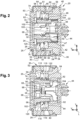
Fig.2 ] - lafigure 2 est une vue en coupe, par un plan longitudinal et vertical médian, du commutateur de lafigure 1 ; - [
Fig.3 ] - lafigure 3 est une est une vue en coupe, par un plan vertical et transversal médian, du commutateur de lafigure 1 ; - [
Fig.4 ] - lafigure 4 est une est une vue en perspective éclatée de l'embase inférieure, du ressort de rappel et de la tige supérieure d'actionnement du commutateur de lafigure 1 ; - [
Fig.5 ] - lafigure 5 est une vue en perspective de la tige supérieure d'actionnement du commutateur de lafigure 1 ; - [
Fig.6 ] - lafigure 6 est une vue en perspective de la tige supérieure d'actionnement et du ressort de rappel du commutateur de lafigure 1 ; [Fig.7 ] - lafigure 7 est une vue axiale en bout de la tige supérieure d'actionnement du commutateur de lafigure 1 ; - [
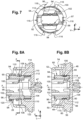
Fig.8A ] - lafigure 8A est une vue en coupe par un plan longitudinal et transversal médian de l'embase inférieure, du ressort de rappel et de la tige supérieure d'actionnement du commutateur de lafigure 1 avec la tige supérieure d'actionnement représentée en position haute de repos ; - [
Fig.8B ] - lafigure 8B est une vue analogue à celle de lafigure 8A sur laquelle la tige supérieure d'actionnement est représentée en position basse active, sans le ressort de rappel ; - [
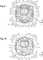
Fig.9 ] - lafigure 9 est une vue partielle en coupe par un plan longitudinal et transversal selon la ligne 9-9 de lafigure 8A ; - [
Fig.10 ] - lafigure 10 est une vue analogue à celle de lafigure 9 qui représente un second exemple de réalisation du ressort de rappel dont la spire d'extrémité inférieure est de forme circulaire.
- [
Fig.1 ] - therefigure 1 is an exploded side view of an embodiment of an electrical switch according to the invention; - [
Fig.2 ] - therepicture 2 is a sectional view, by a median longitudinal and vertical plane, of the switch of thefigure 1 ; - [
Fig.3 ] - therepicture 3 is a sectional view, by a median vertical and transverse plane, of the switch of thefigure 1 ; - [
Fig.4 ] - therefigure 4 is an exploded perspective view of the lower header, return spring, and upper switch actuating rod of thefigure 1 ; - [
Fig.5 ] - therefigure 5 is a perspective view of the upper switch actuating rod of thefigure 1 ; - [
Fig.6 ] - therefigure 6 is a perspective view of the upper actuating rod and switch return spring of thefigure 1 ; [Fig.7 ] - therefigure 7 is an axial end view of the upper switch actuating rod of thefigure 1 ; - [
Fig.8A ] - therefigure 8A is a cross-sectional view by a median longitudinal and transverse plane of the lower base, the return spring and the upper actuating rod of the switch of thefigure 1 with the upper actuating rod shown in the high rest position; - [
Fig.8B ] - therefigure 8B is a view analogous to that of thefigure 8A on which the upper actuating rod is shown in the active low position, without the return spring; - [
Fig.9 ] - therefigure 9 is a partial sectional view along a longitudinal and transverse plane along line 9-9 of thefigure 8A ; - [
Fig.10 ] - therefigure 10 is a view analogous to that of thefigure 9 which represents a second embodiment of the return spring whose lower end turn is circular.
Pour la description de l'invention et la compréhension des revendications, on adoptera à titre non limitatif et sans référence limitative à la gravité terrestre les orientations verticale, longitudinale et transversale selon le repère V, L, T indiqué aux figures dont les axes longitudinal L et transversal T s'étendent dans un plan horizontal.For the description of the invention and the understanding of the claims, the vertical, longitudinal and transverse orientations according to the reference V, L, T indicated in the figures whose longitudinal axes L and transverse T extend in a horizontal plane.
Par convention, l'axe vertical V est orienté du bas vers le haut.By convention, the vertical axis V is oriented from bottom to top.
Dans la description qui va suivre, des éléments identiques, similaires ou analogues seront désignés par les mêmes chiffres de référence.In the following description, identical, similar or analogous elements will be designated by the same reference numerals.
Dans l'exemple qui va suivre, le commutateur électrique 20 présente une symétrie générale de conception par rapport au plan vertical et longitudinal médian, et par rapport au plan vertical et transversal médian.In the example that follows, the
Verticalement de bas en haut, le commutateur électrique 20 - qui est notamment illustré notamment aux
L'embase inférieure 22, formant boîtier, est fermée à sa partie supérieure par un couvercle supérieur 26 d'actionnement qui est monté coulissant axialement par rapport à l'embase inférieure 22.The
Le commutateur électrique 20 comporte encore un ressort hélicoïdal de compression 28 qui est interposé axialement entre la tige supérieure d'actionnement 24 et l'embase inférieure 22, et une membrane latérale souple d'étanchéité 30 qui coopère avec le couvercle supérieur 26 et l'embase inférieure 22.The
Le commutateur électrique 20 comporte aussi deux lames de contact électrique 32 et 34 déformables élastiquement et dont chacune est reliée à une borne de raccordement 36. Ainsi, à titre non limitatif, le commutateur électrique 20 est ici du type normalement fermé dans lequel, en l'absence d'actionnement, les deux lames de contact électrique 32 et 34 sont en appui élastique mutuel et établissent la voix de commutation électrique entre deux bornes de raccordement 36 associées.The
À titre d'exemple non limitatif, le commutateur électrique 20 est du type lumineux et comporte à cet effet une source lumineuse 38 qui est par exemple une diode électroluminescente et qui est reliée à des bornes de raccordement 40 pour son alimentation.By way of non-limiting example, the
L'embase inférieure 22 est réalisée par surmoulage en matière plastique autour des éléments de raccordement électrique des lames de contact électrique 32 et 34 et de la source lumineuse 38.The
L'embase inférieure 22 se présente ici sous la forme d'un boîtier cylindrique d'axe A dont la face inférieure 42 comporte un pion 44 pour sa fixation sur un élément de support (non représentée) tel que par exemple une plaque à circuits imprimés.The
Le corps principal 46 de l'embase inférieure 22 délimite une cavité inférieure 48 ouverte verticalement vers le haut et une cavité supérieure 50 de forme générale cylindrique circulaire également ouverte vers le haut qui est délimitée par le bord supérieur 52 de l'embase inférieure 32.The
Les deux cavités 48 et 50 sont délimitées l'une par rapport à l'autre par une face radiale horizontale 49 qui est orientée verticalement vers le haut.The two
Les lames de contact électrique 32 et 34 s'étendent verticalement vers le haut à l'intérieur de l'embase inférieure 22 depuis le fond 47de la cavité inférieure 48. La source lumineuse 38 est également agencée dans le fond 47 de la cavité inférieure 48.The
La paroi latérale 54 de l'embase inférieure 22 de comporte une gorge radiale inférieure 56 dans laquelle est emboîtée élastiquement une nervure annulaire complémentaire 58 de la membrane d'étanchéité 30, et deux rainures axiales verticales et diamétralement opposées 60, fermées à leurs extrémités supérieures.The
Le couvercle supérieur d'actionnement 26 comporte une plaque supérieure horizontale 62 et une paroi latérale tubulaire cylindrique 64 qui comporte deux crochets diamétralement opposés 66 qui s'étend globalement vers l'intérieur et dont chacun est reçu dans une rainure associée 60 de la paroi latérale 54 de l'embase inférieure 22.The actuating
La plaque supérieure 62 est percée centralement et est ici fermée par une plaque translucide ou transparente 68 qui peut par exemple être colorée et/ou comporter un motif et qui peut permettre de visualiser l'allumage de la source lumineuse 38.The
La face inférieure interne 70 de la plaque supérieure 62 délimite un logement 72 ouvert axialement vers le bas et qui comporte un doigt radial d'indexation angulaire 74.The internal
La paroi latérale 63 de la plaque supérieure 62 comporte une gorge radiale interne 76 dans laquelle est emboîtée élastiquement un bourrelet annulaire complémentaire 78 de la membrane d'étanchéité 30.The
La cavité inférieure 48 de l'embase inférieure 22 comporte un alésage axial de guidage 80 qui se présente sous la forme d'une série de tronçons concaves qui, à titre non limitatif, sont ici au nombre de six.The
L'alésage axial de guidage 80 ainsi constitué s'étend verticalement vers le haut depuis le fond 47 et débouche axialement dans la face 49.The axial guide bore 80 thus formed extends vertically upwards from the bottom 47 and emerges axially in the
Conformément à l'invention, la cavité inférieure 48 de l'embase inférieure 22 comporte aussi une série de nervures axiales verticales 82 dont chacune s'étend radialement en saillie vers l'intérieur par rapport à la surface cylindrique concave de l'alésage de guidage 80.In accordance with the invention, the
À titre non limitatif, et comme on peut le voir notamment à la
Chaque nervure 82 est délimitée axialement vers le haut par une face supérieure radiale d'extrémité 84 qui est coplanaire à la face 49.Each
Ainsi, au sens de l'invention, les huit facettes 84 sont des facettes de butée constituant chacune une portion d'une face de butée horizontale est orientée verticalement vers le haut pour l'appui axial vers le bas du ressort de rappel 28.Thus, within the meaning of the invention, the eight
La cavité inférieure 48 de l'embase inférieure 22 comporte encore quatre dégagements 86 agencés angulairement à quatre-vingt-dix degrés d'angle.The
La tige supérieure d'actionnement 24 et une pièce moulée en matière plastique constituée essentiellement par un corps tubulaire creux 90 qui est délimité par une paroi cylindrique concave interne 92 et par une paroi latérale cylindrique convexe 94.The
A sa partie supérieure, le corps 90 se prolonge par une plaque radiale cylindrique supérieure 96 qui est reçue dans le logement 72 et qui comporte un cran d'indexation angulaire 97 dans lequel est reçu le doigt d'indexation 74 du couvercle d'actionnement 26.At its upper part, the
À l'intérieur du corps tubulaire 90, la tige supérieure d'actionnement 24 comporte deux plaques diamétrales 98 et 100 qui sont aptes à agir sur des éléments de contact électrique.Inside the
Dans l'exemple illustré aux figures, c'est la plaque diamétrale 98 qui est apte à coopérer avec les deux lames de contact électrique 32 et 34 pour les écarter longitudinalement l'une de l'autre afin d'interrompre la voie de commutation électrique à laquelle elles sont associées.In the example illustrated in the figures, it is the
Ainsi, en considérant la position de repos illustré à la
Un tel actionnement est effectué en agissant sur le couvercle supérieur d'actionnement 26 qui pousse axialement sur la plaque radiale supérieure 96 de la tige supérieure d'actionnement 24 pour déplacer cette dernière axialement vers le bas par rapport à l'embase inférieure 22 et donc par rapport aux éléments de contact électrique 32 et 34.Such actuation is performed by acting on the
La paroi latérale 94 de la tige supérieure d'actionnement 24 s'étend axialement depuis la face radiale annulaire inférieure 102 de la plaque radiale 96 jusqu'à la face radiale annulaire d'extrémité axiale inférieure 104.The
La paroi latérale 94 de la tige supérieure d'actionnement 24 comporte une gorge radiale interne 106 qui est délimitée par une paroi cylindrique convexe de fond 108.The
La gorge 106 est délimitée axialement vers le haut par un épaulement radial supérieur tronconique 110 dont le sommet est orienté vers le bas et qui constitue une rampe de raccordement entre la paroi 108 de fond de la gorge radiale 106 et la paroi latérale convexe 94 de la tige supérieure d'actionnement 24.The
La gorge 106 est délimitée axialement vers le haut par un épaulement radial inférieur 112 qui est délimité axialement par une face radiale 114 orientée axialement vers le haut.The
Conformément aux enseignements de l'invention, la paroi latérale 94 de la tige supérieure d'actionnement 24 comporte une série de rainures axiales verticales 116 dont chacune s'étend radialement vers l'intérieur par rapport à la surface de la paroi latérale cylindrique convexe 94.In accordance with the teachings of the invention, the
Le profil de la paroi de fond 118 de chaque rainure axiale 116 est ici commun au profil cylindrique convexe de la paroi de fond 108 de la gorge radiale 106. Chaque rainure axiale 116 débouche axialement vers le bas dans la face radiale annulaire d'extrémité axiale inférieure 104.The profile of the
Le nombre, les dimensions et la répartition angulaire des rainures axiales 116 est identique et complémentaire de ceux des nervures axiales 82 de l'embase inférieure 22.The number, dimensions and angular distribution of the
Ainsi, comme on peut le voir notamment à la
Le ressort de rappel 28 est ici un ressort hélicoïdal de compression, aussi appelé ressort à boudin, dont le corps cylindrique circulaire est traversé par la tige supérieure d'actionnement 24.The
La spire 120 d'extrémité supérieure est ici de forme globalement circulaire et elle est en appui axial contre la face radiale annulaire inférieure 102 de la plaque radiale 96.The
La spire 122 d'extrémité inférieure, aussi appelée dernière spire du ressort de rappel 28, est ici de forme globalement triangulaire et elle est en appui axial contre face radiale 114 orientée axialement vers le haut de l'épaulement radial inférieur 112.The
Ainsi, comme on peut le voir par exemple à la
Dans cet état initial du ressort de rappel 24, et comme on peut le voir aussi aux
Le diamètre interne moyen de la dernière spire est réduit par rapport au diamètre interne des autres spires de manière à être adjacente à la paroi latérale cylindrique convexe de la gorge radiale 106. Ainsi, la spire 122 est en appui axial sur les facettes 84 et la sensation tactile lors de l'actionnement est optimisée.The average internal diameter of the last turn is reduced compared to the internal diameter of the other turns so as to be adjacent to the convex cylindrical side wall of the
Dans la position haute de repos de la tige supérieure d'actionnement 24, la dernière spire 122 est en appui axial vers le bas contre la face radiale 49 de l'embase inférieure 22 et le ressort 24 exerce un effort de rappel élastique, vers le haut, de la tige supérieure d'actionnement 24, cette position haute de repos étant déterminée par l'appui axial vers le haut des crochets 66 contre le fond supérieur 61 des rainures axiales 60.In the high rest position of the
Comme on peut le voir en détail à la
Ainsi, lorsque le commutateur est actionné et que la tige supérieure d'actionnement 24 est enfoncée axialement vers le bas à l'encontre de l'effort de rappel élastique qui lui est appliqué par le ressort 28, la dernière spire 122 prend appui axialement sur les facettes 84 sans risque de coincement de cette spire 122 entre la tige supérieure d'actionnement 24 et l'embase inférieure 22, y compris lorsque la dernière spire 122 coopère avec le profil de came que constitue la rampe tronconique 110.Thus, when the switch is actuated and the
Dans le second exemple de réalisation représenté à la
Claims (6)
- Electrical switch (20) with axial actuation comprising:- a lower base (22);- an upper actuating rod (24) comprising a section whose cylindrical side wall (94) is guided axially sliding in a guide bore (80) formed in the lower base (22);- a elastic member (28) for returning the upper actuating rod (24) to a high rest position,wherein, under the action of an actuating force applied to the upper actuating rod (24) and against the force exerted by the elastic return member (28), the upper actuating rod (24) is displaced axially with respect to the lower base (22), along an actuating travel, towards an active lower position for changing the state of at least one electrical switching way (32, 34),and comprising an elastic ring (122):-- which is arranged in a peripheral housing (106) formed in said side wall (94)-- which is axially traversed by said section of the upper actuating rod (24)-- which, during the actuation travel of the upper actuation rod (24), is in axially downward abutment against a fixed stop surface belonging to the lower base (22);-- and which, during the actuation travel of the upper actuation rod (24), cooperates with a cam profile (110) formed in said side wall (94) which deforms it radially in order to produce an elastic resistance to the actuation of the upper actuation rod (24)characterised in that:- the guide bore (80) comprises a series of axial ribs (82) each of which projects radially inwardly of the guide bore (80) and is slidably received in a complementary axial groove (116) formed in said side wall (94); and- said fixed abutment surface is constituted by the radial upper end facets (84) of each axial rib (82).
- Switch according to the preceding claim, characterised in that said housing (106) is delimited axially downwards by a lower radial shoulder (112) and upwards by said cam profile (110).
- Switch according to the preceding claim, characterised in that said cam profile (110) is a cone section whose apex is oriented axially downwards forming a ramp with which the elastic ring (122) cooperates.
- A switch according to any one of claims 2 or 3, characterised in that each axial groove (116) formed in said side wall (94) extends axially upwardly beyond said cam profile (110).
- Electrical switch according to any one of the preceding claims, characterised in that the said elastic return member (28) is a helical compression spring through which the said section of the upper actuating rod (24) passes axially, the lower turn (122) of which constitutes the said elastic ring.
- An electrical switch according to the preceding claim taken in combination with any one of claims 2 to 4, characterised in that said spring (28) is mounted axially compressed between the upper radial end facets (84) of each axial rib (82) and an upper radial shoulder (102) which axially delimits said section upwards
Applications Claiming Priority (1)
| Application Number | Priority Date | Filing Date | Title |
|---|---|---|---|
| FR2103490A FR3121521B1 (en) | 2021-04-06 | 2021-04-06 | ELECTRIC SWITCH |
Publications (2)
| Publication Number | Publication Date |
|---|---|
| EP4071777A1 EP4071777A1 (en) | 2022-10-12 |
| EP4071777B1 true EP4071777B1 (en) | 2023-06-07 |
Family
ID=76730687
Family Applications (1)
| Application Number | Title | Priority Date | Filing Date |
|---|---|---|---|
| EP22161605.5A Active EP4071777B1 (en) | 2021-04-06 | 2022-03-11 | Electrical switch |
Country Status (5)
| Country | Link |
|---|---|
| US (1) | US11657991B2 (en) |
| EP (1) | EP4071777B1 (en) |
| JP (1) | JP7348342B2 (en) |
| CN (1) | CN115206715A (en) |
| FR (1) | FR3121521B1 (en) |
Family Cites Families (6)
| Publication number | Priority date | Publication date | Assignee | Title |
|---|---|---|---|---|
| FR2420834A1 (en) | 1978-03-24 | 1979-10-19 | Suisse Horlogerie | PUSHBUTTON SWITCH FOR WATCH PART |
| DE19607562C2 (en) * | 1996-02-29 | 1999-07-22 | Schneider Electric Gmbh | Switching device |
| JP4233174B2 (en) * | 1999-04-30 | 2009-03-04 | 富士通コンポーネント株式会社 | pointing device |
| JP6007498B2 (en) * | 2012-01-31 | 2016-10-12 | オムロン株式会社 | Operation switch |
| FR3066042A1 (en) * | 2017-05-02 | 2018-11-09 | Schneider Electric Industries Sas | EMERGENCY STOP DEVICE |
| US11469061B2 (en) * | 2020-02-26 | 2022-10-11 | GE Precision Healthcare LLC | Control device sensor rotation |
-
2021
- 2021-04-06 FR FR2103490A patent/FR3121521B1/en active Active
-
2022
- 2022-03-11 EP EP22161605.5A patent/EP4071777B1/en active Active
- 2022-03-28 JP JP2022051633A patent/JP7348342B2/en active Active
- 2022-04-01 CN CN202210347059.2A patent/CN115206715A/en active Pending
- 2022-04-06 US US17/658,145 patent/US11657991B2/en active Active
Also Published As
| Publication number | Publication date |
|---|---|
| FR3121521A1 (en) | 2022-10-07 |
| JP2022160372A (en) | 2022-10-19 |
| EP4071777A1 (en) | 2022-10-12 |
| CN115206715A (en) | 2022-10-18 |
| US11657991B2 (en) | 2023-05-23 |
| US20220319784A1 (en) | 2022-10-06 |
| JP7348342B2 (en) | 2023-09-20 |
| FR3121521B1 (en) | 2023-02-24 |
Similar Documents
| Publication | Publication Date | Title |
|---|---|---|
| EP2091836B1 (en) | Fluid product dispenser | |
| FR2961340A1 (en) | DOUBLE-ACTING TOUCH-EFFECT ELECTRIC SWITCH | |
| CA2342122C (en) | Spring-loaded push button | |
| FR2799570A1 (en) | PERFECTIONAL ELECTRICAL SWITCH WITH MULTI-CHANNEL TOUCH EFFECT AND SINGLE TRIGGER | |
| EP3399532B1 (en) | Emergency stop device | |
| EP1901327B1 (en) | Mechanism with two stable positions and electrical control device comprising same | |
| FR2844094A1 (en) | MULTIPLE SWITCHING DEVICE | |
| EP0871185B1 (en) | Push-button providing tactile and audible sign | |
| EP4071777B1 (en) | Electrical switch | |
| FR3060197A1 (en) | ELECTRIC SWITCH | |
| EP2978006B1 (en) | Electrical switch | |
| FR2796755A1 (en) | Electrical switch for use in mobile phone includes rotary coding wheel and axially movable switch to combine two switch actions in one switch | |
| FR3045927A1 (en) | "ELECTRICAL SWITCH WITH TOUCH-EFFECTIVE TOUCH RATE" | |
| FR2957187A1 (en) | DOUBLE-ACTING TOUCH-EFFECT ELECTRIC SWITCH | |
| EP1162521B1 (en) | Snap-action actuating device and watch provided with such a device | |
| WO2019129492A1 (en) | Device for controlling at least one electronic function of a portable object | |
| FR3108772A3 (en) | NORMALLY OPEN TYPE ELECTRIC SWITCH | |
| BE837174Q (en) | ELECTRICAL PUSH BUTTON SWITCH, INCLUDING ANGULAR MOBILE CREW BY BAGS UNDER THE ACTION OF THE PUSH BUTTON | |
| EP0130861B1 (en) | Tumbler switch | |
| EP4078641A1 (en) | Mechanism for an electrical switch, electrical assembly and electrical switch thereof | |
| EP0049180B1 (en) | One-piece distribution cap for a pressurized container, and its assembly | |
| FR3054370A1 (en) | ELECTRICAL SWITCH WITH MULTIPLE CHANNEL SWITCHES | |
| WO2023094760A1 (en) | Device for dispensing a fluid product | |
| FR2823729A1 (en) | Push button for a cosmetic spray actuates the spray head and is attached to arm pivoted on spray body, so that force is restored to required value if button is not pushed down vertically | |
| CH704691A1 (en) | Push button system for actuating functional actuating member placed inside case of e.g. electronic watch, has complementary guiding member connecting case and button head so as to partially resume operating efforts of system |
Legal Events
| Date | Code | Title | Description |
|---|---|---|---|
| PUAI | Public reference made under article 153(3) epc to a published international application that has entered the european phase |
Free format text: ORIGINAL CODE: 0009012 |
|
| STAA | Information on the status of an ep patent application or granted ep patent |
Free format text: STATUS: THE APPLICATION HAS BEEN PUBLISHED |
|
| AK | Designated contracting states |
Kind code of ref document: A1 Designated state(s): AL AT BE BG CH CY CZ DE DK EE ES FI FR GB GR HR HU IE IS IT LI LT LU LV MC MK MT NL NO PL PT RO RS SE SI SK SM TR |
|
| STAA | Information on the status of an ep patent application or granted ep patent |
Free format text: STATUS: REQUEST FOR EXAMINATION WAS MADE |
|
| 17P | Request for examination filed |
Effective date: 20221216 |
|
| RBV | Designated contracting states (corrected) |
Designated state(s): AL AT BE BG CH CY CZ DE DK EE ES FI FR GB GR HR HU IE IS IT LI LT LU LV MC MK MT NL NO PL PT RO RS SE SI SK SM TR |
|
| GRAP | Despatch of communication of intention to grant a patent |
Free format text: ORIGINAL CODE: EPIDOSNIGR1 |
|
| STAA | Information on the status of an ep patent application or granted ep patent |
Free format text: STATUS: GRANT OF PATENT IS INTENDED |
|
| RIC1 | Information provided on ipc code assigned before grant |
Ipc: H01H 13/14 20060101ALN20230213BHEP Ipc: H01H 13/02 20060101ALN20230213BHEP Ipc: H01H 13/85 20060101ALN20230213BHEP Ipc: H01H 13/52 20060101AFI20230213BHEP |
|
| GRAS | Grant fee paid |
Free format text: ORIGINAL CODE: EPIDOSNIGR3 |
|
| INTG | Intention to grant announced |
Effective date: 20230301 |
|
| GRAA | (expected) grant |
Free format text: ORIGINAL CODE: 0009210 |
|
| STAA | Information on the status of an ep patent application or granted ep patent |
Free format text: STATUS: THE PATENT HAS BEEN GRANTED |
|
| AK | Designated contracting states |
Kind code of ref document: B1 Designated state(s): AL AT BE BG CH CY CZ DE DK EE ES FI FR GB GR HR HU IE IS IT LI LT LU LV MC MK MT NL NO PL PT RO RS SE SI SK SM TR |
|
| REG | Reference to a national code |
Ref country code: GB Ref legal event code: FG4D Free format text: NOT ENGLISH |
|
| REG | Reference to a national code |
Ref country code: CH Ref legal event code: EP Ref country code: AT Ref legal event code: REF Ref document number: 1577495 Country of ref document: AT Kind code of ref document: T Effective date: 20230615 Ref country code: DE Ref legal event code: R096 Ref document number: 602022000114 Country of ref document: DE |
|
| P01 | Opt-out of the competence of the unified patent court (upc) registered |
Effective date: 20230713 |
|
| REG | Reference to a national code |
Ref country code: LT Ref legal event code: MG9D |
|
| REG | Reference to a national code |
Ref country code: NL Ref legal event code: MP Effective date: 20230607 |
|
| PG25 | Lapsed in a contracting state [announced via postgrant information from national office to epo] |
Ref country code: SE Free format text: LAPSE BECAUSE OF FAILURE TO SUBMIT A TRANSLATION OF THE DESCRIPTION OR TO PAY THE FEE WITHIN THE PRESCRIBED TIME-LIMIT Effective date: 20230607 Ref country code: NO Free format text: LAPSE BECAUSE OF FAILURE TO SUBMIT A TRANSLATION OF THE DESCRIPTION OR TO PAY THE FEE WITHIN THE PRESCRIBED TIME-LIMIT Effective date: 20230907 Ref country code: ES Free format text: LAPSE BECAUSE OF FAILURE TO SUBMIT A TRANSLATION OF THE DESCRIPTION OR TO PAY THE FEE WITHIN THE PRESCRIBED TIME-LIMIT Effective date: 20230607 |
|
| REG | Reference to a national code |
Ref country code: AT Ref legal event code: MK05 Ref document number: 1577495 Country of ref document: AT Kind code of ref document: T Effective date: 20230607 |
|
| PG25 | Lapsed in a contracting state [announced via postgrant information from national office to epo] |
Ref country code: RS Free format text: LAPSE BECAUSE OF FAILURE TO SUBMIT A TRANSLATION OF THE DESCRIPTION OR TO PAY THE FEE WITHIN THE PRESCRIBED TIME-LIMIT Effective date: 20230607 Ref country code: NL Free format text: LAPSE BECAUSE OF FAILURE TO SUBMIT A TRANSLATION OF THE DESCRIPTION OR TO PAY THE FEE WITHIN THE PRESCRIBED TIME-LIMIT Effective date: 20230607 Ref country code: LV Free format text: LAPSE BECAUSE OF FAILURE TO SUBMIT A TRANSLATION OF THE DESCRIPTION OR TO PAY THE FEE WITHIN THE PRESCRIBED TIME-LIMIT Effective date: 20230607 Ref country code: LT Free format text: LAPSE BECAUSE OF FAILURE TO SUBMIT A TRANSLATION OF THE DESCRIPTION OR TO PAY THE FEE WITHIN THE PRESCRIBED TIME-LIMIT Effective date: 20230607 Ref country code: HR Free format text: LAPSE BECAUSE OF FAILURE TO SUBMIT A TRANSLATION OF THE DESCRIPTION OR TO PAY THE FEE WITHIN THE PRESCRIBED TIME-LIMIT Effective date: 20230607 Ref country code: GR Free format text: LAPSE BECAUSE OF FAILURE TO SUBMIT A TRANSLATION OF THE DESCRIPTION OR TO PAY THE FEE WITHIN THE PRESCRIBED TIME-LIMIT Effective date: 20230908 |
|
| PG25 | Lapsed in a contracting state [announced via postgrant information from national office to epo] |
Ref country code: FI Free format text: LAPSE BECAUSE OF FAILURE TO SUBMIT A TRANSLATION OF THE DESCRIPTION OR TO PAY THE FEE WITHIN THE PRESCRIBED TIME-LIMIT Effective date: 20230607 |
|
| PG25 | Lapsed in a contracting state [announced via postgrant information from national office to epo] |
Ref country code: SK Free format text: LAPSE BECAUSE OF FAILURE TO SUBMIT A TRANSLATION OF THE DESCRIPTION OR TO PAY THE FEE WITHIN THE PRESCRIBED TIME-LIMIT Effective date: 20230607 |
|
| PG25 | Lapsed in a contracting state [announced via postgrant information from national office to epo] |
Ref country code: IS Free format text: LAPSE BECAUSE OF FAILURE TO SUBMIT A TRANSLATION OF THE DESCRIPTION OR TO PAY THE FEE WITHIN THE PRESCRIBED TIME-LIMIT Effective date: 20231007 |
|
| PG25 | Lapsed in a contracting state [announced via postgrant information from national office to epo] |
Ref country code: SM Free format text: LAPSE BECAUSE OF FAILURE TO SUBMIT A TRANSLATION OF THE DESCRIPTION OR TO PAY THE FEE WITHIN THE PRESCRIBED TIME-LIMIT Effective date: 20230607 Ref country code: SK Free format text: LAPSE BECAUSE OF FAILURE TO SUBMIT A TRANSLATION OF THE DESCRIPTION OR TO PAY THE FEE WITHIN THE PRESCRIBED TIME-LIMIT Effective date: 20230607 Ref country code: RO Free format text: LAPSE BECAUSE OF FAILURE TO SUBMIT A TRANSLATION OF THE DESCRIPTION OR TO PAY THE FEE WITHIN THE PRESCRIBED TIME-LIMIT Effective date: 20230607 Ref country code: PT Free format text: LAPSE BECAUSE OF FAILURE TO SUBMIT A TRANSLATION OF THE DESCRIPTION OR TO PAY THE FEE WITHIN THE PRESCRIBED TIME-LIMIT Effective date: 20231009 Ref country code: IS Free format text: LAPSE BECAUSE OF FAILURE TO SUBMIT A TRANSLATION OF THE DESCRIPTION OR TO PAY THE FEE WITHIN THE PRESCRIBED TIME-LIMIT Effective date: 20231007 Ref country code: EE Free format text: LAPSE BECAUSE OF FAILURE TO SUBMIT A TRANSLATION OF THE DESCRIPTION OR TO PAY THE FEE WITHIN THE PRESCRIBED TIME-LIMIT Effective date: 20230607 Ref country code: CZ Free format text: LAPSE BECAUSE OF FAILURE TO SUBMIT A TRANSLATION OF THE DESCRIPTION OR TO PAY THE FEE WITHIN THE PRESCRIBED TIME-LIMIT Effective date: 20230607 Ref country code: AT Free format text: LAPSE BECAUSE OF FAILURE TO SUBMIT A TRANSLATION OF THE DESCRIPTION OR TO PAY THE FEE WITHIN THE PRESCRIBED TIME-LIMIT Effective date: 20230607 |
|
| PG25 | Lapsed in a contracting state [announced via postgrant information from national office to epo] |
Ref country code: PL Free format text: LAPSE BECAUSE OF FAILURE TO SUBMIT A TRANSLATION OF THE DESCRIPTION OR TO PAY THE FEE WITHIN THE PRESCRIBED TIME-LIMIT Effective date: 20230607 |
|
| REG | Reference to a national code |
Ref country code: DE Ref legal event code: R097 Ref document number: 602022000114 Country of ref document: DE |
|
| PLBE | No opposition filed within time limit |
Free format text: ORIGINAL CODE: 0009261 |
|
| STAA | Information on the status of an ep patent application or granted ep patent |
Free format text: STATUS: NO OPPOSITION FILED WITHIN TIME LIMIT |
|
| PG25 | Lapsed in a contracting state [announced via postgrant information from national office to epo] |
Ref country code: DK Free format text: LAPSE BECAUSE OF FAILURE TO SUBMIT A TRANSLATION OF THE DESCRIPTION OR TO PAY THE FEE WITHIN THE PRESCRIBED TIME-LIMIT Effective date: 20230607 |
|
| PGFP | Annual fee paid to national office [announced via postgrant information from national office to epo] |
Ref country code: DE Payment date: 20231229 Year of fee payment: 3 |
|
| PG25 | Lapsed in a contracting state [announced via postgrant information from national office to epo] |
Ref country code: SI Free format text: LAPSE BECAUSE OF FAILURE TO SUBMIT A TRANSLATION OF THE DESCRIPTION OR TO PAY THE FEE WITHIN THE PRESCRIBED TIME-LIMIT Effective date: 20230607 |