EP4071069A1 - Starre verpackung für stabförmige artikel, insbesondere rauchartikel, und verfahren zur herstellung - Google Patents
Starre verpackung für stabförmige artikel, insbesondere rauchartikel, und verfahren zur herstellung Download PDFInfo
- Publication number
- EP4071069A1 EP4071069A1 EP22167217.3A EP22167217A EP4071069A1 EP 4071069 A1 EP4071069 A1 EP 4071069A1 EP 22167217 A EP22167217 A EP 22167217A EP 4071069 A1 EP4071069 A1 EP 4071069A1
- Authority
- EP
- European Patent Office
- Prior art keywords
- wall
- container
- articulated parallelogram
- article
- support system
- Prior art date
- Legal status (The legal status is an assumption and is not a legal conclusion. Google has not performed a legal analysis and makes no representation as to the accuracy of the status listed.)
- Pending
Links
Images











Classifications
-
- A—HUMAN NECESSITIES
- A24—TOBACCO; CIGARS; CIGARETTES; SIMULATED SMOKING DEVICES; SMOKERS' REQUISITES
- A24F—SMOKERS' REQUISITES; MATCH BOXES; SIMULATED SMOKING DEVICES
- A24F15/00—Receptacles or boxes specially adapted for cigars, cigarettes, simulated smoking devices or cigarettes therefor
- A24F15/01—Receptacles or boxes specially adapted for cigars, cigarettes, simulated smoking devices or cigarettes therefor specially adapted for simulated smoking devices or cigarettes therefor
-
- B—PERFORMING OPERATIONS; TRANSPORTING
- B65—CONVEYING; PACKING; STORING; HANDLING THIN OR FILAMENTARY MATERIAL
- B65D—CONTAINERS FOR STORAGE OR TRANSPORT OF ARTICLES OR MATERIALS, e.g. BAGS, BARRELS, BOTTLES, BOXES, CANS, CARTONS, CRATES, DRUMS, JARS, TANKS, HOPPERS, FORWARDING CONTAINERS; ACCESSORIES, CLOSURES, OR FITTINGS THEREFOR; PACKAGING ELEMENTS; PACKAGES
- B65D85/00—Containers, packaging elements or packages, specially adapted for particular articles or materials
- B65D85/07—Containers, packaging elements or packages, specially adapted for particular articles or materials for compressible or flexible articles
- B65D85/08—Containers, packaging elements or packages, specially adapted for particular articles or materials for compressible or flexible articles rod-shaped or tubular
- B65D85/10—Containers, packaging elements or packages, specially adapted for particular articles or materials for compressible or flexible articles rod-shaped or tubular for cigarettes
-
- A—HUMAN NECESSITIES
- A24—TOBACCO; CIGARS; CIGARETTES; SIMULATED SMOKING DEVICES; SMOKERS' REQUISITES
- A24F—SMOKERS' REQUISITES; MATCH BOXES; SIMULATED SMOKING DEVICES
- A24F15/00—Receptacles or boxes specially adapted for cigars, cigarettes, simulated smoking devices or cigarettes therefor
- A24F15/20—Receptacles or boxes specially adapted for cigars, cigarettes, simulated smoking devices or cigarettes therefor with separate compartments for each cigar or cigarette
-
- B—PERFORMING OPERATIONS; TRANSPORTING
- B65—CONVEYING; PACKING; STORING; HANDLING THIN OR FILAMENTARY MATERIAL
- B65D—CONTAINERS FOR STORAGE OR TRANSPORT OF ARTICLES OR MATERIALS, e.g. BAGS, BARRELS, BOTTLES, BOXES, CANS, CARTONS, CRATES, DRUMS, JARS, TANKS, HOPPERS, FORWARDING CONTAINERS; ACCESSORIES, CLOSURES, OR FITTINGS THEREFOR; PACKAGING ELEMENTS; PACKAGES
- B65D5/00—Rigid or semi-rigid containers of polygonal cross-section, e.g. boxes, cartons or trays, formed by folding or erecting one or more blanks made of paper
- B65D5/42—Details of containers or of foldable or erectable container blanks
- B65D5/44—Integral, inserted or attached portions forming internal or external fittings
- B65D5/50—Internal supporting or protecting elements for contents
- B65D5/5002—Integral elements for containers having tubular body walls
- B65D5/5016—Integral elements for containers having tubular body walls formed by folding inwardly of extensions hinged to the side edges of the body
Definitions
- the present invention relates to a rigid pack for rod-shaped articles, in particular smoking articles and a relative manufacturing method.
- a rigid packet of cigarettes comprises a group of cigarettes in direct contact with each other (and normally arranged on three layers consisting of seven, six and seven cigarettes, respectively), a wrapper which completely wraps the group of cigarettes, and a container that is provided with a hinged lid and houses the wrapper in its inside which envelops the group of cigarettes.
- the extraction of the first cigarette is relatively easy (despite the fact that the cigarettes are in close contact with each other and also slightly pressed the ones against the others) because the cigarettes can be easily and widely elastically deformed and therefore it is possible to "create" space with the fingers in order to extract (pull out) the first cigarette from the group of cigarettes.
- a traditional pack of this type is not suitable for containing rigid (i.e. non-deformable) cartridges for new generation cigarettes (e.g. electronic cigarettes), because since the rigid cartridges cannot be elastically deformed (e.g. because they are enclosed in a cylinder casing made of plastic or metallic material), it becomes extremely difficult (if not impossible) to extract the first rigid cartridge without damage.
- a rigid pack of this type comprises a group of smoking articles, a container that is provided with a hinged lid and houses the group of smoking articles in its inside, and a support system that is arranged inside the container and defines a series of seats each adapted to contain a single smoking article while keeping the smoking article separate and at a certain distance from the adjacent smoking articles. This makes it easy to grasp each smoking article (as it is spaced apart from the adjacent smoking articles) in order to extract the smoking article from the pack.
- the support system comprises at least one wall that is arranged parallel to a back wall of the container, is arranged perpendicular to the smoking articles (i.e., to the longitudinal axis of the smoking articles), and has a plurality of through holes each of which is engaged by a corresponding smoking article in order to define a certain and predetermined position of the smoking article.
- rigid packs of smoking articles of this type are complex (and therefore expensive) to produce as they require the presence of: a first bending unit for making, by bending a first blank, the support system and for coupling the group of smoking articles to the support system, a second bending unit for making, by bending a second blank, the container around the support system coupled to the group of smoking articles, and a transport unit for transferring the support system coupled to the group of smoking articles from the first bending unit to the second bending unit.
- these three units (which are distinct from each other and use two different blanks) form a particularly complex, costly and cumbersome packing system.
- Patent application JPH1135081A describes a box for medicine bottles having a high containment to prevent the bottles from being damaged by hitting each other during transport.
- Patent application WO2007091116A1 describes a blank for packing vials (or similar elongated articles) and comprising a plurality of adjacent blank sections that can be bent to provide a box having an inner support portion for housing and holding the vials in corresponding holding holes.
- Patent application BE639781A describes a containing element for a rigid pack for rod-shaped articles.
- Aim of the present invention is to provide a rigid pack for rod-shaped articles, in particular smoking articles and a relative manufacturing method, which rigid pack is free of the disadvantages described above and is therefore easy and inexpensive to produce (i.e. requires a single simple and compact packer machine for its production).
- the number 1 denotes a rigid pack for smoking articles as a whole.
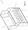
- the pack 1 comprises a parallelepiped-shaped container 2 which is made of cardboard or rigid paperboard and is provided with a boxed lid 3 and hinged along a hinge 4 (shown in Figure 2 ) to rotate between an open position (shown in Figure 3 ) and a closed position (shown in Figures 1 and 2 ).
- the container 2 has a substantially rectangular parallelepiped shape and has an upper wall 5 (completely belonging to the lid 3), a lower wall 6 opposite to the upper wall 5, a front wall 7 (partly belonging to the lid 3) and a rear wall 8 (partly belonging to the lid 3 and in which the hinge 4 is obtained) which are parallel and opposite to each other, and two side walls 9 and 10 (partly belonging to the lid 3) which are parallel and opposite to each other.
- the container 2 has a substantially rectangular parallelepiped shape and has an upper wall 5 (completely belonging to the lid 3), a lower wall 6 opposite to the upper wall 5, a front wall 7 (partly belonging to the lid 3) and a rear wall 8 (partly belonging to the lid 3 and in which the hinge 4 is obtained) which are parallel and opposite to each other, and two side walls 9 and 10 (partly belonging to the lid 3) which are parallel and opposite to each other.
- the pack 1 further comprises a rigid collar 11, which is connected (by gluing) bent in a "U" shape inside the container 2 in order to partially project outside of an open upper end of the container 2 and engage a corresponding inner surface of the lid 3, when the lid 3 is arranged in the closed position.
- the collar 11 comprises a front wall 12 which is glued (obviously below the lid 3) to the front wall 7 of the container 2 and two side walls 13 which are glued (obviously below the lid 3) to the side walls 9 and 10 of the container 2.
- the pack 1 comprises a group of rod-shaped smoking articles 14 (e.g. rigid cartridges for electronic cigarettes), each of which is shaped like an elongated cylinder (i.e. having a cross-sectional diameter much smaller than a longitudinal extension).
- the group consists of twenty smoking articles 14 which are arranged on three layers composed of seven, six and seven smoking articles 14, respectively.
- the pack 1 comprises a support system 15 that is arranged inside the container 2 and defines a series of seats each adapted to contain a single smoking article 14 while keeping the smoking article 14 separate and at a certain distance from the adjacent smoking articles 14.
- the support system 15 comprises two containing walls 16 and 17 which are arranged at a certain distance from each other parallel to the upper wall 5 and to the lower wall 6 of the container 2, are arranged perpendicular to the smoking articles 14 (i.e. to the longitudinal axis of the smoking articles 14), and have a plurality of through holes 18 each of which is engaged by a corresponding smoking article 14 in order to define a certain and predetermined position of the smoking article 14.
- the set of two holes 18 aligned with each other defines a seat for a corresponding smoking article 14; that is, a smoking article 14 engaging two holes 18 aligned with each other of the two containing walls 16 and 17 is in a predetermined and stable position within the container 2.
- the containing wall 16 is connected at one end and along a pre-weakened transverse bending line 19 (better shown in Figure 7 ) to a support tab 20 which is bent by 90° relative to the connection wall 16 and directly (i.e. with direct contact) rests against the front wall 12 of the collar 11 which in turn directly rests against the front wall 7 of the container 2; furthermore, the containing wall 16 is connected at an opposite end (relative to the support tab 20) and along a pre-weakened transverse bending line 19 (better shown in Figure 7 ) to a support tab 21 which is bent by 90° relative to the connection wall 16 and directly (i.e. with direct contact) rests against the rear wall 8 of the container 2.
- the support tabs 20 and 21 are parallel to and facing each other.
- the containing wall 17 is connected at one end and along a pre-weakened transverse bending line 19 (best shown in Figure 7 ) to a support tab 22 which is bent by 90° relative to the connection wall 17 and rests against the front wall 12 of the collar 11 (which in turn directly rests against the front wall 7 of the container 2) with the interposition of the support tab 20 (i.e.
- the containing wall 17 is connected at an opposite end (relative to the support tab 22) and along a pre-weakened transverse bending 19 (better shown in Figure 7 ) to a support tab 23 which is bent by 90° relative to the connection wall 16 and rests against the rear wall 8 of the container 2 with the interposition of the support tab 21 (i.e. it rests against the support tab 21 which in turn directly rests against the rear wall 8 of the container 2).
- the support tabs 22 and 23 are parallel to and facing each other.
- the support tab 21 rests against and is glued to the rear wall 8 of the container 2
- the support tab 22 rests against and is glued to the support tab 20
- the support tab 23 rests against and is glued to the support tab 21;
- the support tab 20 only rests against, but not glued to, the front wall 12 of the collar 11 (which in turn rests against and is glued to the front wall 7 of the container 2) to allow the support tab 20 to be separated from the front wall 12 of the collar 11 (a feature that will be used during the manufacture of the rigid pack 1 as will be described below).
- the support system 15 comprises a connection wall 24 which is parallel to the containing walls 16 and 17 (and therefore also to the lower wall 6 of the container 2 and to the upper wall 5 of the container 2) and connects the support tabs 21 and 22 to each other; the connection wall 24 is arranged below both containing walls 16 and 17, i.e. starting from the top (the upper wall 5) and going downwards (the lower wall 6) they are provided in succession as follows: the containing wall 16, the containing wall 17 and the connection wall 24.
- the connection wall 24 is connected at one end and along a pre-weakened transverse bending line 19 (best shown in Figure 7 ) to the support tab 21 and is connected at the opposite end and along a pre-weakened transverse bending line 19 (best shown in Figure 7 ) to the support tab 22.
- the support tabs 21 and 22 (which are parallel to and facing each other) are bent by 90° relative to the connection wall 24.
- the support tab 20 is connected along a pre-weakened transverse bending line 19 (better shown in Figure 7 ) to the lower wall 6 of the container 2 (in particular to a panel 6' which constitutes an inner part of the lower wall 6 of the container 2) and is bent by 90° relative to the lower wall 6 of the container 2 (in particular relative to the panel 6' which constitutes an inner part of the lower wall 6 of the container 2).
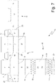
- the container 2, the collar 11 and the support system 15 are manufactured using a single blank 25 comprising: a panel 5' which constitutes an inner part of the upper wall 5 of the container 2, the rear wall 8 of the container 2 which is connected to the panel 5' along a pre-weakened transverse bending line 19, a panel 6' which constitutes an inner part of the lower wall 6 of the container 2 and is connected to the rear wall 8 along a pre-weakened transverse bending line 19, the support tab 20 connected to the panel 6' along a pre-weakened transverse bending line 19, the containing wall 16 connected to the support tab 20 along a pre-weakened transverse bending line 19, the support tab 21 connected to the containing wall 16 along a pre-weakened transverse bending line 19, the connection wall 24 connected to the support tab 21 along a pre-weakened transverse bending line 19, the support tab 22 connected to the connection wall 24 along a pre-weakened transverse bending line 19, the containing wall 17 connected to the support tab 22 along a pre-weakened transverse bending line 19,
- the blank 25 comprises a panel 9' which is arranged on one side of the rear wall 8, is connected to the rear wall 8 along a pre-weakened longitudinal bending line 26, and constitutes an outer part of the side wall 9; further, the blank 25 comprises the other side wall 10 which is arranged on a side of the rear wall 8 opposite to the panel 9' and is connected to the rear wall 8 along a pre-weakened longitudinal bending line 26.
- the blank 25 comprises: the front wall 7 which is connected to the side wall 10 along a pre-weakened longitudinal bending line 26, a panel 9" which is connected to the front wall 7 from the opposite side of the side wall 10 and along a pre-weakened longitudinal bending line 26 and constitutes an inner part of the side wall 9 by being overlapped and glued to the panel 9', a side wall 13 of the collar 11 which is connected to the panel 9" along a pre-weakened longitudinal bending line 26, the front wall 12 of the collar 11 which is connected to the side wall 13 along a pre-weakened longitudinal bending line 26, and the other side wall 13 of the collar 11 which is connected to the front wall 12 along a pre-weakened longitudinal bending line 26.
- the blank 25 comprises a panel 5" which constitutes an outer part of the upper wall 5 of the container 2 being overlapped and glued to the panel 5' and connected to the front wall 7 of the container 2 along a pre-weakened transverse bending line 19, and a panel 6" which constitutes an outer part of the lower wall 6 of the container 2 being overlapped and glued to the panel 6' and which is connected to the front wall 7 of the container 2 along a pre-weakened transverse bending line 19.
- the front wall 7 and the side walls 9 and 10 are crossed by a pre-weakened separation line 27 which connects to the hinge 4 of the lid 3 and separates the portions belonging to the lid 3 from the remaining portions not belonging to the lid 3; after the first opening of the rigid pack 1, the pre-weakened separation line 27 is definitively broken to allow the lid 3 to be separated from the rest of the container 2 by rotating around the hinge 4.
- Figure 8 shows a variant of the rigid pack 1: the rigid pack 1 shown in Figure 8 differs from the rigid pack 1 shown in Figures 1-6 in its proportions (in particular, the rigid pack 1 shown in Figure 8 is narrower and wider than the rigid pack 1 shown in Figures 1-6 ) and in the arrangement of the smoking articles 14 (in the rigid pack 1 shown in Figure 8 , the group of smoking articles 14 consists of twenty smoking articles 14 which are arranged on two layers consisting of ten smoking articles 14, respectively).
- Figure 9 shows the blank 25 being used to manufacture the rigid pack 1 shown in Figure 8 .
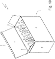
- Figure 10 shows another variant of the rigid pack 1: the rigid pack 1 shown in Figure 10 differs from the rigid pack 1 shown in Figures 1-6 in the conformation of the lid 3: in the rigid pack 1 shown in Figure 10 , the lid 3 is not boxed but is substantially composed only of the upper wall 5 and consequently there is no collar 11 (whose function, i.e. keeping the lid 3 in the closed position, is performed by a tab that protrudes from the upper wall 5 and is wedged between the upper wall 5 and the front wall 7).
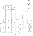
- Figure 11 shows the blank 25 being used to manufacture the rigid pack 1 shown in Figure 10 .
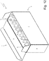
- Figure 12 shows a variant of the rigid pack 1: the rigid pack 1 shown in Figure 12 differs from the rigid pack 1 shown in Figure 10 in its proportions (in particular, the rigid pack 1 shown in Figure 12 is narrower and wider than the rigid pack 1 shown in Figure 10 ) and in the arrangement of the smoking articles 14 (in the rigid pack 1 shown in Figure 12 , the group of smoking articles 14 consists of twenty smoking articles 14 which are arranged on two layers consisting of ten smoking articles 14, respectively).
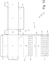
- Figure 13 shows the blank 25 being used to manufacture the rigid pack 1 shown in Figure 12 .
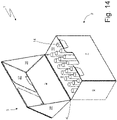
- FIG 14 shows another variant of the rigid pack 1: the rigid pack 1 shown in Figure 14 differs from the rigid pack 1 shown in Figures 1-6 in the conformation of the lid 3: in the rigid pack 1 shown in Figure 14 the lid 3 is boxed but instead of being an integral part of the container 2 it is an outer element relative to the container 2, it embraces the container 2 from the outside and has its own front wall 27 and its own side walls 28 which are independent of and completely separate from the respective walls 7, 9 and 10 of the container 2. Furthermore, in the rigid pack 1 shown in Figure 14 there is no collar 11 whose function is completely unnecessary given the different conformation of the lid 3.
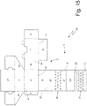
- Figure 15 shows the blank 25 being used to manufacture the rigid pack 1 shown in Figure 14 .
- Figure 16 shows a variant of the rigid pack 1: the rigid pack 1 shown in Figure 16 differs from the rigid pack 1 shown in Figure 14 in its proportions (in particular, the rigid pack 1 shown in Figure 16 is narrower and wider than the rigid pack 1 shown in Figure 14 ) and in the arrangement of the smoking articles 14 (in the rigid pack 1 shown in Figure 16 , the group of smoking articles 14 consists of twenty smoking articles 14 which are arranged on two layers consisting of ten smoking articles 14, respectively).
- Figure 17 shows the blank 25 being used to manufacture the rigid pack 1 shown in Figure 16 .
- the container 2 is slidably inserted inside a further, more external container and must be extracted by axial sliding in order to access the smoking articles 14; in this further embodiment, the container 2 may be provided with a lid 3 (and thus with an upper wall 5) or may also be without a lid 3 (and thus with an upper wall 5).
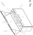
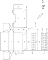
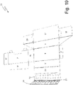
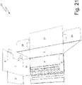
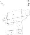
- the blank 25 is bent on itself in order to assume a partially bent but still flat shape (i.e. without delimiting a containment volume in its inside) shown in its final form in Figure 22 .
- the support tab 22 is bent by 180° around the corresponding transverse bending line 19 and relative to the connection wall 24 until the containing wall 17 rests partially above the connection wall 24 and partially above the support tab 21 and especially until the support tab 23 rests above the support tab 21.
- the support tab 23 is glued to the support tab 21 establishing a permanent and non-separable union with the support tab 21 due to a glue previously applied on the support tab 23 or on the support tab 21.
- the support tab 21 is bent by 180° around the corresponding transverse bending line 19 and relative to the containing wall 16 until the support tab 22 rests above the support tab 20.
- the support tab 22 is glued to the support tab 20 establishing a permanent and non-separable union with the support tab 20 due to a glue previously applied on the support tab 22 or on the support tab 20.
- the support tab 20 is bent by 180° around the corresponding transverse bending line 19 and relative to the panel 6' until the support tab 21 rests above the rear wall 8.
- the support tab 21 is glued to the rear wall 8 establishing a permanent and non-separable union with the rear wall 8 due to a glue previously applied on the support tab 21 or on the rear wall 8.
- the panel 9' is bent by 180° around the corresponding longitudinal bending line 26 and relative to the rear wall 8 in order to rest the panel 9' against the rear wall 8 and subsequently (or simultaneously) the front wall 7 is bent by 180° around the corresponding longitudinal bending line 26 and relative to the side wall 10 in order to overlap the front wall 7 partially on the side wall 9 and partially on the rear wall 8 and especially to overlap the panel 9" on the previously bent panel 9'.
- the panel 9' is glued to the panel 9" establishing a permanent and non-separable union with the panel 9" due to a glue previously applied on the panel 9" or on the panel 9'.
- the blank 25 has the appearance shown in Figure 22 and has a partially bent but still flat shape (i.e. without delimiting a containment volume in its inside); preferably, all the above-described bending and gluing operations are carried out at the premises of the supplier producing the blank 25 and the partially bent blank 25 (as shown in Figure 22 ) is fed to a packer machine which, starting from the partially bent blank 25, manufactures the rigid pack 1 in the manner described below.
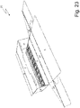
- the packer machine (normally by pushing on the side wall 10) bends by 90° both side walls 9 and 10 of the container 2 relative to the rear wall 8 of the container 2 an equivalent and simultaneous bending of both side walls 9 and 10 of the container 2 also relative to the front wall 7 of the container 2.
- the packer machine (normally by pushing on the panel 6') bends the panel 6' by 90° around the corresponding transverse bending line 19 and relative to the rear wall 8 consequently the lifting of the entire support system 15, i.e.: the 90° bending of the connection wall 24 around the corresponding transverse bending line 19 and relative to the support tab 21, the 90° bending of the containing wall 17 around the corresponding transverse bending line 19 and relative to the support tab 23, and the 90° bending of the containing wall 16 around the corresponding transverse bending line 19 and relative to the support tab 21.
- the thrust that is exerted on the panel 6' and which leads to the 90° bending of the panel 6' is also transmitted through the support tab 20 to the walls 16, 17 and 24, which are also bent by 90° in a synchronised manner with the panel 6'.
- the packer machine (pushing on the panel 6") bends the panel 6" by 90° around the corresponding transverse bending line 19 and relative to the front wall 7 of the container 2 until the panel 6" overlaps the panel 6'.
- the panel 6' is glued to the panel 6" establishing a permanent and non-separable union with the panel 6" due to a glue previously applied on the panel 6" or on the panel 6'; the permanent union between the two panels 6' and 6" stabilises (i.e. "freezes") the conformation of the support system 15 which loses all freedom of movement.
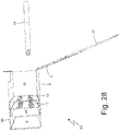
- the packer machine bends the upper wall 5 in order to move the upper wall 5 away from the opening upper end of the container 2 so as to facilitate the entry of the smoking articles 14; this step is obviously optional, but is preferably performed in order to have a "free field" for the introduction of the smoking articles 14 into the container 2.
- the smoking articles 14 are inserted into the container 2 by feeding one layer of smoking articles 14 at a time so that each smoking article 14 is arranged in a corresponding seat of the support system 15, i.e. each smoking article 14 enters two respective holes 18 of the two containing walls 16 and 17.
- the support system 15 consists of a first articulated parallelogram comprising a frame (the support tab 21) which is glued to the rear wall 8 of the container 2, four cranks (the panel 6", the connection wall 24, and the two support walls 16 and 17), and a connecting rod (the support tab 20) which only rests against the front wall 7 of the container 2; so that, while the rigid pack 1 is being manufactured, the support system 15 can be formed with the first articulated parallelogram in a flat condition and can subsequently be expanded by opening the first articulated parallelogram by means of a rotation of both cranks.
- the rear wall 8 of the container 2, the front wall 7 of the container 2, and the two side walls 9 and 10 of the container 2 constitute a second articulated parallelogram so that, while the rigid pack 1 is being manufactured, the second articulated parallelogram can be formed in a flat condition and can subsequently be expanded by opening the second articulated parallelogram by means of a rotation of both side walls 9 and 10 of the container 2 constituting the cranks of the second articulated parallelogram (instead, the rear wall 8 of the container 2 constitutes the frame of the second articulated parallelogram and the front wall 7 of the container 2 constitutes the connecting rod of the second articulated parallelogram).
- the manufacture of the rigid pack 1 envisages, at the premises of the supplier manufacturing the blank 15, forming the support system 15 with the first articulated parallelogram in a flat condition and forming the second articulated parallelogram in a flat condition; subsequently, the packer machine (which receives the blanks 25 with the articulated parallelograms already formed and in a flat condition) expands (i.e. "unwinds” ) the second articulated parallelogram, subsequently it expands (i.e.
- the frame of the first articulated parallelogram consists of the support tab 20 which is glued (directly or indirectly) to the front wall 7 of the container 2 while the connecting rod of the first articulated parallelogram consists of the support tab 21 which only rests against the rear wall 8 of the container 2.
- the collar 11 is preliminarily bent and glued against the side wall 10 of the container 2, against the front wall 7 of the container 2, and against the panel 9" of the container 2; in other words, the side wall 13 of the collar 11 is preliminarily bent by 180°, around the corresponding longitudinal bending line 26 and relative to the panel 9" so as to overlap and glue the side wall 13 of the collar 11 to the panel 9" of the container 2, to overlap and glue the front wall 12 of the collar 11 to the front wall 7 of the container 2, and to overlap and glue the other side wall 13 of the collar 11 to the side wall 10 of the container 2.
- the bending of the blanks 25 shown in Figures 7 and 9 is entirely analogous to the bending of the blanks 25 shown in Figures 11 , 13 , 15 and 17 .
- the holes 18 of the containing walls 16 and 17 may have an edge that is smaller than a smoking article 14 (i.e. that has a smaller inner diameter than an outer diameter of a smoking article 14) and can be deformed so as to hold, through interference, a corresponding smoking article 14; in this way, when a smoking article 14 enters a hole 18 it must deform (more or less elastically) the edge of the hole 18 and two important results are obtained: the hole 18 is self-centring (i.e.
- the edge of the hole 18 tends to centre the smoking article 14 by bringing it into the desired centred position), and the hole 18 holds with a certain (elastic) force the smoking article 14 further stabilising the position of the smoking article 14.
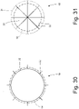
- the edge of a hole 18 is made deformable (more or less elastically) by making cuts (at least three, but generally not less than four), which are oriented more or less radially and originate from the edge of the hole 18.
- each hole 18 consists of a circular through incision 29 (which creates an actual hole with no material on its inside) having a smaller inner diameter than an outer diameter of a smoking article 14 and a series of cuts 30 which are oriented radially and originate from the incision 29.
- each hole 18 comprises a series of cuts 31 originating from an outer (virtual) circular ring 32 and joining at the centre of the ring 32 in order to define a plurality of flexible flaps 33; according to one possible embodiment, the ring 32 is pre-weakened to increase the flexibility of the flaps 33. In addition, the ring 32 has a greater diameter than an outer diameter of a smoking article 14.
- the holes 18 have a circular shape, i.e. a perfectly circular symmetry around a centre.
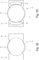
- the holes 18 have a central part 34 with a circular shape which is suited to hold, through interference, a corresponding smoking article 14 and two side appendages 35 which are not suited to hold a corresponding smoking article 14 but are suited to allow for the passage of two accompanying elements 36 (shown in Figure 33 ) which accompany the insertion movement of the corresponding smoking article 14 into the hole 18.
- the support system 15 comprises a single containing wall 16 or the support system 15 comprises three or more containing walls 16 and 17.
- the above described pack 1 has several advantages.
- the rigid pack 1 described above requires the use of a single blank 25 to manufacture all components (i.e. the container 2, the collar 11, and the support system 15) and this allows the rigid pack 1 to be manufactured using a single wrapping unit. Consequently, the rigid pack 1 described above is simple and inexpensive to produce.
- the rigid pack 1 described above provides a protected and secure housing for smoking articles 14 while allowing a very easy picking of the smoking articles 14 thanks to the distance that is maintained inside the container 2 between a smoking article 14 and the adjacent smoking articles 14.
Landscapes
- Engineering & Computer Science (AREA)
- Mechanical Engineering (AREA)
- Packaging Of Annular Or Rod-Shaped Articles, Wearing Apparel, Cassettes, Or The Like (AREA)
- Glass Compositions (AREA)
- Cigarettes, Filters, And Manufacturing Of Filters (AREA)
- Cartons (AREA)
Applications Claiming Priority (1)
| Application Number | Priority Date | Filing Date | Title |
|---|---|---|---|
| IT102021000008867A IT202100008867A1 (it) | 2021-04-09 | 2021-04-09 | Pacchetto rigido di articoli, in particolare da fumo, conformati a bacchetta e relativo metodo di realizzazione |
Publications (1)
| Publication Number | Publication Date |
|---|---|
| EP4071069A1 true EP4071069A1 (de) | 2022-10-12 |
Family
ID=76601611
Family Applications (1)
| Application Number | Title | Priority Date | Filing Date |
|---|---|---|---|
| EP22167217.3A Pending EP4071069A1 (de) | 2021-04-09 | 2022-04-07 | Starre verpackung für stabförmige artikel, insbesondere rauchartikel, und verfahren zur herstellung |
Country Status (3)
| Country | Link |
|---|---|
| US (1) | US11844373B2 (de) |
| EP (1) | EP4071069A1 (de) |
| IT (1) | IT202100008867A1 (de) |
Families Citing this family (1)
| Publication number | Priority date | Publication date | Assignee | Title |
|---|---|---|---|---|
| IT202100014411A1 (it) * | 2021-06-03 | 2022-12-03 | Sasib Spa | Unità di formazione e metodo di formazione per realizzare un gruppo di articoli, in particolare da fumo, conformati a bacchetta |
Citations (5)
| Publication number | Priority date | Publication date | Assignee | Title |
|---|---|---|---|---|
| BE639781A (fr) | 1963-11-12 | 1964-05-12 | Nouvel article de conditionnement | |
| JPH1135081A (ja) | 1997-07-18 | 1999-02-09 | Sakamoto Insatsu Kk | 薬瓶収納箱 |
| WO2007091116A1 (en) | 2006-02-10 | 2007-08-16 | Curti Costruzioni Meccaniche S.P.A. | Blank, box, apparatus and process for packaging elongated articles |
| WO2017013742A1 (ja) | 2015-07-21 | 2017-01-26 | 日本たばこ産業株式会社 | 棒状たばこ物品用パッケージ |
| WO2017013741A1 (ja) | 2015-07-21 | 2017-01-26 | 日本たばこ産業株式会社 | 棒状たばこ物品用パッケージ |
Family Cites Families (2)
| Publication number | Priority date | Publication date | Assignee | Title |
|---|---|---|---|---|
| DE4309036A1 (de) * | 1993-03-20 | 1994-09-22 | Bosch Gmbh Robert | Faltschachtel zum Verpacken länglicher Gegenstände |
| US5323895A (en) * | 1993-06-24 | 1994-06-28 | Riverwood International Corporation | Bottle carrier |
-
2021
- 2021-04-09 IT IT102021000008867A patent/IT202100008867A1/it unknown
-
2022
- 2022-04-07 EP EP22167217.3A patent/EP4071069A1/de active Pending
- 2022-04-08 US US17/716,706 patent/US11844373B2/en active Active
Patent Citations (5)
| Publication number | Priority date | Publication date | Assignee | Title |
|---|---|---|---|---|
| BE639781A (fr) | 1963-11-12 | 1964-05-12 | Nouvel article de conditionnement | |
| JPH1135081A (ja) | 1997-07-18 | 1999-02-09 | Sakamoto Insatsu Kk | 薬瓶収納箱 |
| WO2007091116A1 (en) | 2006-02-10 | 2007-08-16 | Curti Costruzioni Meccaniche S.P.A. | Blank, box, apparatus and process for packaging elongated articles |
| WO2017013742A1 (ja) | 2015-07-21 | 2017-01-26 | 日本たばこ産業株式会社 | 棒状たばこ物品用パッケージ |
| WO2017013741A1 (ja) | 2015-07-21 | 2017-01-26 | 日本たばこ産業株式会社 | 棒状たばこ物品用パッケージ |
Also Published As
| Publication number | Publication date |
|---|---|
| US11844373B2 (en) | 2023-12-19 |
| IT202100008867A1 (it) | 2022-10-09 |
| US20230075912A1 (en) | 2023-03-09 |
Similar Documents
| Publication | Publication Date | Title |
|---|---|---|
| CN101287655B (zh) | 用于烟草制品的硬质、滑动开启包装 | |
| US11807447B2 (en) | Rigid pack for smoking articles provided with a hinged lid | |
| JP2013508234A (ja) | カートンおよびそれを形成するブランク用の補強ビーム構造体 | |
| EP3156344B1 (de) | Einwickelverfahren und einheit zum falten eines rohlings, um einen behälter zu bilden, um eine kastenförmige vorderwand und zwei kastenförmige seitenwände eines mit scharnier versehenen deckels des behälters herzustellen | |
| US11167913B2 (en) | Spacer support for packets of smoking articles, spacer kit and package containing said spacer kit | |
| US11844373B2 (en) | Rigid package of articles, in particular from smoke, shaped like a rod and its method of realization | |
| TWI624411B (zh) | 吸煙物品之包裝盒 | |
| MX2014012895A (es) | Paquete de cigarrillos y metodo para produccion del mismo. | |
| EP3802362B1 (de) | Abstandshalter für packungen von rauchartikeln, abstandskit, verpackung mit einem solchen abstandskit und verfahren zur herstellung eines abstandskits | |
| JPH0749305B2 (ja) | ロツキングフラツプ接続によるラツプ・アラウンドカートン | |
| RU2656088C2 (ru) | Упаковочные способ и машина для изготовления сигаретной пачки с разделителем внутри группы сигарет и соответствующая сигаретная пачка | |
| JP4554709B2 (ja) | 細長い物品を包装するためのブランク、箱、装置、および方法 | |
| JP2008531406A (ja) | シガレットパック | |
| EP2817232B1 (de) | Steife zigarettenverpackung | |
| EP3099587B1 (de) | Starres paket mit scharnierdeckel mit einer gruppe von rauchartikeln mit verkleinerter grösse | |
| EP4289752A1 (de) | Verpackungsmaschine und verpackungsverfahren zum verbinden eines inneren rahmens mit zwei gruppen von rauchartikeln | |
| CN103857604B (zh) | 硬质的香烟包装 | |
| JP6096786B2 (ja) | 補強された蝶番式蓋付きのタバコ箱及び対応する包装方法 | |
| EP3814236B1 (de) | Tasche für eine gruppe räuchergegenstände und einem kragen, verfahren zum zuführen einer gruppe räuchergegenstände zusammen mit dem kragen, und verpackungsmaschine mit einem taschenförderer | |
| US20250289638A1 (en) | Break-open pack and production method thereof | |
| EP4010271B1 (de) | Packung für rauchartikel | |
| EP3319883B1 (de) | Starre verpackung mit klappdeckel mit einer gruppe kleiner tabaksartikel und entsprechendes verpackungsverfahren | |
| WO2017009762A1 (en) | Soft or semi-rigid package containing a group of small-sized tobacco articles and corresponding wrapping method | |
| EP1213233A1 (de) | Zuschnitt sowie daraus hergestellter Behälter | |
| EP4496756A1 (de) | Versiegelte packung mit wiederverwendbarer verschlusslasche |
Legal Events
| Date | Code | Title | Description |
|---|---|---|---|
| PUAI | Public reference made under article 153(3) epc to a published international application that has entered the european phase |
Free format text: ORIGINAL CODE: 0009012 |
|
| STAA | Information on the status of an ep patent application or granted ep patent |
Free format text: STATUS: THE APPLICATION HAS BEEN PUBLISHED |
|
| AK | Designated contracting states |
Kind code of ref document: A1 Designated state(s): AL AT BE BG CH CY CZ DE DK EE ES FI FR GB GR HR HU IE IS IT LI LT LU LV MC MK MT NL NO PL PT RO RS SE SI SK SM TR |
|
| STAA | Information on the status of an ep patent application or granted ep patent |
Free format text: STATUS: REQUEST FOR EXAMINATION WAS MADE |
|
| 17P | Request for examination filed |
Effective date: 20230209 |
|
| RBV | Designated contracting states (corrected) |
Designated state(s): AL AT BE BG CH CY CZ DE DK EE ES FI FR GB GR HR HU IE IS IT LI LT LU LV MC MK MT NL NO PL PT RO RS SE SI SK SM TR |
|
| P01 | Opt-out of the competence of the unified patent court (upc) registered |
Effective date: 20230529 |
|
| STAA | Information on the status of an ep patent application or granted ep patent |
Free format text: STATUS: EXAMINATION IS IN PROGRESS |
|
| 17Q | First examination report despatched |
Effective date: 20241204 |
|
| GRAP | Despatch of communication of intention to grant a patent |
Free format text: ORIGINAL CODE: EPIDOSNIGR1 |
|
| STAA | Information on the status of an ep patent application or granted ep patent |
Free format text: STATUS: GRANT OF PATENT IS INTENDED |
|
| INTG | Intention to grant announced |
Effective date: 20251029 |