EP4071013B1 - Integration von betriebsbremse, feststellbremse und kippsicherung - Google Patents
Integration von betriebsbremse, feststellbremse und kippsicherung Download PDFInfo
- Publication number
- EP4071013B1 EP4071013B1 EP22167124.1A EP22167124A EP4071013B1 EP 4071013 B1 EP4071013 B1 EP 4071013B1 EP 22167124 A EP22167124 A EP 22167124A EP 4071013 B1 EP4071013 B1 EP 4071013B1
- Authority
- EP
- European Patent Office
- Prior art keywords
- fluid
- way valve
- check valve
- connection
- switching position
- Prior art date
- Legal status (The legal status is an assumption and is not a legal conclusion. Google has not performed a legal analysis and makes no representation as to the accuracy of the status listed.)
- Active
Links
Images
Classifications
-
- B—PERFORMING OPERATIONS; TRANSPORTING
- B60—VEHICLES IN GENERAL
- B60T—VEHICLE BRAKE CONTROL SYSTEMS OR PARTS THEREOF; BRAKE CONTROL SYSTEMS OR PARTS THEREOF, IN GENERAL; ARRANGEMENT OF BRAKING ELEMENTS ON VEHICLES IN GENERAL; PORTABLE DEVICES FOR PREVENTING UNWANTED MOVEMENT OF VEHICLES; VEHICLE MODIFICATIONS TO FACILITATE COOLING OF BRAKES
- B60T11/00—Transmitting braking action from initiating means to ultimate brake actuator without power assistance or drive or where such assistance or drive is irrelevant
- B60T11/10—Transmitting braking action from initiating means to ultimate brake actuator without power assistance or drive or where such assistance or drive is irrelevant transmitting by fluid means, e.g. hydraulic
-
- B—PERFORMING OPERATIONS; TRANSPORTING
- B60—VEHICLES IN GENERAL
- B60T—VEHICLE BRAKE CONTROL SYSTEMS OR PARTS THEREOF; BRAKE CONTROL SYSTEMS OR PARTS THEREOF, IN GENERAL; ARRANGEMENT OF BRAKING ELEMENTS ON VEHICLES IN GENERAL; PORTABLE DEVICES FOR PREVENTING UNWANTED MOVEMENT OF VEHICLES; VEHICLE MODIFICATIONS TO FACILITATE COOLING OF BRAKES
- B60T8/00—Arrangements for adjusting wheel-braking force to meet varying vehicular or ground-surface conditions, e.g. limiting or varying distribution of braking force
- B60T8/32—Arrangements for adjusting wheel-braking force to meet varying vehicular or ground-surface conditions, e.g. limiting or varying distribution of braking force responsive to a speed condition, e.g. acceleration or deceleration
- B60T8/34—Arrangements for adjusting wheel-braking force to meet varying vehicular or ground-surface conditions, e.g. limiting or varying distribution of braking force responsive to a speed condition, e.g. acceleration or deceleration having a fluid pressure regulator responsive to a speed condition
- B60T8/36—Arrangements for adjusting wheel-braking force to meet varying vehicular or ground-surface conditions, e.g. limiting or varying distribution of braking force responsive to a speed condition, e.g. acceleration or deceleration having a fluid pressure regulator responsive to a speed condition including a pilot valve responding to an electromagnetic force
- B60T8/3615—Electromagnetic valves specially adapted for anti-lock brake and traction control systems
- B60T8/3675—Electromagnetic valves specially adapted for anti-lock brake and traction control systems integrated in modulator units
Definitions
- the invention relates to an arrangement according to the preamble of claim 1, a method according to claim 8, a control unit according to claim 9 and a computer program according to claim 10.
- Multi-lane vehicles with a structure that can be pivoted about a longitudinal axis are known from the prior art. Such vehicles are about in the publications EP 2 729 351 A1 , EP 3 272 561 A1 , EP 2 300 308 A1 ,
- a tilting mechanism on each vehicle can be locked to stabilize the vehicle when stationary and prevent it from falling over.
- a corresponding operating element is provided for activating the mechanism. It is also possible to activate the mechanism automatically when the vehicle comes to a standstill.
- a parking brake must be actuated and released separately.
- CN 206 871 054 U discloses an arrangement with a hydraulic master, a first and a second hydraulic slave, a first and a second check valve.
- the object of the invention is to improve the actuation of a service brake, a parking brake and a locking means for locking a tilting mechanism of a multi-track vehicle compared to the prior art.
- This object is achieved by an arrangement according to claim 1, a method according to claim 8, a control unit according to claim 9 and a computer program according to claim 10.
- Preferred developments are contained in the dependent claims and result from the following description.
- the arrangement includes a master cylinder, a first slave cylinder and a second slave cylinder.
- Master cylinder and slave cylinder are hydraulic or pneumatic working cylinders that are operated with a working fluid.
- the master cylinder is used to apply pressure energy to the working fluid.
- the energy is supplied to the slave cylinder via the working fluid.
- the slave cylinder converts the energy into mechanical energy, preferably into a linear movement.
- the arrangement comprises a first check valve and a second check valve.
- Check valves also known as check fittings, are devices that allow the working fluid to flow in only one direction - the flow direction.
- a non-return valve blocks the working fluid in the opposite direction to the flow direction, so that the working fluid cannot flow in the non-return direction.
- a check valve has an inlet and an outlet. The working fluid can flow from the inlet towards the outlet. A flow of working fluid from the exit toward the entry blocks the check valve.
- the arrangement also has a 3/2-way valve.
- This is a directional control valve with three ports - a first port, a second port and a third port - and two switch positions. If the 3/2-way valve is in a first switching position, the first connection and the second connection are connected to one another in a fluid-conducting manner. The third connection is isolated. This means that there is no fluid-conducting connection either between the third connection and the first connection or between the third connection and the second connection.
- the second connection and the third connection are connected to one another in a fluid-conducting manner.
- the first connection is then isolated, so that there is no fluid-conducting connection either between the first connection and the second connection or between the first connection and the third connection.
- a fluid-conducting connection is characterized in that it conducts a fluid subjected to an overpressure.
- a fluid-conducting connection is overpressure-conducting, that is designed to conduct the overpressure that is applied to the fluid.
- Overpressure is a pressure that exceeds the ambient pressure.
- the arrangement includes a plurality of fluid-conducting connections.
- the first connection of the 3/2-way valve, the outlet of the first check valve and the first slave are connected to one another in a fluid-conducting and pressure-conducting manner via a fluid-conducting connection.
- the sensor and the second connection of the 3/2-way valve are connected to one another in terms of fluid and pressure via a further fluid-conducting connection.
- a fluid-conducting connection connects the third connection of the 3/2-way valve and the inlet of the second check valve to one another in terms of fluid and pressure.
- the inlet of the first check valve, the outlet of the second check valve and the second slave are connected to one another in a fluid-conducting and pressure-conducting manner via a fluid-conducting connection.
- the arrangement according to the invention can be used to actuate a service brake and/or a locking device.
- the first slave is operatively connected to the service brake, so that the service brake can be actuated via the first slave.
- the slave is therefore trained to close the service brake and thus apply a braking force.
- the slave is preferably a brake piston.
- the locking means is used to block the tilting mechanism of a vehicle of the type mentioned. In the locked state, the inclination of a body of the vehicle with respect to the longitudinal axis is unchangeable even under the action of external forces.
- the second slave is operationally connected to the locking means.
- the locking means can be actuated by means of the second holder in such a way that the tilting mechanism is blocked.
- the service brake can be actuated in a conventional manner via the interaction of the master and the first slave. In that the working fluid is pressurized via the slave, the service brake is actuated and a braking process is initiated.
- the service brake remains closed as long as the pressure applied via the transmitter is present.
- the first check valve prevents the second Receiver is subjected to the pressure. If there is no pressure, the service brake is released.
- a holding and parking function can be implemented via the second switching position of the 3/2-way valve. If the 3/2-way valve is in the second switching position, the transmitter acts on both the service brake and the locking means via the first slave and the second slave. If the pressure that the transmitter applies to the working fluid drops, the check valves are applied in the blocking direction. As a result, the fluid pressure acting on the first slave and the second slave is maintained. The service brake then acts as a parking brake. At the same time, the locking device blocks the tilting mechanism and prevents the vehicle from tipping over.
- the pressure applied to the first slave and the second slave decreases via the fluid-conducting connection between the first connection and the second connection in the direction of the transmitter.
- the first check valve is acted upon in the flow direction.
- the arrangement includes an operating element for actuating the receiver.
- the operating element is preferably a brake lever or a brake pedal.
- the arrangement is preferably further developed with a restoring mechanism which applies a restoring force to the 3/2-way valve.
- the restoring force is permanently applied to the 3/2-way valve. The restoring force causes the 3/2-way valve to be transferred from the first switching position to the second switching position.
- a fail-safe reset mechanism By using a fail-safe reset mechanism, it can be achieved that the arrangement assumes a safe state in the event of a fault. According to a further development, the holding and parking function is activated by the reset mechanism in the event of an error. This will prevent the vehicle in the event of a fault tips over or rolls away uncontrollably.
- a spring element in particular a mechanical spring, is suitable as a return mechanism.
- an actuator acts against the restoring force of the restoring mechanism. This implies that the 3/2-way valve can be transferred from the second switch position to the first switch position by means of the actuator.
- the actuator applies a force which acts against the restoring force, that is to say which is directed in the opposite direction to the restoring force, and which is greater in absolute terms than the restoring force.
- An electromechanical actuator is preferably used. If the actuator fails, the arrangement, as described above, is transferred to a safe state by the reset mechanism.
- the arrangement is preferably developed with a one-piece block.
- This forms a housing of the first check valve, a housing of the second check valve, a housing of the 3/2-way valve, the fluid-conducting connection between the first connection of the 3/2-way valve, the outlet of the first check valve and the first slave, the fluid-conducting connection between the transmitter and the second connection of the 3/2-way valve, the fluid-conducting connection between the third connection of the 3/2-way valve and the inlet of the second check valve, and the fluid-conducting connection between the inlet of the first check valve, the outlet of the second check valve and the second recipient.
- the advanced training valve and line block is characterized by its simplicity and robustness. In particular, the block can be manufactured inexpensively.
- a computer-implemented method according to the invention serves to operate a vehicle, preferably a vehicle of the type described above.
- the vehicle has an arrangement according to the invention or a preferred development.
- the driving speed of the vehicle is monitored and compared to a predefined threshold value. If the driving speed falls below the threshold value, the 3/2-way valve of the arrangement is transferred from the first switch position to the second switch position, so that the holding and parking function is activated.
- the transfer of the 3/2-way valve from the second switch position to the first switch position is preferably carried out manually.
- the vehicle can have a separate control element, which when actuated causes the transfer from the second switch position to the first switch position to take place. It is also possible to transfer the 3/2-way valve from the second switching position to the first switching position as a function of the actuation of a switching element for accelerating the vehicle, for example an accelerator grip or an accelerator pedal.
- a control device implements the method according to the invention.
- the control device is thus designed to receive a speed signal of a vehicle, preferably a vehicle of the type described above, which has an arrangement according to the invention or a preferred development.
- the control unit compares the speed signal with the threshold value. If the control unit determines that the speed signal falls below the threshold value, the control unit transfers the 3/2-way valve of the arrangement from the first switch position to the second switch position.
- a computer program according to the invention is designed to cause a control unit to carry out the method according to the invention when the computer program is executed on the control unit.
- a control device on which the computer program according to the invention is stored is an embodiment of the control device according to the invention.
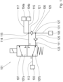
- Hydraulic block 101 shown is fluidly connected to a master cylinder 103, a means 105 for fixing the inclination, a first service brake 104a and a second service brake 104b.
- the hydraulic block 101 forms a 3/2-way valve 107, a first check valve 109, a second check valve 111 and several hydraulic lines.
- the 3/2-way valve has a first connection V1, a second connection V2 and a third connection V3.
- a first hydraulic line 113 connects the master cylinder 103 to the second port V2.
- a second hydraulic line 114 runs from the first connection V1 to a first distributor 115.
- a third hydraulic line 117 and a fourth hydraulic line 119 each lead from the first distributor 115 to a service brake 104a, 104b.
- a fifth hydraulic line 121 connects the distributor 115 and the first check valve 109 to one another.
- the second hydraulic line 114, the third hydraulic line 117, the fourth hydraulic line 119 and the fifth hydraulic line 121 are thus connected to one another in a fluid-conducting manner via the first distributor 115.
- a sixth hydraulic line 123 leads from the third connection V3 to the second check valve 111.
- the second check valve 111 is connected to a second distributor 127 via a seventh hydraulic line 125.
- the first check valve 109 is connected to the second distributor 127 via an eighth hydraulic line 129 .
- a ninth hydraulic line 131 connects the second distributor 127 to the means 107 for fixing the inclination.
- the seventh hydraulic line 125, the eighth hydraulic line 129 and the ninth hydraulic line 131 are thus connected to one another in a fluid-conducting manner via the second distributor 127.
- the first check valve 109 is oriented to allow hydraulic fluid to flow from the eighth hydraulic line 129 into the fifth hydraulic line 121 . In the opposite direction, the first hydraulic valve 109 blocks. No hydraulic fluid can therefore flow from the fifth line 121 via the first check valve 109 into the eighth hydraulic line 129 .
- the second check valve 111 allows hydraulic fluid to flow from the sixth hydraulic line 123 into the seventh hydraulic line 125 . It blocks in the opposite direction, so that no hydraulic fluid can flow from the seventh hydraulic line 125 into the sixth hydraulic line 123 .
- the 3/2-way valve 107 has two switching positions. In a first switching position 107a, the first connection V1 and the second connection V2 are connected to one another in a fluid-conducting manner. In the first switching position 107a, the third connection V3 is not connected to another connection of the 3/2-way valve 107 in a fluid-conducting manner.
- a second switching position 107b the second connection V2 and the third connection V3 are connected to one another in a fluid-conducting manner.
- the first connection V1 is not connected to another connection of the 3/2-way valve 107 in a fluid-conducting manner.
- the switching mechanism of the 3/2-way valve is spring-loaded.
- the spring force causes the 3/2-way valve 107 to assume the second switching state 107b in the rest position.
- the 3/2-way valve 107 can be transferred from the second switching state 107b to the first switching state 107a by means of an electromagnetic actuator. If the electromagnetic actuator is not energized, the spring force causes the 3/2-way valve 107 to return from the first switching state 107a to the second switching state 107b.
Landscapes
- Engineering & Computer Science (AREA)
- Physics & Mathematics (AREA)
- Transportation (AREA)
- Mechanical Engineering (AREA)
- Electromagnetism (AREA)
- Fluid Mechanics (AREA)
- Regulating Braking Force (AREA)
Description
- Die Erfindung betrifft eine Anordnung nach dem Oberbegriff von Anspruch 1, ein Verfahren nach Anspruch 8, ein Steuergerät nach Anspruch 9 und ein Computerprogramm nach Anspruch 10.
- Aus dem Stand der Technik sind mehrspurige Fahrzeuge mit einem um eine Längsachse verschwenkbaren Aufbau bekannt. Derartige Fahrzeuge werden etwa in den Druckschriften
EP 2 729 351 A1 ,EP 3 272 561 A1 ,EP 2 300 308 A1 , -
DE 10 2006 022 134 A1 ,EP 1 362 779 A2 ,EP 1 870 269 A1 ,US 2008 238 005 A2 undEP 0 876 263 A1 beschrieben. Ein Neigemechanismus des jeweiligen Fahrzeugs lässt sich blockieren, um das Fahrzeug im Stillstand zu stabilisieren und zu verhindern, dass es umfällt. Zum Aktivieren des Mechanismus ist ein entsprechendes Bedienelement vorgesehen. Auch ist es möglich, den Mechanismus automatisch zu aktivieren, wenn das Fahrzeug zum Stillstand kommt. Eine Parkbremse muss dabei separat betätigt und gelöst werden.CN 206 871 054 U offenbart eine Anordnung mit einem hydraulischen Geber, einem ersten und einem zweiten hydraulischen Nehmer, einem ersten und einem zweiten Rückschlagventil. - Der Erfindung liegt die Aufgabe zugrunde, die Betätigung einer Betriebsbremse, einer Parkbremse und eines Feststellmittels zum Blockieren eines Neigungsmechanismus eines mehrspurigen Fahrzeugs gegenüber dem Stand der Technik zu verbessern. Diese Aufgabe wird gelöst durch eine Anordnung nach Anspruch 1, ein Verfahren nach Anspruch 8, ein Steuergerät nach Anspruch 9 und ein Computerprogramm nach Anspruch 10. Bevorzugte Weiterbildungen sind in den Unteransprüchen enthalten und ergeben sich aus nachfolgender Beschreibung.
- Die Anordnung umfasst einen Geberzylinder, einen ersten Nehmerzylinder und einen zweiten Nehmerzylinder. Geberzylinder und Nehmerzylinder sind hydraulische oder pneumatische Arbeitszylinder, die mit einem Arbeitsfluid betrieben werden. Der Geberzylinder dient dazu, das Arbeitsfluid mit Druckenergie zu beaufschlagen. Die Energie wird dem Nehmerzylinder über das Arbeitsfluid zugeführt. Dier Nehmerzylinder wandelt die Energie in mechanische Energie, vorzugsweise in eine Linearbewegung.
- Erfindungsgemäß umfasst die Anordnung ein erstes Rückschlagventil und ein zweites Rückschlagventil. Rückschlagventile, auch Rückschlagarmaturen genannt, sind Mittel, die das Arbeitsfluid jeweils nur in eine Richtung - die Durchlassrichtung - strömen lassen. Entgegengesetzt zur Durchlassrichtung sperrt ein Rückschlagventil das Arbeitsfluid, sodass das Arbeitsfluid in Rückschlagrichtung nicht strömen kann. Ein Rückschlagventil weist einen Eingang und einen Ausgang auf. Das Arbeitsfluid kann von dem Eingang in Richtung des Ausgangs strömen. Eine Strömung des Arbeitsfluids von dem Ausgang in Richtung des Eingangs sperrt das Rückschlagventil.
- Die Anordnung weist darüber hinaus ein 3/2-Wegeventil auf. Dies ist ein Wegeventil mit drei Anschlüssen - einem ersten Anschluss, einem zweiten Anschluss und einem dritten Anschluss - und zwei Schaltstellungen. Befindet sich das 3/2-Wegeventil in einer ersten Schaltstellung, sind der erste Anschluss und der zweite Anschluss fluidleitend miteinander verbunden. Der dritte Anschluss ist dabei isoliert. Dies bedeutet, dass weder zwischen dem dritten Anschluss und dem ersten Anschluss noch zwischen dem dritten Anschluss und dem zweiten Anschluss eine fluidleitende Verbindung besteht.
- Befindet sich das 3/2-Wegeventil in einer zweiten Schaltstellung, sind der zweite Anschluss und der dritte Anschluss fluidleitend miteinander verbunden. Der erste Anschluss ist dann isoliert, sodass weder zwischen dem ersten Anschluss und dem zweiten Anschluss noch zwischen dem ersten Anschluss und dem dritten Anschluss eine fluidleitende Verbindung besteht.
- Sind zwei Elemente fluidleitend miteinander verbunden, besteht zwischen den Elementen eine fluidleitende Verbindung. Eine fluidleitende Verbindung zeichnet sich dadurch aus, dass sie ein mit einem Überdruck beaufschlagtes Fluid leitet. Insbesondere ist eine fluidleitende Verbindung überdruckleitend, das heißt ausgebildet, den Überdruck, mit dem das Fluid beaufschlagt ist, zu leiten. Mit Überdruck wird ein Druck bezeichnet, der den Umgebungsdruck übersteigt. Innerhalb einer fluidleitenden Verbindung kann das Arbeitsfluid in beliebige Richtungen frei strömen. Insbesondere wird die Strömung des Fluids in keine Richtung gesperrt.
- Die Anordnung umfasst mehrere fluidleitende Verbindungen. So sind der erste Anschluss des 3/2-Wegeventils, der Ausgang des ersten Rückschlagventils und der erste Nehmer über eine fluidleitende Verbindung fluid- und druckleitend miteinander verbunden. Über eine weitere fluidleitende Verbindung sind der Geber und der zweite Anschluss des 3/2-Wegeventils fluid- und druckleitend miteinander verbunden. Weiterhin verbindet eine fluidleitende Verbindung den dritten Anschluss des 3/2-Wegeventils und den Eingang des zweiten Rückschlagventils fluid- und druckleitend miteinander. Schließlich sind der Eingang des ersten Rückschlagventils, der Ausgang des zweiten Rückschlagventils und der zweite Nehmer über eine fluidleitende Verbindung fluid- und druckleitend miteinander verbunden.
- Mittels der erfindungsgemäßen Anordnung lässt sich in bevorzugten Weiterbildungen eine Betriebsbremse und/oder ein Feststellmittel betätigen. Der erste Nehmer ist betätigungswirksam mit der Betriebsbremse verbunden, sodass die Betriebsbremse über den ersten Nehmer betätigt werden kann. Der Nehmer ist also ausgebildet, die Betriebsbremse zu schließen und so eine Bremskraft aufzubringen. Vorzugsweise handelt es sich bei dem Nehmer um einen Bremskolben.
- Das Feststellmittel dient dazu, den Neigemechanismus eines Fahrzeugs der eingangs genannten Art zu blockieren. Im blockierten Zustand ist die Neigung eines Aufbaus des Fahrzeugs bezüglich der Längsachse auch bei Einwirkung äußerer Kräfte unveränderlich.
- Der zweite Nehmer ist betätigungswirksam mit dem Feststellmittel verbunden. Mittels des zweiten Nehmers lässt sich das Feststellmittel derart betätigen, sodass der Neigungsmechanismus blockiert.
- Befindet sich das 3/2-Wegeventil in der ersten Schaltstellung, lässt sich die Betriebsbremse über die Zusammenwirkung von Geber und erstem Nehmer auf herkömmliche Weise betätigen. In dem das Arbeitsfluid über den Nehmer mit einem Druck beaufschlagt wird, wird die Betriebsbremse betätigt und so ein Bremsvorgang eingeleitet. Die Betriebsbremse bleibt so lange geschlossen, wie der über den Geber aufgebrachte Druck anliegt. Das erste Rückschlagventil verhindert dabei, dass der zweite Nehmer mit dem Druck beaufschlagt wird. Entfällt der Druck, löst sich die Betriebsbremse.
- Über die zweite Schaltstellung des 3/2-Wegeventils lässt sich eine Halte- und Parkfunktion realisieren. Befindet sich das 3/2-Wegeventil in der zweiten Schaltstellung, wirkt der Geber über den ersten Nehmer und den zweiten Nehmer sowohl auf die Betriebsbremse als auch auf das Feststellmittel. Fällt der Druck, mit dem der Geber das Arbeitsfluid beaufschlagt, ab, werden die Rückschlagventile in Sperrrichtung beaufschlagt. Infolgedessen bleibt der auf den ersten Nehmer und den zweiten Nehmer wirkende Fluiddruck erhalten. Die Betriebsbremse wirkt dann als eine Parkbremse. Gleichzeitig blockiert das Feststellmittel den Neigemechanismus und verhindert, dass das Fahrzeug umkippt.
- Wird das 3/2-Wegeventil zurück in die erste Schaltstellung überführt, baut sich der Druck, mit dem der erste Nehmer und der zweite Nehmer beaufschlagt sind, über die fluidleitende Verbindung zwischen dem ersten Anschlusses und dem zweiten Anschluss in Richtung des Gebers ab. Das erste Rückschlagventil wird dabei in Durchlassrichtung beaufschlagt.
- In einer bevorzugten Weiterbildung umfasst die Anordnung ein Bedienelement zum Betätigen des Nehmers. Bei dem Bedienelement handelt es sich vorzugsweise um einen Bremshebel oder ein Bremspedal.
- Bevorzugt ist die Anordnung darüber hinaus mit einem Rückstellmechanismus weitergebildet, der das 3/2-Wegeventil mit einer Rückstellkraft beaufschlagt. Vorzugsweise wird das 3/2-Wegeventil permanent mit der Rückstellkraft beaufschlagt. Die Rückstellkraft bewirkt eine Überführung des 3/2-Wegeventils von der ersten Schaltstellung in die zweite Schaltstellung.
- Durch Verwendung eines ausfallsicheren Rückstellmechanismus lässt sich erreichen, dass die Anordnung im Fehlerfall einen sicheren Zustand einnimmt. So wird weiterbildungsgemäß im Fehlerfall durch den Rückstellmechanismus die Halte- und Parkfunktion aktiviert. Dadurch wird verhindert, dass das Fahrzeug im Fehlerfall umkippt oder unkontrolliert wegrollt. Als Rückstellmechanismus eignet sich etwa ein Federelement, insbesondere eine mechanische Feder.
- Gegen die Rückstellkraft des Rückstellmechanismus wirkt in einer bevorzugten Weiterbildung ein Aktor. Dies impliziert, dass sich das 3/2-Wegeventil mittels des Aktors von der zweiten Schaltstellung in die erste Schaltstellung überführen lässt. Der Aktor bringt dabei eine Kraft auf, die gegen die Rückstellkraft wirkt, das heißt die der Rückstellkraft entgegengerichtet ist, und die betragsmäßig größer als die Rückstellkraft ist. Vorzugsweise kommt ein elektromechanischer Aktor zum Einsatz. Bei einem Ausfall des Aktors wird die Anordnung, wie oben beschrieben, durch den Rückstellmechanismus in einen sicheren Zustand überführt.
- Bevorzugt ist die Anordnung mit einem einstückig ausgeführten Block weiterbildet. Dieser bildet ein Gehäuse des ersten Rückschlagventils, ein Gehäuse des zweiten Rückschlagventils, ein Gehäuse des 3/2-Wegeventils, die fluidleitende Verbindung zwischen dem ersten Anschluss des 3/2-Wegeventils, dem Ausgang des ersten Rückschlagventils und dem ersten Nehmer, die fluidleitende Verbindung zwischen dem Geber und dem zweiten Anschluss des 3/2-Wegeventils, die fluidleitende Verbindung zwischen dem dritten Anschluss des 3/2-Wegeventils und dem Eingang des zweiten Rückschlagventils sowie die fluidleitende Verbindung zwischen dem Eingang des ersten Rückschlagventils, dem Ausgang des zweiten Rückschlagventils und dem zweiten Nehmer aus. Der weiterbildungsgemäße Ventil- und Leitungsblock zeichnet sich durch seine Einfachheit und Robustheit aus. Insbesondere lässt sich der Block kostengünstig fertigen.
- Ein erfindungsgemäßes computerimplementiertes Verfahren dient zum Betrieb eines Fahrzeugs, vorzugsweise eines Fahrzeugs der eingangs beschriebenen Art. Das Fahrzeug weist eine erfindungsgemäße Anordnung oder eine bevorzugte Weiterbildung auf. Erfindungsgemäß wird die Fahrgeschwindigkeit des Fahrzeugs überwacht und mit einem vordefinierten Schwellwert verglichen. Unterschreitet die Fahrgeschwindigkeit den Schwellwert, wird das 3/2-Wegeventil der Anordnung von der ersten Schaltstellung in die zweite Schaltstellung überführt, sodass die Halte- und Parkfunktion aktiviert wird.
- Die Überführung des 3/2-Wegeventils von der zweiten Schaltstellung in die erste Schaltstellung erfolgt vorzugsweise auf manuellem Wege. So kann das Fahrzeug etwa ein separates Bedienelement aufweisen, bei dessen Betätigung die Überführung von der zweiten Schaltstellung in die erste Schaltstellung erfolgt. Auch ist es möglich, das 3/2-Wegeventil von der zweiten Schaltstellung in die erste Schaltstellung in Abhängigkeit von der Betätigung eines Schaltelements zur Beschleunigung des Fahrzeugs, etwa eines Gasgriffs oder Gaspedals, zu überführen.
- Ein erfindungsgemäßes Steuergerät implementiert das erfindungsgemäße Verfahren. Das Steuergerät ist also ausgebildet, ein Geschwindigkeitssignal eines Fahrzeugs, vorzugsweise eines Fahrzeugs der eingangs beschriebenen Art, das eine erfindungsgemäße Anordnung oder eine bevorzugte Weiterbildung aufweist, zu empfangen. Das Geschwindigkeitssignal wird von dem Steuergerät mit dem Schwellwert verglichen. Stellt das Steuergerät fest, dass das Geschwindigkeitssignal den Schwellwert unterschreitet, überführt das Steuergerät das 3/2-Wegeventil der Anordnung von der ersten Schaltstellung in die zweite Schaltstellung.
- Ein erfindungsgemäßes Computerprogramm ist ausgebildet, ein Steuergerät zur Ausführung des erfindungsmäßen Verfahrens zu veranlassen, wenn das Computerprogramm auf dem Steuergerät ausgeführt wird. Ein Steuergerät, auf dem das erfindungsgemäße Computerprogramm gespeichert ist, ist eine Ausführungsform des erfindungsgemäßen Steuergeräts.
- Ein bevorzugtes Ausführungsbeispiel der Erfindung ist in
Figur 1 dargestellt. Im Einzelnen zeigt: - Fig. 1
- einen Hydraulikblock.
- Der in
Figur 1 dargestellte Hydraulikblock 101 ist fluidleitend mit einem Geberzylinder 103, einem Mittel 105 zur Neigungsfixierung, einer ersten Betriebsbremse 104a und einer zweiten Betriebsbremse 104b verbunden. Der Hydraulikblock 101 bildet ein 3/2-Wegeventil 107, ein erstes Rückschlagventil 109, ein zweites Rückschlagventil 111 und mehrere Hydraulikleitungen aus. Das 3/2-Wegeventil weist einen ersten Anschluss V1, einen zweiten Anschluss V2 und einen dritten Anschluss V3 auf. - Eine erste Hydraulikleitung 113 verbindet den Geberzylinder 103 mit dem zweiten Anschluss V2. Eine zweite Hydraulikleitung 114 verläuft von dem ersten Anschluss V1 zu einem ersten Verteiler 115. Eine dritte Hydraulikleitung 117 und eine vierte Hydraulikleitung 119 führen jeweils von dem ersten Verteiler 115 zu einer Betriebsbremse 104a, 104b. Eine fünfte Hydraulikleitung 121 verbindet den Verteiler 115 und das erste Rückschlagventil 109 miteinander. Über den ersten Verteiler 115 sind somit die zweite Hydraulikleitung 114, die dritte Hydraulikleitung 117, die vierte Hydraulikleitung 119 und die fünfte Hydraulikleitung 121 fluidleitend miteinander verbunden.
- Eine sechste Hydraulikleitung 123 führt von dem dritten Anschluss V3 zu dem zweiten Rückschlagventil 111. Über eine siebte Hydraulikleitung 125 ist das zweite Rückschlagventil 111 mit einem zweiten Verteiler 127 verbunden. Weiterhin ist das erste Rückschlagventil 109 über eine achte Hydraulikleitung 129 mit dem zweiten Verteiler 127 verbunden. Eine neunte Hydraulikleitung 131 verbindet den zweiten Verteiler 127 mit dem Mittel 107 zur Neigungsfixierung. Über den zweiten Verteiler 127 sind somit die siebte Hydraulikleitung 125, die achte Hydraulikleitung 129 und die neunte Hydraulikleitung 131 fluidleitend miteinander verbunden.
- Das erste Rückschlagventil 109 ist so ausgerichtet, dass es Hydraulikflüssigkeit von der achten Hydraulikleitung 129 in die fünfte Hydraulikleitung 121 strömen lässt. In Gegenrichtung sperrt das erste Hydraulikventil 109. Von der fünften Leitung 121 kann also keine Hydraulikflüssigkeit über das erste Rückschlagventil 109 in die achte Hydraulikleitung 129 strömen.
- Das zweite Rückschlagventil 111 lässt Hydraulikflüssigkeit von der sechsten Hydraulikleitung 123 in die siebte Hydraulikleitung 125 strömen. In Gegenrichtung sperrt es, sodass keine Hydraulikflüssigkeit von der siebten Hydraulikleitung 125 in die sechste Hydraulikleitung 123 strömen kann.
- Das 3/2-Wegeventil 107 besitzt zwei Schaltstellungen. In einer ersten Schaltstellung 107a sind der ersten Anschluss V1 und der zweiten Anschluss V2 fluidleitend miteinander verbunden. Der dritte Anschluss V3 ist in der ersten Schaltstellung 107a nicht fluidleitend mit einem anderen Anschluss des 3/2-Wegeventils 107 verbunden.
- In einer zweiten Schaltstellung 107b sind der zweite Anschluss V2 und der dritte Anschluss V3 fluidleitend miteinander verbunden. Der erste Anschluss V1 ist in der zweiten Schaltstellung 107b nicht fluidleitend mit einem anderen Anschluss des 3/2-Wegeventils 107 verbunden.
- Der Schaltmechanismus des 3/2-Wegeventils ist mit einer Federkraft beaufschlagt. Die Federkraft bewirkt, dass das 3/2-Wegeventil 107 in Ruheposition den zweiten Schaltzustand 107b einnimmt. Mittels eines elektromagnetischen Aktors lässt sich das 3/2-Wegeventil 107 von dem zweiten Schaltzustand 107b in den ersten Schaltzustand 107a überführen. Ist der elektromagnetische Aktor unbestromt, bewirkt die Federkraft, dass das 3/2-Wegeventil 107 von dem ersten Schaltzustand 107a in den zweiten Schaltzustand 107b zurückkehrt.
-
- 101
- Hydraulikblock
- 103
- Geberzylinder
- 105
- Mittel zur Neigungsfixierung
- 104a
- erste Betriebsbremse
- 104b
- zweite Betriebsbremse
- 107
- 3/2-Wegeventil
- 107a
- erste Schaltstellung des 3/2-Wegeventils
- 107b
- zweite Schaltstellung des 3/2-Wegeventils
- 109
- erstes Rückschlagventil
- 111
- zweites Rückschlagventil
- 113
- erste Hydraulikleitung
- 114
- zweite Hydraulikleitung
- 115
- erster Verteiler
- 117
- dritte Hydraulikleitung
- 119
- vierte Hydraulikleitung
- 121
- fünfte Hydraulikleitung
- 123
- sechste Hydraulikleitung
- 125
- siebte Hydraulikleitung
- 127
- zweiter Verteiler
- 129
- achte Hydraulikleitung
- 131
- neunte Hydraulikleitung
Claims (10)
- Anordnung mit einem hydraulischen Geber (103), einem hydraulischen ersten Nehmer (104a, 104b) und einem zweiten Nehmer (105);einem ersten Rückschlagventil (109), einem zweiten Rückschlagventil (111), einem 3/2-Wegeventil (107), gekennzeichnet durcheine fluidleitende Verbindung (114, 115, 117, 119, 121) zwischen einem ersten Anschluss (V1) des 3/2-Wegeventils (107), einem Ausgang des ersten Rückschlagventils (109) und dem ersten Nehmer (104a, 104b), eine fluidleitende Verbindung (113) zwischen dem Geber (103) und einem zweiten Anschluss (V2) des 3/2-Wegeventils (107), eine fluidleitende Verbindung (123) zwischen einem dritten Anschluss (V3) des 3/2-Wegeventils (107) und einem Eingang des zweiten Rückschlagventils (111), und eine fluidleitende Verbindung (125, 127, 129, 131) zwischen einem Eingang des ersten Rückschlagventils (109), einem Ausgang des zweiten Rückschlagventils (111) und dem zweiten Nehmer (105); wobeider erste Anschluss (V1) und der zweite Anschluss (V2) in einer ersten Schaltstellung (107a) des 3/2-Wegeventils (107) fluidleitend miteinander verbunden sind, und wobeider zweite Anschluss (V2) und der dritte Anschluss (V3) in einer zweiten Schaltstellung (107b) des 3/2-Wegeventils (107) fluidleitend miteinander verbunden sind.
- Anordnung nach Anspruch 1; gekennzeichnet durcheine Betriebsbremse; wobeider erste Nehmer (104a, 104b) ausgebildet ist, die Betriebsbremse zu betätigen.
- Anordnung nach einem der vorhergehenden Ansprüche; gekennzeichnet durch einen Feststellmittel zum Blockieren eines Neigemechanismus eines mehrspurigen Fahrzeugs; wobei
der zweite Nehmer (105) ausgebildet ist, das Feststellmittel zu betätigen. - Anordnung nach einem der vorhergehenden Ansprüche; gekennzeichnet durch ein Bedienelement zum Betätigen des Nehmers (105).
- Anordnung nach einem der vorhergehenden Ansprüche; gekennzeichnet durch einen Rückstellmechanismus, der das 3/2-Wegeventil (107) mit einer Rückstellkraft beaufschlagt; wobei
die Rückstellkraft ein Überführung des 3/2-Wegeventil (107) von der ersten Schaltstellung (107a) in die zweite Schaltstellung (107b) bewirkt. - Anordnung nach dem vorhergehenden Anspruch; gekennzeichnet durch einen gegen die Rückstellkraft wirkenden Aktor.
- Anordnung nach einem der vorhergehenden Ansprüche; gekennzeichnet durch einen einstückig ausgeführten Block, der ein Gehäuse des ersten Rückschlagventils (109), ein Gehäuse des zweite Rückschlagventils (111), ein Gehäuse des 3/2-Wegeventils (107) und die fluidleitenden Verbindungen (114, 115, 125, 117, 119, 121, 123,125, 127, 129, 131) ausbildet.
- Computerimplementiertes Verfahren zum Betrieb eines Fahrzeugs, das eine Anordnung nach einem der vorhergehenden Ansprüche aufweist; dadurch gekennzeichnet, dass
das 3/2-Wegeventil (107) der Anordnung von der ersten Schaltstellung (107a) in die zweite Schaltstellung (107b) überführt wird, sobald die Fahrgeschwindigkeit des Fahrzeugs einen vordefinierten Schwellwert unterschreitet. - Steuergerät umfassend Mittel zur Ausführung des Verfahrens nach Anspruch 8 .
- Computerprogramm, das ausgebildet ist, ein Steuergerät nach dem vorhergehenden Anspruch zur Ausführung eines Verfahrens nach dem Verfahrensanspruch zu veranlassen.
Applications Claiming Priority (1)
| Application Number | Priority Date | Filing Date | Title |
|---|---|---|---|
| DE102021203459.4A DE102021203459B3 (de) | 2021-04-08 | 2021-04-08 | Integration von Betriebsbremse, Feststellbremse und Kippsicherung |
Publications (2)
| Publication Number | Publication Date |
|---|---|
| EP4071013A1 EP4071013A1 (de) | 2022-10-12 |
| EP4071013B1 true EP4071013B1 (de) | 2023-08-09 |
Family
ID=81328538
Family Applications (1)
| Application Number | Title | Priority Date | Filing Date |
|---|---|---|---|
| EP22167124.1A Active EP4071013B1 (de) | 2021-04-08 | 2022-04-07 | Integration von betriebsbremse, feststellbremse und kippsicherung |
Country Status (2)
| Country | Link |
|---|---|
| EP (1) | EP4071013B1 (de) |
| DE (1) | DE102021203459B3 (de) |
Family Cites Families (20)
| Publication number | Priority date | Publication date | Assignee | Title |
|---|---|---|---|---|
| US4546997A (en) | 1983-07-28 | 1985-10-15 | John Shuttleworth | Vehicle steering and suspension system |
| AT403566B (de) | 1996-01-25 | 1998-03-25 | Geiser Friedrich | Motorisiertes fahrzeug, insbesondere dreirad, mit zwei drehbar am fahrzeugramen angelenkten, gefederten schwingen |
| DE19717418C1 (de) | 1997-04-25 | 1998-10-22 | Daimler Benz Ag | Mehrspuriges Kurvenneigerfahrzeug |
| DK1363794T3 (da) | 2001-02-27 | 2006-10-02 | Piaggio & C Spa | Trehjulet köretöj med krængningsophængssystem |
| EP1362779B1 (de) | 2002-05-17 | 2011-04-20 | The Four Wheeled Motorcycle Company Limited | Motorradartiges Fahrzeug |
| WO2005075278A1 (en) | 2004-02-06 | 2005-08-18 | Phillip Ronald James | Tilting vehicle |
| DE102006022134A1 (de) | 2005-05-13 | 2006-11-30 | Harley-Davidson Motor Company Group, Inc., Milwaukee | Selbstzentrierender Rückführmechanismus |
| DE602006002816D1 (de) | 2006-06-23 | 2008-10-30 | Fondazione Torino Wireless | Fahrwerksneigemodul für Radfahrzeuge und mit einem solchen Modul ausgestattetes Radfahrzeug |
| DE102007013673B4 (de) * | 2007-03-19 | 2009-07-02 | Knorr-Bremse Systeme für Nutzfahrzeuge GmbH | Druckluftversorgungseinrichtung für ein Nutzfahrzeug und Verfahren zum Betreiben einer Druckluftversorgungseinrichtung |
| FR2933950B1 (fr) | 2008-07-21 | 2011-02-11 | Veleance | Dispositif mecanique de controle d'inclinaison |
| DE102009003396A1 (de) * | 2009-01-28 | 2010-07-29 | Continental Aktiengesellschaft | Verfahren zum Steuern der Regenerationszyklen für einen Lufttrockner in einer geschlossenen Niveauregelanlage für Fahrzeuge |
| DE102011011630B4 (de) * | 2011-02-17 | 2021-11-04 | Knorr-Bremse Systeme für Nutzfahrzeuge GmbH | Druckluftversorgungseinrichtung für ein Nutzfahrzeug und Verfahren zum Betreiben einer Druckluftversorgungseinrichtung |
| GB2492757B (en) | 2011-07-07 | 2015-12-23 | David Andrew Gale | A vehicle |
| EP3048019B1 (de) * | 2015-01-21 | 2021-08-25 | ZF CV Systems Europe BV | Druckluftversorgungsanlage für eine pneumatische Anlage |
| EP3272561A4 (de) | 2015-03-19 | 2018-03-21 | Yamaha Hatsudoki Kabushiki Kaisha | Hydraulische stossdämpfervorrichtung für fahrzeug |
| CN206860570U (zh) * | 2017-04-19 | 2018-01-09 | 青岛武晓集团股份有限公司 | 一种双作用油缸同步机构 |
| DE102017121236A1 (de) * | 2017-05-04 | 2018-11-08 | ECO Holding 1 GmbH | Hydraulikmodul mit einem Umschaltventil zum Steuern eines Hydraulikflüssigkeitsstroms eines Pleuels für eine Brennkraftmaschine mit variabler Verdichtung sowie Pleuel |
| CN206871054U (zh) * | 2017-06-30 | 2018-01-12 | 徐州徐工矿山机械有限公司 | 矿用自卸车液压辅助制动系统 |
| CN208900435U (zh) * | 2018-10-29 | 2019-05-24 | 安吉越力搬运设备有限公司 | 一种高效双联泵动力单元 |
| US11072389B2 (en) | 2019-02-22 | 2021-07-27 | Sway Motorsports Llc | Three-wheeled tilting vehicle |
-
2021
- 2021-04-08 DE DE102021203459.4A patent/DE102021203459B3/de not_active Expired - Fee Related
-
2022
- 2022-04-07 EP EP22167124.1A patent/EP4071013B1/de active Active
Also Published As
| Publication number | Publication date |
|---|---|
| EP4071013A1 (de) | 2022-10-12 |
| DE102021203459B3 (de) | 2022-08-25 |
Similar Documents
| Publication | Publication Date | Title |
|---|---|---|
| EP2643195B1 (de) | Bremsanlage für kraftfahrzeuge | |
| DE19543698C1 (de) | Bremsgestänge und Hauptbremszylinder | |
| DE102009055224B4 (de) | Hydraulische Fahrzeugbremsanlage | |
| EP2067638B2 (de) | Schaltventil für Anlagen zum Heben und Senken eines Fahrzeugaufbaus | |
| WO1994012374A1 (de) | Fluidische verbund-bremseinrichtung für einspurfahrzeuge und einspurfahrzeug mit einer derartigen bremseinrichtung | |
| DE19638102C2 (de) | Betätigungseinheit für eine elektronisch gesteuerte Fahrzeugbremsanlage | |
| DE19725298B4 (de) | Elektronisch regelbares Bremsbetätigungssystem | |
| DE102010038328A1 (de) | Bremssystem für Kraftfahrzeuge | |
| DE19950862C1 (de) | Betätigungseinheit für eine elektronisch gesteuerte Fahrzeugbremsanlage | |
| DE102007016975A1 (de) | Betätigungseinrichtung für eine elektrohydraulische Fahrzeug-Bremsanlage mit einem Pedalkraftsimulator | |
| DE102009036783B4 (de) | Nothahn, Türbetätigungsvorrichtung, Fahrzeugtüranlage, Fahrzeug und Verfahren zum Betreiben einer Fahrzeugtüranlage | |
| DE3012146C2 (de) | ||
| EP4071013B1 (de) | Integration von betriebsbremse, feststellbremse und kippsicherung | |
| EP1097074A1 (de) | Betätigungsvorrichtung für eine elektrohydraulische fahrzeugbremsanlage | |
| DE2411701A1 (de) | Einrichtung zur kraftunterstuetzung von betaetigungsorganen bei kraftfahrzeugen, insbesondere einer hydraulischen bremsanlage | |
| DE102009034170B4 (de) | Türbetätigungsventileinrichtung für eine druckmittelbetätigbare Fahrzeugtüranlage | |
| EP3700790B1 (de) | Anordnung mit einem bremskrafterzeuger und verfahren zum betreiben eines bremskrafterzeugers | |
| DE10258266B4 (de) | Betätigungseinheit | |
| DE102019201907A1 (de) | Elektronisch schlupfregelbare Fremdkraftbremsanlage | |
| DE2308306A1 (de) | Ventilmechanismus zum einbau in ein druckluft-bremssystem | |
| DE2500903A1 (de) | Steuerungssystem fuer eine bremse | |
| DE69400960T2 (de) | Hydraulischer kreislauf mit als verteiler wirkendem behälter | |
| DE3625146A1 (de) | Bremssystem mit einem hydraulikdruckgenerator des hydraulischen bremskraftverstaerkertyps | |
| DE10216692B3 (de) | Betätigungseinheit für eine elektrohydraulische Bremsanlage eines Kraftfahrzeugs | |
| DE10164319C2 (de) | Betätigungseinheit für eine hydraulische Fahrzeugbremsanlage |
Legal Events
| Date | Code | Title | Description |
|---|---|---|---|
| PUAI | Public reference made under article 153(3) epc to a published international application that has entered the european phase |
Free format text: ORIGINAL CODE: 0009012 |
|
| STAA | Information on the status of an ep patent application or granted ep patent |
Free format text: STATUS: THE APPLICATION HAS BEEN PUBLISHED |
|
| STAA | Information on the status of an ep patent application or granted ep patent |
Free format text: STATUS: REQUEST FOR EXAMINATION WAS MADE |
|
| AK | Designated contracting states |
Kind code of ref document: A1 Designated state(s): AL AT BE BG CH CY CZ DE DK EE ES FI FR GB GR HR HU IE IS IT LI LT LU LV MC MK MT NL NO PL PT RO RS SE SI SK SM TR |
|
| 17P | Request for examination filed |
Effective date: 20220912 |
|
| GRAP | Despatch of communication of intention to grant a patent |
Free format text: ORIGINAL CODE: EPIDOSNIGR1 |
|
| STAA | Information on the status of an ep patent application or granted ep patent |
Free format text: STATUS: GRANT OF PATENT IS INTENDED |
|
| INTG | Intention to grant announced |
Effective date: 20230328 |
|
| GRAS | Grant fee paid |
Free format text: ORIGINAL CODE: EPIDOSNIGR3 |
|
| GRAA | (expected) grant |
Free format text: ORIGINAL CODE: 0009210 |
|
| STAA | Information on the status of an ep patent application or granted ep patent |
Free format text: STATUS: THE PATENT HAS BEEN GRANTED |
|
| AK | Designated contracting states |
Kind code of ref document: B1 Designated state(s): AL AT BE BG CH CY CZ DE DK EE ES FI FR GB GR HR HU IE IS IT LI LT LU LV MC MK MT NL NO PL PT RO RS SE SI SK SM TR |
|
| REG | Reference to a national code |
Ref country code: GB Ref legal event code: FG4D Free format text: NOT ENGLISH |
|
| REG | Reference to a national code |
Ref country code: CH Ref legal event code: EP |
|
| REG | Reference to a national code |
Ref country code: DE Ref legal event code: R096 Ref document number: 502022000078 Country of ref document: DE |
|
| REG | Reference to a national code |
Ref country code: IE Ref legal event code: FG4D Free format text: LANGUAGE OF EP DOCUMENT: GERMAN |
|
| REG | Reference to a national code |
Ref country code: LT Ref legal event code: MG9D |
|
| REG | Reference to a national code |
Ref country code: NL Ref legal event code: MP Effective date: 20230809 |
|
| PG25 | Lapsed in a contracting state [announced via postgrant information from national office to epo] |
Ref country code: GR Free format text: LAPSE BECAUSE OF FAILURE TO SUBMIT A TRANSLATION OF THE DESCRIPTION OR TO PAY THE FEE WITHIN THE PRESCRIBED TIME-LIMIT Effective date: 20231110 |
|
| PG25 | Lapsed in a contracting state [announced via postgrant information from national office to epo] |
Ref country code: IS Free format text: LAPSE BECAUSE OF FAILURE TO SUBMIT A TRANSLATION OF THE DESCRIPTION OR TO PAY THE FEE WITHIN THE PRESCRIBED TIME-LIMIT Effective date: 20231209 |
|
| PG25 | Lapsed in a contracting state [announced via postgrant information from national office to epo] |
Ref country code: SE Free format text: LAPSE BECAUSE OF FAILURE TO SUBMIT A TRANSLATION OF THE DESCRIPTION OR TO PAY THE FEE WITHIN THE PRESCRIBED TIME-LIMIT Effective date: 20230809 Ref country code: RS Free format text: LAPSE BECAUSE OF FAILURE TO SUBMIT A TRANSLATION OF THE DESCRIPTION OR TO PAY THE FEE WITHIN THE PRESCRIBED TIME-LIMIT Effective date: 20230809 Ref country code: PT Free format text: LAPSE BECAUSE OF FAILURE TO SUBMIT A TRANSLATION OF THE DESCRIPTION OR TO PAY THE FEE WITHIN THE PRESCRIBED TIME-LIMIT Effective date: 20231211 Ref country code: NO Free format text: LAPSE BECAUSE OF FAILURE TO SUBMIT A TRANSLATION OF THE DESCRIPTION OR TO PAY THE FEE WITHIN THE PRESCRIBED TIME-LIMIT Effective date: 20231109 Ref country code: NL Free format text: LAPSE BECAUSE OF FAILURE TO SUBMIT A TRANSLATION OF THE DESCRIPTION OR TO PAY THE FEE WITHIN THE PRESCRIBED TIME-LIMIT Effective date: 20230809 Ref country code: LV Free format text: LAPSE BECAUSE OF FAILURE TO SUBMIT A TRANSLATION OF THE DESCRIPTION OR TO PAY THE FEE WITHIN THE PRESCRIBED TIME-LIMIT Effective date: 20230809 Ref country code: LT Free format text: LAPSE BECAUSE OF FAILURE TO SUBMIT A TRANSLATION OF THE DESCRIPTION OR TO PAY THE FEE WITHIN THE PRESCRIBED TIME-LIMIT Effective date: 20230809 Ref country code: IS Free format text: LAPSE BECAUSE OF FAILURE TO SUBMIT A TRANSLATION OF THE DESCRIPTION OR TO PAY THE FEE WITHIN THE PRESCRIBED TIME-LIMIT Effective date: 20231209 Ref country code: HR Free format text: LAPSE BECAUSE OF FAILURE TO SUBMIT A TRANSLATION OF THE DESCRIPTION OR TO PAY THE FEE WITHIN THE PRESCRIBED TIME-LIMIT Effective date: 20230809 Ref country code: GR Free format text: LAPSE BECAUSE OF FAILURE TO SUBMIT A TRANSLATION OF THE DESCRIPTION OR TO PAY THE FEE WITHIN THE PRESCRIBED TIME-LIMIT Effective date: 20231110 Ref country code: FI Free format text: LAPSE BECAUSE OF FAILURE TO SUBMIT A TRANSLATION OF THE DESCRIPTION OR TO PAY THE FEE WITHIN THE PRESCRIBED TIME-LIMIT Effective date: 20230809 |
|
| PG25 | Lapsed in a contracting state [announced via postgrant information from national office to epo] |
Ref country code: PL Free format text: LAPSE BECAUSE OF FAILURE TO SUBMIT A TRANSLATION OF THE DESCRIPTION OR TO PAY THE FEE WITHIN THE PRESCRIBED TIME-LIMIT Effective date: 20230809 |
|
| PG25 | Lapsed in a contracting state [announced via postgrant information from national office to epo] |
Ref country code: ES Free format text: LAPSE BECAUSE OF FAILURE TO SUBMIT A TRANSLATION OF THE DESCRIPTION OR TO PAY THE FEE WITHIN THE PRESCRIBED TIME-LIMIT Effective date: 20230809 |
|
| PG25 | Lapsed in a contracting state [announced via postgrant information from national office to epo] |
Ref country code: SM Free format text: LAPSE BECAUSE OF FAILURE TO SUBMIT A TRANSLATION OF THE DESCRIPTION OR TO PAY THE FEE WITHIN THE PRESCRIBED TIME-LIMIT Effective date: 20230809 Ref country code: RO Free format text: LAPSE BECAUSE OF FAILURE TO SUBMIT A TRANSLATION OF THE DESCRIPTION OR TO PAY THE FEE WITHIN THE PRESCRIBED TIME-LIMIT Effective date: 20230809 Ref country code: ES Free format text: LAPSE BECAUSE OF FAILURE TO SUBMIT A TRANSLATION OF THE DESCRIPTION OR TO PAY THE FEE WITHIN THE PRESCRIBED TIME-LIMIT Effective date: 20230809 Ref country code: EE Free format text: LAPSE BECAUSE OF FAILURE TO SUBMIT A TRANSLATION OF THE DESCRIPTION OR TO PAY THE FEE WITHIN THE PRESCRIBED TIME-LIMIT Effective date: 20230809 Ref country code: DK Free format text: LAPSE BECAUSE OF FAILURE TO SUBMIT A TRANSLATION OF THE DESCRIPTION OR TO PAY THE FEE WITHIN THE PRESCRIBED TIME-LIMIT Effective date: 20230809 Ref country code: CZ Free format text: LAPSE BECAUSE OF FAILURE TO SUBMIT A TRANSLATION OF THE DESCRIPTION OR TO PAY THE FEE WITHIN THE PRESCRIBED TIME-LIMIT Effective date: 20230809 Ref country code: SK Free format text: LAPSE BECAUSE OF FAILURE TO SUBMIT A TRANSLATION OF THE DESCRIPTION OR TO PAY THE FEE WITHIN THE PRESCRIBED TIME-LIMIT Effective date: 20230809 |
|
| REG | Reference to a national code |
Ref country code: DE Ref legal event code: R097 Ref document number: 502022000078 Country of ref document: DE |
|
| PG25 | Lapsed in a contracting state [announced via postgrant information from national office to epo] |
Ref country code: IT Free format text: LAPSE BECAUSE OF FAILURE TO SUBMIT A TRANSLATION OF THE DESCRIPTION OR TO PAY THE FEE WITHIN THE PRESCRIBED TIME-LIMIT Effective date: 20230809 |
|
| PLBE | No opposition filed within time limit |
Free format text: ORIGINAL CODE: 0009261 |
|
| STAA | Information on the status of an ep patent application or granted ep patent |
Free format text: STATUS: NO OPPOSITION FILED WITHIN TIME LIMIT |
|
| 26N | No opposition filed |
Effective date: 20240513 |
|
| PG25 | Lapsed in a contracting state [announced via postgrant information from national office to epo] |
Ref country code: SI Free format text: LAPSE BECAUSE OF FAILURE TO SUBMIT A TRANSLATION OF THE DESCRIPTION OR TO PAY THE FEE WITHIN THE PRESCRIBED TIME-LIMIT Effective date: 20230809 |
|
| REG | Reference to a national code |
Ref country code: DE Ref legal event code: R119 Ref document number: 502022000078 Country of ref document: DE |
|
| PG25 | Lapsed in a contracting state [announced via postgrant information from national office to epo] |
Ref country code: BG Free format text: LAPSE BECAUSE OF FAILURE TO SUBMIT A TRANSLATION OF THE DESCRIPTION OR TO PAY THE FEE WITHIN THE PRESCRIBED TIME-LIMIT Effective date: 20230809 |
|
| PG25 | Lapsed in a contracting state [announced via postgrant information from national office to epo] |
Ref country code: MC Free format text: LAPSE BECAUSE OF FAILURE TO SUBMIT A TRANSLATION OF THE DESCRIPTION OR TO PAY THE FEE WITHIN THE PRESCRIBED TIME-LIMIT Effective date: 20230809 |
|
| PG25 | Lapsed in a contracting state [announced via postgrant information from national office to epo] |
Ref country code: MC Free format text: LAPSE BECAUSE OF FAILURE TO SUBMIT A TRANSLATION OF THE DESCRIPTION OR TO PAY THE FEE WITHIN THE PRESCRIBED TIME-LIMIT Effective date: 20230809 Ref country code: BG Free format text: LAPSE BECAUSE OF FAILURE TO SUBMIT A TRANSLATION OF THE DESCRIPTION OR TO PAY THE FEE WITHIN THE PRESCRIBED TIME-LIMIT Effective date: 20230809 |
|
| PG25 | Lapsed in a contracting state [announced via postgrant information from national office to epo] |
Ref country code: LU Free format text: LAPSE BECAUSE OF NON-PAYMENT OF DUE FEES Effective date: 20240407 |
|
| REG | Reference to a national code |
Ref country code: BE Ref legal event code: MM Effective date: 20240430 |
|
| PG25 | Lapsed in a contracting state [announced via postgrant information from national office to epo] |
Ref country code: LU Free format text: LAPSE BECAUSE OF NON-PAYMENT OF DUE FEES Effective date: 20240407 |
|
| PG25 | Lapsed in a contracting state [announced via postgrant information from national office to epo] |
Ref country code: DE Free format text: LAPSE BECAUSE OF NON-PAYMENT OF DUE FEES Effective date: 20241105 |
|
| PG25 | Lapsed in a contracting state [announced via postgrant information from national office to epo] |
Ref country code: BE Free format text: LAPSE BECAUSE OF NON-PAYMENT OF DUE FEES Effective date: 20240430 |
|
| PG25 | Lapsed in a contracting state [announced via postgrant information from national office to epo] |
Ref country code: FR Free format text: LAPSE BECAUSE OF NON-PAYMENT OF DUE FEES Effective date: 20240430 |
|
| PG25 | Lapsed in a contracting state [announced via postgrant information from national office to epo] |
Ref country code: FR Free format text: LAPSE BECAUSE OF NON-PAYMENT OF DUE FEES Effective date: 20240430 Ref country code: DE Free format text: LAPSE BECAUSE OF NON-PAYMENT OF DUE FEES Effective date: 20241105 Ref country code: BE Free format text: LAPSE BECAUSE OF NON-PAYMENT OF DUE FEES Effective date: 20240430 |
|
| PG25 | Lapsed in a contracting state [announced via postgrant information from national office to epo] |
Ref country code: IE Free format text: LAPSE BECAUSE OF NON-PAYMENT OF DUE FEES Effective date: 20240407 |
|
| PGFP | Annual fee paid to national office [announced via postgrant information from national office to epo] |
Ref country code: AT Payment date: 20250721 Year of fee payment: 4 |
|
| PG25 | Lapsed in a contracting state [announced via postgrant information from national office to epo] |
Ref country code: CY Free format text: LAPSE BECAUSE OF FAILURE TO SUBMIT A TRANSLATION OF THE DESCRIPTION OR TO PAY THE FEE WITHIN THE PRESCRIBED TIME-LIMIT; INVALID AB INITIO Effective date: 20220407 |
|
| PG25 | Lapsed in a contracting state [announced via postgrant information from national office to epo] |
Ref country code: HU Free format text: LAPSE BECAUSE OF FAILURE TO SUBMIT A TRANSLATION OF THE DESCRIPTION OR TO PAY THE FEE WITHIN THE PRESCRIBED TIME-LIMIT; INVALID AB INITIO Effective date: 20220407 |
|
| REG | Reference to a national code |
Ref country code: CH Ref legal event code: H13 Free format text: ST27 STATUS EVENT CODE: U-0-0-H10-H13 (AS PROVIDED BY THE NATIONAL OFFICE) Effective date: 20251125 |
|
| PG25 | Lapsed in a contracting state [announced via postgrant information from national office to epo] |
Ref country code: CH Free format text: LAPSE BECAUSE OF NON-PAYMENT OF DUE FEES Effective date: 20250430 |