EP4070768A1 - Pflaster zur verwendung im rahmen einer intramuskulären injektion, insbesondere einer impfung - Google Patents
Pflaster zur verwendung im rahmen einer intramuskulären injektion, insbesondere einer impfung Download PDFInfo
- Publication number
- EP4070768A1 EP4070768A1 EP22167163.9A EP22167163A EP4070768A1 EP 4070768 A1 EP4070768 A1 EP 4070768A1 EP 22167163 A EP22167163 A EP 22167163A EP 4070768 A1 EP4070768 A1 EP 4070768A1
- Authority
- EP
- European Patent Office
- Prior art keywords
- patient
- outside
- plaster
- patch
- opening
- Prior art date
- Legal status (The legal status is an assumption and is not a legal conclusion. Google has not performed a legal analysis and makes no representation as to the accuracy of the status listed.)
- Granted
Links
Images



Classifications
-
- A—HUMAN NECESSITIES
- A61—MEDICAL OR VETERINARY SCIENCE; HYGIENE
- A61L—METHODS OR APPARATUS FOR STERILISING MATERIALS OR OBJECTS IN GENERAL; DISINFECTION, STERILISATION OR DEODORISATION OF AIR; CHEMICAL ASPECTS OF BANDAGES, DRESSINGS, ABSORBENT PADS OR SURGICAL ARTICLES; MATERIALS FOR BANDAGES, DRESSINGS, ABSORBENT PADS OR SURGICAL ARTICLES
- A61L15/00—Chemical aspects of, or use of materials for, bandages, dressings or absorbent pads
- A61L15/16—Bandages, dressings or absorbent pads for physiological fluids such as urine or blood, e.g. sanitary towels, tampons
- A61L15/42—Use of materials characterised by their function or physical properties
- A61L15/44—Medicaments
-
- A—HUMAN NECESSITIES
- A61—MEDICAL OR VETERINARY SCIENCE; HYGIENE
- A61F—FILTERS IMPLANTABLE INTO BLOOD VESSELS; PROSTHESES; DEVICES PROVIDING PATENCY TO, OR PREVENTING COLLAPSING OF, TUBULAR STRUCTURES OF THE BODY, e.g. STENTS; ORTHOPAEDIC, NURSING OR CONTRACEPTIVE DEVICES; FOMENTATION; TREATMENT OR PROTECTION OF EYES OR EARS; BANDAGES, DRESSINGS OR ABSORBENT PADS; FIRST-AID KITS
- A61F13/00—Bandages or dressings; Absorbent pads
- A61F13/02—Adhesive bandages or dressings
- A61F13/0203—Adhesive bandages or dressings with fluid retention members
-
- A—HUMAN NECESSITIES
- A61—MEDICAL OR VETERINARY SCIENCE; HYGIENE
- A61F—FILTERS IMPLANTABLE INTO BLOOD VESSELS; PROSTHESES; DEVICES PROVIDING PATENCY TO, OR PREVENTING COLLAPSING OF, TUBULAR STRUCTURES OF THE BODY, e.g. STENTS; ORTHOPAEDIC, NURSING OR CONTRACEPTIVE DEVICES; FOMENTATION; TREATMENT OR PROTECTION OF EYES OR EARS; BANDAGES, DRESSINGS OR ABSORBENT PADS; FIRST-AID KITS
- A61F13/00—Bandages or dressings; Absorbent pads
- A61F13/00051—Accessories for dressings
- A61F13/00063—Accessories for dressings comprising medicaments or additives, e.g. odor control, PH control, debriding, antimicrobic
-
- A—HUMAN NECESSITIES
- A61—MEDICAL OR VETERINARY SCIENCE; HYGIENE
- A61L—METHODS OR APPARATUS FOR STERILISING MATERIALS OR OBJECTS IN GENERAL; DISINFECTION, STERILISATION OR DEODORISATION OF AIR; CHEMICAL ASPECTS OF BANDAGES, DRESSINGS, ABSORBENT PADS OR SURGICAL ARTICLES; MATERIALS FOR BANDAGES, DRESSINGS, ABSORBENT PADS OR SURGICAL ARTICLES
- A61L15/00—Chemical aspects of, or use of materials for, bandages, dressings or absorbent pads
- A61L15/16—Bandages, dressings or absorbent pads for physiological fluids such as urine or blood, e.g. sanitary towels, tampons
- A61L15/22—Bandages, dressings or absorbent pads for physiological fluids such as urine or blood, e.g. sanitary towels, tampons containing macromolecular materials
- A61L15/30—Rubbers or their derivatives
-
- B—PERFORMING OPERATIONS; TRANSPORTING
- B32—LAYERED PRODUCTS
- B32B—LAYERED PRODUCTS, i.e. PRODUCTS BUILT-UP OF STRATA OF FLAT OR NON-FLAT, e.g. CELLULAR OR HONEYCOMB, FORM
- B32B3/00—Layered products comprising a layer with external or internal discontinuities or unevennesses, or a layer of non-planar shape; Layered products comprising a layer having particular features of form
- B32B3/26—Layered products comprising a layer with external or internal discontinuities or unevennesses, or a layer of non-planar shape; Layered products comprising a layer having particular features of form characterised by a particular shape of the outline of the cross-section of a continuous layer; characterised by a layer with cavities or internal voids ; characterised by an apertured layer
- B32B3/266—Layered products comprising a layer with external or internal discontinuities or unevennesses, or a layer of non-planar shape; Layered products comprising a layer having particular features of form characterised by a particular shape of the outline of the cross-section of a continuous layer; characterised by a layer with cavities or internal voids ; characterised by an apertured layer characterised by an apertured layer, the apertures going through the whole thickness of the layer, e.g. expanded metal, perforated layer, slit layer regular cells B32B3/12
-
- B—PERFORMING OPERATIONS; TRANSPORTING
- B32—LAYERED PRODUCTS
- B32B—LAYERED PRODUCTS, i.e. PRODUCTS BUILT-UP OF STRATA OF FLAT OR NON-FLAT, e.g. CELLULAR OR HONEYCOMB, FORM
- B32B7/00—Layered products characterised by the relation between layers; Layered products characterised by the relative orientation of features between layers, or by the relative values of a measurable parameter between layers, i.e. products comprising layers having different physical, chemical or physicochemical properties; Layered products characterised by the interconnection of layers
- B32B7/04—Interconnection of layers
- B32B7/06—Interconnection of layers permitting easy separation
-
- B—PERFORMING OPERATIONS; TRANSPORTING
- B32—LAYERED PRODUCTS
- B32B—LAYERED PRODUCTS, i.e. PRODUCTS BUILT-UP OF STRATA OF FLAT OR NON-FLAT, e.g. CELLULAR OR HONEYCOMB, FORM
- B32B7/00—Layered products characterised by the relation between layers; Layered products characterised by the relative orientation of features between layers, or by the relative values of a measurable parameter between layers, i.e. products comprising layers having different physical, chemical or physicochemical properties; Layered products characterised by the interconnection of layers
- B32B7/04—Interconnection of layers
- B32B7/12—Interconnection of layers using interposed adhesives or interposed materials with bonding properties
-
- A—HUMAN NECESSITIES
- A61—MEDICAL OR VETERINARY SCIENCE; HYGIENE
- A61F—FILTERS IMPLANTABLE INTO BLOOD VESSELS; PROSTHESES; DEVICES PROVIDING PATENCY TO, OR PREVENTING COLLAPSING OF, TUBULAR STRUCTURES OF THE BODY, e.g. STENTS; ORTHOPAEDIC, NURSING OR CONTRACEPTIVE DEVICES; FOMENTATION; TREATMENT OR PROTECTION OF EYES OR EARS; BANDAGES, DRESSINGS OR ABSORBENT PADS; FIRST-AID KITS
- A61F13/00—Bandages or dressings; Absorbent pads
- A61F2013/00361—Plasters
- A61F2013/00365—Plasters use
-
- A—HUMAN NECESSITIES
- A61—MEDICAL OR VETERINARY SCIENCE; HYGIENE
- A61F—FILTERS IMPLANTABLE INTO BLOOD VESSELS; PROSTHESES; DEVICES PROVIDING PATENCY TO, OR PREVENTING COLLAPSING OF, TUBULAR STRUCTURES OF THE BODY, e.g. STENTS; ORTHOPAEDIC, NURSING OR CONTRACEPTIVE DEVICES; FOMENTATION; TREATMENT OR PROTECTION OF EYES OR EARS; BANDAGES, DRESSINGS OR ABSORBENT PADS; FIRST-AID KITS
- A61F13/00—Bandages or dressings; Absorbent pads
- A61F2013/00361—Plasters
- A61F2013/00365—Plasters use
- A61F2013/00412—Plasters use for use with needles, tubes or catheters
-
- A—HUMAN NECESSITIES
- A61—MEDICAL OR VETERINARY SCIENCE; HYGIENE
- A61F—FILTERS IMPLANTABLE INTO BLOOD VESSELS; PROSTHESES; DEVICES PROVIDING PATENCY TO, OR PREVENTING COLLAPSING OF, TUBULAR STRUCTURES OF THE BODY, e.g. STENTS; ORTHOPAEDIC, NURSING OR CONTRACEPTIVE DEVICES; FOMENTATION; TREATMENT OR PROTECTION OF EYES OR EARS; BANDAGES, DRESSINGS OR ABSORBENT PADS; FIRST-AID KITS
- A61F13/00—Bandages or dressings; Absorbent pads
- A61F2013/00361—Plasters
- A61F2013/00544—Plasters form or structure
-
- A—HUMAN NECESSITIES
- A61—MEDICAL OR VETERINARY SCIENCE; HYGIENE
- A61F—FILTERS IMPLANTABLE INTO BLOOD VESSELS; PROSTHESES; DEVICES PROVIDING PATENCY TO, OR PREVENTING COLLAPSING OF, TUBULAR STRUCTURES OF THE BODY, e.g. STENTS; ORTHOPAEDIC, NURSING OR CONTRACEPTIVE DEVICES; FOMENTATION; TREATMENT OR PROTECTION OF EYES OR EARS; BANDAGES, DRESSINGS OR ABSORBENT PADS; FIRST-AID KITS
- A61F13/00—Bandages or dressings; Absorbent pads
- A61F2013/00361—Plasters
- A61F2013/00655—Plasters adhesive
- A61F2013/00714—Plasters adhesive adhesives for mucosae
-
- A—HUMAN NECESSITIES
- A61—MEDICAL OR VETERINARY SCIENCE; HYGIENE
- A61F—FILTERS IMPLANTABLE INTO BLOOD VESSELS; PROSTHESES; DEVICES PROVIDING PATENCY TO, OR PREVENTING COLLAPSING OF, TUBULAR STRUCTURES OF THE BODY, e.g. STENTS; ORTHOPAEDIC, NURSING OR CONTRACEPTIVE DEVICES; FOMENTATION; TREATMENT OR PROTECTION OF EYES OR EARS; BANDAGES, DRESSINGS OR ABSORBENT PADS; FIRST-AID KITS
- A61F13/00—Bandages or dressings; Absorbent pads
- A61F2013/00361—Plasters
- A61F2013/00795—Plasters special helping devices
-
- A—HUMAN NECESSITIES
- A61—MEDICAL OR VETERINARY SCIENCE; HYGIENE
- A61L—METHODS OR APPARATUS FOR STERILISING MATERIALS OR OBJECTS IN GENERAL; DISINFECTION, STERILISATION OR DEODORISATION OF AIR; CHEMICAL ASPECTS OF BANDAGES, DRESSINGS, ABSORBENT PADS OR SURGICAL ARTICLES; MATERIALS FOR BANDAGES, DRESSINGS, ABSORBENT PADS OR SURGICAL ARTICLES
- A61L2300/00—Biologically active materials used in bandages, wound dressings, absorbent pads or medical devices
- A61L2300/40—Biologically active materials used in bandages, wound dressings, absorbent pads or medical devices characterised by a specific therapeutic activity or mode of action
- A61L2300/402—Anaestetics, analgesics, e.g. lidocaine
-
- A—HUMAN NECESSITIES
- A61—MEDICAL OR VETERINARY SCIENCE; HYGIENE
- A61L—METHODS OR APPARATUS FOR STERILISING MATERIALS OR OBJECTS IN GENERAL; DISINFECTION, STERILISATION OR DEODORISATION OF AIR; CHEMICAL ASPECTS OF BANDAGES, DRESSINGS, ABSORBENT PADS OR SURGICAL ARTICLES; MATERIALS FOR BANDAGES, DRESSINGS, ABSORBENT PADS OR SURGICAL ARTICLES
- A61L2300/00—Biologically active materials used in bandages, wound dressings, absorbent pads or medical devices
- A61L2300/40—Biologically active materials used in bandages, wound dressings, absorbent pads or medical devices characterised by a specific therapeutic activity or mode of action
- A61L2300/404—Biocides, antimicrobial agents, antiseptic agents
-
- A—HUMAN NECESSITIES
- A61—MEDICAL OR VETERINARY SCIENCE; HYGIENE
- A61L—METHODS OR APPARATUS FOR STERILISING MATERIALS OR OBJECTS IN GENERAL; DISINFECTION, STERILISATION OR DEODORISATION OF AIR; CHEMICAL ASPECTS OF BANDAGES, DRESSINGS, ABSORBENT PADS OR SURGICAL ARTICLES; MATERIALS FOR BANDAGES, DRESSINGS, ABSORBENT PADS OR SURGICAL ARTICLES
- A61L2300/00—Biologically active materials used in bandages, wound dressings, absorbent pads or medical devices
- A61L2300/40—Biologically active materials used in bandages, wound dressings, absorbent pads or medical devices characterised by a specific therapeutic activity or mode of action
- A61L2300/41—Anti-inflammatory agents, e.g. NSAIDs
-
- B—PERFORMING OPERATIONS; TRANSPORTING
- B32—LAYERED PRODUCTS
- B32B—LAYERED PRODUCTS, i.e. PRODUCTS BUILT-UP OF STRATA OF FLAT OR NON-FLAT, e.g. CELLULAR OR HONEYCOMB, FORM
- B32B2307/00—Properties of the layers or laminate
- B32B2307/70—Other properties
- B32B2307/724—Permeability to gases, adsorption
-
- B—PERFORMING OPERATIONS; TRANSPORTING
- B32—LAYERED PRODUCTS
- B32B—LAYERED PRODUCTS, i.e. PRODUCTS BUILT-UP OF STRATA OF FLAT OR NON-FLAT, e.g. CELLULAR OR HONEYCOMB, FORM
- B32B2556/00—Patches, e.g. medical patches, repair patches
Definitions
- the invention relates to a patch for use in the context of an intramuscular injection, in particular a vaccination.
- a liquid medicine is injected into a skeletal muscle.
- the injection is usually given in the upper arm (musculus deltoideus), the thigh (musculus vastus lateralis) or the buttocks (musculus gluteus maximus).
- the intended puncture site is first disinfected.
- the liquid drug is then injected into the skeletal muscle using a cannula or syringe, in particular a disposable syringe.
- the puncture site is covered with a swab, which in turn is fixed with adhesive tape or plaster until the puncture site has closed.
- the object of the invention is to simplify the implementation of an intramuscular injection, in particular its preparation and aftercare, and to reduce the time required for this.
- a patch for use in the context of an intramuscular injection, in particular a vaccination with a patient side and an outer side, comprising an adhesive layer on the patient side for attaching the patch to the skin of a patient, an absorbent wound pad on the patient side im Area of an intended puncture site of the intramuscular injection, wherein the absorbent pad has absorbed a disinfectant, and an opening on the outside in the area of the absorbent pad on the patient's side for the injection needle.
- the patch according to the invention is adhered to the patient's skin by means of the adhesive layer on the patient's side in preparation for the intramuscular injection.
- the plaster is stuck onto the patient's skin in such a way that the absorbent wound pad on the patient's side is arranged in the area of the intended puncture site for the intramuscular injection. Because the absorbent wound dressing has absorbed a disinfectant, it automatically becomes the intended one Puncture site disinfected.
- the intramuscular injection can therefore be carried out through the opening on the outside of the patch after the patch has been applied to the patient's skin in the area of the intended puncture site. After the intramuscular injection, the injection needle is pulled out of the puncture site.
- the patch according to the invention thus simplifies the preparation and follow-up treatment of an intramuscular injection, so that it can be carried out more quickly.
- the plaster according to the invention is particularly suitable for carrying out intramuscular injections, since the injection needle does not have to be inserted specifically into a blood vessel, but only into a larger muscle.
- the precise puncture site can therefore be at least partially or even completely covered by the patch while the intramuscular injection is being carried out.
- the opening is closed on the outside with a membrane, which prevents disinfectant from escaping through the opening and enables it to be pierced with the injection needle. This ensures that the intended puncture site is disinfected by the disinfectant and that it does not escape through the opening on the outside.
- the injection needle can be pierced through the membrane.
- the membrane is preferably designed in such a way that it is not destroyed by the thin injection needle, but instead closes again after the injection.
- the membrane consists of a silicone.
- the opening is closed on the outside with a cover which can be removed to carry out the injection.
- the cover is expediently designed to prevent disinfectant from escaping through the opening on the outside.
- the cover of the opening on the outside can be removed to perform the intramuscular injection.
- the cover is designed to close the opening again on the outside after the injection.
- the opening on the outside of the plaster can thus be closed again after the intramuscular injection, which means that disinfectant or wound fluid or blood can escape is avoided. Furthermore, the puncture site is better protected from external influences.
- the cover is designed as a tab which is permanently connected to the outside of the patch at an edge area.
- the tab is thus permanently bonded to the outside of the patch and cannot become misplaced, damaged, soiled or the like while the intramuscular injection is being performed. If the tab were not permanently attached to the outside of the patch, it would need to be stored in a safe and clean place during the intramuscular injection.
- the cover is at least partially self-adhesive. This allows the cover, for example, to be repeatedly attached to the outside of the patch to close the opening of the outside of the patch before and after the intramuscular injection.
- the outside of the patch in the area where the covering is connected to the outside of the patch, may comprise an additional coating or the like, which facilitates connecting and disconnecting the covering to the outside of the patch.
- the absorbent wound dressing on the patient's side is arranged on the cover in the area of the opening on the outside.
- the absorbent wound dressing is thus removed in the area of the opening on the outside together with the cover in order to carry out the intramuscular injection.
- the injection needle is inserted directly into the patient's skin without having to penetrate the absorbent wound dressing. This prevents particles of the wound dressing from sticking to the injection needle during insertion.
- the opening is preferably closed again with the cover and the puncture site is correspondingly covered by the absorbent wound dressing.
- the absorbent wound dressing also includes an anesthetic and/or painkiller for pre-treatment or after-treatment of the puncture site of the intramuscular injection.
- an anesthetic and/or painkiller for pre-treatment or after-treatment of the puncture site of the intramuscular injection.
- This makes the intramuscular injection as painless as possible for the patient.
- different covers with absorbent wound dressings are used, each of which has absorbed different substances, for example a disinfectant and anesthetic for pre-treatment and a disinfectant and analgesic for post-treatment.
- Other combinations of substances and active ingredients are also conceivable.
- the adhesive layer completely encloses the puncture site on the patient's side.
- the adhesive layer is arranged all around the edge on the patient's side, while the absorbent wound dressing for the intended puncture site is arranged in the middle.
- the intended puncture site is thus protected from external influences from all sides and no disinfectant from the absorbent wound dressing can escape over the edge area.
- the patch comprises a backing layer on the patient side, which is removed before the patch is applied to the patient's skin.
- backing layers are known from wound plasters and protect the adhesive layer and wound dressing on the patient's side before the plaster is applied to the patient's skin.
- This backing layer is usually made in two parts, with part of the backing layer first being removed and the patch being stuck onto the patient's skin in the region of the removed backing layer.
- the second, non-removed part of the carrier layer can be used for handling without touching the underlying adhesive layer.
- the second part of the backing layer is then removed and the patch is fully adhered to the patient's skin.
- the backing layer is preferably designed to be liquid-tight, so that no liquid gets to the adhesive layer or the absorbent wound dressing and the disinfectant from the absorbent wound dressing cannot escape.
- the plaster has a round, oval, square, rectangular or polygonal shape.
- the absorbent wound dressing is preferably arranged centrally on the patient side of the patch. This allows the plaster, in particular the absorbent wound dressing, to be placed more precisely at the intended puncture site.
- the plaster is packed in an outer packaging in order to protect the plaster from external influences before use.
- This is also known, for example, from adhesive plasters.
- the plaster according to the invention is preferably designed to be breathable, so that the skin underneath the plaster can breathe. This speeds up the closing of the puncture site.
- the wound dressing is expediently designed in such a way that it does not adhere to the wound at the puncture site.
- This configuration is also known, for example, from adhesive plasters.
- 1 shows a first embodiment of a plaster 1 according to the invention for use in the context of an intramuscular injection, in particular a vaccination, with a patient side 2 and an outer side 3.
- 1 shows a view of the patient side 2 of the patch 1.
- the patient side 2 of the plaster 1 comprises an adhesive layer 4 for attaching the plaster 1 to the skin of a patient and an absorbent wound pad 5 in the area of the intended puncture site for the intramuscular injection.
- the adhesive layer 4 is designed in accordance with the known plasters. Again 1 can be seen, the adhesive layer 4 is arranged on the entire circumference of the patch 1 and therefore completely encloses the puncture site.
- the absorbent wound dressing 5 which is surrounded by the adhesive layer 4 , is arranged in the middle of the patient's side 2 .
- the absorbent wound dressing 5 has incorporated a disinfectant in order to disinfect the puncture site of the intramuscular injection as soon as the patch 1 has been stuck onto the patient's skin. Expediently, the absorbent wound dressing 5 has absorbed a liquid disinfectant.
- the absorbent wound dressing 5 also includes an anesthetic and/or painkiller for pretreatment or aftertreatment of the puncture site of the intramuscular injection.
- the anesthetic and/or painkiller is preferably a liquid that has been absorbed by the absorbent wound dressing 5 .
- these can be cooling agents that have an anesthetic and pain-relieving effect.
- FIG 12 shows a view of the outside 3 of the first embodiment of the patch 1 according to the invention 1 .
- the outside 3 of the patch 1 has an opening 6 in the area of the absorbent wound dressing on the patient's side 2 for the injection needle.
- the absorbent wound dressing 5 is visible through the opening 6 .
- the injection needle is inserted through the opening 6 and the absorbent wound pad 5 into the patient's underlying skin.
- the plaster 1 according to the invention is placed on the patient's skin in such a way that the opening 6 is in the area of the intended puncture site, in particular in the area of the upper arm (musculus deltoideus), the thigh (musculus vastus lateralis) or the buttocks (musculus gluteus maxims). or minimum).
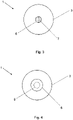
- FIG 3 shows a view of an outside 3 of a second embodiment of a patch 1 according to the invention.
- the second embodiment of FIG 3 differs from the first embodiment of FIGS Figures 1 and 2 in that the opening 6 is closed on the outside 3 with a membrane 7 .
- the membrane 7 prevents the disinfectant from escaping through the opening 6 and at the same time allows the injection needle to be pierced. Because of the membrane 7, the absorbent wound dressing 5 is not visible from the outside 3 unless the membrane 7 is transparent.
- the patient side 2 of the second embodiment 3 is, for example, identical to patient side 2 of the first embodiment, as in FIG 1 shown.
- FIG 4 shows a view of an outside 3 of a third embodiment of a patch 1 according to the invention.
- the opening 6 on the outside 3 is closed with a cover 8 .
- the cover 8 can be removed to carry out the intramuscular injection.
- the cover 8 is expediently designed to close the opening 6 again after the injection.
- the cover 8 is at least partially self-adhesive, particularly in the area where the cover 8 is attached to the outside 3 of the plaster 1 .
- FIG 5 shows a detailed view of the cover 8 from the patient's side 2, ie the side of the cover 8 which is attached to the outside 3 of the patch in order to close the opening 6.
- the cover 8 has an adhesive layer 9 in the area where the cover 8 rests on the outside 3 of the plaster 1 .
- the absorbent wound dressing 5 is preferably attached to the cover 8, i.e. within the adhesive edge 9. This has the advantage that the absorbent wound dressing 5 is removed with the cover to allow the intramuscular injection performed and the puncture site is visible.
- FIG. 12 shows a view of the patient's side 2 of the third embodiment of the patch 1 according to the invention 4 .
- the absorbent wound dressing 5 is arranged on the cover 8 and the opening is completely exposed when the cover 8 is removed, as in 6 shown. Outside the opening 6, but in the area around the opening 6, the patient's side 2 of the plaster 1 has further absorbent wound dressing 5.
- FIG 7 shows a view of the outside 3 of a fourth embodiment of a plaster 1 according to the invention.
- the fourth embodiment of FIG 7 differs from the third embodiment of FIGS Figures 4 to 6 characterized in that the cover 8 is designed as a tab 10, which is permanently on an edge area is connected to the outside 3 of the patch 1.
- the flap 10 can be opened up to carry out the intramuscular injection in order to expose the puncture site, but at the same time remains permanently connected to the outside 3 of the patch 1.
- the permanent connection can be made, for example, by a stronger adhesive, welding, sewing or other connection methods.
- the tab 10 also preferably includes the absorbent wound dressing 5 in the area of the opening 6 of the patch 1.
- the surface of the tab 10 facing the outside 3 of the patch 1 includes an adhesive layer 9 in order to be able to repeatedly close the opening 6 of the patch 1.
- the tab 10 can also include a section in an edge area in which no adhesive 9 is arranged, which improves handling, in particular the detachment of the tab 10 from the outside 3 of the patch 1 is facilitated.
- the tab is 10 in 8 is shown separately, it is permanently connected to the outside 3 of the plaster 1 in at least one edge area.
- the patient side 2 of the fourth embodiment of the plaster 1 according to the invention corresponds, for example, to the patient side 2 of the third embodiment of the plaster 1 according to the invention as in 6 shown.
Landscapes
- Health & Medical Sciences (AREA)
- General Health & Medical Sciences (AREA)
- Veterinary Medicine (AREA)
- Engineering & Computer Science (AREA)
- Public Health (AREA)
- Life Sciences & Earth Sciences (AREA)
- Animal Behavior & Ethology (AREA)
- Chemical & Material Sciences (AREA)
- Materials Engineering (AREA)
- Epidemiology (AREA)
- Hematology (AREA)
- Biomedical Technology (AREA)
- Heart & Thoracic Surgery (AREA)
- Vascular Medicine (AREA)
- Medicinal Chemistry (AREA)
- Infusion, Injection, And Reservoir Apparatuses (AREA)
- Medicinal Preparation (AREA)
- Measuring Or Testing Involving Enzymes Or Micro-Organisms (AREA)
Abstract
eine Klebeschicht (4) auf der Patientenseite (2) zum Befestigen des Pflasters (1) auf der Haut eines Patienten,
eine saugfähige Wundabdeckung (5) auf der Patientenseite (2) im Bereich einer vorgesehenen intramuskulären Injektionsstelle, wobei die saugfähige Wundabdeckung (5) ein Desinfektionsmittel erhalten hat, und
eine Öffnung (6) an der Außenseite (3) im Bereich der saugfähigen Wundabdeckung (5) der Patientenseite (2) für die Injektionsnadel.
Description
- Die Erfindung betrifft ein Pflaster zur Verwendung im Rahmen einer intramuskulären Injektion, insbesondere einer Impfung.
- Bei einer intramuskulären Injektion wird ein flüssiges Arzneimittel in einen Skelettmuskel injiziert. Die Injektion erfolgt üblicherweise in den Oberarm (Musculus deltoideus), den Oberschenkel (Musculus vastus lateralis) oder das Gesäß (Musculus gluteus medius bzw. minimus). Zur Durchführung der intramuskulären Injektion wird zunächst die beabsichtigte Einstichstelle desinfiziert. Nachfolgend wird mittels einer Kanüle oder Spritze, insbesondere einer Einmalspritze, das flüssige Arzneimittel in den Skelettmuskel injiziert. Nach erfolgter Injektion wird die Einstichstelle mit einem Tupfer abgedeckt, welcher wiederum mit einem Klebeband oder Pflaster fixiert wird, bis die Einstichstelle sich verschlossen hat.
- Ausgehend von diesem Stand der Technik liegt der Erfindung die Aufgabe zugrunde, die Durchführung einer intramuskulären Injektion, insbesondere deren Vorbereitung und Nachbehandlung, zu vereinfachen und den dafür benötigten Zeitaufwand zu reduzieren.
- Die Aufgabe wird erfindungsgemäß gelöst durch ein Pflaster zur Verwendung im Rahmen einer intramuskulären Injektion, insbesondere einer Impfung, mit einer Patientenseite und einer Außenseite, umfassend eine Klebeschicht auf der Patientenseite zur Befestigung des Pflasters auf der Haut eines Patienten, eine saugfähige Wundauflage auf der Patientenseite im Bereich einer beabsichtigten Einstichstelle der intramuskulären Injektion, wobei die saugfähige Wundauflage ein Desinfektionsmittel aufgenommen hat, und eine Öffnung auf der Außenseite im Bereich der saugfähigen Wundauflage der Patientenseite für die Injektionsnadel.
- Im Rahmen einer intramuskulären Injektion, insbesondere einer Impfung, wird das erfindungsgemäße Pflaster zur Vorbereitung der intramuskulären Injektion mittels der Klebeschicht auf der Patientenseite auf die Haut des Patienten geklebt. Das Pflaster wird so auf die Haut des Patienten geklebt, dass die saugfähige Wundauflage der Patientenseite im Bereich der beabsichtigten Einstichstelle der intramuskulären Injektion angeordnet ist. Dadurch, dass die saugfähige Wundauflage ein Desinfektionsmittel aufgenommen hat, wird automatisch die beabsichtigte Einstichstelle desinfiziert. Die intramuskuläre Injektion kann also nach Aufbringen des Pflasters auf die Haut des Patienten, im Bereich der beabsichtigten Einstichstelle, durch die Öffnung der Außenseite des Pflasters erfolgen. Nach erfolgter intramuskulärer Injektion wird die Injektionsnadel aus der Einstichstelle gezogen. Da das Pflaster bereits die Einstichstelle abdeckt, müssen keine weiteren Schritte zur Nachversorgung der Einstichstelle unternommen werden. Vielmehr kann das Pflaster einfach entfernt werden, wenn sich die Einstichstelle geschlossen hat. Das erfindungsgemäße Pflaster vereinfacht somit die Vorbereitung und Nachbehandlung einer intramuskulären Injektion, so dass diese schneller durchgeführt werden kann.
- Das erfindungsgemäße Pflaster ist insbesondere für die Durchführung von intramuskulären Injektionen geeignet, da dabei die Injektionsnadel nicht gezielt in ein Blutgefäß eingeführt werden muss, sondern lediglich in einen größeren Muskel. Die genaue Einstichstelle kann daher während der Durchführung der intramuskulären Injektion zumindest teilweise oder sogar vollständig von dem Pflaster bedeckt sein.
- In einer erfindungsgemäßen Variante ist die Öffnung auf der Außenseite mit einer Membran verschlossen, welche einen Austritt von Desinfektionsmittel durch die Öffnung verhindert und ein Durchstechen mit der Injektionsnadel ermöglicht. Dadurch wird gewährleistet, dass die beabsichtigte Einstichstelle von dem Desinfektionsmittel desinfiziert wird und dieses nicht durch die Öffnung der Außenseite entweicht. Gleichzeitig kann die Injektionsnadel durch die Membran gestochen werden. Vorzugsweise ist die Membran dabei so ausgebildet, dass diese von der dünnen Injektionsnadel nicht zerstört wird, sondern sich nach der Injektion wieder verschließt. Insbesondere besteht die Membran aus einem Silikon.
- Nach einer alternativen Variante der Erfindung ist die Öffnung auf der Außenseite mit einer Abdeckung verschlossen, welche sich zur Durchführung der Injektion entfernen lässt. Die Abdeckung ist dabei zweckmäßigerweise ausgebildet, um einen Austritt von Desinfektionsmittel durch die Öffnung der Außenseite zu verhindern. Zur Durchführung der intramuskulären Injektion kann die Abdeckung der Öffnung der Außenseite entfernt werden.
- Gemäß einer vorteilhaften Variante ist die Abdeckung ausgebildet, um die Öffnung auf der Außenseite nach der Injektion wieder zu verschließen. Somit lässt sich die Öffnung der Außenseite des Pflasters nach der intramuskulären Injektion wieder verschließen, wodurch ein Austreten von Desinfektionsmittel oder Wundflüssigkeit bzw. Blut vermieden wird. Ferner wird dadurch die Einstichstelle besser vor äußeren Einflüssen geschützt.
- In einer zweckmäßigen Variante der Erfindung ist die Abdeckung als Lasche ausgebildet, welche an einem Randbereich permanent mit der Außenseite des Pflasters verbunden ist. Die Lasche ist somit permanent mit der Außenseite des Pflasters verbunden und kann nicht während der Durchführung der intramuskulären Injektion verlegt, beschädigt, verschmutzt oder dergleichen werden. Wäre die Lasche nicht permanent mit der Außenseite des Pflasters verbunden, müsste diese während der intramuskulären Injektion an einem sicheren und sauberen Ort zwischengelagert werden.
- Nach einer erfindungsgemäßen Variante ist die Abdeckung zumindest teilweise selbstklebend. Dadurch kann die Abdeckung beispielsweise wiederholt an der Außenseite des Pflasters befestigt werden, um die Öffnung der Außenseite des Pflasters vor und nach der intramuskulären Injektion zu verschließen. Auch kann die Außenseite des Pflasters in dem Bereich, wo die Abdeckung mit der Außenseite des Pflasters verbunden wird, eine zusätzliche Beschichtung oder dergleichen umfassen, welche das Verbinden und Lösen der Abdeckung mit der Außenseite des Pflasters vereinfacht.
- Gemäß einer besonders vorteilhaften Variante der Erfindung ist die saugfähige Wundauflage der Patientenseite im Bereich der Öffnung der Außenseite an der Abdeckung angeordnet. Die saugfähige Wundauflage wird somit im Bereich der Öffnung der Außenseite zusammen mit der Abdeckung entfernt, um die intramuskuläre Injektion durchzuführen. Die Injektionsnadel wird direkt in die Haut des Patienten eingeführt, ohne dass diese die saugfähige Wundauflage durchdringen muss. Dadurch wird verhindert, dass Partikel der Wundauflage an der Injektionsnadel während des Einführens haften bleiben. Nach der intramuskulären Injektion wird die Öffnung vorzugsweise wieder mit der Abdeckung verschlossen und die Einstichstelle wird entsprechend von der saugfähigen Wundauflage bedeckt.
- In einer weiteren vorteilhaften Variante der Erfindung umfasst die saugfähige Wundauflage ferner ein betäubendes und/oder schmerzstillendes Mittel, zur Vorbehandlung oder Nachbehandlung der Einstichstelle der intramuskulären Injektion. Dadurch wird die Durchführung der intramuskulären Injektion für die Patienten so schmerzfrei wie möglich durchgeführt. Auch ist es denkbar, dass zur Vorbehandlung und Nachbehandlung unterschiedliche Abdeckungen mit saugfähigen Wundauflagen verwendet werden, welche jeweils unterschiedliche Substanzen aufgenommen haben, beispielsweise ein Desinfektionsmittel und betäubendes Mittel zur Vorbehandlung und ein Desinfektionsmittel und schmerzstillendes Mittel zur Nachbehandlung. Es sind auch andere Kombinationen von Substanzen und Wirkstoffen denkbar.
- Nach einer erfindungsgemäßen Variante umschließt die Klebeschicht auf der Patientenseite die Einstichstelle vollständig. So ist beispielsweise auf der Patientenseite am Rand vollumfänglich die Klebeschicht angeordnet, während in der Mitte die saugfähige Wundauflage für die beabsichtigte Einstichstelle angeordnet ist. Die beabsichtigte Einstichstelle ist somit von allen Seiten vor äußeren Einflüssen geschützt und es kann auch kein Desinfektionsmittel der saugfähigen Wundauflage über den Randbereich austreten.
- Gemäß einer Variante der Erfindung umfasst das Pflaster auf der Patientenseite eine Trägerschicht, welche vor dem Aufbringen des Pflasters auf die Haut des Patienten entfernt wird. Derartige Trägerschichten sind von Wundpflastern bekannt und schützen die Klebeschicht und Wundauflage auf der Patientenseite vor der Aufbringung des Pflasters auf die Haut des Patienten. Üblicherweise ist diese Trägerschicht zweiteilig ausgebildet, wobei zunächst ein Teil der Trägerschicht entfernt und das Pflaster im Bereich der entfernten Trägerschicht auf die Haut des Patienten aufgeklebt wird. Dabei kann der zweite, nicht entfernte Teil der Trägerschicht zur Handhabung benutzt werden, ohne dass die darunterliegende Klebeschicht berührt wird. Nachfolgend wird der zweite Teil der Trägerschicht entfernt und das Pflaster vollständig auf die Haut des Patienten geklebt.
- Vorzugsweise ist die Trägerschicht flüssigkeitsdicht ausgebildet, so dass keine Flüssigkeit an die Klebeschicht oder die saugfähige Wundauflage gelangt und das Desinfektionsmittel der saugfähigen Wundauflage nicht austreten kann.
- In einer zweckmäßigen Variante der Erfindung weist das Pflaster eine runde, ovale, quadratische, rechteckige oder mehreckige Form auf.
- Die saugfähige Wundauflage ist vorzugsweise mittig auf der Patientenseite des Pflasters angeordnet. Dadurch lässt sich das Pflaster, insbesondere die saugfähige Wundauflage, genauer an der beabsichtigten Einstichstelle platzieren.
- Gemäß einer vorteilhaften erfindungsgemäßen Variante ist das Pflaster in einer Umverpackung verpackt, um das Pflaster vor der Verwendung vor äußeren Einflüssen zu schützen. Dies ist beispielsweise auch von Wundpflastern bekannt.
- Vorzugweise ist das erfindungsgemäße Pflaster atmungsaktiv ausgebildet, so dass die Haut unter dem Pflaster atmen kann. Dadurch wird ein Verschließen der Einstichstelle beschleunigt.
- Zweckmäßigerweise ist die Wundauflage derart ausgebildet, dass diese nicht an der Wunde der Einstichstelle haftet. Diese Ausgestaltung ist beispielsweise auch von Wundpflastern bekannt.
- Nachfolgend wird die Erfindung anhand von in den Figuren dargestellten Ausführungsbeispielen näher erläutert. Es zeigen:
- Fig. 1
- eine Ansicht der Patientenseite einer ersten Ausführungsform eines erfindungsgemäßen Pflasters,
- Fig. 2
- eine Ansicht der Außenseite der ersten Ausführungsform des erfindungsgemäßen Pflasters aus
Fig. 1 , - Fig. 3
- eine Ansicht der Außenseite einer zweiten Ausführungsform eines erfindungsgemäßen Pflasters,
- Fig. 4
- eine Ansicht der Außenseite einer dritten Ausführungsform eines erfindungsgemäßen Pflasters,
- Fig. 5
- eine Detailansicht der Abdeckung aus
Fig. 4 von der Patientenseite, - Fig. 6
- eine Ansicht der Patientenseite der dritten Ausführungsform des erfindungsgemäßen Pflasters aus
Fig. 4 , - Fig. 7
- eine Ansicht der Außenseite einer vierten Ausführungsform eines erfindungsgemäßen Pflasters, und
- Fig. 8
- eine Detailansicht der Lasche aus
Fig. 7 von der Patientenseite. -
Fig. 1 zeigt eine erste Ausführungsform eines erfindungsgemäßen Pflasters 1 zur Verwendung im Rahmen einer intramuskulären Injektion, insbesondere einer Impfung, mit einer Patientenseite 2 und einer Außenseite 3.Fig. 1 zeigt dabei eine Ansicht der Patientenseite 2 des Pflasters 1. - Die Patientenseite 2 des Pflasters 1 umfasst eine Klebeschicht 4 zur Befestigung des Pflasters 1 auf der Haut eines Patienten und eine saugfähige Wundauflage 5 im Bereich der beabsichtigten Einstichstelle der intramuskulären Injektion. Die Klebeschicht 4 ist entsprechend zu den bekannten Wundpflastern ausgebildet. Wie der
Fig. 1 zu entnehmen ist, ist die Klebeschicht 4 am gesamten Umfang des Pflasters 1 angeordnet und umschließt daher die Einstichstelle vollständig. In der Mitte der Patientenseite 2 ist die saugfähige Wundauflage 5 angeordnet, welche von der Klebeschicht 4 umschlossen ist. - Die saugfähige Wundauflage 5 hat erfindungsgemäß ein Desinfektionsmittel aufgenommen, um die Einstichstelle der intramuskulären Injektion zu desinfizieren, sobald das Pflaster 1 auf die Haut des Patienten geklebt wurde. Zweckmäßigerweise hat die saugfähige Wundauflage 5 ein flüssiges Desinfektionsmittel aufgenommen.
- Nach einer erfindungsgemäßen Variante umfasst die saugfähige Wundauflage 5 ferner ein betäubendes und/oder schmerzstillendes Mittel zur Vorbehandlung oder Nachbehandlung der Einstichstelle der intramuskulären Injektion. Bei dem betäubenden und/oder schmerzstillenden Mittel handelt es sich vorzugsweise um eine Flüssigkeit, welche von der saugfähigen Wundauflage 5 aufgenommen wurde. Dabei kann es sich insbesondere um kühlende Mittel handeln, welche einen betäubenden und schmerzstillenden Effekt haben.
-
Fig. 2 zeigt eine Ansicht der Außenseite 3 der ersten Ausführungsform des erfindungsgemäßen Pflasters 1 ausFig. 1 . Die Außenseite 3 des Pflasters 1 weist eine Öffnung 6 im Bereich der saugfähigen Wundauflage der Patientenseite 2 für die Injektionsnadel auf. Durch die Öffnung 6 ist die saugfähige Wundauflage 5 sichtbar. Bei der intramuskulären Injektion wird die Injektionsnadel durch die Öffnung 6 und die saugfähige Wundauflage 5 in die darunterliegende Haut des Patienten eingeführt. Das erfindungsgemäße Pflaster 1 wird dazu so auf der Haut des Patienten platziert, dass sich die Öffnung 6 im Bereich der beabsichtigten Einstichstelle befindet, insbesondere im Bereich des Oberarms (Musculus deltoideus), des Oberschenkels (Musculus vastus lateralis) oder des Gesäßes (Musculus gluteus medius bzw. minimus). -
Fig. 3 zeigt eine Ansicht einer Außenseite 3 einer zweiten Ausführungsform eines erfindungsgemäßen Pflasters 1. Die zweite Ausführungsform ausFig. 3 unterscheidet sich von der ersten Ausführungsform aus denFiguren 1 und 2 dadurch, dass die Öffnung 6 auf der Außenseite 3 mit einer Membran 7 verschlossen ist. Die Membran 7 verhindert einen Austritt von Desinfektionsmittel durch die Öffnung 6 und ermöglicht gleichzeitig ein Durchstechen mit der Injektionsnadel. Aufgrund der Membran 7 ist die saugfähige Wundauflage 5 von der Außenseite 3 nicht sichtbar, außer die Membran 7 ist transparent ausgebildet. - Die Patientenseite 2 der zweiten Ausführungsform aus
Fig. 3 ist dabei beispielsweise identisch zur Patientenseite 2 der ersten Ausführungsform, wie inFig. 1 dargestellt. -
Fig. 4 zeigt eine Ansicht einer Außenseite 3 einer dritten Ausführungsform eines erfindungsgemäßen Pflasters 1. Gemäß der dritten Ausführungsform ist die Öffnung 6 auf der Außenseite 3 mit einer Abdeckung 8 verschlossen. Die Abdeckung 8 lässt sich zur Durchführung der intramuskulären Injektion entfernen. Zweckmäßigerweise ist die Abdeckung 8 ausgebildet, um die Öffnung 6 nach der Injektion wieder zu verschließen. Dazu ist die Abdeckung 8 zumindest teilweise selbstklebend ausgebildet, insbesondere in dem Bereich, wo die Abdeckung 8 auf der Außenseite 3 des Pflasters 1 befestigt wird. -
Fig. 5 zeigt eine Detailansicht der Abdeckung 8 von der Patientenseite 2, also der Seite der Abdeckung 8, die auf der Außenseite 3 des Pflasters befestigt wird, um die Öffnung 6 zu verschließen. In dem Bereich, wo die Abdeckung 8 auf der Außenseite 3 des Pflasters 1 aufliegt, weist die Abdeckung 8 eine Klebeschicht 9 auf. In dem Bereich der Öffnung 6 der Außenseite 3 des Pflasters 1 ist die saugfähige Wundauflage 5 vorzugsweise an der Abdeckung 8 befestigt, also innerhalb des Kleberands 9. Dies hat den Vorteil, dass die saugfähige Wundauflage 5 mit der Abdeckung entfernt wird, um die intramuskuläre Injektion durchzuführen und die Einstichstelle sichtbar ist. -
Fig. 6 zeigt eine Ansicht der Patientenseite 2 der dritten Ausführungsform des erfindungsgemäßen Pflasters 1 ausFig. 4 . DerFig. 6 ist zu entnehmen, dass im Bereich der Öffnung 6 die saugfähige Wundauflage 5 an der Abdeckung 8 angeordnet ist und die Öffnung bei entfernter Abdeckung 8 vollständig freigibt, wie inFig. 6 dargestellt. Außerhalb der Öffnung 6, aber im Bereich um die Öffnung 6, weist die Patientenseite 2 des Pflasters 1 weitere saugfähige Wundauflage 5 auf. -
Fig. 7 zeigt eine Ansicht der Außenseite 3 einer vierten Ausführungsform eines erfindungsgemäßen Pflasters 1. Die vierte Ausführungsform ausFig. 7 unterscheidet sich von der dritten Ausführungsform aus denFiguren 4 bis 6 dadurch, dass die Abdeckung 8 als Lasche 10 ausgebildet ist, welche an einem Randbereich permanent mit der Außenseite 3 des Pflasters 1 verbunden ist. Die Lasche 10 kann zur Durchführung der intramuskulären Injektion aufgeklappt werden, um die Einstichstelle freizugeben, bleibt aber gleichzeitig permanent mit der Außenseite 3 des Pflasters 1 verbunden. Die permanente Verbindung kann beispielsweise durch einen stärkeren Kleber, eine Verschweißung, ein Vernähen oder anderen Verbindungsverfahren hergestellt werden. -
Fig. 8 zeigt eine Detailansicht der Lasche 10 ausFig. 7 von der Patientenseite 2, also der mit der Außenseite 3 des Pflasters 1 verbundenen Seite. Wie bezüglich der dritten Ausführungsform aus denFiguren 4 bis 6 beschrieben, umfasst die Lasche 10 ebenfalls vorzugsweise die saugfähige Wundauflage 5 im Bereich der Öffnung 6 des Pflasters 1. Die der Außenseite 3 des Pflasters 1 zugewandte Oberfläche der Lasche 10 umfasst eine Klebeschicht 9, um die Öffnung 6 des Pflasters 1 wiederholt verschließen zu können. In einer Variante kann die Lasche 10 in einem Randbereich auch einen Abschnitt umfassen, in welchem kein Kleber 9 angeordnet ist, wodurch sich die Handhabbarkeit verbessert, insbesondere wird dadurch das Lösen der Lasche 10 von der Außenseite 3 des Pflasters 1 erleichtert. - Auch wenn die Lasche 10 in
Fig. 8 separat dargestellt ist, so ist diese an zumindest einem Randbereich permanent mit der Außenseite 3 des Pflasters 1 verbunden. - Die Patientenseite 2 der vierten Ausführungsform des erfindungsgemäßen Pflasters 1 entspricht beispielsweise der Patientenseite 2 der dritten Ausführungsform des erfindungsgemäßen Pflasters 1 wie in
Fig. 6 dargestellt. -
- 1
- Pflaster
- 2
- Patientenseite
- 3
- Außenseite
- 4
- Klebeschicht (Pflaster)
- 5
- saugfähige Wundauflage
- 6
- Öffnung für Injektionsnadel
- 7
- Membran
- 8
- Abdeckung
- 9
- Klebeschicht (Abdeckung/Lasche)
- 10
- Lasche
Claims (10)
- Pflaster (1) zur Verwendung im Rahmen einer intramuskulären Injektion, insbesondere einer Impfung, mit einer Patientenseite (2) und einer Außenseite (3), umfassend:eine Klebeschicht (4) auf der Patientenseite (2) zur Befestigung des Pflasters (1) auf der Haut eines Patienten,eine saugfähige Wundauflage (5) auf der Patientenseite (2) im Bereich einer beabsichtigten Einstichstelle der intramuskulären Injektion, wobei die saugfähige Wundauflage (5) ein Desinfektionsmittel aufgenommen hat, undeine Öffnung (6) auf der Außenseite (3) im Bereich der saugfähigen Wundauflage (5) der Patientenseite (2) für die Injektionsnadel.
- Pflaster (1) nach Anspruch 1,
wobei die Öffnung (6) auf der Außenseite (3) mit einer Membran (7) verschlossen ist, welche einen Austritt von Desinfektionsmittel durch die Öffnung (6) verhindert und ein Durchstechen mit der Injektionsnadel ermöglicht. - Pflaster (1) nach Anspruch 1,
wobei die Öffnung (6) auf der Außenseite (3) mit einer Abdeckung (8) verschlossen ist, welche sich zur Durchführung der Injektion entfernen lässt. - Pflaster (1) nach Anspruch 3,
wobei die Abdeckung (8) ausgebildet ist, die Öffnung auf der Außenseite (3) nach der Injektion wieder zu verschließen. - Pflaster (1) nach Anspruch 4,
wobei die Abdeckung (8) als Lasche (10) ausgebildet ist, welche an einem Randbereich permanent mit der Außenseite (3) des Pflasters (1) verbunden ist. - Pflaster (1) nach einem der Ansprüche 3 bis 5,
wobei die Abdeckung (8) zumindest teilweise selbstklebend ist. - Pflaster (1) nach einem der Ansprüche 3 bis 6,
wobei die saugfähige Wundauflage (5) der Patientenseite (2) im Bereich der Öffnung (6) der Außenseite (3) an der Abdeckung (8) angeordnet ist. - Pflaster (1) nach einem der Ansprüche 1 bis 7,
wobei die saugfähige Wundauflage (5) ferner ein betäubendes und/oder schmerzstillendes Mittel umfasst, zur Vorbehandlung oder Nachbehandlung der Einstichstelle der intramuskulären Injektion. - Pflaster (1) nach einem der Ansprüche 1 bis 8,
wobei die Klebeschicht (4) auf der Patientenseite (2) die Einstichstelle vollständig umschließt. - Pflaster (1) nach einem der Ansprüche 1 bis 9,
wobei das Pflaster (1) auf der Patientenseite (2) eine Trägerschicht umfasst, welche vor dem Aufbringen des Pflasters (1) auf die Haut des Patienten entfernt wird.
Applications Claiming Priority (1)
| Application Number | Priority Date | Filing Date | Title |
|---|---|---|---|
| IT102021000008792A IT202100008792A1 (it) | 2021-04-08 | 2021-04-08 | Pflaster zur verwendung im rahmen einer intramuskulären injektion, insbesondere einer impfung |
Publications (3)
| Publication Number | Publication Date |
|---|---|
| EP4070768A1 true EP4070768A1 (de) | 2022-10-12 |
| EP4070768C0 EP4070768C0 (de) | 2025-02-26 |
| EP4070768B1 EP4070768B1 (de) | 2025-02-26 |
Family
ID=76807950
Family Applications (1)
| Application Number | Title | Priority Date | Filing Date |
|---|---|---|---|
| EP22167163.9A Active EP4070768B1 (de) | 2021-04-08 | 2022-04-07 | Pflaster zur verwendung im rahmen einer intramuskulären injektion, insbesondere einer impfung |
Country Status (5)
| Country | Link |
|---|---|
| US (1) | US12465665B2 (de) |
| EP (1) | EP4070768B1 (de) |
| CN (1) | CN115192314A (de) |
| IT (1) | IT202100008792A1 (de) |
| WO (1) | WO2022214597A1 (de) |
Citations (4)
| Publication number | Priority date | Publication date | Assignee | Title |
|---|---|---|---|---|
| US5728071A (en) * | 1996-09-09 | 1998-03-17 | Watson; Robert L. | Injection patch |
| US6007562A (en) * | 1994-08-18 | 1999-12-28 | Cap Incorporated | Puncture closure |
| US7129389B1 (en) * | 2002-10-29 | 2006-10-31 | Robert Watson | Puncture site patch |
| KR20200040329A (ko) * | 2018-10-08 | 2020-04-20 | 연세대학교 산학협력단 | 다기능 마이크로구조체 패치 |
Family Cites Families (5)
| Publication number | Priority date | Publication date | Assignee | Title |
|---|---|---|---|---|
| KR100708531B1 (ko) * | 2001-05-19 | 2007-04-16 | 황준성 | 일회용케릭터주사밴드 |
| CN101828942A (zh) * | 2010-05-14 | 2010-09-15 | 林冬梅 | 注射按压贴及其使用方法 |
| TWM465921U (zh) * | 2013-05-23 | 2013-11-21 | Kuo-Feng Lu | 注射過程之輔助貼片 |
| US11071717B2 (en) * | 2016-07-18 | 2021-07-27 | Ana R. Olivero | Anesthetic bandage |
| US20180153744A1 (en) * | 2016-12-06 | 2018-06-07 | Abdulrahman S.J.M. Al-Heraibi | Injection site multi-functional badage |
-
2021
- 2021-04-08 IT IT102021000008792A patent/IT202100008792A1/it unknown
-
2022
- 2022-03-14 CN CN202210245246.XA patent/CN115192314A/zh active Pending
- 2022-03-31 US US17/657,370 patent/US12465665B2/en active Active
- 2022-04-07 WO PCT/EP2022/059278 patent/WO2022214597A1/de not_active Ceased
- 2022-04-07 EP EP22167163.9A patent/EP4070768B1/de active Active
Patent Citations (4)
| Publication number | Priority date | Publication date | Assignee | Title |
|---|---|---|---|---|
| US6007562A (en) * | 1994-08-18 | 1999-12-28 | Cap Incorporated | Puncture closure |
| US5728071A (en) * | 1996-09-09 | 1998-03-17 | Watson; Robert L. | Injection patch |
| US7129389B1 (en) * | 2002-10-29 | 2006-10-31 | Robert Watson | Puncture site patch |
| KR20200040329A (ko) * | 2018-10-08 | 2020-04-20 | 연세대학교 산학협력단 | 다기능 마이크로구조체 패치 |
Also Published As
| Publication number | Publication date |
|---|---|
| EP4070768C0 (de) | 2025-02-26 |
| WO2022214597A1 (de) | 2022-10-13 |
| CN115192314A (zh) | 2022-10-18 |
| US20230173134A1 (en) | 2023-06-08 |
| IT202100008792A1 (it) | 2022-10-08 |
| EP4070768B1 (de) | 2025-02-26 |
| US12465665B2 (en) | 2025-11-11 |
Similar Documents
| Publication | Publication Date | Title |
|---|---|---|
| DE69009853T2 (de) | Hautverschlussvorrichtungen. | |
| DE3879954T2 (de) | Schutzaermel fuer katheter. | |
| DE69229122T2 (de) | 0kklusiver wundverband sowie vorrichtung zum anbringen | |
| EP3082942B1 (de) | System für die transdermale abgabe von wirkstoff | |
| DE60006962T2 (de) | Selbstklebender wundverband | |
| DE3714140C2 (de) | ||
| WO1987007164A1 (fr) | Systeme pour fixer des catheters, canules ou similaires a la surface de la peau, et procede pour leur fixation sterile | |
| EP0076896B1 (de) | Medizinischer Verband zur Fixierung einer Sonde | |
| AT500095A1 (de) | Transdermales abgabesystem | |
| DE3907007C2 (de) | ||
| DE3807944A1 (de) | Vorrichtung zur befestigung eines katheters oder einer kanuele auf der hautoberflaeche | |
| EP1809180B1 (de) | Selbstschliessender externer gefässverschluss | |
| WO2013056383A1 (de) | Verschlussvorrichtung zum verschliessen von eröffneten blutgefässen | |
| DE202010013612U1 (de) | Portnadelabdeckung | |
| EP3119444B1 (de) | Überpflaster mit verbesserter verträglichkeit und einer langen haftungsdauer und verfahren zu seiner herstellung | |
| EP2745785B1 (de) | Gefässverschlusssystem | |
| DE102017122648A1 (de) | Medizinisches Kühlpad | |
| EP4070768B1 (de) | Pflaster zur verwendung im rahmen einer intramuskulären injektion, insbesondere einer impfung | |
| DD257016A5 (de) | Fixiersystem zur befestigung von kathetern, kanuelen oder dgl. auf der hautoberflaeche sowie verfahren zur sterilen befestigung einer kanuele auf der haut | |
| DE202021101867U1 (de) | Pflaster zur Verwendung im Rahmen einer intramuskulären Injektion, insbesondere einer Impfung | |
| DE3838061A1 (de) | Sterile selbstklebefolie fuer die medizinische eingriffsvorbereitung | |
| EP0682499B1 (de) | Testpflaster zur epicutanen hauttestung | |
| EP2583646A1 (de) | Verschlussvorrichtung zum Verschliessen von eröffneten Blutgefässen und Verwendung dieser Verschlussvorrichtung | |
| EP1802236B1 (de) | Aufklebbarer gefässverschluss | |
| EP1802259B1 (de) | Selbstschliessendes antiseptisches Pflaster |
Legal Events
| Date | Code | Title | Description |
|---|---|---|---|
| PUAI | Public reference made under article 153(3) epc to a published international application that has entered the european phase |
Free format text: ORIGINAL CODE: 0009012 |
|
| STAA | Information on the status of an ep patent application or granted ep patent |
Free format text: STATUS: REQUEST FOR EXAMINATION WAS MADE |
|
| 17P | Request for examination filed |
Effective date: 20220407 |
|
| AK | Designated contracting states |
Kind code of ref document: A1 Designated state(s): AL AT BE BG CH CY CZ DE DK EE ES FI FR GB GR HR HU IE IS IT LI LT LU LV MC MK MT NL NO PL PT RO RS SE SI SK SM TR |
|
| GRAP | Despatch of communication of intention to grant a patent |
Free format text: ORIGINAL CODE: EPIDOSNIGR1 |
|
| STAA | Information on the status of an ep patent application or granted ep patent |
Free format text: STATUS: GRANT OF PATENT IS INTENDED |
|
| RIC1 | Information provided on ipc code assigned before grant |
Ipc: A61F 13/00 20060101ALI20241014BHEP Ipc: B32B 7/12 20060101ALI20241014BHEP Ipc: B32B 7/06 20190101ALI20241014BHEP Ipc: B32B 3/26 20060101ALI20241014BHEP Ipc: A61F 13/40 20060101ALI20241014BHEP Ipc: A61L 15/44 20060101ALI20241014BHEP Ipc: A61L 15/30 20060101ALI20241014BHEP Ipc: A61F 13/02 20060101AFI20241014BHEP |
|
| INTG | Intention to grant announced |
Effective date: 20241023 |
|
| RAP3 | Party data changed (applicant data changed or rights of an application transferred) |
Owner name: PFM MEDICAL GMBH |
|
| GRAS | Grant fee paid |
Free format text: ORIGINAL CODE: EPIDOSNIGR3 |
|
| GRAA | (expected) grant |
Free format text: ORIGINAL CODE: 0009210 |
|
| STAA | Information on the status of an ep patent application or granted ep patent |
Free format text: STATUS: THE PATENT HAS BEEN GRANTED |
|
| AK | Designated contracting states |
Kind code of ref document: B1 Designated state(s): AL AT BE BG CH CY CZ DE DK EE ES FI FR GB GR HR HU IE IS IT LI LT LU LV MC MK MT NL NO PL PT RO RS SE SI SK SM TR |
|
| REG | Reference to a national code |
Ref country code: GB Ref legal event code: FG4D Free format text: NOT ENGLISH |
|
| REG | Reference to a national code |
Ref country code: CH Ref legal event code: EP |
|
| REG | Reference to a national code |
Ref country code: DE Ref legal event code: R096 Ref document number: 502022002989 Country of ref document: DE |
|
| REG | Reference to a national code |
Ref country code: IE Ref legal event code: FG4D Free format text: LANGUAGE OF EP DOCUMENT: GERMAN |
|
| U01 | Request for unitary effect filed |
Effective date: 20250227 |
|
| U07 | Unitary effect registered |
Designated state(s): AT BE BG DE DK EE FI FR IT LT LU LV MT NL PT RO SE SI Effective date: 20250307 |
|
| U20 | Renewal fee for the european patent with unitary effect paid |
Year of fee payment: 4 Effective date: 20250425 |
|
| PG25 | Lapsed in a contracting state [announced via postgrant information from national office to epo] |
Ref country code: RS Free format text: LAPSE BECAUSE OF FAILURE TO SUBMIT A TRANSLATION OF THE DESCRIPTION OR TO PAY THE FEE WITHIN THE PRESCRIBED TIME-LIMIT Effective date: 20250526 |
|
| PG25 | Lapsed in a contracting state [announced via postgrant information from national office to epo] |
Ref country code: PL Free format text: LAPSE BECAUSE OF FAILURE TO SUBMIT A TRANSLATION OF THE DESCRIPTION OR TO PAY THE FEE WITHIN THE PRESCRIBED TIME-LIMIT Effective date: 20250226 |
|
| PG25 | Lapsed in a contracting state [announced via postgrant information from national office to epo] |
Ref country code: ES Free format text: LAPSE BECAUSE OF FAILURE TO SUBMIT A TRANSLATION OF THE DESCRIPTION OR TO PAY THE FEE WITHIN THE PRESCRIBED TIME-LIMIT Effective date: 20250226 |
|
| PG25 | Lapsed in a contracting state [announced via postgrant information from national office to epo] |
Ref country code: NO Free format text: LAPSE BECAUSE OF FAILURE TO SUBMIT A TRANSLATION OF THE DESCRIPTION OR TO PAY THE FEE WITHIN THE PRESCRIBED TIME-LIMIT Effective date: 20250526 Ref country code: IS Free format text: LAPSE BECAUSE OF FAILURE TO SUBMIT A TRANSLATION OF THE DESCRIPTION OR TO PAY THE FEE WITHIN THE PRESCRIBED TIME-LIMIT Effective date: 20250626 |
|
| PG25 | Lapsed in a contracting state [announced via postgrant information from national office to epo] |
Ref country code: HR Free format text: LAPSE BECAUSE OF FAILURE TO SUBMIT A TRANSLATION OF THE DESCRIPTION OR TO PAY THE FEE WITHIN THE PRESCRIBED TIME-LIMIT Effective date: 20250226 |
|
| PG25 | Lapsed in a contracting state [announced via postgrant information from national office to epo] |
Ref country code: GR Free format text: LAPSE BECAUSE OF FAILURE TO SUBMIT A TRANSLATION OF THE DESCRIPTION OR TO PAY THE FEE WITHIN THE PRESCRIBED TIME-LIMIT Effective date: 20250527 |
|
| PG25 | Lapsed in a contracting state [announced via postgrant information from national office to epo] |
Ref country code: SM Free format text: LAPSE BECAUSE OF FAILURE TO SUBMIT A TRANSLATION OF THE DESCRIPTION OR TO PAY THE FEE WITHIN THE PRESCRIBED TIME-LIMIT Effective date: 20250226 |
|
| PG25 | Lapsed in a contracting state [announced via postgrant information from national office to epo] |
Ref country code: CZ Free format text: LAPSE BECAUSE OF FAILURE TO SUBMIT A TRANSLATION OF THE DESCRIPTION OR TO PAY THE FEE WITHIN THE PRESCRIBED TIME-LIMIT Effective date: 20250226 |
|
| PG25 | Lapsed in a contracting state [announced via postgrant information from national office to epo] |
Ref country code: SK Free format text: LAPSE BECAUSE OF FAILURE TO SUBMIT A TRANSLATION OF THE DESCRIPTION OR TO PAY THE FEE WITHIN THE PRESCRIBED TIME-LIMIT Effective date: 20250226 |
|
| REG | Reference to a national code |
Ref country code: CH Ref legal event code: H13 Free format text: ST27 STATUS EVENT CODE: U-0-0-H10-H13 (AS PROVIDED BY THE NATIONAL OFFICE) Effective date: 20251125 |
|
| PG25 | Lapsed in a contracting state [announced via postgrant information from national office to epo] |
Ref country code: MC Free format text: LAPSE BECAUSE OF FAILURE TO SUBMIT A TRANSLATION OF THE DESCRIPTION OR TO PAY THE FEE WITHIN THE PRESCRIBED TIME-LIMIT Effective date: 20250226 |
|
| PLBE | No opposition filed within time limit |
Free format text: ORIGINAL CODE: 0009261 |
|
| STAA | Information on the status of an ep patent application or granted ep patent |
Free format text: STATUS: NO OPPOSITION FILED WITHIN TIME LIMIT |
|
| PG25 | Lapsed in a contracting state [announced via postgrant information from national office to epo] |
Ref country code: CH Free format text: LAPSE BECAUSE OF NON-PAYMENT OF DUE FEES Effective date: 20250430 |
|
| 26N | No opposition filed |
Effective date: 20251127 |
|
| PG25 | Lapsed in a contracting state [announced via postgrant information from national office to epo] |
Ref country code: IE Free format text: LAPSE BECAUSE OF NON-PAYMENT OF DUE FEES Effective date: 20250407 |