EP4069658B1 - Elektrokeramisches bauteil, sein herstellungsverfahren und verfahren zur energieumwandlung - Google Patents
Elektrokeramisches bauteil, sein herstellungsverfahren und verfahren zur energieumwandlung Download PDFInfo
- Publication number
- EP4069658B1 EP4069658B1 EP20896253.0A EP20896253A EP4069658B1 EP 4069658 B1 EP4069658 B1 EP 4069658B1 EP 20896253 A EP20896253 A EP 20896253A EP 4069658 B1 EP4069658 B1 EP 4069658B1
- Authority
- EP
- European Patent Office
- Prior art keywords
- energy
- ceramic material
- range
- oxide
- materials
- Prior art date
- Legal status (The legal status is an assumption and is not a legal conclusion. Google has not performed a legal analysis and makes no representation as to the accuracy of the status listed.)
- Active
Links
Images


Classifications
-
- C—CHEMISTRY; METALLURGY
- C04—CEMENTS; CONCRETE; ARTIFICIAL STONE; CERAMICS; REFRACTORIES
- C04B—LIME, MAGNESIA; SLAG; CEMENTS; COMPOSITIONS THEREOF, e.g. MORTARS, CONCRETE OR LIKE BUILDING MATERIALS; ARTIFICIAL STONE; CERAMICS; REFRACTORIES; TREATMENT OF NATURAL STONE
- C04B35/00—Shaped ceramic products characterised by their composition; Ceramics compositions; Processing powders of inorganic compounds preparatory to the manufacturing of ceramic products
- C04B35/622—Forming processes; Processing powders of inorganic compounds preparatory to the manufacturing of ceramic products
- C04B35/64—Burning or sintering processes
- C04B35/645—Pressure sintering
-
- C—CHEMISTRY; METALLURGY
- C04—CEMENTS; CONCRETE; ARTIFICIAL STONE; CERAMICS; REFRACTORIES
- C04B—LIME, MAGNESIA; SLAG; CEMENTS; COMPOSITIONS THEREOF, e.g. MORTARS, CONCRETE OR LIKE BUILDING MATERIALS; ARTIFICIAL STONE; CERAMICS; REFRACTORIES; TREATMENT OF NATURAL STONE
- C04B35/00—Shaped ceramic products characterised by their composition; Ceramics compositions; Processing powders of inorganic compounds preparatory to the manufacturing of ceramic products
- C04B35/01—Shaped ceramic products characterised by their composition; Ceramics compositions; Processing powders of inorganic compounds preparatory to the manufacturing of ceramic products based on oxide ceramics
- C04B35/495—Shaped ceramic products characterised by their composition; Ceramics compositions; Processing powders of inorganic compounds preparatory to the manufacturing of ceramic products based on oxide ceramics based on vanadium, niobium, tantalum, molybdenum or tungsten oxides or solid solutions thereof with other oxides, e.g. vanadates, niobates, tantalates, molybdates or tungstates
-
- C—CHEMISTRY; METALLURGY
- C04—CEMENTS; CONCRETE; ARTIFICIAL STONE; CERAMICS; REFRACTORIES
- C04B—LIME, MAGNESIA; SLAG; CEMENTS; COMPOSITIONS THEREOF, e.g. MORTARS, CONCRETE OR LIKE BUILDING MATERIALS; ARTIFICIAL STONE; CERAMICS; REFRACTORIES; TREATMENT OF NATURAL STONE
- C04B35/00—Shaped ceramic products characterised by their composition; Ceramics compositions; Processing powders of inorganic compounds preparatory to the manufacturing of ceramic products
- C04B35/622—Forming processes; Processing powders of inorganic compounds preparatory to the manufacturing of ceramic products
- C04B35/626—Preparing or treating the powders individually or as batches ; preparing or treating macroscopic reinforcing agents for ceramic products, e.g. fibres; mechanical aspects section B
- C04B35/62605—Treating the starting powders individually or as mixtures
- C04B35/62685—Treating the starting powders individually or as mixtures characterised by the order of addition of constituents or additives
-
- H—ELECTRICITY
- H10—SEMICONDUCTOR DEVICES; ELECTRIC SOLID-STATE DEVICES NOT OTHERWISE PROVIDED FOR
- H10F—INORGANIC SEMICONDUCTOR DEVICES SENSITIVE TO INFRARED RADIATION, LIGHT, ELECTROMAGNETIC RADIATION OF SHORTER WAVELENGTH OR CORPUSCULAR RADIATION
- H10F77/00—Constructional details of devices covered by this subclass
- H10F77/10—Semiconductor bodies
- H10F77/12—Active materials
-
- H—ELECTRICITY
- H10—SEMICONDUCTOR DEVICES; ELECTRIC SOLID-STATE DEVICES NOT OTHERWISE PROVIDED FOR
- H10N—ELECTRIC SOLID-STATE DEVICES NOT OTHERWISE PROVIDED FOR
- H10N30/00—Piezoelectric or electrostrictive devices
- H10N30/01—Manufacture or treatment
- H10N30/09—Forming piezoelectric or electrostrictive materials
- H10N30/093—Forming inorganic materials
- H10N30/097—Forming inorganic materials by sintering
-
- H—ELECTRICITY
- H10—SEMICONDUCTOR DEVICES; ELECTRIC SOLID-STATE DEVICES NOT OTHERWISE PROVIDED FOR
- H10N—ELECTRIC SOLID-STATE DEVICES NOT OTHERWISE PROVIDED FOR
- H10N30/00—Piezoelectric or electrostrictive devices
- H10N30/80—Constructional details
- H10N30/85—Piezoelectric or electrostrictive active materials
- H10N30/853—Ceramic compositions
- H10N30/8542—Alkali metal based oxides, e.g. lithium, sodium or potassium niobates
-
- C—CHEMISTRY; METALLURGY
- C04—CEMENTS; CONCRETE; ARTIFICIAL STONE; CERAMICS; REFRACTORIES
- C04B—LIME, MAGNESIA; SLAG; CEMENTS; COMPOSITIONS THEREOF, e.g. MORTARS, CONCRETE OR LIKE BUILDING MATERIALS; ARTIFICIAL STONE; CERAMICS; REFRACTORIES; TREATMENT OF NATURAL STONE
- C04B2235/00—Aspects relating to ceramic starting mixtures or sintered ceramic products
- C04B2235/02—Composition of constituents of the starting material or of secondary phases of the final product
- C04B2235/30—Constituents and secondary phases not being of a fibrous nature
- C04B2235/32—Metal oxides, mixed metal oxides, or oxide-forming salts thereof, e.g. carbonates, nitrates, (oxy)hydroxides, chlorides
- C04B2235/3201—Alkali metal oxides or oxide-forming salts thereof
- C04B2235/3203—Lithium oxide or oxide-forming salts thereof
-
- C—CHEMISTRY; METALLURGY
- C04—CEMENTS; CONCRETE; ARTIFICIAL STONE; CERAMICS; REFRACTORIES
- C04B—LIME, MAGNESIA; SLAG; CEMENTS; COMPOSITIONS THEREOF, e.g. MORTARS, CONCRETE OR LIKE BUILDING MATERIALS; ARTIFICIAL STONE; CERAMICS; REFRACTORIES; TREATMENT OF NATURAL STONE
- C04B2235/00—Aspects relating to ceramic starting mixtures or sintered ceramic products
- C04B2235/02—Composition of constituents of the starting material or of secondary phases of the final product
- C04B2235/30—Constituents and secondary phases not being of a fibrous nature
- C04B2235/32—Metal oxides, mixed metal oxides, or oxide-forming salts thereof, e.g. carbonates, nitrates, (oxy)hydroxides, chlorides
- C04B2235/3205—Alkaline earth oxides or oxide forming salts thereof, e.g. beryllium oxide
- C04B2235/3215—Barium oxides or oxide-forming salts thereof
-
- C—CHEMISTRY; METALLURGY
- C04—CEMENTS; CONCRETE; ARTIFICIAL STONE; CERAMICS; REFRACTORIES
- C04B—LIME, MAGNESIA; SLAG; CEMENTS; COMPOSITIONS THEREOF, e.g. MORTARS, CONCRETE OR LIKE BUILDING MATERIALS; ARTIFICIAL STONE; CERAMICS; REFRACTORIES; TREATMENT OF NATURAL STONE
- C04B2235/00—Aspects relating to ceramic starting mixtures or sintered ceramic products
- C04B2235/02—Composition of constituents of the starting material or of secondary phases of the final product
- C04B2235/30—Constituents and secondary phases not being of a fibrous nature
- C04B2235/32—Metal oxides, mixed metal oxides, or oxide-forming salts thereof, e.g. carbonates, nitrates, (oxy)hydroxides, chlorides
- C04B2235/3231—Refractory metal oxides, their mixed metal oxides, or oxide-forming salts thereof
- C04B2235/3251—Niobium oxides, niobates, tantalum oxides, tantalates, or oxide-forming salts thereof
-
- C—CHEMISTRY; METALLURGY
- C04—CEMENTS; CONCRETE; ARTIFICIAL STONE; CERAMICS; REFRACTORIES
- C04B—LIME, MAGNESIA; SLAG; CEMENTS; COMPOSITIONS THEREOF, e.g. MORTARS, CONCRETE OR LIKE BUILDING MATERIALS; ARTIFICIAL STONE; CERAMICS; REFRACTORIES; TREATMENT OF NATURAL STONE
- C04B2235/00—Aspects relating to ceramic starting mixtures or sintered ceramic products
- C04B2235/02—Composition of constituents of the starting material or of secondary phases of the final product
- C04B2235/30—Constituents and secondary phases not being of a fibrous nature
- C04B2235/32—Metal oxides, mixed metal oxides, or oxide-forming salts thereof, e.g. carbonates, nitrates, (oxy)hydroxides, chlorides
- C04B2235/3262—Manganese oxides, manganates, rhenium oxides or oxide-forming salts thereof, e.g. MnO
-
- C—CHEMISTRY; METALLURGY
- C04—CEMENTS; CONCRETE; ARTIFICIAL STONE; CERAMICS; REFRACTORIES
- C04B—LIME, MAGNESIA; SLAG; CEMENTS; COMPOSITIONS THEREOF, e.g. MORTARS, CONCRETE OR LIKE BUILDING MATERIALS; ARTIFICIAL STONE; CERAMICS; REFRACTORIES; TREATMENT OF NATURAL STONE
- C04B2235/00—Aspects relating to ceramic starting mixtures or sintered ceramic products
- C04B2235/02—Composition of constituents of the starting material or of secondary phases of the final product
- C04B2235/30—Constituents and secondary phases not being of a fibrous nature
- C04B2235/32—Metal oxides, mixed metal oxides, or oxide-forming salts thereof, e.g. carbonates, nitrates, (oxy)hydroxides, chlorides
- C04B2235/327—Iron group oxides, their mixed metal oxides, or oxide-forming salts thereof
- C04B2235/3279—Nickel oxides, nickalates, or oxide-forming salts thereof
-
- C—CHEMISTRY; METALLURGY
- C04—CEMENTS; CONCRETE; ARTIFICIAL STONE; CERAMICS; REFRACTORIES
- C04B—LIME, MAGNESIA; SLAG; CEMENTS; COMPOSITIONS THEREOF, e.g. MORTARS, CONCRETE OR LIKE BUILDING MATERIALS; ARTIFICIAL STONE; CERAMICS; REFRACTORIES; TREATMENT OF NATURAL STONE
- C04B2235/00—Aspects relating to ceramic starting mixtures or sintered ceramic products
- C04B2235/02—Composition of constituents of the starting material or of secondary phases of the final product
- C04B2235/30—Constituents and secondary phases not being of a fibrous nature
- C04B2235/32—Metal oxides, mixed metal oxides, or oxide-forming salts thereof, e.g. carbonates, nitrates, (oxy)hydroxides, chlorides
- C04B2235/3281—Copper oxides, cuprates or oxide-forming salts thereof, e.g. CuO or Cu2O
-
- C—CHEMISTRY; METALLURGY
- C04—CEMENTS; CONCRETE; ARTIFICIAL STONE; CERAMICS; REFRACTORIES
- C04B—LIME, MAGNESIA; SLAG; CEMENTS; COMPOSITIONS THEREOF, e.g. MORTARS, CONCRETE OR LIKE BUILDING MATERIALS; ARTIFICIAL STONE; CERAMICS; REFRACTORIES; TREATMENT OF NATURAL STONE
- C04B2235/00—Aspects relating to ceramic starting mixtures or sintered ceramic products
- C04B2235/02—Composition of constituents of the starting material or of secondary phases of the final product
- C04B2235/30—Constituents and secondary phases not being of a fibrous nature
- C04B2235/32—Metal oxides, mixed metal oxides, or oxide-forming salts thereof, e.g. carbonates, nitrates, (oxy)hydroxides, chlorides
- C04B2235/3294—Antimony oxides, antimonates, antimonites or oxide forming salts thereof, indium antimonate
-
- C—CHEMISTRY; METALLURGY
- C04—CEMENTS; CONCRETE; ARTIFICIAL STONE; CERAMICS; REFRACTORIES
- C04B—LIME, MAGNESIA; SLAG; CEMENTS; COMPOSITIONS THEREOF, e.g. MORTARS, CONCRETE OR LIKE BUILDING MATERIALS; ARTIFICIAL STONE; CERAMICS; REFRACTORIES; TREATMENT OF NATURAL STONE
- C04B2235/00—Aspects relating to ceramic starting mixtures or sintered ceramic products
- C04B2235/65—Aspects relating to heat treatments of ceramic bodies such as green ceramics or pre-sintered ceramics, e.g. burning, sintering or melting processes
- C04B2235/66—Specific sintering techniques, e.g. centrifugal sintering
- C04B2235/661—Multi-step sintering
-
- C—CHEMISTRY; METALLURGY
- C04—CEMENTS; CONCRETE; ARTIFICIAL STONE; CERAMICS; REFRACTORIES
- C04B—LIME, MAGNESIA; SLAG; CEMENTS; COMPOSITIONS THEREOF, e.g. MORTARS, CONCRETE OR LIKE BUILDING MATERIALS; ARTIFICIAL STONE; CERAMICS; REFRACTORIES; TREATMENT OF NATURAL STONE
- C04B2235/00—Aspects relating to ceramic starting mixtures or sintered ceramic products
- C04B2235/65—Aspects relating to heat treatments of ceramic bodies such as green ceramics or pre-sintered ceramics, e.g. burning, sintering or melting processes
- C04B2235/66—Specific sintering techniques, e.g. centrifugal sintering
- C04B2235/665—Local sintering, e.g. laser sintering
-
- C—CHEMISTRY; METALLURGY
- C04—CEMENTS; CONCRETE; ARTIFICIAL STONE; CERAMICS; REFRACTORIES
- C04B—LIME, MAGNESIA; SLAG; CEMENTS; COMPOSITIONS THEREOF, e.g. MORTARS, CONCRETE OR LIKE BUILDING MATERIALS; ARTIFICIAL STONE; CERAMICS; REFRACTORIES; TREATMENT OF NATURAL STONE
- C04B2235/00—Aspects relating to ceramic starting mixtures or sintered ceramic products
- C04B2235/70—Aspects relating to sintered or melt-casted ceramic products
- C04B2235/74—Physical characteristics
- C04B2235/76—Crystal structural characteristics, e.g. symmetry
- C04B2235/768—Perovskite structure ABO3
-
- C—CHEMISTRY; METALLURGY
- C04—CEMENTS; CONCRETE; ARTIFICIAL STONE; CERAMICS; REFRACTORIES
- C04B—LIME, MAGNESIA; SLAG; CEMENTS; COMPOSITIONS THEREOF, e.g. MORTARS, CONCRETE OR LIKE BUILDING MATERIALS; ARTIFICIAL STONE; CERAMICS; REFRACTORIES; TREATMENT OF NATURAL STONE
- C04B2235/00—Aspects relating to ceramic starting mixtures or sintered ceramic products
- C04B2235/70—Aspects relating to sintered or melt-casted ceramic products
- C04B2235/80—Phases present in the sintered or melt-cast ceramic products other than the main phase
Definitions
- the invention relates to an electro-ceramic material component, its manufacturing method and a method of converting energy.
- a solar cell device optical sensor
- thermal generator device thermal generator
- piezoelectric mechanical sensor
- the present invention seeks to provide an improvement in the energy conversion.
- Figures illustrate various embodiments, they are simplified diagrams that only show some structures and/or functional entities.
- the connections shown in the Figures may refer to logical or physical connections. It is apparent to a person skilled in the art that the described apparatus may also comprise other functions and structures than those described in Figures and text. It should be appreciated that details of some functions, structures, and the signalling used for measurement and/or conversion are irrelevant to the actual invention. Therefore, they need not be discussed in more detail here.
- the materials and a component utilizing the materials may be used in energy harvesting devices.
- the problem of the prior art is based on the fact that one has to physically combine the solar cells (optical sensor), thermal generators (thermal sensor) and piezoelectric (mechanical sensor) devices in the complex structure of a hybrid energy converter in order to simultaneously convert or detect solar (optical radiation, in general), thermal and kinetic energy/signals into electricity.
- a component with a material element common to a plurality of energy forms is needed to complete the three tasks. This will save plenty of space for other components in smart devices and wireless sensor networks, for example.
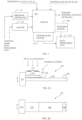
- Figure 1 illustrates an example of manufacture of a ceramic material element 106 for an electrical component.
- the ceramic material element 106 may be made in a mold 100 by forming a mixture of materials A1, A2, A3, A4 and A5, where the material A1 comprises potassium oxide and/or potassium carbon oxide, the material A2 comprises sodium oxide, sodium carbon oxide, potassium oxide and/or potassium carbon oxide, the material A3 comprises barium oxide and/or barium carbon oxide, the material A4 comprises niobium oxide and/or niobium carbon oxide, and the material A5 comprises nickel oxide and/or nickel carbon oxide.
- the materials A1, A2, A3, A4 and A5 have molar ratios R1, R2, R3, R4 and R5, respectively.
- the molar ratio R1 is in a range 0.29-0.32
- the molar ratio R2 is in a range 0.20-0.23
- the molecular ratio R3 is in a range 0.01-0.02
- the molar ratio R4 is in a range 0.54-0.55
- the molar ratio R5 is in a range 0.006-0.011
- a relative ratio of R1/R2 is in the range 1.24-1.52
- a relative ratio of R4/R2 is in the range 2.32-2.
- said mixture is exposed to a heat treatment, which has a temperature within about 700°C to 850°C for a first period. After the first period, the mixture is exposed to a temperature within about 1140°C to 1170°C for a second period in order to form the ceramic material element 106.
- the first period and the second period may be predetermined periods. The first period may last for about one minute to hours, for example. In an embodiment, a duration of the first period is about one minute. The second period may last for about 1 h to 3h, for example.
- the process conditions such as the heat treatment causes formation of aggregates of the materials without particularly inducing chemical reactions. The process conditions namely cause calcination of the materials which results in the formation of the ceramic material element 106.
- the ceramic material element 106 includes a main phase of orthorhombic perovskite-structure and a secondary phase, which, in turn, is a result of the heat treatment and the defined stoichiometry.
- the material of the ceramic material element 106 has a general chemical composition (K x Na y Ba z )(Nb ⁇ Ni ⁇ )O 3- ⁇ (KNBNNO).
- the optimum composition achieved the defined process steps includes both the main phase of the orthorhombic perovskite-structure (K x Na y Ba z )(Nb ⁇ Ni ⁇ )O 3- ⁇ and at least one of the secondary phases of K ⁇ Nb ⁇ O ⁇ , such as tetragonal, cubic or the like.
- the ceramic material element 106 may be made without lead which is an advantage from an environmental point of view.
- the ceramic material element 106 made in this manner is capable of converting both mechanical energy and optical energy to electrical energy.
- the ceramic material element 106 manufactured in this manner may also be capable of converting mechanical energy, thermal energy and optical energy to electrical energy. Pressure is considered be a form of mechanical vibration energy.
- the materials A1, A2, A3, A4 and A5, which exclude lead may be in a form of powder.
- the materials A1, A2, A3, A4 and A5 may be in a wet form allowing a hydrothermal process, a sol-gel process or the like. Also a nanotechnological process may be utilized.
- pressure ranging between about 30 MPa and 60 MPa may be applied to said mixture during the exposure to the first period of the heat treatment.
- the mixture may be formed, in addition to the materials A1, A2, A3, A4 and A5, using at least one of the following additional materials: B1, B2, B3, B4 and B5, where material B1 comprises lithium (Li), material B2 comprises manganese (Mn), material B3 comprises tantalum (Ta), B4 comprises antimony (Sb), and B5 comprises copper (Cu) without limiting to these.
- B1, B2, B3, B4 and B5 where material B1 comprises lithium (Li), material B2 comprises manganese (Mn), material B3 comprises tantalum (Ta), B4 comprises antimony (Sb), and B5 comprises copper (Cu) without limiting to these.
- a person skilled in the art may use also replace any of the additional materials with some other material that he/she finds suitable for the ceramic material element 106.
- a person skilled in the art may use also add some material not mentioned in this list as one of the additional materials if he/she finds such material suitable for the ceramic material element 106.
- the material B1 may comprise lithium oxide and/or lithium carbon oxide
- the material B2 may comprise manganese oxide and/or manganese carbon oxide
- the material B3 may comprise tantalum oxide and/or tantalum carbon oxide
- the material B4 may comprise antimony oxide and/or antimony carbon oxide
- the material B5 may comprise copper oxide and/or copper carbon oxide.
- oxide refers to any degree of oxidation i.e. to any oxidation state.
- the mixture may be formed by mixing the materials B1, B2, B3, B4 and B5 in a powder form with the materials A1, A2, A3, A4 and A5.
- a diameter of particles of the materials B1, B2, B3, B4 and B5 may vary between 50 nm to 5 ⁇ m, for example
- At least one of the materials B1, B2, B3, B4 and B5 may be in a flowable state.
- the mixture may then be formed by mixing the materials B1, B2, B3, B4 and B5 with the materials A1, A2, A3, A4 and A5 in a wet form.
- the material A1 comprises potassium oxide and/or potassium carbon oxide
- the material A2 comprises sodium oxide, sodium carbon oxide, potassium oxide and/or potassium carbon oxide
- the material A3 comprises barium oxide and/or barium carbon oxide
- the material A4 comprises niobium oxide and/or niobium carbon oxide
- the material A5 comprises nickel oxide and/or nickel carbon oxide
- the chemical valence is +1 for A1, +1 for A2, +2 for A3, +5 for A4 and +2 for A5.
- the ceramic material 106 may thus be synthesized from raw reactants of K 2 CO 3 , Na 2 CO 3 , BaCO 3 , Nb 2 O 5 and NiO, for example.
- the mixture may be formed by mixing the materials A1, A2, A3, A4 and A5 in a powder form.
- a diameter of particles of the materials A1, A2, A3, A4 and A5 may vary between about 50 nm to 5 ⁇ m, for example.
- At least one of the materials A1, A2, A3, A4 and A5 may be in a flowable state.
- the mixture may then be formed by mixing the materials A1, A2, A3, A4 and A5 in a wet form.
- the ceramic material element 106 may be formed in form of plate 210.
- the plate 210 may be like a sheet, for example.
- the plate 210 may have electrodes 202, 204 on opposite sides of the element 106.
- At least one of the electrodes 202, 204 may be transparent to the optical radiation that is converted to other energy form or to which some other energy is converted.
- An ITO (Indium Tin Oxide) electrode is transparent, for example, and that may be utilized but the electrodes 202, 204 are not limited to the ITO material.
- Another of the electrodes 202, 204 may be a metal electrode.
- the metal electrode may comprise gold (Au), silver (Ag), copper (Cu), and/or aluminum (Al), for example.
- the ceramic material element 106 may be fabricated via thick-film or thin-film technologies, including but not limited to screen-printing, tape-casting, doctor-blading, sputtering, sol-gel, direct writing, 3D-printing and PLD (Pulsed Laser Deposition).
- thick-film or thin-film technologies including but not limited to screen-printing, tape-casting, doctor-blading, sputtering, sol-gel, direct writing, 3D-printing and PLD (Pulsed Laser Deposition).
- electrodes of the ceramic material element 106 may be fabricated via thick-film or thin-film technologies, including but not limited to screen-printing, tape-casting, doctor-blading, sputtering, sol-gel, direct writing, 3D-printing and PLD (Pulsed Laser Deposition).
- thick-film or thin-film technologies including but not limited to screen-printing, tape-casting, doctor-blading, sputtering, sol-gel, direct writing, 3D-printing and PLD (Pulsed Laser Deposition).
- the ceramic material element 106 may receive and/or output electric energy through the electrodes 202, 204. That is, the ceramic material element 106 may generate an electric potential difference between the electrodes 202, 204, which are attached to the ceramic material element 106 and which do not have a galvanic contact with each other i.e. not short circuited to each other, when the ceramic material element 106 receives mechanical vibrational energy, optical radiation energy and/or thermal energy.
- the electric energy may be detected at the electrodes 202, 204 i.e. the electric energy may carry information.
- the electric energy may be transferred from the electrodes 202, 204 to perform work in some other device.
- the plate 210 of the ceramic material element 106 which has the electrodes 202, 204, may be attached on a beam 206, which is a supportive structure.
- Material of the beam 206 can be freely chosen, and the beam 206 may be made of metal, polymer, glass, ceramic, wood, any combination thereof or the like, for example.
- One end of the beam 106 may be attached to a mechanical vibrational source 212 for converting vibrational energy of the mechanical vibrational source 212 by the element 106 to electric energy.
- the attachment may be temporal or continuous, and the attachment may be done repeatedly to the same mechanical vibration source 212 or to various mechanical vibration sources 212 if the attachment is temporal at least once. Then the electric energy may be output through the electrodes 202, 204 to any receiving device.
- the ceramic material element 106 may cover the entire or only a part of the beam 206.
- the free and non-attached end of the beam 206 may have a tip mass 208 made from any material.
- the tip mass 208 is made of metal, for example.
- the tip mass 208 is made of steel, for example.
- the tip mass 208 is made of lead, for example.
- the tip mass 208 is made of gold, for example.
- the tip mass 208 may have an effect on the frequency band of the vibration such that a desired band of vibration may be converted into electric energy or vice versa.
- the mechanical vibrational source 212 may comprise a wall, a floor, a ceiling, a window or the like of a building.
- the mechanical vibrational source 212 may comprise a bridge, a bike, a motorcycle, a car, a bus, a train, a submarine, a boat, an airplane, a spacecraft or any part of them, for example.
- the mechanical vibrational source 212 may comprise a motor, an engine, or a generator, for example.
- the mechanical vibrational source 212 may comprise a microphone or a loud speaker, for example.
- the mechanical vibrational source 212 may comprise human or animal body movement, geographical movement, or earthquake, for example.
- the unimorph layout shown in the Figures 2A, 2B may alternatively be a bimorph, i.e. two ceramic material elements 106 are attached on both surfaces of the beam 206. In general, there may be a plurality of the ceramic material elements 106 on one or two sides of the beam 206.
- the cantilever may then harvest the vibration energy in a conventional cantilever-structured piezoelectric energy harvesting mode. Alternatively or simultaneously, visible and/or UV (UltraViolet) light as a form of optical radiation may be directed on the top of the component 350 and the ceramic material elements 106, and then be harvested via a photovoltaic effect.
- UV UltraViolet
- the component 350 and the ceramic material elements 106 may be subjected to thermal energy as the heat input, and then the thermal energy may be harvested via a pyroelectric effect. Electric signals may be extracted between the top and bottom electrodes 202, 204. Examples of these signals are illustrated in Figures 6 to 11 . This kind of energy conversion may apply to any embodiment.
- a case 300 which is also a supportive structure, and the plate 210 with the element 106 may be attached together.
- the case 300 is in a physical contact with the plate 210 at or adjacent to a circumference 304 of an area 302 of the plate 210.
- a part of the case 300 is over the area 304 of the plate 210 in a physically contactless manner on a first side 310 of the plate 210.
- the case 300 is in a physical contact with the plate 210 at or adjacent to a circumference 302 of the area 302 of the plate 210. A part of the case 300 is over the area 302 of the plate 210 in a physically contactless manner on a second side 312 of the plate 210.
- the both sided area 302 may thus be within the case 300, or in other words the case 300 may include the area 302 of both sides.
- the case 300 may contain the whole plate 210.
- the case 300 may be transparent to optical radiation on the first side 310 of the plate 210 for receiving and optical radiation and converting energy of the optical radiation to electrical energy.
- the case 300 conducts mechanical vibration to the plate 210 with the element 106 for converting energy of the mechanical vibration to electrical energy.
- the case 300 may be at least partly thermally conductive for allowing the plate 210 with the element 106 receive thermal energy and convert the thermal energy to electrical energy.
- the component 350 is illustrated in Figures 2A to 3B and comprises the ceramic material element 106.
- the ceramic material element 106 is formed, without lead, through the heat treatment as already explained above.
- the ceramic material element 106 is configured to convert optical radiation energy and mechanical vibration energy into electric energy.
- the ceramic material element 106 is additionally configured to convert thermal energy to electric energy.
- the material of the ceramic material element 106 has a general chemical composition (K x Na y Ba z )(Nb ⁇ Ni ⁇ )O 3- ⁇ (KNBNNO).
- the optimum composition achieved the defined process steps includes both the main phase of the orthorhombic perovskite-structure (K x Na y Ba z )(Nb ⁇ Ni ⁇ )O 3- ⁇ and at least one of the secondary phases of K ⁇ Nb ⁇ O ⁇ , such as tetragonal, cubic or the like.
- the component 350 may comprise the plate 210 of the ceramic material element 106, which has electrodes 202, 204 on opposite sides 310, 312 of the element 106.
- the electrodes 202, 204 are configured to conduct electric energy to and/or from the ceramic material element 106.
- a ceramic material element 106 that has electrodes 202, 204 on two sides 310, 312 of the ceramic material element 106 receives mechanical vibrational energy and optical radiation energy.
- the ceramic material element 106 then converts the mechanical vibrational energy and the optical radiation energy to electric energy.
- the ceramic material element 106 finally outputs the electric energy through the electrodes 202, 204, the ceramic material element 106 having both a main phase of orthorhombic perovskite-structure and a secondary phase due to the heat treatment.
- process conditions of the manufacturing process may be measured with at least one sensor 108, 110.
- the processing conditions may also be adjusted by actuators 116, 118, which are controlled by a data processing unit 114.
- the data processing unit 114 may receive information on the temperature in the mould 100 from at least one temperature sensor 110.
- the data processing unit 114 may receive pressure information on the pressure in the mould 100 from at least one pressure sensor 108. Then the data processing unit 114 may control either or both of the heater 118 and the pressure generator 116 such that one or more desired conditions are achieved in the mould 100 for one or more desired periods of time.
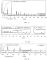
- the X-ray diffraction (XRD) patterns of the ceramic material element 106 which is optimized, and an element manufactured from the same materials according to a prior art method, which is however not optimized in the stoichiometrical manner, are shown in Figures 4A to 4C .
- the properties of the optimized and non-optimized compositions are different.
- the sintered ceramic material of the prior art may be near-transparent with an antique bronze colour, while the ceramic material element 106 is different such that it may be near-opaque with a darker-green (or brown) colour, for example.
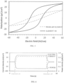
- Figure 5 illustrates an example of ferroelectric hysteresis loops of a prior art ceramic material element and the ceramic material element 106.
- the remanent polarization of the prior art element may only be up to 7 ⁇ C/cm 2 while that of the ceramic material element 106 may be larger than 14 ⁇ C/cm 2 .
- the difference will lead to the piezoelectric coefficient PZC of the prior art element and ceramic material element 106 to be ⁇ 30 pC/N and >80 pC/N, respectively.
- the band gaps GB of the ceramic material may be 1.6 eV or even smaller, while those of the prior art element may be 2.5 eV or even higher.
- the prior art element which is structurally and operationally different from the ceramic material element 106 (see Figures 4A to 5 ) due to a different manufacturing method, is able to simultaneously harvest solar, thermal and kinetic energy via photovoltaic, pyroelectric and piezoelectric effects at least from a theoretical point of view, the conversion efficiency is so low that it is technically and particularly practically unusable. No such a product commercially is available despite the long lasting need.
- the ceramic material element 106 is capable of generating a clearly higher power density than the prior art element, which makes the ceramic material element 106 technically and practically desirable and usable.
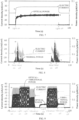
- Figures 6 to 11 illustrate examples of signal input to and output by the ceramic material element 106 when it receives various energy forms.
- the test is based on a component 350 illustrated in Figures 2A, 2B .
- a 1 M ⁇ resistor and a high-precision electrometer (current measurement mode) are connected in series with the top and bottom electrodes 202, 204 of the ceramic material element 106.
- Stainless steel is used as material of the beam 206 with the dimensions of 10 mm x 50 mm x 100 ⁇ m.
- the dimensions of the ceramic material element 106 are 10 mm x 12 mm x 100 ⁇ m, coated with ITO top electrode and silver (Ag; screen-printed, for example) bottom electrode and attached at a fixed side of the cantilever.
- a 1.4 g tip mass 208 which may made from lead (Pb), is attached at the free end of the cantilever.
- the cantilever was mounted on a shaker, which acts as a mechanical vibration source 212, providing the vibration input (12 ⁇ m peak-to-peak amplitude at resonant frequency of the cantilever).
- a 405 nm, 50 mW laser (purple) beam is used as a light source.
- the heat source is provided by a hot air gun.
- Figure 6 illustrates an example of the output current and power densities of a cantilever-structured multi-source energy harvester of Figures 2A and 2B using the ceramic material element 106.
- a value of vibration (kinetic) power is in the vertical axis (left)
- a value of electric current density is in the vertical axis (right)
- time in seconds is in the horizontal axis. It can be seen that the mechanical vibrational power, whose envelope curve is shown in Figure 6 , is converted into electric current, as shown with the curve of an envelope of the electric current density.
- Figure 7 illustrates an example of the output current and power densities of a cantilever-structured multi-source energy harvester of Figures 2A and 2B using the ceramic material element 106.
- the input power is optical radiation.
- a value of the power of the optical radiation is in the vertical axis (left), a value of electric current density is in the vertical axis (right), and time in seconds is in the horizontal axis. It can be seen that the optical radiation power is converted into electric current.
- Figure 8 illustrates an example of the output current and power densities of a cantilever-structured multi-source energy harvester of Figures 2A and 2B using the ceramic material element 106.
- the input power is thermal power.
- a value of the thermal power is in the vertical axis (left)
- a value of electric current density is in the vertical axis (right)
- time in seconds is in the horizontal axis. It can be seen that the thermal power is converted into electric current.
- Figure 9 illustrates an example of the output current and power densities of a cantilever-structured multi-source energy harvester of Figures 2A and 2B using the ceramic material element 106.
- the input powers are vibrational power and optical radiation power.
- a value of the vibrational power and optical radiation power are in the vertical axis (left), a value of electric current density is in the vertical axis (right), and time in seconds is in the horizontal axis. It can be seen that the both the vibrational power and the optical power are simultaneously converted into electric current.
- Figure 10 illustrates an example of the output current and power densities of a cantilever-structured multi-source energy harvester of Figures 2A and 2B using the ceramic material element 106.
- the input powers are optical radiation power and thermal power.
- a value of the optical radiation power and thermal power are in the vertical axis (left), a value of electric current density is in the vertical axis (right), and time in seconds is in the horizontal axis. It can be seen that the both the optical radiation power and the thermal power are simultaneously converted into electric current.
- Figure 11 illustrates an example of the output current and power densities of a cantilever-structured multi-source energy harvester of Figures 2A and 2B using the ceramic material element 106.
- the input powers are vibrational power, optical radiation power and thermal power.
- a value vibrational power, optical radiation power and thermal power are in the vertical axis (left), a value of electric current density is in the vertical axis (right), and time in seconds is in the horizontal axis. It can be seen that the vibrational power, the optical radiation power and the thermal power are simultaneously converted into electric current.
- the same ceramic material element 106 is used in all Figures 6 to 10 .
- Figure 12 is an example of a flow chart of the manufacturing method.
- step 1200 a mixture of materials A1, A2, A3, A4 and A5 excluding lead is formed, the materials A1, A2, A3, A4 and A5 having molar ratios R1, R2, R3, R4 and R5, respectively, where the material A1 comprises potassium oxide and/or potassium carbon oxide, the material A2 comprises sodium oxide, sodium carbon oxide, potassium oxide and/or potassium carbon oxide, the material A3 comprises barium oxide and/or barium carbon oxide, the material A4 comprises niobium oxide and/or niobium carbon oxide, and the material A5 comprises nickel oxide and/or nickel carbon oxide.
- the material A1 comprises potassium oxide and/or potassium carbon oxide
- the material A2 comprises sodium oxide, sodium carbon oxide, potassium oxide and/or potassium carbon oxide
- the material A3 comprises barium oxide and/or barium carbon oxide
- the material A4 comprises niobium oxide and/or niobium carbon oxide
- the material A5 comprises nickel oxide and/or nickel carbon
- step 1202 said mixture is exposed to a heat treatment, which has a temperature within about 700°C to 850°C for a first period, and thereafter a temperature within about 1140°C to 1170°C for a second predefined period in order to form the ceramic material element 106 of the component 350, which converts both mechanical energy and optical energy to electrical energy.
- a heat treatment which has a temperature within about 700°C to 850°C for a first period, and thereafter a temperature within about 1140°C to 1170°C for a second predefined period in order to form the ceramic material element 106 of the component 350, which converts both mechanical energy and optical energy to electrical energy.
- the molar ratio R1 may be in a range about 0.29-0.32
- the molar ratio R2 may be in a range about 0.20-0.23
- the molecular ratio R3 may be in a range about 0.01-0.02
- the molar ratio R4 may be in a range about 0.54-0.55
- the molar ratio R5 may be in a range about 0.006-0.011.
- the relative ratio of R1/R2 should be in the range about 1.24-1.52
- the relative ratio of R4/R2 should be in the range about 2.32-2.62.
- Figure 13 is an example of a flow chart of the energy conversion method.
- mechanical vibrational energy and optical radiation energy is received by a ceramic material element 106 that has electrodes 202, 204 on two sides of the ceramic material element 106. Also thermal energy may be received.
- the mechanical vibrational energy and the optical radiation energy are converted by the ceramic material element 106 to electric energy. Also thermal energy may be converted into electric energy.
- the single ceramic material element 106 which is made from only one energy conversion material, is capable of simultaneously converting a plurality of energy forms visible optical radiation, heat, kinetic energy and electricity to at least one energy form. For energy harvesting, optical radiation, heat, kinetic energy can efficiently be converted into electricity.
- the configurations of conventional multi-source energy converters made from different energy conversion materials can thus be replaced by a component utilizing this simple ceramic material element 106. Because no further simplification beyond this can be made on the structure of the energy conversion component in a multi-source energy converter, the cost, design and engineering of multi-source energy converters may be significantly reduced and simplified with this solution.
- the applications of this new material may cover the fields of sensing, energy harvesting and optoelectronics, for example.
- This material has the chemical composition of (K x Na y Ba z )(Nb ⁇ Ni ⁇ )O 3- ⁇ (KNBNNO).
- KNBNNO K x Na y Ba z )(Nb ⁇ Ni ⁇ )O 3- ⁇
- a proper or optimized stoichiometry is needed to optimize the comprehensive properties of the material, which has been described in this document. With the optimum composition, the material may be made to absorb the entire visible and UV range of the solar spectrum.
- RM remanent polarization
- PEC piezoelectric PZC and pyroelectric coefficients
- PEC piezoelectric coefficients
- PEC piezoelectric coefficients
- BG band gap
- the fabricated energy harvesters may convert visible and/or UV light, temperature fluctuation and kinetic energy (e.g.
- the design of the multi-source energy harvesters using only one energy conversion material may become versatile and universal.
- the relatively complex conventional designs where different energy conversion materials for harvesting different energy sources are compulsory may not be necessary any more.
- the energy conversion material in this invention is lead-free, which avoids the use of toxic and hazardous PZT or other lead-based piezoelectric materials of the conventional kinetic energy harvesters.
- CMOS Complementary Metal Oxide Semiconductor
- MEMS Micro-ElectroMechanical Systems
Landscapes
- Chemical & Material Sciences (AREA)
- Engineering & Computer Science (AREA)
- Ceramic Engineering (AREA)
- Manufacturing & Machinery (AREA)
- Materials Engineering (AREA)
- Structural Engineering (AREA)
- Organic Chemistry (AREA)
- Inorganic Chemistry (AREA)
- Compositions Of Oxide Ceramics (AREA)
Claims (13)
- Verfahren zur Herstellung eines elektrokeramischen Verbundbauteils, gekennzeichnet durch:Bilden (1200) einer Mischung aus den Materialien A1, A2, A3, A4 und A5 ohne Blei, wobei die Materialien A1, A2, A3, A4 und A5 die Molverhältnisse R1, R2, R3, R4 bzw. R5 aufweisen, wobei das Material A1 Kaliumoxid und/oder Kaliumkohlenoxid umfasst, das Material A2 Natriumoxid, Natriumkohlenoxid, Kaliumoxid und/oder Kaliumkohlenoxid umfasst, das Material A3 Bariumoxid und/oder Bariumkohlenoxid umfasst, das Material A4 Nioboxid und/oder Niobkohlenoxid umfasst und das Material A5 Nickeloxid und/oder Nickelkohlenoxid umfasst; undAussetzen (1202) der Mischung einer Wärmebehandlung bei einer Temperatur zwischen 700°C und 850°C für einen ersten Zeitraum und danach bei einer Temperatur zwischen 1140°C und 1170°C für einen zweiten vordefinierten Zeitraum, um das Element aus keramischem Material (106) des Bauteils (350) zu bilden, mit dem Molverhältnis R1 in einem Bereich von etwa 0,29-0,32, dem Molverhältnis R2 in einem Bereich von etwa 0,20-0,23, dem Molverhältnis R3 in einem Bereich von etwa 0,01-0,02, dem Molverhältnis R4 in einem Bereich von etwa 0,54-0,55 und dem Molverhältnis R5 in einem Bereich von etwa 0,006-0,011, während das relative Verhältnis von R1/R2 im Bereich von etwa 1,24-1,52 liegt und das relative Verhältnis von R4/R2 im Bereich von etwa 2,32-2,62 liegt, für die Umwandlung von mechanischer Energie und optischer Energie in elektrische Energie, um Material mit der chemischen Zusammensetzung (KxNayBaz) (NbαNiβ) O3-δ-Oxid-Perowskit-Keramik herzustellen.
- Verfahren nach Anspruch 1, gekennzeichnet durch das Anwenden von Druck von 30 MPa bis 60 MPa auf die Mischung.
- Verfahren nach Anspruch 1, gekennzeichnet durch das Bilden der Mischung zusätzlich zu den Materialien A1, A2, A3, A4 und A5 mit mindestens einem der folgenden Materialien: B1, B2, B3, B4 und B5, wobei das Material B1 Lithium (Li) umfasst, das Material B2 Mangan (Mn) umfasst, das Material B3 Tantal (Ta) umfasst, B4 Antimon (Sb) umfasst und B5 Kupfer (Cu) umfasst; und wobei das Material B1 Lithiumoxid und/oder Lithiumkohlenoxid umfasst, das Material B2 Manganoxid und/oder Mangankohlenoxid umfasst, das Material B3 Tantaloxid und/oder Tantalkohlenoxid umfasst, das Material B4 Antimonoxid und/oder Antimonkohlenoxid umfasst und das Material B5 Kupferoxid und/oder Kupferkohlenoxid umfasst.
- Verfahren nach Anspruch 3, gekennzeichnet durch das Bilden der Mischung durch Mischen der Materialien B1, B2, B3, B4 und B5 in Pulverform mit den Materialien A1, A2, A3, A4 und A5.
- Verfahren nach Anspruch 3, dadurch gekennzeichnet, dass sich mindestens eines der Materialien B1, B2, B3, B4 und B5 in einem fließfähigen Zustand befindet, und die Mischung durch das Mischen der Materialien B1, B2, B3, B4 und B5 mit den Materialien A1, A2, A3, A4 und A5 in nasser Form gebildet wird.
- Verfahren nach Anspruch 1, gekennzeichnet durch das Bilden der Mischung durch Mischen der Materialien A1, A2, A3, A4 und A5 in Pulverform.
- Verfahren nach Anspruch 1, dadurch gekennzeichnet, dass sich mindestens eines der Materialien A1, A2, A3, A4 und A5 in einem fließfähigen Zustand befindet, und die Mischung durch das Mischen der Materialien A1, A2, A3, A4 und A5 in nasser Form gebildet wird.
- Verfahren nach Anspruch 1, gekennzeichnet durch:
Bilden einer Platte (210) mit dem Element aus keramischem Material (106) und den Elektroden (202, 204) durch Bilden von Elektroden (202, 204) auf gegenüberliegenden Seiten (310, 312) des Elements aus keramischem Material (106), wobei das Element aus keramischem Material (106) elektrische Energie durch die Elektroden (202, 204) aufnimmt und/oder abgibt. - Verfahren nach Anspruch 8, gekennzeichnet durch das Befestigen der Platte (210) mit dem Element aus keramischem Material (106) und den Elektroden (202, 204) auf einem Träger (206), wobei ein Ende des Trägers (206) so konfiguriert ist, dass es an einer mechanischen Schwingungsquelle (212) befestigt wird, zum Umwandeln von Schwingungsenergie der mechanischen Schwingungsquelle (212) durch das Element aus keramischem Material (106) in elektrische Energie, damit die elektrische Energie über die Elektroden (202, 204) abgegeben werden kann.
- Verfahren nach Anspruch 8, gekennzeichnet durch das Befestigen eines Gehäuses (300) an der Platte (210) mit dem Element aus keramischem Material (106), so dass sich das Gehäuse (300) in einem physischen Kontakt mit der Platte (210) an oder benachbart zu einem Umfang (304) eines Bereichs (302) der Platte (210) befindet, und sich das Gehäuse (300) auf einer ersten Seite (310) der Platte (210) physisch berührungslos über dem Bereich (302) der Platte (210) befindet;wobei sich das Gehäuse (300) an einem Umfang (304) des Bereichs (302) der Platte (210) in physischem Kontakt mit der Platte (210) befindet, und sich das Gehäuse (300) auf einer zweiten Seite (312) der Platte (210) physisch berührungslos über dem Bereich (302) der Platte (210) befindet, um den Bereich (302) der Platte (210) innerhalb des Gehäuses (300) zu haben;wobei das Gehäuse (300) auf der ersten Seite der Platte (210) für optische Strahlung durchlässig ist, um die Energie der optischen Strahlung in elektrische Energie umzuwandeln;wobei das Gehäuse (300) mechanische Schwingungen zu der Platte (210) mit dem Element aus keramischem Material (106) leitet, um die Energie der mechanischen Schwingungen in elektrische Energie umzuwandeln;wobei das Gehäuse (300) zumindest teilweise wärmeleitend ist, damit die Platte (210) mit dem Element aus keramischem Material (106) thermische Energie aufnehmen und die thermische Energie in elektrische Energie umzuwandeln kann.
- Bauteil (350) mit einem Element aus keramischem Material (106), dadurch gekennzeichnet, dassdas Element aus keramischem Material (106) eine Hauptphase mit orthorhombischer Perowskit-Struktur und eine Sekundärphase aufgrund einer Wärmebehandlung bei 700°C bis 850°C für einen ersten Zeitraum, gefolgt von einem zweiten Zeitraum bei 1140°C bis 1170°C, aus einer Mischung der Materialien A1, A2, A3, A4 und A5 ohne Blei umfasst, wobei die Materialien A1, A2, A3, A4 und A5 die Molverhältnisse R1, R2, R3, R4 bzw. R5 aufweisen, wobei das Material A1 Kalium umfasst, das Material A2 Natrium umfasst, das Material A3 Barium umfasst, das Material A4 Niob umfasst und das Material A5 Nickel umfasst und das Molverhältnis R1 in einem Bereich von 0,29-0,32 liegt, das Molverhältnis R2 in einem Bereich von 0,20-0,23 liegt, das Molverhältnis R3 in einem Bereich von 0,01-0,02 liegt, das Molverhältnis R4 in einem Bereich von 0,54-0,55 liegt und das Molverhältnis R5 in einem Bereich von 0,006-0,011 liegt, während ein relatives Verhältnis von R1/R2 im Bereich von 1,24-1,52 und ein relatives Verhältnis von R4/R2 im Bereich von 2,32-2,62 liegt, wobei das keramische Material die chemische Zusammensetzung (KxNayBaz)(NbαNiβ)O3-δ-Oxid-Perowskit-Keramik aufweist; unddas Element aus keramischem Material (106) so konfiguriert ist, dass es optische Strahlungsenergie und mechanische Schwingungsenergie in elektrische Energie umwandelt.
- Bauteil (350) nach Anspruch 11, dadurch gekennzeichnet, dass das Bauteil (350) Folgendes umfasst:eine Platte (210) mit dem Element aus keramischem Material (106), die so konfiguriert ist, dass sie Elektroden (202, 204) auf gegenüberliegenden Seiten (310, 312) des Elements aus keramischem Material (106) aufweist; undElektroden (202, 204), die so konfiguriert sind, dass sie elektrische Energie zu dem Element aus keramischem Material (106) leiten und/oder von ihm ableiten.
- Verfahren zum Umwandeln von Energie, gekennzeichnet durch:Aufnehmen (1300) von mechanischer Schwingungsenergie und optischer Strahlungsenergie durch ein Element aus keramischem Material (106), das Elektroden (202, 204) auf zwei Seiten des Elements aus keramischem Material (106) aufweist;Umwandeln (1302) der mechanischen Schwingungsenergie und der optischen Strahlungsenergie in elektrische Energie durch das Element aus keramischem Material (106); undAbgeben (1304) der elektrischen Energie durch die Elektroden (202, 204), wobei das Element aus keramischem Material (106) eine Hauptphase mit orthorhombischer Perowskit-Struktur und eine Sekundärphase umfasst, die durch eine Wärmebehandlung bei 700°C bis 850°C für einen ersten Zeitraum, gefolgt von einem zweiten Zeitraum bei 1140°C bis 1170°C gebildet wird, aus einer Mischung der Materialien A1, A2, A3, A4 und A5 ohne Blei, wobei die Materialien A1, A2, A3, A4 und A5 die Molverhältnisse R1, R2, R3, R4 bzw. R5 aufweisen, wobei das Material A1 Kalium umfasst, das Material A2 Natrium umfasst, das Material A3 Barium umfasst, das Material A4 Niob umfasst und das Material A5 Nickel umfasst, und das Molverhältnis R1 in einem Bereich von 0,29-0,32 liegt, das Molverhältnis R2 in einem Bereich von 0,20-0,23 liegt, das Molverhältnis R3 in einem Bereich von 0,01-0,02 liegt, das Molverhältnis R4 in einem Bereich von 0,54-0,55 liegt und das Molverhältnis R5 in einem Bereich von 0,006-0,011 liegt, während ein relatives Verhältnis von R1/R2 im Bereich von 1,24-1,52 liegt und ein relatives Verhältnis von R4/R2 im Bereich 2,32-2,62 liegt.
Applications Claiming Priority (2)
| Application Number | Priority Date | Filing Date | Title |
|---|---|---|---|
| FI20196042 | 2019-12-02 | ||
| PCT/FI2020/050810 WO2021111035A1 (en) | 2019-12-02 | 2020-12-01 | Electro-ceramic material component, its manufacturing method and method of converting energy |
Publications (4)
| Publication Number | Publication Date |
|---|---|
| EP4069658A1 EP4069658A1 (de) | 2022-10-12 |
| EP4069658A4 EP4069658A4 (de) | 2024-01-31 |
| EP4069658B1 true EP4069658B1 (de) | 2025-02-26 |
| EP4069658C0 EP4069658C0 (de) | 2025-02-26 |
Family
ID=76222315
Family Applications (1)
| Application Number | Title | Priority Date | Filing Date |
|---|---|---|---|
| EP20896253.0A Active EP4069658B1 (de) | 2019-12-02 | 2020-12-01 | Elektrokeramisches bauteil, sein herstellungsverfahren und verfahren zur energieumwandlung |
Country Status (4)
| Country | Link |
|---|---|
| US (1) | US11613503B2 (de) |
| EP (1) | EP4069658B1 (de) |
| GB (1) | GB2593105B (de) |
| WO (1) | WO2021111035A1 (de) |
Family Cites Families (8)
| Publication number | Priority date | Publication date | Assignee | Title |
|---|---|---|---|---|
| TW560094B (en) | 2001-06-15 | 2003-11-01 | Tdk Corp | Piezoelectric ceramic and method of manufacturing |
| US7101491B2 (en) * | 2002-07-16 | 2006-09-05 | Denso Corporation | Piezoelectric ceramic composition and method of production of same, piezoelectric element, and dielectric element |
| US9484475B2 (en) * | 2011-10-11 | 2016-11-01 | The Trustees Of The University Of Pennsylvania | Semiconductor ferroelectric compositions and their use in photovoltaic devices |
| JP5823014B2 (ja) | 2014-04-11 | 2015-11-25 | 日本特殊陶業株式会社 | 無鉛圧電磁器組成物、それを用いた圧電素子、及び、無鉛圧電磁器組成物の製造方法 |
| EP3268996B1 (de) * | 2015-04-03 | 2019-12-11 | C/o Canon Kabushiki Kaisha | Piezoelektrisches material, verfahren zur herstellung des piezoelektrischen materials, piezoelektrisches element und elektronische vorrichtung |
| US20170330983A1 (en) * | 2015-12-07 | 2017-11-16 | Peter K. Davies | Ferroelectric Perovskite Oxide-Based Photovoltaic Materials |
| US10749056B2 (en) * | 2016-02-11 | 2020-08-18 | Drexel University | Method for making ferroelectric material thin films |
| JP2020500138A (ja) * | 2016-10-31 | 2020-01-09 | クエスト インテグレーテッド, エルエルシー | 単結晶のエピタキシャル成長のための、均衡点を有する単結晶ペロブスカイト固溶体 |
-
2020
- 2020-12-01 EP EP20896253.0A patent/EP4069658B1/de active Active
- 2020-12-01 WO PCT/FI2020/050810 patent/WO2021111035A1/en not_active Ceased
- 2020-12-01 GB GB2108204.5A patent/GB2593105B/en active Active
- 2020-12-01 US US17/633,322 patent/US11613503B2/en active Active
Also Published As
| Publication number | Publication date |
|---|---|
| WO2021111035A1 (en) | 2021-06-10 |
| GB202108204D0 (en) | 2021-07-21 |
| GB2593105B (en) | 2022-03-09 |
| US11613503B2 (en) | 2023-03-28 |
| EP4069658C0 (de) | 2025-02-26 |
| GB2593105A (en) | 2021-09-15 |
| US20220267219A1 (en) | 2022-08-25 |
| EP4069658A4 (de) | 2024-01-31 |
| EP4069658A1 (de) | 2022-10-12 |
Similar Documents
| Publication | Publication Date | Title |
|---|---|---|
| Sekhar et al. | A review on piezoelectric materials and their applications | |
| Alluri et al. | Flexible, hybrid piezoelectric film (BaTi (1–x) Zr x O3)/PVDF nanogenerator as a self-powered fluid velocity sensor | |
| Chen et al. | A flexible PMN‐PT ribbon‐based piezoelectric‐pyroelectric hybrid generator for human‐activity energy harvesting and monitoring | |
| Alluri et al. | Exalted electric output via piezoelectric–triboelectric coupling/sustainable butterfly wing structure type multiunit hybrid nanogenerator | |
| Jayakrishnan et al. | Inorganic ferroelectric thin films and their composites for flexible electronic and energy device applications: current progress and perspectives | |
| Raj et al. | Sustainable yarn type-piezoelectric energy harvester as an eco-friendly, cost-effective battery-free breath sensor | |
| Sitharthan et al. | Analysis on smart material suitable for autogenous microelectronic application | |
| Oh et al. | Development of a tree‐shaped wind power system using piezoelectric materials | |
| Panda et al. | Pyroelectric based energy harvesting devices: hybrid structures and applications | |
| KR101449746B1 (ko) | 압전 소자층을 포함하는 하이브리드 태양전지 및 이의 제조방법 | |
| Bhatnagar et al. | Piezoelectric energy harvesting: from fundamentals to advanced applications | |
| JP4156461B2 (ja) | 圧電磁器組成物及びその製造方法並びに圧電素子 | |
| EP4069658B1 (de) | Elektrokeramisches bauteil, sein herstellungsverfahren und verfahren zur energieumwandlung | |
| KR102052907B1 (ko) | 하이브리드 방식의 전력발전소자 및 이의 제조방법 | |
| Lee et al. | Relationship between piezoelectric properties of ceramics and output performance of 33-mode piezoelectric energy harvesters | |
| Lee et al. | Accelerate the shift to green energy with PVDF based piezoelectric nanogenerator | |
| Meng et al. | Built-in piezoelectric nanogenerators promote sustainable and flexible supercapacitors: a review | |
| Li et al. | High-performance low-frequency MEMS energy harvester via partially covering PZT thick film | |
| WO2018195383A1 (en) | Two-dimensional material with electroactivity and photosensitivity | |
| Sreeja et al. | Piezoelectric energy harvesting system suitable for remotely placed sensors with inter-digitated design | |
| US20070087930A1 (en) | High energy density piezoelectric ceramic materials | |
| Praveenkumar et al. | Design optimization and simulation of micro-electro-mechanical system based solar energy harvester for low voltage applications | |
| Rajagopalan et al. | Elucidations on the effect of lanthanum doping in ZnO towards enhanced performance nanogenerators | |
| JP2011233630A (ja) | 発電部材およびこれを用いた発電装置 | |
| JP2006093385A (ja) | 光電変換構造体及びその製造方法 |
Legal Events
| Date | Code | Title | Description |
|---|---|---|---|
| STAA | Information on the status of an ep patent application or granted ep patent |
Free format text: STATUS: THE INTERNATIONAL PUBLICATION HAS BEEN MADE |
|
| PUAI | Public reference made under article 153(3) epc to a published international application that has entered the european phase |
Free format text: ORIGINAL CODE: 0009012 |
|
| STAA | Information on the status of an ep patent application or granted ep patent |
Free format text: STATUS: REQUEST FOR EXAMINATION WAS MADE |
|
| 17P | Request for examination filed |
Effective date: 20220617 |
|
| AK | Designated contracting states |
Kind code of ref document: A1 Designated state(s): AL AT BE BG CH CY CZ DE DK EE ES FI FR GB GR HR HU IE IS IT LI LT LU LV MC MK MT NL NO PL PT RO RS SE SI SK SM TR |
|
| DAV | Request for validation of the european patent (deleted) | ||
| DAX | Request for extension of the european patent (deleted) | ||
| A4 | Supplementary search report drawn up and despatched |
Effective date: 20240105 |
|
| RIC1 | Information provided on ipc code assigned before grant |
Ipc: H01L 31/0264 20060101ALI20231222BHEP Ipc: C04B 35/495 20060101ALI20231222BHEP Ipc: C04B 35/64 20060101AFI20231222BHEP |
|
| GRAP | Despatch of communication of intention to grant a patent |
Free format text: ORIGINAL CODE: EPIDOSNIGR1 |
|
| STAA | Information on the status of an ep patent application or granted ep patent |
Free format text: STATUS: GRANT OF PATENT IS INTENDED |
|
| INTG | Intention to grant announced |
Effective date: 20240926 |
|
| GRAS | Grant fee paid |
Free format text: ORIGINAL CODE: EPIDOSNIGR3 |
|
| GRAA | (expected) grant |
Free format text: ORIGINAL CODE: 0009210 |
|
| STAA | Information on the status of an ep patent application or granted ep patent |
Free format text: STATUS: THE PATENT HAS BEEN GRANTED |
|
| RBV | Designated contracting states (corrected) |
Designated state(s): AL AT BE BG CH CY CZ DE DK EE ES FI FR GR HR HU IE IS IT LI LT LU LV MC MK MT NL NO PL PT RO RS SE SI SK SM TR |
|
| AK | Designated contracting states |
Kind code of ref document: B1 Designated state(s): AL AT BE BG CH CY CZ DE DK EE ES FI FR GR HR HU IE IS IT LI LT LU LV MC MK MT NL NO PL PT RO RS SE SI SK SM TR |
|
| REG | Reference to a national code |
Ref country code: CH Ref legal event code: EP |
|
| REG | Reference to a national code |
Ref country code: DE Ref legal event code: R096 Ref document number: 602020046997 Country of ref document: DE |
|
| REG | Reference to a national code |
Ref country code: IE Ref legal event code: FG4D |
|
| U01 | Request for unitary effect filed |
Effective date: 20250313 |
|
| U07 | Unitary effect registered |
Designated state(s): AT BE BG DE DK EE FI FR IT LT LU LV MT NL PT RO SE SI Effective date: 20250324 |
|
| PG25 | Lapsed in a contracting state [announced via postgrant information from national office to epo] |
Ref country code: RS Free format text: LAPSE BECAUSE OF FAILURE TO SUBMIT A TRANSLATION OF THE DESCRIPTION OR TO PAY THE FEE WITHIN THE PRESCRIBED TIME-LIMIT Effective date: 20250526 |
|
| PG25 | Lapsed in a contracting state [announced via postgrant information from national office to epo] |
Ref country code: PL Free format text: LAPSE BECAUSE OF FAILURE TO SUBMIT A TRANSLATION OF THE DESCRIPTION OR TO PAY THE FEE WITHIN THE PRESCRIBED TIME-LIMIT Effective date: 20250226 |
|
| PG25 | Lapsed in a contracting state [announced via postgrant information from national office to epo] |
Ref country code: ES Free format text: LAPSE BECAUSE OF FAILURE TO SUBMIT A TRANSLATION OF THE DESCRIPTION OR TO PAY THE FEE WITHIN THE PRESCRIBED TIME-LIMIT Effective date: 20250226 |
|
| PG25 | Lapsed in a contracting state [announced via postgrant information from national office to epo] |
Ref country code: NO Free format text: LAPSE BECAUSE OF FAILURE TO SUBMIT A TRANSLATION OF THE DESCRIPTION OR TO PAY THE FEE WITHIN THE PRESCRIBED TIME-LIMIT Effective date: 20250526 Ref country code: IS Free format text: LAPSE BECAUSE OF FAILURE TO SUBMIT A TRANSLATION OF THE DESCRIPTION OR TO PAY THE FEE WITHIN THE PRESCRIBED TIME-LIMIT Effective date: 20250626 |
|
| PG25 | Lapsed in a contracting state [announced via postgrant information from national office to epo] |
Ref country code: HR Free format text: LAPSE BECAUSE OF FAILURE TO SUBMIT A TRANSLATION OF THE DESCRIPTION OR TO PAY THE FEE WITHIN THE PRESCRIBED TIME-LIMIT Effective date: 20250226 |
|
| PG25 | Lapsed in a contracting state [announced via postgrant information from national office to epo] |
Ref country code: GR Free format text: LAPSE BECAUSE OF FAILURE TO SUBMIT A TRANSLATION OF THE DESCRIPTION OR TO PAY THE FEE WITHIN THE PRESCRIBED TIME-LIMIT Effective date: 20250527 |
|
| PG25 | Lapsed in a contracting state [announced via postgrant information from national office to epo] |
Ref country code: SM Free format text: LAPSE BECAUSE OF FAILURE TO SUBMIT A TRANSLATION OF THE DESCRIPTION OR TO PAY THE FEE WITHIN THE PRESCRIBED TIME-LIMIT Effective date: 20250226 |
|
| PG25 | Lapsed in a contracting state [announced via postgrant information from national office to epo] |
Ref country code: CZ Free format text: LAPSE BECAUSE OF FAILURE TO SUBMIT A TRANSLATION OF THE DESCRIPTION OR TO PAY THE FEE WITHIN THE PRESCRIBED TIME-LIMIT Effective date: 20250226 |
|
| PG25 | Lapsed in a contracting state [announced via postgrant information from national office to epo] |
Ref country code: SK Free format text: LAPSE BECAUSE OF FAILURE TO SUBMIT A TRANSLATION OF THE DESCRIPTION OR TO PAY THE FEE WITHIN THE PRESCRIBED TIME-LIMIT Effective date: 20250226 |
|
| PLBE | No opposition filed within time limit |
Free format text: ORIGINAL CODE: 0009261 |
|
| REG | Reference to a national code |
Ref country code: CH Ref legal event code: U11 Free format text: ST27 STATUS EVENT CODE: U-0-0-U10-U11 (AS PROVIDED BY THE NATIONAL OFFICE) Effective date: 20260101 |
|
| STAA | Information on the status of an ep patent application or granted ep patent |
Free format text: STATUS: NO OPPOSITION FILED WITHIN TIME LIMIT |
|
| PGFP | Annual fee paid to national office [announced via postgrant information from national office to epo] |
Ref country code: IE Payment date: 20251219 Year of fee payment: 6 |
|
| 26N | No opposition filed |
Effective date: 20251127 |
|
| U20 | Renewal fee for the european patent with unitary effect paid |
Year of fee payment: 6 Effective date: 20251230 |