EP4068568B1 - System und verfahren zur versorgung eines beweglichen elements auf einem förderband mit energie und durch die versorgung eines beweglichen elements mit energie angetriebenes zubehör - Google Patents
System und verfahren zur versorgung eines beweglichen elements auf einem förderband mit energie und durch die versorgung eines beweglichen elements mit energie angetriebenes zubehör Download PDFInfo
- Publication number
- EP4068568B1 EP4068568B1 EP22165810.7A EP22165810A EP4068568B1 EP 4068568 B1 EP4068568 B1 EP 4068568B1 EP 22165810 A EP22165810 A EP 22165810A EP 4068568 B1 EP4068568 B1 EP 4068568B1
- Authority
- EP
- European Patent Office
- Prior art keywords
- accessory
- moving element
- power
- gripper
- moving
- Prior art date
- Legal status (The legal status is an assumption and is not a legal conclusion. Google has not performed a legal analysis and makes no representation as to the accuracy of the status listed.)
- Active
Links
Images


Classifications
-
- B—PERFORMING OPERATIONS; TRANSPORTING
- B65—CONVEYING; PACKING; STORING; HANDLING THIN OR FILAMENTARY MATERIAL
- B65G—TRANSPORT OR STORAGE DEVICES, e.g. CONVEYORS FOR LOADING OR TIPPING, SHOP CONVEYOR SYSTEMS OR PNEUMATIC TUBE CONVEYORS
- B65G43/00—Control devices, e.g. for safety, warning or fault-correcting
- B65G43/08—Control devices operated by article or material being fed, conveyed or discharged
-
- H—ELECTRICITY
- H02—GENERATION; CONVERSION OR DISTRIBUTION OF ELECTRIC POWER
- H02J—CIRCUIT ARRANGEMENTS OR SYSTEMS FOR SUPPLYING OR DISTRIBUTING ELECTRIC POWER; SYSTEMS FOR STORING ELECTRIC ENERGY
- H02J50/00—Circuit arrangements or systems for wireless supply or distribution of electric power
- H02J50/005—Mechanical details of housing or structure aiming to accommodate the power transfer means, e.g. mechanical integration of coils, antennas or transducers into emitting or receiving devices
-
- B—PERFORMING OPERATIONS; TRANSPORTING
- B65—CONVEYING; PACKING; STORING; HANDLING THIN OR FILAMENTARY MATERIAL
- B65G—TRANSPORT OR STORAGE DEVICES, e.g. CONVEYORS FOR LOADING OR TIPPING, SHOP CONVEYOR SYSTEMS OR PNEUMATIC TUBE CONVEYORS
- B65G47/00—Article or material-handling devices associated with conveyors; Methods employing such devices
- B65G47/74—Feeding, transfer, or discharging devices of particular kinds or types
- B65G47/90—Devices for picking-up and depositing articles or materials
- B65G47/905—Control arrangements
-
- B—PERFORMING OPERATIONS; TRANSPORTING
- B65—CONVEYING; PACKING; STORING; HANDLING THIN OR FILAMENTARY MATERIAL
- B65G—TRANSPORT OR STORAGE DEVICES, e.g. CONVEYORS FOR LOADING OR TIPPING, SHOP CONVEYOR SYSTEMS OR PNEUMATIC TUBE CONVEYORS
- B65G47/00—Article or material-handling devices associated with conveyors; Methods employing such devices
- B65G47/74—Feeding, transfer, or discharging devices of particular kinds or types
- B65G47/90—Devices for picking-up and depositing articles or materials
- B65G47/91—Devices for picking-up and depositing articles or materials incorporating pneumatic, e.g. suction, grippers
- B65G47/914—Devices for picking-up and depositing articles or materials incorporating pneumatic, e.g. suction, grippers provided with drive systems incorporating rotary and rectilinear movements
-
- H—ELECTRICITY
- H02—GENERATION; CONVERSION OR DISTRIBUTION OF ELECTRIC POWER
- H02J—CIRCUIT ARRANGEMENTS OR SYSTEMS FOR SUPPLYING OR DISTRIBUTING ELECTRIC POWER; SYSTEMS FOR STORING ELECTRIC ENERGY
- H02J50/00—Circuit arrangements or systems for wireless supply or distribution of electric power
- H02J50/10—Circuit arrangements or systems for wireless supply or distribution of electric power using inductive coupling
-
- H—ELECTRICITY
- H02—GENERATION; CONVERSION OR DISTRIBUTION OF ELECTRIC POWER
- H02J—CIRCUIT ARRANGEMENTS OR SYSTEMS FOR SUPPLYING OR DISTRIBUTING ELECTRIC POWER; SYSTEMS FOR STORING ELECTRIC ENERGY
- H02J50/00—Circuit arrangements or systems for wireless supply or distribution of electric power
- H02J50/80—Circuit arrangements or systems for wireless supply or distribution of electric power involving the exchange of data, concerning supply or distribution of electric power, between transmitting devices and receiving devices
-
- H—ELECTRICITY
- H04—ELECTRIC COMMUNICATION TECHNIQUE
- H04L—TRANSMISSION OF DIGITAL INFORMATION, e.g. TELEGRAPHIC COMMUNICATION
- H04L67/00—Network arrangements or protocols for supporting network services or applications
- H04L67/01—Protocols
- H04L67/12—Protocols specially adapted for proprietary or special-purpose networking environments, e.g. medical networks, sensor networks, networks in vehicles or remote metering networks
-
- H—ELECTRICITY
- H04—ELECTRIC COMMUNICATION TECHNIQUE
- H04W—WIRELESS COMMUNICATION NETWORKS
- H04W4/00—Services specially adapted for wireless communication networks; Facilities therefor
- H04W4/30—Services specially adapted for particular environments, situations or purposes
- H04W4/33—Services specially adapted for particular environments, situations or purposes for indoor environments, e.g. buildings
-
- H—ELECTRICITY
- H04—ELECTRIC COMMUNICATION TECHNIQUE
- H04W—WIRELESS COMMUNICATION NETWORKS
- H04W4/00—Services specially adapted for wireless communication networks; Facilities therefor
- H04W4/50—Service provisioning or reconfiguring
-
- H—ELECTRICITY
- H04—ELECTRIC COMMUNICATION TECHNIQUE
- H04W—WIRELESS COMMUNICATION NETWORKS
- H04W4/00—Services specially adapted for wireless communication networks; Facilities therefor
- H04W4/70—Services for machine-to-machine communication [M2M] or machine type communication [MTC]
-
- H—ELECTRICITY
- H05—ELECTRIC TECHNIQUES NOT OTHERWISE PROVIDED FOR
- H05B—ELECTRIC HEATING; ELECTRIC LIGHT SOURCES NOT OTHERWISE PROVIDED FOR; CIRCUIT ARRANGEMENTS FOR ELECTRIC LIGHT SOURCES, IN GENERAL
- H05B1/00—Details of electric heating devices
- H05B1/02—Automatic switching arrangements specially adapted to apparatus ; Control of heating devices
- H05B1/0227—Applications
- H05B1/023—Industrial applications
-
- B—PERFORMING OPERATIONS; TRANSPORTING
- B65—CONVEYING; PACKING; STORING; HANDLING THIN OR FILAMENTARY MATERIAL
- B65G—TRANSPORT OR STORAGE DEVICES, e.g. CONVEYORS FOR LOADING OR TIPPING, SHOP CONVEYOR SYSTEMS OR PNEUMATIC TUBE CONVEYORS
- B65G2203/00—Indexing code relating to control or detection of the articles or the load carriers during conveying
- B65G2203/02—Control or detection
- B65G2203/0208—Control or detection relating to the transported articles
- B65G2203/0258—Weight of the article
-
- F—MECHANICAL ENGINEERING; LIGHTING; HEATING; WEAPONS; BLASTING
- F25—REFRIGERATION OR COOLING; COMBINED HEATING AND REFRIGERATION SYSTEMS; HEAT PUMP SYSTEMS; MANUFACTURE OR STORAGE OF ICE; LIQUEFACTION SOLIDIFICATION OF GASES
- F25B—REFRIGERATION MACHINES, PLANTS OR SYSTEMS; COMBINED HEATING AND REFRIGERATION SYSTEMS; HEAT PUMP SYSTEMS
- F25B21/00—Machines, plants or systems, using electric or magnetic effects
- F25B21/02—Machines, plants or systems, using electric or magnetic effects using Peltier effect; using Nernst-Ettinghausen effect
-
- G—PHYSICS
- G01—MEASURING; TESTING
- G01L—MEASURING FORCE, STRESS, TORQUE, WORK, MECHANICAL POWER, MECHANICAL EFFICIENCY, OR FLUID PRESSURE
- G01L21/00—Vacuum gauges
-
- G—PHYSICS
- G01—MEASURING; TESTING
- G01L—MEASURING FORCE, STRESS, TORQUE, WORK, MECHANICAL POWER, MECHANICAL EFFICIENCY, OR FLUID PRESSURE
- G01L5/00—Apparatus for, or methods of, measuring force, work, mechanical power, or torque, specially adapted for specific purposes
- G01L5/0061—Force sensors associated with industrial machines or actuators
- G01L5/0076—Force sensors associated with manufacturing machines
- G01L5/009—Force sensors associated with material gripping devices
-
- H—ELECTRICITY
- H05—ELECTRIC TECHNIQUES NOT OTHERWISE PROVIDED FOR
- H05B—ELECTRIC HEATING; ELECTRIC LIGHT SOURCES NOT OTHERWISE PROVIDED FOR; CIRCUIT ARRANGEMENTS FOR ELECTRIC LIGHT SOURCES, IN GENERAL
- H05B3/00—Ohmic-resistance heating
- H05B3/0014—Devices wherein the heating current flows through particular resistances
Definitions
- This application generally relates to conveyor systems and methods, and more specifically to providing power to a moving element and accessories on the moving element so that the accessories can be powered while the moving element is moving.
- US2016243944 discloses a system and method for providing power to a plurality of moving elements in a transport system that include: tracking a position of each of the plurality of moving elements in the transport system; and selectively operating a power system provided to the transport system based on the position of each of the plurality of the moving element such that power is independently transferred to each of the plurality of moving elements.
- the system and method include: adapting the plurality of moving elements to receive power from a drive component used to drive the plurality of moving elements along the transport system; and controlling the drive component to provide power to the plurality of moving elements, and, in particular, while the moving elements are moving.
- US 6 089 512 A is another example of prior art document.
- conveyor systems including belt or scroll driven conveyors as well as, more recently, linear motor driven conveyors, is that it can be difficult to provide power for use on the moving element/pallet when the moving element/pallet is moving.
- it can be useful to have power available on the moving element in order to power accessories on the moving element/pallet so that operations can be performed either while the moving element is moving, or operations can be performed on the pallet without connecting an outside power source.
- While power sources can be provided to a moving element/pallet by using batteries, the batteries can be bulky and require regular recharging. Power can also be provided by cabling, but this generally requires guidance systems for the cabling during movement and can limit the range of motion.
- Most conventional inductive power transfer systems use a high frequency alternate current primary conductor for providing an electromagnetic field extending along the primary conductor and a pick-up unit with a secondary conductor for the inductive energy transfer.
- the primary conductor is typically located parallel to the motion path so that the space between the primary and secondary conductor remains essentially constant.
- typical existing inductive power transfer systems (a) radiate an electromagnetic field along the entire motion path irrespective of the location of any pick-up units; (b) use a single fixed frequency power supply to energize the primary conductor; (c) require intelligent pick-up units to provide on/off control and/or variable power output; and (d) have a situation in which unintended coupling on an unexpected receiver could result in power leakage or damage, for example, to unshielded electronic equipment, or personal injury, for example jewellery being worn by a user being heated by energy transfer.
- inductive power systems may also require onboard energy storage, such as batteries, to compensate for periods when the moving element is not sufficiently coupled to a power source.
- the accessories that can be provided on a pallet/moving element may also be somewhat limited due to the limits of inductive power transfer in some situations and/or because of the need to provide power from batteries or via cabling or the like.
- a system for providing power to an accessory on a moving element on a conveyor while the moving element is moving comprising:
- the present application discloses a method for providing power to an accessory on a moving element in a conveyor system while the moving element is moving, the method including: tracking a position of each of a plurality of moving elements in the conveyor system; and selectively operating a power system provided to the conveyor system based on the position of a power pick-up panel provided to the moving element such that power is independently transferred to each of the plurality of moving elements for use by the accessory.
- the present application also discloses a moving element for use in a conveyor system, the moving element including: a plurality of power pick-up panels adapted to receive power from the transport system, wherein the plurality of power pick-up panels are provided as extensions toward the track and configured to interlace with inductive panels on the track.
- accessories may be provided to, mounted on or otherwise connected with the moving elements in a conveyor system.
- the accessories may use servo motors or the like to effect actions while the moving element is moving.
- the accessories may include and be controlled by, for example an accessory controller, that is also provided to the moving element and in communication with the servo motors or the like.
- the accessory controller can be controlled by a master controller or track section controller of the conveyor system to synchronize actions among the moving elements and the accessories.
- the accessory may include at least one rotary gripper, the rotary gripper including: a body; a gripper motor; a rotation motor; and a plurality of grippers, wherein the gripper motor is mechanically connected with and configured to open and close the plurality of grippers and the rotation motor is mechanically connected with and configured to rotate the plurality of grippers.
- the rotary gripper comprising:
- the accessory may further include: a cam plate mechanically connected to the gripper motor; and cam followers in contact with the cam plate and each of the plurality of grippers, wherein movement of the cam plate by the gripper motor controls the opening and closing of the plurality of grippers via the cam followers.
- the accessory may include a plurality of torsion springs provided to the cam followers configured to bias the grippers to a closed position.
- the accessory may further comprise:
- the accessory may further include a sensor to detect the force of the plurality of grippers on a part.
- the present application also discloses an accessory for use with a moving element in a conveyor system, the accessory including: an accessory controller provided to the moving element; and a vacuum system mounted on the moving element and in communication with the accessory controller, the vacuum system including: a vacuum pump; and one or more hoses connecting the vacuum pump to a vacuum outlet on the moving element, wherein the accessory controller is configured to control the vacuum pump to deliver vacuum at the vacuum outlet on the moving element.
- the accessory may further include a sensor to detect the level of vacuum at the vacuum outlet.
- the present application also discloses an accessory for use with a moving element in a conveyor system, the accessory including: an accessory controller provided to the moving element; and a heating system mounted on the moving element and in communication with the accessory controller, the heating system comprising a resistance heater, wherein the accessory controller is configured to control the temperature of the heater by adjusting the power flow through the heater.
- the present application also discloses an accessory for use with a moving element in a conveyor system, the accessory including: an accessory controller provided to the moving element; and a cooling system mounted on the moving element and in communication with the accessory controller, the cooling system comprising a Peltier device, wherein the accessory controller is configured to control the temperature by adjusting the power flow through the Peltier device.
- grippers may include pressure sensors
- heaters/coolers may include temperature sensors, or the like.
- the present application also discloses a method for wireless communication with an accessory on a moving element in a conveyor system, the method including: formulating a command from a master controller to an accessory controller; translating the command into a simplified protocol; transmitting the simplified command via wireless communications channel; receiving the simplified command at a wireless receiver; processing the simplified command by the accessory controller; formulating a response to the master controller from the accessory controller; transmitting the response via the wireless communications channel; and translating the response for handling by the master controller.
- the simplified protocol is intended to provide redundancy and utilize reduced bandwidth as compared with a conventional protocol.
- the method may further include, between the receiving and processing, translating the simplified command from the simplified protocol to an accessory protocol and, between the formulating a response and transmitting the response, translating the response from an accessory protocol to a simplified protocol.
- the simplified protocol may include a signal at a predetermined frequency to indicate that communications are active.
- This type of signal eliminates the need to additional messaging to check on availability or the like.
- the simplified protocol may include a command code that can be translated to provide a more complex sequence of commands.
- the use of command codes can allow a table or the like to be used to look up a sequence of commands based on the code in order to reduce the bandwidth needed for each message.
- the simplified protocol may include messages of fewer than 2 bytes.
- the translating into simplified protocol may include selecting a command code related to a series of commands.
- the simplified protocol may include sending a plurality of similar messages over a short time frame for redundancy purposes.
- the present application also discloses a system for wireless communication with an accessory on a moving element in a conveyor system, the system including: a downlink converter/transmitter configured to translate a command from a master controller into a simplified protocol and send a simplified command via a wireless signal; an accessory receiver/transmitter configured to receive the wireless signal and transmit a wireless response; and an accessory interface configured to communicate the simplified command to the accessory such that the accessory can execute the simplified command and formulate a response to be sent to the master controller.
- the accessory interface may also be configured to translate the simplified command into an accessory command that can be executed by the accessory.
- the simplified protocol may include a signal at a predetermined frequency to indicate that communications are active.
- the simplified protocol may include a command code that can be translated to provide a more complex sequence of commands.
- the accessory may receive power via induction from the conveyor system.
- each track section may be controlled by a control system or by a track control system 40 that controls a plurality of or all of the track sections 25.
- the control system 40 controls each track section (and thus the track) to drive the moving elements and also receives data related to a position of the moving elements on the track such that the controller effectively controls the moving elements.
- the control system 40 can control the servo motor and thus control the moving elements.
- each moving element 35 includes a body 200 which supports one or more permanent magnets 205 disposed to provide a magnetic flux orientated normal to the track section 25.
- Each moving element 35 includes upper bearings (not shown) and lower bearings 210 which ride along upper 45 and lower 50 guide rails of the track section 25.
- the extensions are sometimes referred to as power pick-up panels, energy pick-up elements, inductive pick-up elements or inductive panels.
- inductive transfer of power is used, and it will be understood that a single or larger number of induction panels may also be used.
- the induction panels include at least one induction pick-up coil (not shown) and one or more ferrite cores (not shown).
- the field of induction coils is well known and an appropriate coil and/or ferrite core arrangement can be chosen depending on the required power transfer.
- the moving element may also include an enclosure 225 for power management, accessory controller, battery or the like.
- the moving element may also include an enclosure 230 for a DC/DC converter where needed.
- the track section may also include an enclosure 27 for electronics, central or track section controller, or the like.
- the system for transferring power wirelessly may be configured in other ways as long as power is made available to the moving element (for purposes other than driving the moving element) while it is moving.
- One other example of providing power to a moving element is provided in US Pat. No. US10300793, granted May 28, 2019 .
- the track may include an inductive cable and the moving elements may include inductive pick-up elements that interact with the inductive cable.
- the inductive power transfer may use high frequency power transfer techniques.
- one accessory 100 that can be provided to or supported by the moving element 35 may be a rotary gripper 500 (sometimes called a spindle) or plurality of rotatory grippers 500.
- the rotary gripper 500 is configured to grip a part and rotate the part about an axis while the part is moved through one or more processes. Since the accessory 100, i.e. the rotary gripper(s) 500, can be powered by power available on the moving element 35, the part can be kept rotating while the moving element is moving. It can be useful to keep a part rotating in order to, for example, keep the product more consistent or the like.
- some parts may be heated for malleability and need to be rotated so that one side does not deform differently from another.
- the part may undergo laser welding, laser marking or some kind of treatment while moving and require rotation to evenly treat different portions of the part. Still further, it can save time to rotate part(s) during transport, so the parts are in the correct position or at the required speed as the moving element arrives at a station to allow for higher throughput.
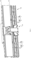
- Fig. 9 is a partial sectional view of an embodiment of a rotary gripper 500 that is driven by power provided to the moving element as noted above.
- the rotary gripper 500 includes a body 505 and a rotary head 510, with the rotary head and body having a hollow shaft 515 formed therein.
- the body also includes a spindle motor 520 and a gripper motor 525.
- the rotary head 510 is provided with one or more gripper fingers 530.
- the gripper motor 525 is operated to adjust the gripper fingers 530, for example through a mechanical linkage or the like, to grip a part/product inserted into the hollow shaft and the spindle motor is operated to rotate the rotary head, and thus rotate the part/product held by the gripper fingers.
- the rotary gripper can further include a cam plate 535, a plurality of cam followers 540, and a plurality of torsion springs 545 as explained below.
- these elements do not need to be present in all embodiments.
- the spindle motor rotates the rotary head (and thus the gripper fingers) about an axis of rotation (which is, for example, a center of the hollow shaft) and establishes the overall rotational speed, acceleration and deceleration of the part being held.
- the rotary gripper may include a spindle encoder for the spindle motor, such that the spindle motor may follow a prescribed motion profile based on the spindle encoder feedback.
- the gripper fingers are generally at fixed angles relative to the spindle motor.
- a gripper encoder may also be provided for the gripper motor, if required based on the type of motor used.
- the rotary gripper 500 includes the cam plate 535 and the plurality of cam followers 540, which are configured such that the cam followers can engage with or be in mechanical communication with an associated gripper finger while also in contact with the cam plate.
- Each cam follower is configured to move the gripper finger radially based on movement of the cam plate.
- the cam plate can be formed with a groove for each gripper finger and its associated cam follower. The grooves in the cam plate can be of a fixed width to match the diameter of the cam follower and have a radial distance from the centreline of the axis of rotation that varies at each angular position around the cam plate.
- the gripper motor is responsible for positioning the cam plate relative to the spindle motor and in turn, positioning the associated cam followers with their associated gripper fingers.
- the gripper fingers can be used to grip parts/components with force or to locate parts/components by positioning fingers close to the parts/components without force.
- the gripper motor rotates the cam plate to a position/angle that moves the cam followers and places each gripper finger in an appropriate position for the required task.
- the gripper motor When locating, the gripper motor can maintain a relative angular position of the cam plate to the spindle motor.
- the closing torque of the gripper motor can be controlled to a predetermined value (potentially plus/minus a predetermined error limit). This limit on the gripper motor torque can be configured such that the gripping force is maintained between a minimum and maximum force. Further, the torque, and thus the gripping force, can be fully programmable.
- the plurality of torsion springs 545 can be mounted coaxially with the axis of rotation and may be used to provide a complimentary torque to assist in closing or opening the gripper fingers as required.
- the rotary gripper and cam plate can be configured such that, during angular acceleration, both motors are rotating in a common direction and providing complimentary torques for acceleration. With this configuration, the motor torques will counteract each other during deceleration.
- the cam profile configuration can be reversed, which will reverse the complimentary or counteracting torques during acceleration or deceleration. The configuration can be determined as desired according to the motion profile requirements or other process requirements.
- the gripping motor torque can be configured to provide either a varying gripping force at varying diameters or an identical gripping force at all diameters of parts/components.
- the gripping forces are adjustable/configurable/programmable.
- a benefit of this configuration of the rotary gripper is that each motor can be directly coupled to its associated rotating elements resulting in a stiff system which can respond quickly to errors associated with position or torque.
- This configuration can also provide reduced weight and reduce/eliminate any need for transmission elements, which may wear and/or require maintenance.
- the provision of the torsion spring can allow parts to be held by the gripper even when power to the motors is off. Further, the ability to adjust the gripper fingers variably allows the rotary gripper to grip a range of part diameter sizes without changing out the gripper fingers. The range is determined by the dimensions of, for example, grooves on the cam plate.
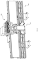
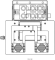
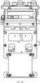
- FIGS. 10 and 11 illustrate other embodiments of a moving element and related accessory 1000, 1100.
- the accessory 1000, 1100 is a plurality of rotary grippers similar to the rotary gripper 500 which are mounted such that they are facing upward or downward to illustrate that various positions may be possible.
- the accessory 1000, 1100 may be mounted to an adjustable mount such that the position can be changed when stopped or a further motor can be added to the moving element to allow adjustment of the accessory 1000, 1100 during movement, using, for example, power supplied to the moving element.
- the ability to adjust the position/orientation of the accessory is facilitated when there is no need for an external power source. Further, the weight of items on the moving element can be reduced when there is no need for battery storage such as a battery or the like.
- the accessory can include a plurality of items such as the rotary grippers discussed herein.
- the accessory may be one rotary gripper or more up to the number that can be accommodated on the moving element.
- the accessory can be any of various types including grippers, part/component adjustment mechanisms, motors or various kinds, robots, or the like.
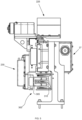
- the vacuum pump 1205 can be controlled by an accessory controller in, for example, an enclosure 1235 on the moving element. Having a vacuum source available at the moving element can allow for easier handling of delicate/fragile parts such as glass, solar panels or the like that might be harmed by more direct contact. Vacuum can also be useful in handling parts that may lack available or useful mechanical gripping surfaces, have unusual shapes or the like. For example, parts that have an irregular shape or where there are parts with different sizes/formats that need to be gripped on the same moving element.
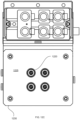
- Figures 13A , 13B , 13C illustrate another accessory 1300 that can be provided on a moving element and powered by inductive power provided to the moving element.
- Fig. 13A is a perspective view of a gripper system 1300 provided to a moving element.
- Fig. 13B is a front view and
- Fig. 13C is a top view of the gripper system 1300.
- the gripper system 1300 includes a drive mechanism and gripper arms that can be moved by the drive mechanism to allow for gripping items on a surface of a pallet carried by the moving element.
- the gripper system may also include a feedback mechanism.
- the gripper system 1300 can be controlled by an accessory controller in, for example, the enclosure on the moving element.
- the gripper system can be used for applications that require some form of adjustable containment (perhaps with a clearance) for a range of part sizes or the like.
- the gripper system can be used to check part weight without having to transfer the part to a separate weigh station.
- some gripper arms may have force control to allow for gripping delicate parts at a controlled force.
- the use of a gripper system on the moving element may allow for easier handling of rejected parts or the like.
- the various controllers may be connected via, for example, input/output (I/O) or network modules or the like.
- the controllers may provide instructions to both the accessories and the track section 25/moving element 35, such as directing the next destination for a moving element 35 along the track, providing instructions to operate in a specific way depending on the location of the moving element on the track section, or the like.
- the rotary gripper may be controlled to rotate a part/component as the moving element moves past a flame station adjacent to the track section such that the part/component is uniformly heated around a circumference or the like.
- inductive power When inductive power is available on the moving element/pallet, it is useful to also be able to communicate with the accessory provided on the moving element in a wireless manner. In some cases, it may also be useful to communicate with or among track section controllers in a wireless manner.
- the provision of wireless instructions to accessories in a manufacturing environment can be difficult due to the need for high levels of reliability and the fast communications that are needed due to the fast speeds and accelerations of the conveyor and automation stations.
- the fast communications typically require smaller/faster communications, but reliability typically requires more data.
- the difficulty of communications can be increased when the accessory is more complex and may have more commands that can be performed, such as where servo motors and sensors are used.
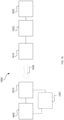
- FIG 16 is a block diagram of an embodiment of a wireless communication system 1600 that can be used with embodiments of the conveyor system herein.
- the illustrated wireless communication system 1600 is directed at communication to an accessory (from either a central controller or a track section controller), a similar approach may be available for communications from a central controller to a track section controller or the like.
- the wireless communication system 1600 is configured to allow communication between a conveyor or track controller and an accessory controller.
- the wireless communication system 1600 can operate between a master controller 1605 (for example, a programmable logic controller (PLC) or the like) and an accessory 1625.
- the system 1600 includes a downlink converter/transmitter 1610, an accessory receiver/transmitter 1615, and an accessory interface 1620.
- the master controller 1605 may be the central controller for the conveyor system and communicate with the downlink converter/transmitter directly or, in some cases, the communication may be from a master controller via a track section controller 1607 or from a track section controller 1607 directly, depending on the overall communications approach determined in relation to Fig. 15 .
- the master controller 1605 can issue instructions to the accessory and the instructions will be converted/translated by the downlink converter 1610 to a more concise communication format/protocol for transmission over the wireless link (illustrated by arrow 1630).
- the concise format instructions are received by the accessory receiver/transmitter 1615 and passed to the accessory interface 1620, which provides instructions to the accessory 1625.
- the accessory interface 1620 may convert the instructions for the accessory 1625, if needed.
- the concise communication format/protocol can use multiple repeat messages with error checking and can generally limit each message to as small a size as possible by using, for example, default states, default conditions, and the like.
Landscapes
- Engineering & Computer Science (AREA)
- Computer Networks & Wireless Communication (AREA)
- Signal Processing (AREA)
- Power Engineering (AREA)
- Mechanical Engineering (AREA)
- Health & Medical Sciences (AREA)
- Computing Systems (AREA)
- General Health & Medical Sciences (AREA)
- Medical Informatics (AREA)
- Non-Mechanical Conveyors (AREA)
Claims (7)
- System (300) zur Versorgung einer Zusatzvorrichtung auf einem beweglichen Element (35) auf einem Förderband (20) mit Energie, während sich das bewegliche Element bewegt, wobei das System Folgendes umfasst:eine Vielzahl von beweglichen Elementen, wobei jedes bewegliche Element eine Energieübertragungseinheit (305) des beweglichen Elements umfasst, die eine oder mehrere Energieaufnahmeplatten (315) umfasst; undmindestens einen Bahnabschnitt (25), dem die Vielzahl von beweglichen Elementen zugeordnet ist, wobei der Bahnabschnitt Folgendes umfasst:ein Steuersystem (40);eine Bahn, auf der sich die Vielzahl von beweglichen Elementen bewegt; undeine Energieübertragungseinheit (310), die eine Vielzahl von induktiven Platten (320) umfasst,dadurch gekennzeichnet, dasssich die eine oder die mehreren Energieaufnahmeplatten zu dem Bahnabschnitt und in Lücken zwischen der Vielzahl von induktiven Platten erstrecken, die sich jeweils derart zu dem beweglichen Element erstrecken, dass die eine oder die mehreren Energieaufnahmeplatten und die Vielzahl von induktiven Platten auf verschränkte Art und Weise überlappen.
- System nach Anspruch 1, wobei die Zusatzvorrichtung (100, 1000, 1100) mindestens einen Drehgreifer (500) umfasst, wobei der Drehgreifer Folgendes umfasst:einen Körper (505);einen Greifermotor (525);einen Rotationsmotor (520); undeine Vielzahl von Greifern (530),wobei der Greifermotor mechanisch mit der Vielzahl von Greifern verbunden ist und dazu konfiguriert ist, diese zu öffnen und zu schließen, und der Rotationsmotor mechanisch mit der Vielzahl von Greifern verbunden ist und dazu konfiguriert ist, diese zu drehen.
- System nach Anspruch 2, wobei die Zusatzvorrichtung ferner Folgendes umfasst:eine Nockenscheibe (535), die mechanisch mit dem Greifermotor verbunden ist; undNockenstößel (540) in Kontakt mit der Nockenscheibe und jedem der Vielzahl von Greifern, wobei eine Bewegung der Nockenscheibe durch den Greifermotor das Öffnen und Schließen der Vielzahl von Greifern über die Nockenstößel steuert.
- System nach Anspruch 3, wobei die Zusatzvorrichtung ferner eine den Nockenstößeln bereitgestellte Vielzahl von Torsionsfedern (545) umfasst, die dazu konfiguriert ist, die Vielzahl von Greifern in eine geschlossene Position vorzuspannen.
- System nach einem der Ansprüche 2 bis 4, wobei die Zusatzvorrichtung ferner Folgendes umfasst:eine dem beweglichen Element bereitgestellte Zusatzvorrichtungssteuerung (1515),wobei die Zusatzvorrichtungssteuerung dazu konfiguriert ist, den Greifermotor und den Rotationsmotor auf Grundlage von drahtloser Kommunikation von einer Master-Steuerung (1505, 1605) zu betreiben.
- System nach einem der Ansprüche 2 bis 5, wobei die Zusatzvorrichtung ferner einen Sensor umfasst, um die Kraft der Vielzahl von Greifern an einem Teil zu erfassen.
- System nach einem der Ansprüche 1 bis 6, ferner umfassend:
ein System zur drahtlosen Kommunikation (1600) zur Kommunikation zwischen dem Steuersystem und der Zusatzvorrichtung,
wobei das System zur drahtlosen Kommunikation Befehls-ID-Codes und ein Toggling Bit verwendet, das eine aktive Zusatzvorrichtung angibt, damit Nachrichten kleiner als 2 Bytes bleiben.
Applications Claiming Priority (1)
| Application Number | Priority Date | Filing Date | Title |
|---|---|---|---|
| US202163168729P | 2021-03-31 | 2021-03-31 |
Publications (3)
| Publication Number | Publication Date |
|---|---|
| EP4068568A1 EP4068568A1 (de) | 2022-10-05 |
| EP4068568C0 EP4068568C0 (de) | 2025-07-02 |
| EP4068568B1 true EP4068568B1 (de) | 2025-07-02 |
Family
ID=81074209
Family Applications (2)
| Application Number | Title | Priority Date | Filing Date |
|---|---|---|---|
| EP22165810.7A Active EP4068568B1 (de) | 2021-03-31 | 2022-03-31 | System und verfahren zur versorgung eines beweglichen elements auf einem förderband mit energie und durch die versorgung eines beweglichen elements mit energie angetriebenes zubehör |
| EP22165826.3A Pending EP4071970A1 (de) | 2021-03-31 | 2022-03-31 | Verfahren und system zur drahtlosen kommunikation in einem fördersystem |
Family Applications After (1)
| Application Number | Title | Priority Date | Filing Date |
|---|---|---|---|
| EP22165826.3A Pending EP4071970A1 (de) | 2021-03-31 | 2022-03-31 | Verfahren und system zur drahtlosen kommunikation in einem fördersystem |
Country Status (2)
| Country | Link |
|---|---|
| US (2) | US12397999B2 (de) |
| EP (2) | EP4068568B1 (de) |
Families Citing this family (2)
| Publication number | Priority date | Publication date | Assignee | Title |
|---|---|---|---|---|
| EP4572345A3 (de) * | 2023-11-22 | 2025-09-03 | ATS Corporation | Verfahren und system zur drahtlosen kommunikation in einem fördersystem |
| US20250340385A1 (en) | 2024-05-06 | 2025-11-06 | Ats Corporation | Shuttle diverter for a linear motor conveyor system |
Citations (2)
| Publication number | Priority date | Publication date | Assignee | Title |
|---|---|---|---|---|
| US6089512A (en) * | 1995-04-03 | 2000-07-18 | Daimler-Benz Aktiengesellschaft | Track-guided transport system with power and data transmission |
| US6499701B1 (en) * | 1999-07-02 | 2002-12-31 | Magnemotion, Inc. | System for inductive transfer of power, communication and position sensing to a guideway-operated vehicle |
Family Cites Families (15)
| Publication number | Priority date | Publication date | Assignee | Title |
|---|---|---|---|---|
| US6708385B1 (en) * | 1954-07-28 | 2004-03-23 | Lemelson Medical, Education And Research Foundation, Lp | Flexible manufacturing systems and methods |
| US5709291A (en) * | 1992-05-22 | 1998-01-20 | Daifuku Co., Ltd. | Device for contactless power supply to moving body |
| DE19845527A1 (de) * | 1998-10-02 | 2000-04-06 | Beumer Maschf Bernhard | Gliederförderer (Sorter) zum Sortieren von Stückgutteilen |
| US6374748B1 (en) * | 1999-10-28 | 2002-04-23 | Murata Kikai Kabushiki Kaisha | Tracking cart system |
| US7280889B2 (en) * | 2002-03-08 | 2007-10-09 | Humphrey Products Company | Networkable zone control modules and method and coveyor system incorporating the same |
| US8800745B2 (en) * | 2008-05-09 | 2014-08-12 | Caterpillar Inc. | Modular manufacturing line including work tool having work tool spray nozzle and method of operation therefor |
| EP2403785B1 (de) * | 2009-03-03 | 2013-05-01 | ATS Automation Tooling Systems Inc. | Multimodales multi-steigungs-fördersystem |
| US9333875B2 (en) | 2010-07-29 | 2016-05-10 | Ats Automation Tooling Systems Inc. | System and method for providing power to a moving element |
| US9422121B2 (en) * | 2011-09-30 | 2016-08-23 | Ats Automation Tooling Systems Inc. | System for providing vacuum to a moving element |
| JP6698399B2 (ja) * | 2016-03-29 | 2020-05-27 | 北陽電機株式会社 | 搬送制御装置及び搬送台車の合流点通過方法 |
| PL3452391T3 (pl) * | 2016-05-06 | 2024-07-01 | Comau Llc | System odwróconej windy transportowej |
| AU2018328746A1 (en) * | 2017-09-05 | 2020-03-26 | Innovate Holdings Pty Ltd | Conveyor module assembly, system and control |
| DE102018111715A1 (de) * | 2018-05-16 | 2019-11-21 | Beckhoff Automation Gmbh | Lineares transportsystem und system zur kontaktlosen energie- und datenübertragung |
| WO2020105192A1 (ja) * | 2018-11-22 | 2020-05-28 | 株式会社Fuji | 走行装置 |
| DE102020110795A1 (de) * | 2020-04-21 | 2021-10-21 | Beckhoff Automation Gmbh | Anschalteinheit in einem linearen Transportsystem |
-
2022
- 2022-03-31 EP EP22165810.7A patent/EP4068568B1/de active Active
- 2022-03-31 US US17/710,167 patent/US12397999B2/en active Active
- 2022-03-31 US US17/710,129 patent/US20220315357A1/en active Pending
- 2022-03-31 EP EP22165826.3A patent/EP4071970A1/de active Pending
Patent Citations (2)
| Publication number | Priority date | Publication date | Assignee | Title |
|---|---|---|---|---|
| US6089512A (en) * | 1995-04-03 | 2000-07-18 | Daimler-Benz Aktiengesellschaft | Track-guided transport system with power and data transmission |
| US6499701B1 (en) * | 1999-07-02 | 2002-12-31 | Magnemotion, Inc. | System for inductive transfer of power, communication and position sensing to a guideway-operated vehicle |
Also Published As
| Publication number | Publication date |
|---|---|
| EP4071970A1 (de) | 2022-10-12 |
| EP4068568C0 (de) | 2025-07-02 |
| US20220315348A1 (en) | 2022-10-06 |
| US20220315357A1 (en) | 2022-10-06 |
| US12397999B2 (en) | 2025-08-26 |
| EP4068568A1 (de) | 2022-10-05 |
Similar Documents
| Publication | Publication Date | Title |
|---|---|---|
| EP4068568B1 (de) | System und verfahren zur versorgung eines beweglichen elements auf einem förderband mit energie und durch die versorgung eines beweglichen elements mit energie angetriebenes zubehör | |
| US9096386B2 (en) | Multi-mode scroll cam conveyor system | |
| EP0722811B1 (de) | Roboter ohne kabelverbindung | |
| US11929655B2 (en) | Transport system and processing system | |
| EP2691319B1 (de) | Positionseinstellsystem für paletten | |
| CN106170382B (zh) | 用于运输和搬运容器的装置和方法以及吹塑成型机 | |
| CN112589783A (zh) | 用于夹持和/或保持物体的机器人 | |
| JPH0897597A (ja) | 電子部品装着装置 | |
| EP3941861B1 (de) | Fördervorrichtung | |
| US12338083B2 (en) | System for handling individual primary packaging containers | |
| KR20230149805A (ko) | 제품 취급 장치, 시스템, 및 관련 방법 | |
| EP4572345A2 (de) | Verfahren und system zur drahtlosen kommunikation in einem fördersystem | |
| CN218200610U (zh) | 用于输送物体的装置和用于处理容器的装置 | |
| EP4237235A1 (de) | System und verfahren zum zusammenbau einer verpackung | |
| EP3578335A1 (de) | Gerät zum greifen und bewegen von vorformlingen/flaschen auf einer bahn in einer vorformlingbehandlungsanlage für die herstellung von flaschen | |
| CN119796953A (zh) | 运输加工系统 | |
| JP6434710B2 (ja) | 搬送システム及び加工システム |
Legal Events
| Date | Code | Title | Description |
|---|---|---|---|
| PUAI | Public reference made under article 153(3) epc to a published international application that has entered the european phase |
Free format text: ORIGINAL CODE: 0009012 |
|
| STAA | Information on the status of an ep patent application or granted ep patent |
Free format text: STATUS: THE APPLICATION HAS BEEN PUBLISHED |
|
| AK | Designated contracting states |
Kind code of ref document: A1 Designated state(s): AL AT BE BG CH CY CZ DE DK EE ES FI FR GB GR HR HU IE IS IT LI LT LU LV MC MK MT NL NO PL PT RO RS SE SI SK SM TR |
|
| STAA | Information on the status of an ep patent application or granted ep patent |
Free format text: STATUS: REQUEST FOR EXAMINATION WAS MADE |
|
| 17P | Request for examination filed |
Effective date: 20230329 |
|
| RBV | Designated contracting states (corrected) |
Designated state(s): AL AT BE BG CH CY CZ DE DK EE ES FI FR GB GR HR HU IE IS IT LI LT LU LV MC MK MT NL NO PL PT RO RS SE SI SK SM TR |
|
| GRAP | Despatch of communication of intention to grant a patent |
Free format text: ORIGINAL CODE: EPIDOSNIGR1 |
|
| STAA | Information on the status of an ep patent application or granted ep patent |
Free format text: STATUS: GRANT OF PATENT IS INTENDED |
|
| RIC1 | Information provided on ipc code assigned before grant |
Ipc: B65G 54/02 20060101ALI20250122BHEP Ipc: H02J 50/00 20160101AFI20250122BHEP |
|
| INTG | Intention to grant announced |
Effective date: 20250206 |
|
| RAP3 | Party data changed (applicant data changed or rights of an application transferred) |
Owner name: ATS CORPORATION |
|
| GRAS | Grant fee paid |
Free format text: ORIGINAL CODE: EPIDOSNIGR3 |
|
| GRAA | (expected) grant |
Free format text: ORIGINAL CODE: 0009210 |
|
| STAA | Information on the status of an ep patent application or granted ep patent |
Free format text: STATUS: THE PATENT HAS BEEN GRANTED |
|
| AK | Designated contracting states |
Kind code of ref document: B1 Designated state(s): AL AT BE BG CH CY CZ DE DK EE ES FI FR GB GR HR HU IE IS IT LI LT LU LV MC MK MT NL NO PL PT RO RS SE SI SK SM TR |
|
| REG | Reference to a national code |
Ref country code: GB Ref legal event code: FG4D |
|
| REG | Reference to a national code |
Ref country code: CH Ref legal event code: EP |
|
| REG | Reference to a national code |
Ref country code: DE Ref legal event code: R096 Ref document number: 602022016681 Country of ref document: DE |
|
| REG | Reference to a national code |
Ref country code: IE Ref legal event code: FG4D |
|
| U01 | Request for unitary effect filed |
Effective date: 20250721 |
|
| U07 | Unitary effect registered |
Designated state(s): AT BE BG DE DK EE FI FR IT LT LU LV MT NL PT RO SE SI Effective date: 20250728 |
|
| U1N | Appointed representative for the unitary patent procedure changed after the registration of the unitary effect |
Representative=s name: MURGITROYD & COMPANY; GB |
|
| PG25 | Lapsed in a contracting state [announced via postgrant information from national office to epo] |
Ref country code: IS Free format text: LAPSE BECAUSE OF FAILURE TO SUBMIT A TRANSLATION OF THE DESCRIPTION OR TO PAY THE FEE WITHIN THE PRESCRIBED TIME-LIMIT Effective date: 20251102 |
|
| PG25 | Lapsed in a contracting state [announced via postgrant information from national office to epo] |
Ref country code: NO Free format text: LAPSE BECAUSE OF FAILURE TO SUBMIT A TRANSLATION OF THE DESCRIPTION OR TO PAY THE FEE WITHIN THE PRESCRIBED TIME-LIMIT Effective date: 20251002 |
|
| PG25 | Lapsed in a contracting state [announced via postgrant information from national office to epo] |
Ref country code: HR Free format text: LAPSE BECAUSE OF FAILURE TO SUBMIT A TRANSLATION OF THE DESCRIPTION OR TO PAY THE FEE WITHIN THE PRESCRIBED TIME-LIMIT Effective date: 20250702 |
|
| PG25 | Lapsed in a contracting state [announced via postgrant information from national office to epo] |
Ref country code: GR Free format text: LAPSE BECAUSE OF FAILURE TO SUBMIT A TRANSLATION OF THE DESCRIPTION OR TO PAY THE FEE WITHIN THE PRESCRIBED TIME-LIMIT Effective date: 20251003 |
|
| PG25 | Lapsed in a contracting state [announced via postgrant information from national office to epo] |
Ref country code: CZ Free format text: LAPSE BECAUSE OF FAILURE TO SUBMIT A TRANSLATION OF THE DESCRIPTION OR TO PAY THE FEE WITHIN THE PRESCRIBED TIME-LIMIT Effective date: 20250702 |
|
| PG25 | Lapsed in a contracting state [announced via postgrant information from national office to epo] |
Ref country code: PL Free format text: LAPSE BECAUSE OF FAILURE TO SUBMIT A TRANSLATION OF THE DESCRIPTION OR TO PAY THE FEE WITHIN THE PRESCRIBED TIME-LIMIT Effective date: 20250702 |
|
| PG25 | Lapsed in a contracting state [announced via postgrant information from national office to epo] |
Ref country code: RS Free format text: LAPSE BECAUSE OF FAILURE TO SUBMIT A TRANSLATION OF THE DESCRIPTION OR TO PAY THE FEE WITHIN THE PRESCRIBED TIME-LIMIT Effective date: 20251002 |
|
| PG25 | Lapsed in a contracting state [announced via postgrant information from national office to epo] |
Ref country code: ES Free format text: LAPSE BECAUSE OF FAILURE TO SUBMIT A TRANSLATION OF THE DESCRIPTION OR TO PAY THE FEE WITHIN THE PRESCRIBED TIME-LIMIT Effective date: 20250702 |