EP4067764B1 - Kombiniertes kühlsystem und freies kühlsystem für den betrieb bei hoher umgebungstemperatur - Google Patents
Kombiniertes kühlsystem und freies kühlsystem für den betrieb bei hoher umgebungstemperatur Download PDFInfo
- Publication number
- EP4067764B1 EP4067764B1 EP22156605.2A EP22156605A EP4067764B1 EP 4067764 B1 EP4067764 B1 EP 4067764B1 EP 22156605 A EP22156605 A EP 22156605A EP 4067764 B1 EP4067764 B1 EP 4067764B1
- Authority
- EP
- European Patent Office
- Prior art keywords
- coolant
- valve
- temperature
- line
- coolant line
- Prior art date
- Legal status (The legal status is an assumption and is not a legal conclusion. Google has not performed a legal analysis and makes no representation as to the accuracy of the status listed.)
- Active
Links
Images




Classifications
-
- F—MECHANICAL ENGINEERING; LIGHTING; HEATING; WEAPONS; BLASTING
- F25—REFRIGERATION OR COOLING; COMBINED HEATING AND REFRIGERATION SYSTEMS; HEAT PUMP SYSTEMS; MANUFACTURE OR STORAGE OF ICE; LIQUEFACTION SOLIDIFICATION OF GASES
- F25B—REFRIGERATION MACHINES, PLANTS OR SYSTEMS; COMBINED HEATING AND REFRIGERATION SYSTEMS; HEAT PUMP SYSTEMS
- F25B49/00—Arrangement or mounting of control or safety devices
- F25B49/02—Arrangement or mounting of control or safety devices for compression type machines, plants or systems
-
- F—MECHANICAL ENGINEERING; LIGHTING; HEATING; WEAPONS; BLASTING
- F24—HEATING; RANGES; VENTILATING
- F24F—AIR-CONDITIONING; AIR-HUMIDIFICATION; VENTILATION; USE OF AIR CURRENTS FOR SCREENING
- F24F11/00—Control or safety arrangements
- F24F11/30—Control or safety arrangements for purposes related to the operation of the system, e.g. for safety or monitoring
-
- F—MECHANICAL ENGINEERING; LIGHTING; HEATING; WEAPONS; BLASTING
- F24—HEATING; RANGES; VENTILATING
- F24F—AIR-CONDITIONING; AIR-HUMIDIFICATION; VENTILATION; USE OF AIR CURRENTS FOR SCREENING
- F24F11/00—Control or safety arrangements
- F24F11/70—Control systems characterised by their outputs; Constructional details thereof
- F24F11/80—Control systems characterised by their outputs; Constructional details thereof for controlling the temperature of the supplied air
- F24F11/83—Control systems characterised by their outputs; Constructional details thereof for controlling the temperature of the supplied air by controlling the supply of heat-exchange fluids to heat-exchangers
- F24F11/84—Control systems characterised by their outputs; Constructional details thereof for controlling the temperature of the supplied air by controlling the supply of heat-exchange fluids to heat-exchangers using valves
-
- F—MECHANICAL ENGINEERING; LIGHTING; HEATING; WEAPONS; BLASTING
- F24—HEATING; RANGES; VENTILATING
- F24F—AIR-CONDITIONING; AIR-HUMIDIFICATION; VENTILATION; USE OF AIR CURRENTS FOR SCREENING
- F24F11/00—Control or safety arrangements
- F24F11/70—Control systems characterised by their outputs; Constructional details thereof
- F24F11/80—Control systems characterised by their outputs; Constructional details thereof for controlling the temperature of the supplied air
- F24F11/87—Control systems characterised by their outputs; Constructional details thereof for controlling the temperature of the supplied air by controlling absorption or discharge of heat in outdoor units
-
- F—MECHANICAL ENGINEERING; LIGHTING; HEATING; WEAPONS; BLASTING
- F25—REFRIGERATION OR COOLING; COMBINED HEATING AND REFRIGERATION SYSTEMS; HEAT PUMP SYSTEMS; MANUFACTURE OR STORAGE OF ICE; LIQUEFACTION SOLIDIFICATION OF GASES
- F25B—REFRIGERATION MACHINES, PLANTS OR SYSTEMS; COMBINED HEATING AND REFRIGERATION SYSTEMS; HEAT PUMP SYSTEMS
- F25B13/00—Compression machines, plants or systems, with reversible cycle
-
- F—MECHANICAL ENGINEERING; LIGHTING; HEATING; WEAPONS; BLASTING
- F25—REFRIGERATION OR COOLING; COMBINED HEATING AND REFRIGERATION SYSTEMS; HEAT PUMP SYSTEMS; MANUFACTURE OR STORAGE OF ICE; LIQUEFACTION SOLIDIFICATION OF GASES
- F25B—REFRIGERATION MACHINES, PLANTS OR SYSTEMS; COMBINED HEATING AND REFRIGERATION SYSTEMS; HEAT PUMP SYSTEMS
- F25B25/00—Machines, plants or systems, using a combination of modes of operation covered by two or more of the groups F25B1/00 - F25B23/00
- F25B25/005—Machines, plants or systems, using a combination of modes of operation covered by two or more of the groups F25B1/00 - F25B23/00 using primary and secondary systems
-
- F—MECHANICAL ENGINEERING; LIGHTING; HEATING; WEAPONS; BLASTING
- F25—REFRIGERATION OR COOLING; COMBINED HEATING AND REFRIGERATION SYSTEMS; HEAT PUMP SYSTEMS; MANUFACTURE OR STORAGE OF ICE; LIQUEFACTION SOLIDIFICATION OF GASES
- F25B—REFRIGERATION MACHINES, PLANTS OR SYSTEMS; COMBINED HEATING AND REFRIGERATION SYSTEMS; HEAT PUMP SYSTEMS
- F25B41/00—Fluid-circulation arrangements
- F25B41/20—Disposition of valves, e.g. of on-off valves or flow control valves
-
- F—MECHANICAL ENGINEERING; LIGHTING; HEATING; WEAPONS; BLASTING
- F25—REFRIGERATION OR COOLING; COMBINED HEATING AND REFRIGERATION SYSTEMS; HEAT PUMP SYSTEMS; MANUFACTURE OR STORAGE OF ICE; LIQUEFACTION SOLIDIFICATION OF GASES
- F25B—REFRIGERATION MACHINES, PLANTS OR SYSTEMS; COMBINED HEATING AND REFRIGERATION SYSTEMS; HEAT PUMP SYSTEMS
- F25B2339/00—Details of evaporators; Details of condensers
- F25B2339/04—Details of condensers
- F25B2339/047—Water-cooled condensers
Definitions
- HVAC heating, ventilation, and air conditioning
- Chiller systems may be used in cooling air for relatively large spaces, such as commercial buildings, industries, schools, data centers, and the like.
- a chiller system may cool a refrigerant by transferring heat to outdoor air. The cooled refrigerant is then used to cool a flow of coolant, which is delivered to an indoor system in order to cool air that is provided to the space.
- Patent literature EP 3 351 862 A discloses a HVAC system for a building comprising a chiller configured to provide mechanical cooling for a cooling load in the building when the HVAC system operates in a mechanical cooling state, and a heat exchanger - separate from the chiller - configured to provide free cooling for the cooling load in the building when the HVAC system operates in a free cooling state; depending on an outside air temperature predicted by a controller, the mechanical cooling or free cooling operation will be determined.
- a chiller system cools a flow of refrigerant, through a refrigeration cycle involving heat transfer with outdoor air and uses this cooled refrigerant to cool a flow of coolant.
- the coolant is then delivered to an indoor unit to cool air that is provided to an enclosed, or indoor, space.
- the outdoor ambient temperature is sufficiently low for the coolant to be directly cooled by the air without requiring the refrigeration cycle of a typical chiller.
- Such direct cooling at relatively low ambient temperatures may be referred to as "free cooling.” Free cooling may be available in spaces that still have a cooling demand even when the outdoor temperature is relatively low, such as offices with high internal loads like computer rooms, data centers, and the like. For example, free cooling may particularly be available in locations where outdoor air temperatures are below 5 °C for a significant portion of each year.
- a free cooling unit in order to implement free cooling in previous systems, a free cooling unit must be added to a chiller unit (e.g., via retrofitting of an existing chiller unit). This can result in various disadvantages and inefficiencies.
- the use of a separate chiller unit and free cooling unit results in the inefficient use of heat transfer area because condensers of one unit will always be inactive. For example, when the outdoor ambient temperature is relatively high, the chiller unit may be operated, while the heat transfer resources (e.g., the heat transfer coils) of the free cooling unit are unused. Similarly, during low outdoor temperature conditions, the free cooler unit may be operated, while the condensers of the chiller are idle or not used.
- the system in certain embodiments, includes a combined chiller/free cooling unit.
- the system according to the invention is defined in claim 1.
- This unit includes outdoor coils arranged in parallel, such that a first-side inlet of each coil is in fluid communication with a first-side coolant line and a second-side outlet of each coil is in fluid communication with the same second-side coolant line.
- a first valve is located in the first-side coolant line and a second valve is located in the second-side coolant line to separate the coils into a first set of coils on one side of the first and second valves and a second set of coils on the other side of the first and second valves.
- a third valve is positioned to regulate the flow of coolant from the second-side coolant line on the side of the second set of coils toward a water evaporator.
- a fourth valve is positioned to regulate a flow of coolant from the second-side coolant line (on the side of the first set of coils) to a water condenser.
- valves are controlled by a controller, which is defined in claim 14 and configured to operate the unit in an appropriate mode based, for instance, on environmental and/or setpoint conditions.
- a controller which is defined in claim 14 and configured to operate the unit in an appropriate mode based, for instance, on environmental and/or setpoint conditions.
- the first, second, and fourth valves may be adjusted to an open position, while the third valve is adjusted to a closed position.
- This valve configuration corresponds to both the first and second sets of coils acting as chillers (e.g., where cooling is facilitated via contact with a refrigerant undergoing a vapor compression refrigeration cycle).
- the first, second, and third valves are adjusted to open positions, while the fourth valve is adjusted to a closed position.
- This valve configuration corresponds to both the first and second sets of coils acting as a free cooling unit (e.g., where cooling is facilitated through heat transfer with cool outdoor air).
- the third and fourth valves are adjusted to open positions, while the first and second valves are adjusted to a closed position.
- This valve configuration corresponds to the first set of coils acting as chillers (e.g., where cooling is facilitated via contact with a refrigerant undergoing a vapor compression refrigeration cycle) and the second sets of coils acting as a free cooling unit (e.g., where cooling is facilitated through heat transfer with cool outdoor air).
- the combined chiller/free cooling unit described in this disclosure allows the full (i.e., entire) heat transfer area of the unit to be used under all operating conditions, such that cooling resources are not wasted, left unused, or otherwise left idle during portions of the year.
- the combined chiller/free cooling unit improves the efficiency of providing cooling to a space by ensuring that an efficient combination of refrigerant-based cooling (i.e., cooling involving a refrigeration cycle) and/or free cooling (i.e., cooling provided directly from a cool ambient environment) are selected.
- a controller of the combined chiller/free cooling unit may operate in one of several modes for improving cooling efficiency.
- valves may be adjusted to operate the combined chiller/free cooling unit in a high temperature mode where both the first and second sets of coils are configured for refrigerant-based cooling (se FIG. 2 ).
- the controller may adjust valves of the combined chiller/free cooling unit such both first and second sets of coils are configured for free cooling (see FIG. 3 ).
- the controller operates the unit in a mode in which cooling is provided by both refrigerant-based cooling and the free cooling (see FIG. 4 ).
- a plurality of valves are positioned and configured such that heat transfer resources (e.g., the various coils) can be redistributed amongst the refrigerant-based cooling portion and the free cooling portion, further increasing the overall efficiency of cooling operations (see FIG. 5 ).
- the combined chiller/free cooling unit of this disclosure may allow free cooling to be used at higher ambient temperatures than was possible using previous technology by supplementing free cooling with refrigerant-based cooling.
- a system in an embodiment, includes a first set of coils configured to receive coolant from a first coolant line, transfer heat from the coolant to outdoor air, and provide the coolant to a second coolant line.
- a second set of coils is configured to receive coolant from a third coolant line, transfer heat from the coolant to outdoor air, and provide the coolant to a fourth coolant line.
- a first valve is positioned and configured to regulate flow of the coolant between the first coolant line and the third coolant line.
- a second valve is positioned and configured to regulate flow of the coolant between the second coolant line and the fourth coolant line.
- a third valve is positioned and configured to regulate flow of coolant between the fourth coolant line and a fifth coolant line.
- the fifth coolant line is coupled to a water evaporator and a three-way valve.
- the three-way valve is configured to regulate flow of the coolant between the fifth coolant line, the third coolant line, and a coolant input line.
- a fourth valve is positioned and configured to regulate flow of the coolant between the first coolant line and a water condenser.
- a compressor is configured to compress a refrigerant provided to the water condenser.
- a controller receives an outdoor temperature and an indoor setpoint temperature.
- the controller determines, based on a comparison of the outdoor temperature to the indoor setpoint temperature, that the system should operate in a high-temperature operating mode.
- the first valve is caused to be in an open position such that flow of the coolant is allowed between the first coolant line and the third coolant line.
- the second valve is caused to be in the open position such that flow of the coolant is allowed between the second coolant line and the fourth coolant line.
- the third valve is caused to be in a closed position such that flow of the coolant is prevented between the fourth coolant line and the fifth coolant line.
- the fourth valve is caused to be in the open position such that flow of the coolant is allowed between the second coolant line and the water condenser.
- the three-way valve is caused to be in a position such that flow of the coolant is allowed between the coolant input and the fifth coolant line and prevented between the coolant input and the third coolant line.
- a controller receives a temperature measurement and an indoor setpoint temperature.
- the controller determines, based on a comparison of the temperature measurement to the indoor setpoint temperature, that the system should operate in a low-temperature operating mode.
- the first valve is caused to be in an open position such that flow of the coolant is allowed between the first coolant line and the third coolant line.
- the second valve is caused to be in the open position such that flow of the coolant is allowed between the second coolant line and the fourth coolant line.
- the third valve is caused to be in the open position such that flow of the coolant is allowed between the fourth coolant line and the fifth coolant line.
- the fourth valve is caused to be in a closed position such that flow of the coolant is prevented between the second coolant line and the water condenser.
- the three-way valve is caused to be in a position such that flow of the coolant is allowed between the coolant input and the third coolant line and prevented between the fifth coolant line and the third coolant line.
- a controller receives a temperature measurement and an indoor setpoint temperature.
- the controller determines, based on a comparison of the temperature measurement to the indoor setpoint temperature, that the system should operate in an intermediate-temperature operating mode.
- the first valve is caused to be in a closed position such that flow of the coolant is prevented between the first coolant line and the third coolant line.
- the second valve is caused to be in the closed position such that flow of the coolant is prevented between the second coolant line and the fourth coolant line.
- the third valve is caused to be in an open position such that flow of the coolant is allowed between the fourth coolant line and the fifth coolant line.
- the fourth valve is caused to be in the open position such that flow of the coolant is allowed between the second coolant line and the water condenser.
- the three-way valve is caused to be in a position such that flow of the coolant is allowed between the coolant input and the third coolant line and prevented between the fifth coolant line and the third coolant line.
- FIGS. 1 through 12 of the drawings like numerals being used for like and corresponding parts of the various drawings.
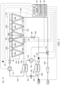
- FIG. 1 is a schematic diagram of an embodiment of a chiller/free cooling system 100.
- the chiller/free cooling system 100 generally receives heated coolant at fluid conduit 114a, cools this coolant, and provides the cooled coolant via fluid conduit 114b.
- the heated coolant may be received from an indoor unit (not shown for clarity and conciseness) that conditions air for delivery to a conditioned space or otherwise provides cooling to an indoor space or an industrial process.
- the conditioned space may be, for example, a room, a house, an office building, a warehouse, or the like.
- the chiller/free cooling system 100 may be, or may be part of, a rooftop unit (RTU) that is positioned on the roof of a building and the conditioned air is delivered to the interior of the building.
- RTU rooftop unit
- portions of the chiller/free cooling system 100 may be located within the building and a portion outside the building.
- the chiller/free cooling system 100 may include other elements that are not shown here for convenience and clarity.
- the chiller/free cooling system 100 may be configured as shown in FIG. 1 or in any other suitable configuration.
- the chiller/free cooling system 100 may include additional components or may omit one or more components shown in FIG. 1 .
- the components present in the system according to the invention are defined in claim 1.
- the dependent claims 2-7 define the components and the system according to preferred embodiments of the invention.
- the chiller/free cooling system 100 includes a compressor 102, a working fluid conduit subsystem 104, a condenser 106, an expansion device 108, an evaporator 110, a coolant pump 112, a coolant conduit subsystem 114a-f, a first set of coils 120, a second set of coils 122, a first valve 124, a second valve 126, a third valve 128, a fourth valve 130, a three-way valve 132, one or more sensors 134, 136, 138, and a controller 140.
- the compressor 102, working fluid conduit subsystem 104, expansion device 108, condenser 106, and evaporator 110 operate to facilitate an expansion-compression cycle of working fluid flowing therethrough.
- the compressor 102 compresses a working fluid (e.g., refrigerant or other fluid) that is provided to the condenser 106 where the working fluid is cooled via heat transfer with the coolant from conduit 114c.
- the cooled working fluid is provided along conduit 104 through expansion device 108 before the working fluid is provided to the evaporator 110.
- heat is transferred from the coolant flowing in conduit 114d to the working fluid, such that the coolant is cooled before being provided to conduit 114b for indoor cooling.
- the coolant may be any appropriate coolant fluid, such as water or a mixture of water and glycol.
- the compressor 102 may be a single-stage or multi-stage compressor. While FIG. 1 includes a single compressor, the system 100 could include multiple compressors connected in parallel.
- a single-stage compressor is generally configured to operate at a constant speed to increase the pressure of the working fluid to keep the working fluid moving along the working-fluid conduit subsystem 104.
- a multi-stage compressor may include multiple compressors configured to operate at a constant speed to increase the pressure of the working fluid to keep the working fluid moving along the working-fluid conduit subsystem 104.
- one or more compressors can be turned on or off to adjust characteristics heat transfer at the condenser 106 and/or evaporator 110.
- the compressor 102 may be configured to operate at multiple speeds or as a variable speed compressor. For example, the compressor 102 may be configured to operate at different predetermined speeds.
- the compressor 102 is in signal communication with the controller 140 using a wired or wireless connection.
- the controller 140 is configured to provide commands or signals to control the operation of the compressor 102.
- the working fluid conduit subsystem 104 facilitates the movement of the working fluid (e.g., a refrigerant) through the expansion compression cycle facilitated by the compressor 102, condenser 106, expansion device 108, and evaporator 110.
- the working fluid may be any acceptable working fluid including, but not limited to, fluorocarbons (e.g. chlorofluorocarbons), ammonia, non-halogenated hydrocarbons (e.g. propane), hydroflurocarbons (e.g. R-410A, R32), or any other suitable type of refrigerant.
- the condenser 106 is generally any heat exchanger, such as a water condenser, located downstream of the compressor 102 and is used to remove heat from the working fluid (e.g., via heat transfer with coolant from conduit 114c).
- the compressed, cooled working fluid flows from the condenser 106 toward the expansion device 108.
- the expansion device 108 is configured to reduce pressure from the working fluid.
- the expansion device 108 is coupled to the working-fluid conduit subsystem 104 downstream of the condenser 106. In this way, the working fluid is delivered to the evaporator 110 and receives heat from coolant from conduit 114d to produce a cooled coolant flow in conduit 114b, which may be provided for cooling of an indoor space, such as a room or building or an industrial process.
- the expansion device 108 may be a valve such as an expansion valve or a flow control valve or any other suitable valve for reducing pressure from the working fluid while, optionally, providing control of the rate of flow of the working fluid.
- the expansion device 108 may be mechanically controlled with an internal regulation system, such that there may be no communication with the controller 140. In other cases, the expansion device 108 may be in communication with the controller 140 (e.g., via wired and/or wireless communication) to receive control signals for opening and/or closing associated valves and/or providing flow measurement signals corresponding to the rate of working fluid flow through the conduit subsystem 104.
- the evaporator 110 is generally any heat exchanger configured to provide heat transfer between working fluid flowing through the evaporator 110 and coolant from conduit 114d.
- the evaporator 110 is fluidically connected to the compressor 102, such that working fluid generally flows from the evaporator 110 to the compressor 102.
- the coolant pump 112 is generally any fluid pump configured to provide a flow of coolant, such as water.
- the coolant pump 112 and coolant conduit subsystem 114a-f facilitates the flow of coolant through the system 100 as illustrated in FIG. 1 and described herein.
- Each of the outdoor coils 116a-e is a heat exchanger (e.g., comprising one or more tubes and/or coils) configured to transfer heat from a coolant flowing therethrough to outdoor air, thereby cooling the coolant.
- the outdoor coils 116a-e are arranged in parallel, such that a first-side inlet/outlet of each coils 116a-e is in fluid communication with first-side coolant conduits 114e,f and a second-side inlet/outlet of each coils 116a-e is in fluid communication with the second-side coolant conduits 114g,h.
- the system 100 may include a fan 118a-e for each or several coils 116a-e.
- the fans 118a-e may be any type of fan or air moving device operable to provide a flow of outdoor air over the coils 116a-e.
- a first valve 124 is located between first-side coolant conduits 114e and 114f, and a second valve 126 is located between second-side coolant conduits 114g and 114h, as illustrated in FIG. 1 , thereby separating the coils 116a-e into a first set 120 of coils 116a,b on one side of the first valve 124 and second valve 126 and a second set 122 of coils 116c-e on the other side of the first valve 124 and second valve 126. While the first valve 124 and second valve 126 are shown between coils 116b and 116c, it should be understood that the first valve 124 and second valve 126a may be located in between any pair of adjacent coils 116a-e.
- the system 100 include multiple first and second valves 124, 126 between multiple pairs of adjacent coils 116a-e, for example, as illustrated in FIG. 5 and described in greater detail below.
- a third valve 128 is positioned to regulate the flow of coolant from the second-side coolant conduit 114h toward the evaporator 110, as illustrated in FIG. 1 .
- a fourth valve 130 is positioned to regulate the flow of coolant from the first-side coolant conduit 114g toward the condenser 106.
- a three-way valve 132 is in fluid communication with coolant conduit 114a, 114f, and coolant conduit 114d as illustrated in FIG. 1 .
- the various valves 124, 126, 128, 130, and 132 are generally operated (e.g., opened and/or closed) by the controller 140 in order to achieve a desired coolant flow to facilitate cooling of the coolant using refrigerant-based cooling (see high temperature mode configuration of FIG.
- the system 100 may be further coupled to a heat recovery unit, which may further facilitate cooling of the coolant flowing through the conduit subsystem 114a-f (see examples of FIGS. 6 and 7 ).
- the system 100 may include one or more sensors 134, 136, 138 in signal communication with the controller 140.
- Sensors 134 may be any suitable type of sensor for measuring outdoor air temperature and/or other properties of the outdoor environment.
- Sensors 136 and 138 may be positioned and configured to measure a temperature of coolant provided to evaporator 110 and a temperature of coolant output from the evaporator 110, respectively, as illustrated in FIG. 1 .
- Information from the sensors 134, 136, 138 may be provide to the controller 140 as temperature measurements 144.
- Temperature measurements 144 may include an outdoor temperature, a temperature of coolant at the evaporator 110 inlet, and/or a temperature of coolant at the evaporator 110 outlet.
- outdoor temperature may also or alternatively be determined based on weather information (e.g., a weather forecast provided to the controller 140).
- the controller 140 generally receives information from sensors 134, 136, and/or 138 and uses this information to operate the system 100 according to predefined control rules 146.
- the control rules 146 include any instructions, logic, and/or code for adjusting operation of the compressor 106, coolant pump 112, expansion valve 108, and/or valves 124, 126, 128, 130, 132 based at least in part on a measured temperature 144.
- operation of the valves 124, 126, 128, 130, 132 may be determined based on comparison of a measured temperature 144 of outdoor air (e.g., from sensor 134) to a temperature setpoint 142.
- the temperature setpoint 142 may be a target temperature for cooling an indoor space using the cooled coolant provided via conduit 114b.
- the controller 140 is described in greater detail below with respect to FIG. 12 .
- the controller 140 may use control rules 146 for operating in a high temperature mode by closing valve 128 and adjusting the three-way valve 132 to allow coolant flow from input line 114a to conduit 114d and prevent flow from conduit 114a to conduit 114f (see FIG. 2 and corresponding description below).
- the controller 140 may use control rules 146 for operating in a low temperature mode by closing valve 130 and adjusting the three-way valve 132 to allow flow of coolant from conduit 114a to conduit 114f and prevent flow of coolant from conduit 114a to conduit 114d (see FIG. 3 and corresponding description below).
- the controller 140 may use control rules 146 for operating in an intermediate temperature mode by closing valves 124 and 126 and adjusting the three-way valve 132 to allow flow of coolant from conduit 114a to conduit 114f and prevent flow of coolant from conduit 114a to conduit 114d (see FIGS. 4 and 5 and corresponding description below).
- the control rules 146 include instructions for adjusting valves 124, 126, 128, 130, 132, such that coolant may be cooled using fluid received from the heat recovery unit alone or in combination with the refrigerant-based cooling and/or free cooling, as illustrated in FIGS. 6 and 7 .
- Connections between various components of the system 100 may be wired and/or wireless.
- conventional cable and contacts may be used to couple the controller 140 to the various components of the system 100, including the compressor 102, coolant pump 112, expansion valve 108, and valves 124, 126, 128, 130, 132, and sensors 134, 136, 138.
- a wireless connection is employed to provide at least some of the connections between components of the system 100 such as, for example, a connection between controller 140 and the sensors 134, 136, 138 of system 100.
- a data bus couples various components of the system 100 together such that data is communicated therebetween.
- the data bus may include, for example, any combination of hardware, software embedded in a computer readable medium, or encoded logic incorporated in hardware or otherwise stored (e.g., firmware) to couple components of system 100 to each other.
- the data bus may include an Accelerated Graphics Port (AGP) or other graphics bus, a Controller Area Network (CAN) bus, a front-side bus (FSB), a HYPERTRANSPORT (HT) interconnect, an INFINIBAND interconnect, a low-pin-count (LPC) bus, a memory bus, a Micro Channel Architecture (MCA) bus, a Peripheral Component Interconnect (PCI) bus, a PCI-Express (PCI-X) bus, a serial advanced technology attachment (SATA) bus, a Video Electronics Standards Association local (VLB) bus, or any other suitable bus or a combination of two or more of these.
- the data bus may include any number, type, or configuration of data buses
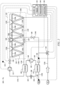
- FIG. 2 illustrates an example operation of system 100 in a high ambient temperature mode.
- the controller 140 may receive an outdoor temperature measurement 144 (e.g., from sensor 134 and/or weather information) and an indoor setpoint temperature 142 (e.g., from an indoor system that receives cooled coolant from conduit 114b). Based on a comparison of the outdoor temperature measurement 144 to the indoor setpoint temperature 142, the controller 140 determines that the system 100 should operate in a high temperature mode.
- an outdoor temperature measurement 144 e.g., from sensor 134 and/or weather information
- an indoor setpoint temperature 142 e.g., from an indoor system that receives cooled coolant from conduit 114b
- the controller 140 may determine a difference between the outdoor air temperature 144 (T outdoor ) and the setpoint temperature 142 (T setpoint ) and determine whether the difference (T outdoor - T setpoint ) is greater than a predefined threshold value (e.g., a threshold value 1214 of FIG. 12 ).
- the controller 140 may receive a temperature measurement 144 of coolant (e.g. entering evaporator 110 from sensor 136 and/or exiting evaporator 110 from sensor 138), and the coolant temperature 144 may be compared to the temperature setpoint 142, similarly to as described above, to determine that the system 100 should operate in the high temperature mode. Further examples of determining the operating mode of the system 100 are described with respect to step 804 of FIG. 8 below.
- the controller 140 After determining that the system 100 should operate in the high temperature operating mode, the controller 140 adjusts the valves 124, 126, 128, 130, and 132 as illustrated in FIG. 2 .
- closed lines correspond to open valves
- dashed lines correspond to closed valves.
- closed lines in conduits 104 and 114a-f correspond to conduits 104, 114a-f in which there is a flow of fluid (i.e., working fluid or coolant) and dashed lines correspond to conduits 104, 114a-f without flow of fluid.
- the controller 140 may cause the coolant pump 112 to operate to provide a flow of coolant through conduits 114c,e,f,h,g and the coils 116a-e.
- the controller 140 causes the first valve 124 to be in an open position such that flow of coolant is allowed between coolant conduit 114e and 114f.
- the controller 140 also causes the second valve 126 to be in the open position such that flow of coolant is allowed between coolant conduit 114g and coolant conduit 114h.
- the controller 140 causes the third valve 128 to be in a closed position such that flow of coolant is prevented between coolant conduit 114h and coolant conduit 114d.
- the controller 140 causes the fourth valve 130 to be in an open position such that flow of coolant is allowed between coolant conduit 114g and the condenser 106.
- the controller 140 causes the three-way valve 132 to be in a position such that flow of coolant is allowed between coolant input conduit 114a and coolant conduit 114d and prevented between the input conduit 114a and coolant conduit 114f.
- the controller 140 may also provide a control signal to the compressor 102 to cause the compressor 102 to operate. Accordingly, in the high temperature operating mode, the condenser 106 receives coolant cooled by the coils 116a-e and transfers heat from the working fluid to the cooled coolant, thereby cooling the working fluid.
- the evaporator 110 receives working fluid cooled by the condenser 106 and transfers heat from the flow of the coolant received from input conduit 114a and passed to the evaporator 110 via three-way valve 132 to the cooled working fluid, thereby cooling the coolant before it is returned to the indoor system via conduit 114b.
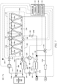
- FIG. 3 illustrates an example operation of system 100 in a low ambient temperature mode.
- the controller 140 receive an outdoor temperature measurement 144 (e.g., from sensor 134 and/or weather information) and an indoor setpoint temperature 142 (e.g., from an indoor system that receives cooled coolant from conduit 114b). Based on a comparison of the outdoor temperature measurement 144 to the indoor setpoint temperature 142, the controller 140 determines that the system 100 should operate in a low temperature mode.
- an outdoor temperature measurement 144 e.g., from sensor 134 and/or weather information
- an indoor setpoint temperature 142 e.g., from an indoor system that receives cooled coolant from conduit 114b
- the controller 140 may determine a difference between the setpoint temperature 142 (T setpoint ) and the outdoor air temperature 144 (T outdoor ) and determine whether the difference (T setpoint - T outdoor ) is greater than a predefined threshold value (e.g., a threshold value 1214 of FIG. 12 ).
- the controller 140 may receive a temperature measurement 144 of coolant (e.g. entering evaporator 110 from sensor 136 and/or exiting evaporator 110 from sensor 138) and use this coolant temperature 144 to determine the operating mode of the system 100.
- the controller 140 may determine that the system 100 should operate in the low temperature operating mode by determining that the coolant temperature 144 is less than a threshold value (e.g., a threshold value 1214 of FIG. 12 ). Further examples of determining the operating mode of the system 100 are described with respect to step 804 of FIG. 8 below.
- a threshold value e.g., a threshold value 1214 of FIG. 12
- the controller 140 adjusts the valves 124, 126, 128, 130, and 132 as illustrated in FIG. 3 .
- closed lines correspond to open valves
- dashed lines correspond to closed valves.
- closed lines in conduits 104 and 114a-f correspond to conduits 104, 114a-f in which there is a flow of fluid (i.e., working fluid or coolant) and dashed lines correspond to conduits 104, 114a-f without flow of fluid.
- the controller 140 causes the first valve 124 to be in an open position such that flow of coolant is allowed between coolant conduit 114e and coolant conduit 114f.
- the controller 140 also causes the second valve 126 to be in the open position such that flow of coolant is allowed between coolant conduit 114g and coolant conduit 114h.
- the controller 140 causes the third valve 128 to be in an open position such that flow of coolant is allowed between coolant conduit 114h and coolant conduit 114d.
- the controller 140 causes the fourth valve 130 to be in a closed position such that flow of coolant is prevented between coolant conduit 114g and the condenser 106.
- the controller 140 causes the three-way valve 132 to be in a position such that flow of coolant is prevented between the coolant input conduit 114a and coolant conduit 114d and allowed between the input conduit 114a and coolant conduit 114f. As such, coolant does not transfer heat with the condenser 106, and cooling of the coolant is provided through heat transfer with outdoor air at coils 116a-e.
- the controller 140 may also provide a control signal to the compressor 102 to cause the compressor 102 to turn off. In some embodiments, the controller 140 may also or alternatively provide a control signal instructing coolant pump 112 to turn off. Accordingly, in the low temperature operating mode, energy consumption is decreased by not operating compressor 102 and/or coolant pump 112. The working fluid that is cooled via heat transfer with cool outdoor air at coils 116a-e is returned to the indoor cooling system via conduit 114b.
- FIG. 4 illustrates an example operation of system 100 in an intermediate ambient temperature mode.
- the controller 140 receive an outdoor temperature measurement 144 (e.g., from sensor 134 and/or weather information) and an indoor setpoint temperature 142 (e.g., from an indoor system that receives cooled coolant from conduit 114b). Based on a comparison of the outdoor temperature measurement 144 to the indoor setpoint temperature 142, the controller 140 determines that the system 100 should operate in an intermediate temperature mode. For example, the controller 140 may determine that the measured temperature 144 of outdoor air is not greater than a threshold amount (e.g., a threshold value 1214 of FIG. 12 ) above or a threshold amount below the temperature setpoint 142. In such cases, the controller 140 may determine to operate the system 100 in the intermediate temperature mode. Further examples of determining the operating mode of the system 100 are described with respect to step 804 of FIG. 8 below.
- a threshold amount e.g., a threshold value 1214 of FIG. 12
- the controller 140 adjusts the valves 124, 126, 128, 130, and 132 as illustrated in FIG. 4 .
- closed lines correspond to open valves
- dashed lines correspond to closed valves.
- closed lines in conduits 104 and 114a-f correspond to conduits 104, 114a-f in which there is a flow of fluid (i.e., working fluid or coolant) and dashed lines correspond to conduits 104, 114a-f without flow of fluid.
- the controller 140 causes the first valve 124 to be in a closed position such that flow of coolant is prevented between coolant conduit 114e and coolant conduit 114f.
- the controller 140 also causes the second valve 126 to be in a closed position such that flow of coolant is prevented between coolant conduit 114g and coolant conduit 114h. Closing the first valve 124 and the second valve 126 segregates coils 116a,b into the first coil set 120 and coils 116c-e into the second coil set 122.
- the first coil set 120 is used for refrigerant-based cooling (i.e., using heat transfer with condenser 106), while the coil set 122 is used for free cooling (e.g., using heat transfer with cool outdoor air).
- the system 100 may include additional first valves 124 and second valves 126 positioned between different adjacent pairs of coils 116a-e, such that the controller 140 may select the number of coils 116a-e to include in the first coil set 120 for refrigerant-based cooling and in the coil set 122 for free cooling (see FIG. 5 and corresponding description below).
- the controller 140 also causes the third valve 128 to be in an open position such that flow of coolant is allowed between coolant conduit 114h and coolant conduit 114d.
- the controller 140 causes the fourth valve 130 to be in an open position such that flow of coolant is allowed between coolant conduit 114g and the condenser 106.
- the controller 140 causes the three-way valve 132 to be in a position such that flow of coolant is prevented between the coolant input conduit 114a and coolant conduit 114d and allowed between the input conduit 114a and coolant conduit 114f.
- the first coil set 120 is used for refrigerant-based cooling (i.e., using heat transfer with condenser 106), while the coil set 122 is used for free cooling (e.g., using heat transfer with at least moderately cool outdoor air).
- coolant from coil set 120 transfers heat with the condenser 106 in order to facilitate cooling using evaporator 110.
- coolant is also cooled via free cooling using coil set 122 via heat transfer with outdoor air. Accordingly, less energy may be consumed to operate coolant pump 112 and/or compressor 102, since at least a portion of cooling is achieved using free cooling.
- FIG. 5 illustrates an example system 500 that is alternative embodiment of the system 100 in which the number of coils 116a-e used for refrigerant-based cooling and free cooling can be intelligently adjusted.
- the system 500 includes the same components of system and a plurality of first valves 124a-d and second valves 126a-d.
- the multiple valves allow the system 100 to operate in various "split" intermediate temperature configurations such that a different number of the coils 116a-e can be used for refrigerant-based cooling (i.e., coils 116a-e to left of whichever valves 124a-d, 126a-d are closed) while the remaining coils 116a-e are used for free cooling (i.e., the coils 116a-e to the right of whichever valves 124a-d, 126a-d are closed).
- the controller 140 determines that the system 500 should operate in the intermediate temperature operating mode (e.g., as described above and below with respect to FIG.
- the controller 140 of system 500 may further determine which one of the first valves 124a-d and which one of the second valves 126a-d to close. For instance, if the outdoor temperature 144 is not greater than a threshold amount above or below the temperature setpoint 142 but the outdoor temperature 144 is relatively cold, more of the coils 116a-e may be used for free cooling.
- the controller 140 may determine which valves 124a-d and 126a-d to close based on a comparison of the outdoor temperature 144 and/or the setpoint temperature 142 to a predefined temperature associated with effective free cooling operation (e.g., a threshold temperature 1214 of FIG. 12 ). If the outdoor temperature 144 is nearer the predefined temperature, then more of the coils 116a-e may be used for free cooling. As an example, if the outdoor temperature 144 is within a first threshold range above the predefined temperature, the controller 140 may close valves 124a and 126a, such that coils 116b-e are used for free cooling.
- a predefined temperature associated with effective free cooling operation e.g., a threshold temperature 1214 of FIG. 12 .
- the controller 140 may close valves 124b and 126b, such that coils 116c-e are used for free cooling.
- the controller 140 may close valves 124c and 126c, such that coils 116d,e are used for free cooling.
- the controller 140 may close valves 124d and 126d, such that only coil 116e is used for free cooling. Valves 128, 130, and 132 are positioned/configured as described with respect to FIG. 4 above.
- FIG. 6 illustrates an example system 600 that is an alternative embodiment of the system 100 (or system 500) in which the system 600 is coupled to a heat recovery unit 602.
- the heat recovery unit 602 may be any system configured to recover heat to provide heating indoors (e.g., to a portion of an indoor space).
- the heat recovery unit 602 generally outputs a flow of cooled coolant and receives a higher temperature coolant following heat transfer at condenser 106.
- the system 600 includes the same components of system 100 (or system 500) along with the heat recovery unit 602, additional fluid conduit 604, an additional three-way valve 606, and a temperature sensor 608 configured to measure the temperature of the heated coolant supplied to the heat recovery unit 206. Measurements from the temperature sensor 608 are provided to the controller 140 as temperature measurements 144.
- the controller 140 is generally configured to use control rules 146 to operate the three-way valve 606 to allow receipt of coolant (e.g., water or any other appropriate coolant) from the heat recovery unit 602 at condenser 106, cooling of working fluid by the received coolant, and return of the resulting heated coolant back to the heat recovery unit 602.
- coolant e.g., water or any other appropriate coolant
- a heat exchanger may be placed at the position of valve 606. Coolant from the recovery unit 602 may transfer heat with the heated coolant output by condenser 106 and provided as heated coolant back to the heat recovery unit 602.
- the controller 140 may use measured temperatures 144 and/or the setpoint 142 to determine whether the cooling of working fluid in conduit subsystem 104 and of coolant provided to the indoor system via coolant conduit 114b should be provided through heat exchange with the heat recovery unit 602 alone (see configuration of FIG. 6 ) or in combination with refrigerant-based cooling and/or free cooling (see configuration of FIG. 7 ). For example, if the controller 140 determines that there is a request for heat recovery (e.g., at a requested coolant temperature) from the heat recovery unit 602 and that the temperature 144 of coolant provided to the heat recover unit 602 is less than or equal to a threshold value (e.g., a threshold value 1214 of FIG. 12 corresponding to the requested coolant temperature value), the controller 140 may determine that cooling from the heat recovery unit 602 alone is appropriate.
- a threshold value e.g., a threshold value 1214 of FIG. 12 corresponding to the requested coolant temperature value
- the controller 140 causes the valves 124, 126, 128, and 130 to be in closed position such that flow of coolant is prevented through these valves 124, 126, 128, 130, as illustrated in FIG. 6 .
- the controller 140 causes the three-way valve 132 to be in a position such that flow of coolant is allowed between coolant input conduit 114a and coolant conduit 114d and prevented between input conduit 114a and coolant conduit 114f.
- the controller 140 also causes the added three-way valve 606 to be in a position such that fluid flow is allowed between inlet conduit 604 and outlet conduit 604 (returning to the heat recovery unit 602) but prevented between inlet conduit 604 and coolant conduit 114e.
- the controller 140 may turn on the compressor 102 and turn off coolant pump 112. During operation in the configuration of FIG. 6 , power consumption may be reduced because coolant pump 112 may not be operating (i.e., may be turned off). Additionally, the heat recovered by the heat recovery unit 602 may provide further energy savings (e.g., because an active power source, such as a resistive heater or gas heater, is not needed or is needed to a lesser extent).
- an active power source such as a resistive heater or gas heater
- the controller 140 may determine that some of the heated coolant should be directed through coolant conduit 114e to prevent overheating of the heat recovery unit 602.
- FIG. 7 illustrates a possible configuration for this example scenario in which the coil set 120 are used to provide supplemental cooling. As shown in FIG. 7 , the controller 140 causes the first valve 124 to be in a closed position such that flow of coolant is prevented between coolant conduit 114e and coolant conduit 114f.
- the controller 140 also causes the second valve 126 to be in a closed position such that flow of coolant is prevented between coolant conduit 114g and coolant conduit 114h.
- the controller 140 causes the third valve 128 to be in an open position such that flow of coolant is allowed between coolant conduit 114h and coolant conduit 114d.
- the controller causes the fourth valve 130 to be in an open position such that flow of coolant is allowed between coolant conduit 114g and the condenser 106.
- the controller 140 causes the three-way valve 132 to be in a position such that flow of coolant is allowed between the coolant input conduit 114a and the coolant conduit 114d and prevented between the input conduit 114a and the coolant conduit 114f.
- the controller 140 also causes the added three-way valve 606 to be in a position such that fluid flow is allowed between inlet conduit 604 and both coolant conduit 114e and outlet conduit 604 (returning to the heat recovery unit 602).
- the controller 140 may turn on the compressor 106 and coolant pump 112 to operate as illustrated in FIG. 7 .
- a method of operating a combined chiller/free cooling system according to the invention is defined in claim 8.
- the dependent claims 9-13 define preferred embodiments of the method according to the invention.
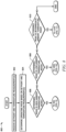
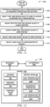
- FIG. 8 is a flowchart of an example method 800 of operating the systems 100, 500, and/or 600 described in any of FIGS. 1-7 .
- example method 800 is described with respect to system 100. However, the method 800 may be performed using system 500 of FIG. 5 and system 600 of FIGS. 6 and 7 .
- Example method 800 includes processes for determining an appropriate operating mode of the system 100 and is linked to example method 900 for operating in a high temperature mode ( FIG.9 ), example method 1000 for operating in a low temperature mode ( FIG. 10 ), and example method 1100 for operating in an intermediate temperature mode ( FIG. 11 ).
- Method 800 may begin at step 802 where the controller 140 receives the setpoint temperature 142 and temperature measurements 144.
- the temperature setpoint 142 is generally a target temperature of an indoor space that is cooled at least in part using the cooled coolant provided via coolant conduit 114b of system 100.
- the temperature measurements 144 may include a measurement of outdoor temperature (e.g., from sensor 134 and/or available weather information) and/or measurement(s) of coolant temperature (e.g., from sensors 136, 138, 608).
- the controller 140 determines a mode in which to operate the system 100 (e.g., based on control rules 146) using the temperature setpoint 142 and the temperature measurements 144. For example, the controller 140 may compare the temperature setpoint 142 to the outdoor temperature 144. For instance, if a measured temperature 144 of outdoor air is greater than a threshold amount above the temperature setpoint 142, the controller 140 may determine that the system 100 should operate in a high temperature mode. If the measured temperature 144 of outdoor air is greater than a threshold amount below the temperature setpoint 142, the controller 140 may determine that the system should operate in the low temperature mode.
- the controller 140 may determine the system 100 should operate in an intermediate temperature mode. As another example, the controller 140 may compare the temperature setpoint 142 to a coolant temperature 144 measured by sensors 136 and/or 138. For instance, If the system 100 is currently operating in high temperature mode (see FIG. 2 ) and the resulting coolant temperature 144 measured at sensor 138 is colder than necessary to achieve the setpoint temperature 142 (e.g., if the coolant temperature 144 is less than a threshold amount below the setpoint temperature 142), the controller 140 may determine that partial free cooling operation may be appropriate (e.g., in the intermediate temperature mode). This may improve operating efficiency (e.g., decrease energy consumption) while protecting against undesirable freezing of coolant.
- partial free cooling operation may be appropriate (e.g., in the intermediate temperature mode). This may improve operating efficiency (e.g., decrease energy consumption) while protecting against undesirable freezing of coolant.
- step 806 if the controller 140 determines that the system 100 should operate in the high temperature mode, the controller 140 proceeds to step 902 of the example method 900 shown in FIG. 9 .
- the controller 140 determines if heat recovery is desired at step 902. For example, the controller 140 may determine if a request for heat recovery is received from the heat recover unit 602 of FIG. 6 . Heat recovery may be requested, for example, if heating is desired for at least a portion of an indoor space.
- the controller 140 proceeds to steps 904, 906, and 908 to configure the system 100 as illustrated in FIG. 2 and described above.
- the controller 140 causes the first valve 124, second valve 126, and fourth valve 130 to be adjusted to an open position.
- the controller 140 causes the third valve 128 to be adjusted to a closed position.
- the controller 140 adjusts the three-way valve 132 to the configuration illustrated in FIG. 2 , such that flow of coolant is allowed between coolant input conduit 114a and coolant conduit 114d and prevented between the input conduit 114a and the coolant conduit 114f.
- step 910 determines whether coolant is heated beyond what is requested by the heat recovery unit 602. For example, the controller 140 may determine whether the temperature 144 of coolant provided to the heat recovery unit 602 (e.g., as measured by sensor 608 of FIG. 6 ) is less than a threshold temperature, as described above with respect to FIGS. 6 and 7 . If the coolant temperature 144 is less than the threshold temperature, then additional cooling is not needed at step 910. However, if the coolant temperature is not less than the threshold temperature, then additional cooling is needed.
- the controller 140 may proceed to adjust configuration of the system according to FIG. 6 at steps 912, 914, and 908.
- the controller 140 causes the additional valve 606 to be adjusted as illustrated in FIG. 6 , such that flow is allowed between inlet conduit 604 and outlet conduit 604 (returning to the heat recovery unit 602) but prevented between inlet conduit 604 and coolant conduit 114e.
- the controller 140 adjusts the first, second, third and fourth valves 124, 126, 128, 130 to closed positions.
- the controller 140 adjusts the three-way valve 132 to the position illustrated in FIG. 6 , such that flow of coolant is allowed between the coolant input conduit 114a and the coolant conduit 114d and prevented between the input conduit 114a and the coolant conduit 114f.
- the controller 140 may proceed to adjust configuration of the system according to FIG. 7 at steps 916, 918, 920, and 908.
- the controller 140 causes the additional valve 606 to be adjusted as illustrated in FIG. 7 , such that flow is allowed between inlet conduit 604 and both coolant conduit 114e and outlet conduit 604 (returning to the heat recovery unit 602).
- the controller 140 adjusts the first, second, and third valves 124, 126, 128 to closed positions.
- the controller 140 adjusts the fourth valve 130 to an open position.
- the controller 140 may also turn on the coolant pump 112.
- the controller 140 adjusts the three-way valve 132 to the position illustrated in FIG. 7 , such that flow of coolant is allowed between the coolant input conduit 114a and the coolant conduit 114d and prevented between the input conduit 114a and the coolant conduit 114f.
- the controller 140 may determine if the full free cooling capacity of the system 100 is needed at step 1002. For example, the controller 140 may determine what coolant temperature 144 (e.g., measured by sensor 136) is achieved if all coils 116a-e are used for free cooling. If this temperature 144 is less than a threshold value (e.g., a value which may cause freezing in coolant conduit 114a-f), then the full free cooling capacity is not desired at step 1002. Otherwise, the full free cooling capacity is desired using all coils 116a-e.
- a threshold value e.g., a value which may cause freezing in coolant conduit 114a-f
- the controller proceeds to adjust the system 100 according to the configuration of FIG. 3 at steps 1004, 1006, 1008, and 1010.
- the controller 140 causes the first, second, and third valves 124, 126, 128 to be in an open position.
- the controller 140 causes the fourth valve 130 to be in a closed position.
- the controller 140 turns off the compressor 102 and the coolant pump 112 (e.g., if these components were previously turned on).
- the controller 140 adjusts the three-way valve 132 as illustrated in FIG. 3 , such that flow of coolant is prevented between the coolant input conduit 114a and coolant conduit 114d and allowed between the input conduit 114a and coolant conduit 114f.
- step 1012 determines a number of coils 116a-e to use for free cooling (e.g., for the system 500 of FIG. 5 with multiple first valves 124a-d and multiple second valves 16a-d).
- the controller 140 may determine a number of coils 116a-e that will bring the coolant temperature measured by sensor 136 and/or 138 to a value that is closest to a threshold value without falling below the threshold vale.
- the threshold value may be a threshold 1214 of FIG. 12 selected to prevent freezing of the coolant.
- the controller 140 causes the third valve 128 to be in an open position.
- the controller 140 causes the first valve 124 (e.g., the valve 124a-d determined at step 1012), the second valve 126 (e.g., the valve 126a-d determined at step 1012), and the fourth valve 130 to be in a closed position.
- the controller 140 then proceeds to steps 1008 and 1010, which are described above.
- step 810 if the controller 140 determines at step 810 that the system 100 should operate in the intermediate temperature mode, the controller 140 proceeds to step 1102 of the example method 1100 shown in FIG. 11 .
- the controller 140 may determine how to split coolant between refrigerant-based cooling in coil set 120 and free cooling in coil set 122.
- the number of coils 116a-e to use for refrigerant-based cooling and free cooling may determine the number of coils 116a-e to use for refrigerant-based cooling and free cooling based on a comparison of the outdoor temperature 144 and/or the setpoint temperature 142 to a predefined temperature associated with effective free cooling operation (e.g., a threshold temperature 1214 of FIG. 12 ), as described in greater detail above with respect to FIG. 5 .
- a predefined temperature associated with effective free cooling operation e.g., a threshold temperature 1214 of FIG. 12
- the controller 140 determines which first valve 124a-d and which second valve 126a-d to close to achieve the split determined at step 1102. For example, the controller 140 determines that valves 124b and 126b are closed to achieve a split with coils 116a,b used for refrigerant-based cooling and coils 116c-e used for free cooling. For a system without multiple first valves 124a-d and multiple second valves 126a-d, such as system 100 of FIGS. 1-4 , steps 1102 and 1104 may not be performed.
- the controller 140 causes the determined first and second valves 124a-d and 126a-d to be closed, and, at step 1108, the controller 140 causes the remaining first and second valves 124a-d and 126a-d to be open. For instance, if the controller 140 determines that valves 124b and 126b should be closed at step 1104, then valves 124b and 126b are closed at step 1106, while valves 124a,c-d and valves 126a,c-d are opened at step 1108. For a system without multiple first valves 124a-d and multiple second valves 126a-d, such as system 100 of FIGS. 1-4 , the controller 140 closes the first and second valves 124 and 126.
- the controller 140 adjusts the third valve 128 and fourth valve 130 to an open position.
- the controller 140 adjusts the three-ways valve to the position illustrated in FIG. 4 , such that flow of coolant is prevented between the coolant input conduit 114a and coolant conduit 114d and allowed between the input conduit 114a and coolant conduit 114f.
- FIG. 12 is a schematic diagram of an embodiment of a the controller 140 of FIGS. 1-7 .
- the controller 140 according to the invention is described in claim 14 and includes a processor 1202, a memory 1204, and an input/output (I/O) interface 1206.
- the processor 1202 comprises one or more processors operably coupled to the memory 1204.
- the processor 1202 is any electronic circuitry including, but not limited to, state machines, one or more central processing unit (CPU) chips, logic units, cores (e.g. a multi-core processor), field-programmable gate array (FPGAs), application specific integrated circuits (ASICs), or digital signal processors (DSPs) that communicatively couples to memory 1204 and controls the operation of systems 100, 500, 600.
- the processor 1202 may be a programmable logic device, a microcontroller, a microprocessor, or any suitable combination of the preceding.
- the processor 1202 is communicatively coupled to and in signal communication with the memory 1204.
- the one or more processors are configured to process data and may be implemented in hardware or software.
- the processor 1202 may be 8-bit, 16-bit, 32-bit, 64-bit or of any other suitable architecture.
- the processor 1202 may include an arithmetic logic unit (ALU) for performing arithmetic and logic operations, processor registers that supply operands to the ALU and store the results of ALU operations, and a control unit that fetches instructions from memory 1204 and executes them by directing the coordinated operations of the ALU, registers, and other components.
- the processor may include other hardware and software that operates to process information, control the system 100, 500, 600, and perform any of the functions described herein (e.g., with respect to FIGS 1-11 ).
- the processor 1202 is not limited to a single processing device and may encompass multiple processing devices.
- the controller 140 is not limited to a single controller but may encompass multiple controllers.
- the memory 1204 comprises one or more disks, tape drives, or solid-state drives, and may be used as an over-flow data storage device, to store programs when such programs are selected for execution, and to store instructions and data that are read during program execution.
- the memory 1204 may be volatile or non-volatile and may comprise ROM, RAM, ternary content-addressable memory (TCAM), dynamic random-access memory (DRAM), and static random-access memory (SRAM).
- the memory 1204 is operable to store temperature setpoint 142, measured temperatures 144, control rules 146, threshold values 1214, and any other data or instructions.
- the control rules 146 include high temperature mode instructions 1208, low temperature mode instructions 1210, and intermediate temperature instructions 1212.
- Each set of instructions 1208, 1210, 1212 includes any suitable set of logic, rules, or code operable to execute the operations described above with respect to FIGS. 1-11 .
- the I/O interface 1206 is configured to communicate data and signals with other devices.
- the I/O interface 1206 may be configured to communicate electrical signals with the components of the systems 100, 500, 600, as described above and illustrated in FIGS. 1-7 .
- the I/O interface may receive, for example, setpoint temperature 142, temperature measurements 144, environmental conditions, and the like and send electrical signals to the valves 124, 126, 128, 130, 132, 606, compressor 102, coolant pump 112, and any other appropriate system components.
- the I/O interface 1206 may use any suitable type of communication protocol to communicate with various components of the systems 100, 500, 600.
- the I/O interface 1206 may be configured to transmit pulse width modulation (PWM) signals.
- PWM pulse width modulation
- the I/O interface 1206 may use any other suitable type of signals to control components as would be appreciated by one of ordinary skill in the art.
- the I/O interface 1206 may comprise ports or terminals for establishing signal communications between the controller 140 and other devices.
- the I/O interface 1206 may be configured to enable wire and/or wireless communications.
Landscapes
- Engineering & Computer Science (AREA)
- Mechanical Engineering (AREA)
- General Engineering & Computer Science (AREA)
- Physics & Mathematics (AREA)
- Thermal Sciences (AREA)
- Chemical & Material Sciences (AREA)
- Combustion & Propulsion (AREA)
- Air Conditioning Control Device (AREA)
- Other Air-Conditioning Systems (AREA)
Claims (14)
- System (100), umfassend:einen ersten Satz von Kühlschlangen (120), die dazu ausgelegt sind:Kühlmittel aus einer ersten Kühlmittelleitung (114e) zu empfangen;Wärme aus dem Kühlmittel an die Außenluft zu übertragen; unddas Kühlmittel zu einer zweiten Kühlmittelleitung (114g) zu leiten;einen zweiten Satz von Kühlschlangen (122), die dazu ausgelegt sind:Kühlmittel aus einer dritten Kühlmittelleitung (114f) zu empfangen;Wärme aus dem Kühlmittel an die Außenluft zu übertragen; unddas Kühlmittel zu einer vierten Kühlmittelleitung (114h) zu leiten;ein erstes Ventil (124), das dazu angeordnet und ausgelegt ist, den Kühlmittelfluss zwischen der ersten Kühlmittelleitung (114e) und der dritten Kühlmittelleitung (114f) zu regeln;ein zweites Ventil (126), das dazu angeordnet und ausgelegt ist, den Kühlmittelfluss zwischen der zweiten Kühlmittelleitung (114g) und der vierten Kühlmittelleitung (114h) zu regeln;ein drittes Ventil (128), das dazu angeordnet und ausgelegt ist, den Kühlmittelfluss zwischen der vierten Kühlmittelleitung (114h) und einer fünften Kühlmittelleitung (114d) zu regeln, wobei die fünfte Kühlmittelleitung (114d) mit einem Wasserverdampfer (110) und einem Dreiwegeventil (132) gekoppelt ist;das Dreiwegeventil (132), das dazu ausgelegt ist, den Kühlmittelfluss zwischen der fünften Kühlmittelleitung (114d), der dritten Kühlmittelleitung (114f) und einer Kühlmitteleingangsleitung (114a) zu regeln;ein viertes Ventil (130), das dazu angeordnet und ausgelegt ist, den Kühlmittelfluss zwischen der ersten Kühlmittelleitung (114e) und einem Wasserkondensator (106) zu regeln; undeine Steuereinrichtung (140), die mit dem ersten Ventil (124), dem zweiten Ventil (126), dem dritten Ventil (128), dem vierten Ventil (130) und dem Dreiwegeventil (132) gekoppelt ist, wobei die Steuereinrichtung (140) einen Prozessor (1202) umfasst, der dazu ausgelegt ist:eine Außentemperatur und eine Sollinnentemperatur zu empfangen;basierend auf einem Vergleich der Außentemperatur mit der Sollinnentemperatur zu bestimmen, ob das System (100) in einem Hochtemperatur-Betriebsmodus arbeiten soll;nach dem Bestimmen, dass das System (100) in dem Hochtemperatur-Betriebsmodus arbeiten soll:das erste Ventil (124) in eine geöffnete Stellung zu bringen, sodass ein Kühlmittelfluss zwischen der ersten Kühlmittelleitung (114e) und der dritten Kühlmittelleitung (114f) möglich ist;das zweite Ventil (126) in die geöffnete Stellung zu bringen, sodass ein Kühlmittelfluss zwischen der zweiten Kühlmittelleitung (114g) und der vierten Kühlmittelleitung (114h) möglich ist;das dritte Ventil (128) in eine geschlossene Stellung zu bringen, sodass der Kühlmittelfluss zwischen der vierten Kühlmittelleitung (114h) und der fünften Kühlmittelleitung (114d) verhindert wird;das vierte Ventil (130) in die geöffnete Stellung zu bringen, sodass ein Kühlmittelfluss zwischen der zweiten Kühlmittelleitung (114g) und dem Wasserkondensator (106) möglich ist; unddas Dreiwegeventil (132) in eine Stellung zu bringen, in der ein Kühlmittelfluss:zwischen dem Kühlmitteleingang und der fünften Kühlmittelleitung (114d) möglich ist; undzwischen dem Kühlmitteleingang und der dritten Kühlmittelleitung (114f) verhindert wird.
- System (100) gemäß Anspruch 1, wobei der Wasserkondensator (106) dazu ausgelegt ist:Kühlmittel zu empfangen, das durch den ersten Satz von Kühlschlangen (120) und den zweiten Satz von Kühlschlangen (122) gekühlt wurde; undWärme aus dem Kältemittel auf das gekühlte Kühlmittel zu übertragen und dadurch das Kältemittel zu kühlen.
- System (100) gemäß Anspruch 1, wobei der Wasserverdampfer (110) dazu ausgelegt ist:das durch den Wasserkondensator (106) gekühlte Kältemittel zu empfangen; undWärme aus dem Kühlmittel, das aus der fünften Kühlmittelleitung (114d) empfangen wurde, auf das gekühlte Kältemittel zu übertragen.
- System (100) gemäß Anspruch 1, wobei der Prozessor (1202) dazu ausgelegt ist, zu bestimmen, ob das System (100) in dem Hochtemperatur-Betriebsmodus arbeiten soll, durch:Bestimmen einer Differenz zwischen der Außenlufttemperatur und der Sollinnentemperatur; undBestimmen, ob die Differenz einen vordefinierten Schwellenwert überschreitet.
- System (100) gemäß Anspruch 1, ferner umfassend:eine Wärmerückgewinnungseinheit (602), die dazu ausgelegt ist, erwärmtes Kühlmittel aus einem Auslass des Wasserkondensators (106) zu empfangen; undein zweites Dreiwegeventil (606), das dazu angeordnet und ausgelegt ist, den Kühlmittelfluss zwischen einem Ausgang des Wasserkondensators (106), der ersten Kühlmittelleitung (114e) und einem Eingang der Wärmerückgewinnungseinheit (602) zu regeln.
- System (100) gemäß Anspruch 5, wobei der Prozessor (1202) ferner dazu ausgelegt ist:zu bestimmen, ob eine Temperatur des erwärmten Kühlmittels, das der Wärmerückgewinnungseinheit (602) zugeführt wird, eine erste Schwellentemperatur unterschreitet;als Reaktion auf das Bestimmen, dass die Temperatur des erwärmten Kühlmittels, das der Wärmerückgewinnungseinheit (602) zugeführt wird, die erste Schwellentemperatur unterschreitet:das erste Ventil (124), das zweite Ventil (126) und das vierte Ventil (130) jeweils in die geschlossene Stellung zu bringen; unddas zweite Dreiwegeventil (606) in eine Stellung zu bringen, in der das aus dem Ausgang des Wasserkondensators (106) empfangene Kühlmittel dem Eingang der Wärmerückgewinnungseinheit (602) zugeführt wird, aber nicht in die erste Kühlmittelleitung (114e) fließen kann.
- System (100) gemäß Anspruch 5, wobei der Prozessor (1202) ferner dazu ausgelegt ist:zu bestimmen, ob eine Temperatur des erwärmten Kühlmittels, das der Wärmerückgewinnungseinheit (602) zugeführt wird, eine erste Schwellentemperatur überschreitet, aber einen zweiten Schwellenwert unterschreitet;als Reaktion auf das Bestimmen, dass die Temperatur des erwärmten Kühlmittels, das der Wärmerückgewinnungseinheit (602) zugeführt wird, die erste Schwellentemperatur überschreitet, aber den zweiten Schwellenwert unterschreitet:das erste Ventil (124) und das zweite Ventil (126) jeweils in die geschlossene Stellung zu bringen; unddas zweite Dreiwegeventil (606) in eine Stellung zu bringen, in der das aus dem Ausgang des Wasserkondensators (106) empfangene Kühlmittel dem Eingang der Wärmerückgewinnungseinheit (602) zugeführt wird und in die erste Kühlmittelleitung (114e) fließen kann.
- Verfahren zum Betreiben eines kombinierten Kühlsystems und freien Kühlsystems (100), wobei das Verfahren umfasst:Empfangen einer Außentemperatur und einer Sollinnentemperatur;Bestimmen basierend auf einem Vergleich der Außentemperatur mit der Sollinnentemperatur, ob das kombinierte Kühlsystem und freie Kühlsystem (100) in einem Hochtemperatur-Betriebsmodus arbeiten soll, wobei das kombinierte Kühlsystems und freien Kühlsystem (100) umfasst:einen ersten Satz von Kühlschlangen (120), die dazu ausgelegt sind:Kühlmittel aus einer ersten Kühlmittelleitung (114e) zu empfangen;Wärme aus dem Kühlmittel an die Außenluft zu übertragen; unddas Kühlmittel zu einer zweiten Kühlmittelleitung (114g) zu leiten;einen zweiten Satz von Kühlschlangen (122), die dazu ausgelegt sind:Kühlmittel aus einer dritten Kühlmittelleitung (114f) zu empfangen;Wärme aus dem Kühlmittel an die Außenluft zu übertragen; unddas Kühlmittel zu einer vierten Kühlmittelleitung (114h) zu leiten;nach dem Bestimmen, dass das kombinierte Kühlsystem und freie Kühlsystem (100) in dem Hochtemperatur-Betriebsmodus arbeiten soll:Bringen eines ersten Ventils (124) in eine geöffnete Stellung, sodass ein Kühlmittelfluss zwischen der ersten Kühlmittelleitung (114e) und der dritten Kühlmittelleitung (114f) möglich ist;Bringen eines zweiten Ventils (126) in die geöffnete Stellung, sodass ein Kühlmittelfluss zwischen der zweiten Kühlmittelleitung (114g) und der vierten Kühlmittelleitung (114h) möglich ist;Bringen eines dritten Ventils (128) in eine geschlossene Stellung, sodass ein Kühlmittelfluss zwischen der vierten Kühlmittelleitung (114h) und einer fünften Kühlmittelleitung (114d) verhindert wird, wobei die fünfte Kühlmittelleitung (114d) mit einem Wasserverdampfer (110) und einem Dreiwegeventil (132) gekoppelt ist;Bringen eines vierten Ventils (130) in die geöffnete Stellung, sodass ein Kühlmittelfluss zwischen der zweiten Kühlmittelleitung (114g) und einem Wasserkondensator (106) möglich ist; undBringen eines Dreiwegeventils (132) in eine Stellung, in der ein Kühlmittelfluss zwischen einem Kühlmitteleingang des kombinierten Kühlsystems und freien Kühlsystems (100) und der fünften Kühlmittelleitung (114d) möglich ist; undzwischen dem Kühlmitteleingang und der dritten Kühlmittelleitung (114f) verhindert wird.
- Verfahren gemäß Anspruch 8, ferner umfassend:Empfangen von Kühlmittel, das durch den ersten Satz von Kühlschlangen (120) und den zweiten Satz von Kühlschlangen (122) gekühlt wurde, durch den Wasserkondensator (106); undÜbertragen der Wärme aus dem Kältemittel auf das gekühlte Kühlmittel durch den Wasserkondensator (106) und dadurch Kühlen des Kältemittels.
- Verfahren gemäß Anspruch 8, ferner umfassend:Empfangen des durch den Wasserkondensator (106) gekühlten Kältemittels durch den Wasserverdampfer (110); undÜbertragen von Wärme des aus der fünften Kühlmittelleitung (114d) empfangenen Kühlmittels durch den Wasserverdampfer (110) auf das gekühlte Kältemittel.
- Verfahren gemäß Anspruch 8, ferner umfassend das Bestimmen, ob das kombinierte Kühlsystem und freie Kühlsystem (100) im Hochtemperatur-Betriebsmodus betrieben werden soll, durch:Bestimmen einer Differenz zwischen der Außenlufttemperatur und der Sollinnentemperatur; undBestimmen, ob die Differenz einen vordefinierten Schwellenwert überschreitet.
- Verfahren gemäß Anspruch 8, ferner umfassend:Bestimmen, ob eine Temperatur des erwärmten Kühlmittels, das einer mit dem kombinierten Kühlsystem und freien Kühlsystem (100) gekoppelten Wärmerückgewinnungseinheit (602) zugeführt wird, eine erste Schwellentemperatur unterschreitet;als Reaktion auf das Bestimmen, dass die Temperatur des erwärmten Kühlmittels, das der Wärmerückgewinnungseinheit (602) zugeführt wird, die erste Schwellentemperatur unterschreitet:Bringen des ersten Ventils (124), des zweiten Ventils (126) und des vierten Ventils (130) jeweils in die geschlossene Stellung; undBringen eines zweiten Dreiwegeventils (606) in eine Stellung, in der aus einem Ausgang des Wasserkondensators (106) empfangenes Kühlmittel einem Eingang der Wärmerückgewinnungseinheit (602) zugeführt wird, aber nicht in die erste Kühlmittelleitung (114e) fließen kann.
- Verfahren gemäß Anspruch 8, ferner umfassend:Bestimmen, ob eine Temperatur des erwärmten Kühlmittels, das einer Wärmerückgewinnungseinheit (602) des kombinierten Kühlsystems und freien Kühlsystems (100)zugeführt wird, eine erste Schwellentemperatur überschreitet, aber einen zweiten Schwellenwert unterschreitet;als Reaktion auf das Bestimmen, dass die Temperatur des erwärmten Kühlmittels, das der Wärmerückgewinnungseinheit (602) zugeführt wird, die erste Schwellentemperatur überschreitet, aber den zweiten Schwellenwert unterschreitet:Bringen des ersten Ventils (124) und des zweiten Ventils (126) jeweils in die geschlossene Stellung; undBringen eines zweiten Dreiwegeventil s(606) in eine Stellung, in der aus einem Ausgang des Wasserkondensators (106) empfangenes Kühlmittel einem Eingang der Wärmerückgewinnungseinheit (602) zugeführt wird und in die erste Kühlmittelleitung (114e) fließen kann.
- Steuereinrichtung (140) eines kombinierten Kühlsystems und freien Kühlsystems (100), umfassend einen ersten Satz von Kühlschlangen (120), die dazu ausgelegt sind, Kühlmittel aus einer ersten Kühlmittelleitung (114e) zu empfangen, Wärme aus dem Kühlmittel an die Außenluft zu übertragen und das Kühlmittel an eine zweite Kühlmittelleitung (114g) zu liefern; und einen zweiten Satz von Kühlschlangen (122), die dazu ausgelegt sind, Kühlmittel aus einer dritten Kühlmittelleitung (114f) zu empfangen, Wärme aus dem Kühlmittel an die Außenluft zu übertragen und das Kühlmittel an eine vierte Kühlmittelleitung (114h) zu liefern, wobei die Steuereinrichtung (140) umfasst:
eine Ein-/Ausgangsschnittstelle, die kommunikativ gekoppelt ist mit:einem ersten Ventil (124), das dazu angeordnet und ausgelegt ist, den Kühlmittelfluss zwischen der ersten Kühlmittelleitung (114e) und der dritten Kühlmittelleitung (114f) zu regeln;
einem zweiten Ventil (126), das dazu angeordnet und ausgelegt ist, den Kühlmittelfluss zwischen der zweiten Kühlmittelleitung (114g) und der vierten Kühlmittelleitung (114h) zu regeln;einem dritten Ventil (128), das dazu angeordnet und ausgelegt ist, den Kühlmittelfluss zwischen der vierten Kühlmittelleitung (114h) und einer fünften Kühlmittelleitung (114d) zu regeln, wobei die fünfte Kühlmittelleitung (114d) mit einem Wasserverdampfer (110) und einem Dreiwegeventil (132) gekoppelt ist;das Dreiwegeventil (132), das dazu ausgelegt ist, den Kühlmittelfluss zwischen der fünften Kühlmittelleitung (114d), der dritten Kühlmittelleitung (114f) und einer Kühlmitteleingangsleitung (114a) zu regeln;einem vierten Ventil (130), das dazu angeordnet und ausgelegt ist, den Kühlmittelfluss zwischen der ersten Kühlmittelleitung (114e) und einem Wasserkondensator (106) zu regeln; undeinem Kompressor (102), der dazu ausgelegt ist, ein dem Wasserkondensator (106) zugeführtes Kältemittel zu verdichten; undeinen Prozessor (1202), der kommunikativ mit der Ein-/Ausgangsschnittstelle gekoppelt und dazu ausgelegt ist, das Verfahren gemäß einem der Ansprüche 8 bis 13 durchzuführen.
Applications Claiming Priority (1)
| Application Number | Priority Date | Filing Date | Title |
|---|---|---|---|
| US17/216,257 US11828508B2 (en) | 2021-03-29 | 2021-03-29 | Combined chiller and free cooling system for operation at high ambient temperature |
Publications (2)
| Publication Number | Publication Date |
|---|---|
| EP4067764A1 EP4067764A1 (de) | 2022-10-05 |
| EP4067764B1 true EP4067764B1 (de) | 2023-07-19 |
Family
ID=80682855
Family Applications (1)
| Application Number | Title | Priority Date | Filing Date |
|---|---|---|---|
| EP22156605.2A Active EP4067764B1 (de) | 2021-03-29 | 2022-02-14 | Kombiniertes kühlsystem und freies kühlsystem für den betrieb bei hoher umgebungstemperatur |
Country Status (2)
| Country | Link |
|---|---|
| US (1) | US11828508B2 (de) |
| EP (1) | EP4067764B1 (de) |
Families Citing this family (4)
| Publication number | Priority date | Publication date | Assignee | Title |
|---|---|---|---|---|
| JP7663108B2 (ja) | 2023-06-30 | 2025-04-16 | 株式会社富士通ゼネラル | 空気調和機、熱源モジュールおよび空気調和機の制御方法 |
| US12584661B2 (en) * | 2023-12-12 | 2026-03-24 | Trane International Inc. | Free cooling system for low ambient temperatures |
| EP4579146A1 (de) * | 2023-12-27 | 2025-07-02 | Vertiv Srl. | Rückkühlvorrichtung für ein kühlsystem, kühlsystem damit und verfahren zur steuerung einer rückkühlvorrichtung |
| US20250271168A1 (en) * | 2024-02-22 | 2025-08-28 | Trane International Inc. | Hybrid free cooling with condenser surface control |
Family Cites Families (11)
| Publication number | Priority date | Publication date | Assignee | Title |
|---|---|---|---|---|
| WO2008076120A1 (en) * | 2006-12-21 | 2008-06-26 | Carrier Corporation | Free-cooling limitation control for air conditioning systems |
| JP4652371B2 (ja) * | 2007-05-08 | 2011-03-16 | 株式会社Nttファシリティーズ | 空気調和システム及びその運転方法 |
| US20100242532A1 (en) * | 2009-03-24 | 2010-09-30 | Johnson Controls Technology Company | Free cooling refrigeration system |
| JP2014134321A (ja) * | 2013-01-09 | 2014-07-24 | Fuji Electric Co Ltd | 複合型空調システム |
| CN109154461A (zh) * | 2016-05-25 | 2019-01-04 | 开利公司 | 用于自由冷却应用的气冷和水冷式冷冻器 |
| US10605477B2 (en) | 2017-01-20 | 2020-03-31 | Johnson Controls Technology Company | HVAC system with free cooling optimization based on coolant flowrate |
| US10704817B2 (en) * | 2017-10-04 | 2020-07-07 | Emerson Climate Technologies, Inc. | Capacity staging system for multiple compressors |
| US10782034B2 (en) | 2017-12-13 | 2020-09-22 | RK Mechanical, Inc. | System for conditioning an airflow using a portable closed loop cooling system |
| US10697674B2 (en) | 2018-07-10 | 2020-06-30 | Johnson Controls Technology Company | Bypass line for refrigerant |
| US12066221B2 (en) * | 2019-06-07 | 2024-08-20 | Carrier Corporation | Modular waterside economizer integrated with air-cooled chillers |
| US20210102726A1 (en) * | 2019-10-08 | 2021-04-08 | Mitsubishi Electric Us, Inc. | Low ambient outdoor coil restrictor plate for air conditioner |
-
2021
- 2021-03-29 US US17/216,257 patent/US11828508B2/en active Active
-
2022
- 2022-02-14 EP EP22156605.2A patent/EP4067764B1/de active Active
Also Published As
| Publication number | Publication date |
|---|---|
| US20220307747A1 (en) | 2022-09-29 |
| EP4067764A1 (de) | 2022-10-05 |
| US11828508B2 (en) | 2023-11-28 |
Similar Documents
| Publication | Publication Date | Title |
|---|---|---|
| EP4067764A1 (de) | Kombiniertes kühlsystem und freies kühlsystem für den betrieb bei hoher umgebungstemperatur | |
| US11512879B2 (en) | Method and apparatus for charge compensator reheat valve | |
| WO2022068281A1 (zh) | 空调系统及其除霜控制方法、存储介质、控制装置 | |
| CN111425977B (zh) | 一种多联式热管精密空调 | |
| US12339027B2 (en) | HVAC system operated with adaptive discharge air temperature setpoint | |
| CN110939995A (zh) | 空调系统 | |
| CN106839218B (zh) | 中央空调系统能效提升组件及其控制方法 | |
| US20230384006A1 (en) | Combined chiller and free cooling system for operation at intermediate ambient temperature | |
| EP4067760B1 (de) | Hlk-system und betriebsverfahren | |
| US20240191917A1 (en) | Heat pump charge compensation for cooling mode operation | |
| US20250224158A1 (en) | C02 refrigeration system with isochoric compression | |
| JP7306582B2 (ja) | 冷凍サイクル装置 | |
| CN110736215A (zh) | 用于空调除霜的控制方法、控制装置及空调 | |
| CN102345946A (zh) | 用于冷却器型制冷机的能耗节约装置 | |
| US20250146720A1 (en) | Refrigeration System and Method of Use with a Receiver Tank and Expander-Assisted Cooling | |
| US20240191923A1 (en) | Heat pump charge compensation for heating mode operation | |
| US10571170B2 (en) | Cooling system | |
| US20260139884A1 (en) | System and method for switching between single and multiple compressor cycles based on ambient temperature | |
| US12535253B2 (en) | Refrigeration system with expander-assisted cooling and methods of use | |
| US12305900B2 (en) | Intelligent charge compensation in a heat pump system | |
| JP2014134321A (ja) | 複合型空調システム | |
| US12078374B2 (en) | HVAC system with improved operation of a single-stage compressor during a peak demand response | |
| CN119697956A (zh) | 一种数据中心空调系统及其控制方法 | |
| CN121274388A (zh) | 带换热储热模块的空调机组及其控制方法 | |
| CN122015197A (zh) | 基于冷媒散热的控制装置、控制方法和电子设备 |
Legal Events
| Date | Code | Title | Description |
|---|---|---|---|
| PUAI | Public reference made under article 153(3) epc to a published international application that has entered the european phase |
Free format text: ORIGINAL CODE: 0009012 |
|
| STAA | Information on the status of an ep patent application or granted ep patent |
Free format text: STATUS: THE APPLICATION HAS BEEN PUBLISHED |
|
| AK | Designated contracting states |
Kind code of ref document: A1 Designated state(s): AL AT BE BG CH CY CZ DE DK EE ES FI FR GB GR HR HU IE IS IT LI LT LU LV MC MK MT NL NO PL PT RO RS SE SI SK SM TR |
|
| STAA | Information on the status of an ep patent application or granted ep patent |
Free format text: STATUS: REQUEST FOR EXAMINATION WAS MADE |
|
| 17P | Request for examination filed |
Effective date: 20221011 |
|
| RBV | Designated contracting states (corrected) |
Designated state(s): AL AT BE BG CH CY CZ DE DK EE ES FI FR GB GR HR HU IE IS IT LI LT LU LV MC MK MT NL NO PL PT RO RS SE SI SK SM TR |
|
| GRAP | Despatch of communication of intention to grant a patent |
Free format text: ORIGINAL CODE: EPIDOSNIGR1 |
|
| STAA | Information on the status of an ep patent application or granted ep patent |
Free format text: STATUS: GRANT OF PATENT IS INTENDED |
|
| RIC1 | Information provided on ipc code assigned before grant |
Ipc: F25B 25/00 20060101ALI20230130BHEP Ipc: F25B 49/02 20060101ALI20230130BHEP Ipc: F24F 11/87 20180101ALI20230130BHEP Ipc: F24F 11/84 20180101ALI20230130BHEP Ipc: F24F 11/30 20180101AFI20230130BHEP |
|
| INTG | Intention to grant announced |
Effective date: 20230228 |
|
| GRAS | Grant fee paid |
Free format text: ORIGINAL CODE: EPIDOSNIGR3 |
|
| GRAA | (expected) grant |
Free format text: ORIGINAL CODE: 0009210 |
|
| STAA | Information on the status of an ep patent application or granted ep patent |
Free format text: STATUS: THE PATENT HAS BEEN GRANTED |
|
| AK | Designated contracting states |
Kind code of ref document: B1 Designated state(s): AL AT BE BG CH CY CZ DE DK EE ES FI FR GB GR HR HU IE IS IT LI LT LU LV MC MK MT NL NO PL PT RO RS SE SI SK SM TR |
|
| REG | Reference to a national code |
Ref country code: GB Ref legal event code: FG4D |
|
| REG | Reference to a national code |
Ref country code: CH Ref legal event code: EP |
|
| REG | Reference to a national code |
Ref country code: DE Ref legal event code: R096 Ref document number: 602022000213 Country of ref document: DE |
|
| REG | Reference to a national code |
Ref country code: IE Ref legal event code: FG4D |
|
| P01 | Opt-out of the competence of the unified patent court (upc) registered |
Effective date: 20230816 |
|
| REG | Reference to a national code |
Ref country code: LT Ref legal event code: MG9D |
|
| REG | Reference to a national code |
Ref country code: NL Ref legal event code: MP Effective date: 20230719 |
|
| REG | Reference to a national code |
Ref country code: AT Ref legal event code: MK05 Ref document number: 1589822 Country of ref document: AT Kind code of ref document: T Effective date: 20230719 |
|
| PG25 | Lapsed in a contracting state [announced via postgrant information from national office to epo] |
Ref country code: NL Free format text: LAPSE BECAUSE OF FAILURE TO SUBMIT A TRANSLATION OF THE DESCRIPTION OR TO PAY THE FEE WITHIN THE PRESCRIBED TIME-LIMIT Effective date: 20230719 |
|
| PG25 | Lapsed in a contracting state [announced via postgrant information from national office to epo] |
Ref country code: GR Free format text: LAPSE BECAUSE OF FAILURE TO SUBMIT A TRANSLATION OF THE DESCRIPTION OR TO PAY THE FEE WITHIN THE PRESCRIBED TIME-LIMIT Effective date: 20231020 |
|
| PG25 | Lapsed in a contracting state [announced via postgrant information from national office to epo] |
Ref country code: IS Free format text: LAPSE BECAUSE OF FAILURE TO SUBMIT A TRANSLATION OF THE DESCRIPTION OR TO PAY THE FEE WITHIN THE PRESCRIBED TIME-LIMIT Effective date: 20231119 |
|
| PG25 | Lapsed in a contracting state [announced via postgrant information from national office to epo] |
Ref country code: SE Free format text: LAPSE BECAUSE OF FAILURE TO SUBMIT A TRANSLATION OF THE DESCRIPTION OR TO PAY THE FEE WITHIN THE PRESCRIBED TIME-LIMIT Effective date: 20230719 Ref country code: RS Free format text: LAPSE BECAUSE OF FAILURE TO SUBMIT A TRANSLATION OF THE DESCRIPTION OR TO PAY THE FEE WITHIN THE PRESCRIBED TIME-LIMIT Effective date: 20230719 Ref country code: PT Free format text: LAPSE BECAUSE OF FAILURE TO SUBMIT A TRANSLATION OF THE DESCRIPTION OR TO PAY THE FEE WITHIN THE PRESCRIBED TIME-LIMIT Effective date: 20231120 Ref country code: NO Free format text: LAPSE BECAUSE OF FAILURE TO SUBMIT A TRANSLATION OF THE DESCRIPTION OR TO PAY THE FEE WITHIN THE PRESCRIBED TIME-LIMIT Effective date: 20231019 Ref country code: LV Free format text: LAPSE BECAUSE OF FAILURE TO SUBMIT A TRANSLATION OF THE DESCRIPTION OR TO PAY THE FEE WITHIN THE PRESCRIBED TIME-LIMIT Effective date: 20230719 Ref country code: LT Free format text: LAPSE BECAUSE OF FAILURE TO SUBMIT A TRANSLATION OF THE DESCRIPTION OR TO PAY THE FEE WITHIN THE PRESCRIBED TIME-LIMIT Effective date: 20230719 Ref country code: IS Free format text: LAPSE BECAUSE OF FAILURE TO SUBMIT A TRANSLATION OF THE DESCRIPTION OR TO PAY THE FEE WITHIN THE PRESCRIBED TIME-LIMIT Effective date: 20231119 Ref country code: HR Free format text: LAPSE BECAUSE OF FAILURE TO SUBMIT A TRANSLATION OF THE DESCRIPTION OR TO PAY THE FEE WITHIN THE PRESCRIBED TIME-LIMIT Effective date: 20230719 Ref country code: GR Free format text: LAPSE BECAUSE OF FAILURE TO SUBMIT A TRANSLATION OF THE DESCRIPTION OR TO PAY THE FEE WITHIN THE PRESCRIBED TIME-LIMIT Effective date: 20231020 Ref country code: FI Free format text: LAPSE BECAUSE OF FAILURE TO SUBMIT A TRANSLATION OF THE DESCRIPTION OR TO PAY THE FEE WITHIN THE PRESCRIBED TIME-LIMIT Effective date: 20230719 Ref country code: AT Free format text: LAPSE BECAUSE OF FAILURE TO SUBMIT A TRANSLATION OF THE DESCRIPTION OR TO PAY THE FEE WITHIN THE PRESCRIBED TIME-LIMIT Effective date: 20230719 |
|
| PG25 | Lapsed in a contracting state [announced via postgrant information from national office to epo] |
Ref country code: PL Free format text: LAPSE BECAUSE OF FAILURE TO SUBMIT A TRANSLATION OF THE DESCRIPTION OR TO PAY THE FEE WITHIN THE PRESCRIBED TIME-LIMIT Effective date: 20230719 |
|
| REG | Reference to a national code |
Ref country code: DE Ref legal event code: R097 Ref document number: 602022000213 Country of ref document: DE |
|
| PG25 | Lapsed in a contracting state [announced via postgrant information from national office to epo] |
Ref country code: ES Free format text: LAPSE BECAUSE OF FAILURE TO SUBMIT A TRANSLATION OF THE DESCRIPTION OR TO PAY THE FEE WITHIN THE PRESCRIBED TIME-LIMIT Effective date: 20230719 |
|
| PG25 | Lapsed in a contracting state [announced via postgrant information from national office to epo] |
Ref country code: SM Free format text: LAPSE BECAUSE OF FAILURE TO SUBMIT A TRANSLATION OF THE DESCRIPTION OR TO PAY THE FEE WITHIN THE PRESCRIBED TIME-LIMIT Effective date: 20230719 Ref country code: RO Free format text: LAPSE BECAUSE OF FAILURE TO SUBMIT A TRANSLATION OF THE DESCRIPTION OR TO PAY THE FEE WITHIN THE PRESCRIBED TIME-LIMIT Effective date: 20230719 Ref country code: ES Free format text: LAPSE BECAUSE OF FAILURE TO SUBMIT A TRANSLATION OF THE DESCRIPTION OR TO PAY THE FEE WITHIN THE PRESCRIBED TIME-LIMIT Effective date: 20230719 Ref country code: EE Free format text: LAPSE BECAUSE OF FAILURE TO SUBMIT A TRANSLATION OF THE DESCRIPTION OR TO PAY THE FEE WITHIN THE PRESCRIBED TIME-LIMIT Effective date: 20230719 Ref country code: DK Free format text: LAPSE BECAUSE OF FAILURE TO SUBMIT A TRANSLATION OF THE DESCRIPTION OR TO PAY THE FEE WITHIN THE PRESCRIBED TIME-LIMIT Effective date: 20230719 Ref country code: CZ Free format text: LAPSE BECAUSE OF FAILURE TO SUBMIT A TRANSLATION OF THE DESCRIPTION OR TO PAY THE FEE WITHIN THE PRESCRIBED TIME-LIMIT Effective date: 20230719 Ref country code: SK Free format text: LAPSE BECAUSE OF FAILURE TO SUBMIT A TRANSLATION OF THE DESCRIPTION OR TO PAY THE FEE WITHIN THE PRESCRIBED TIME-LIMIT Effective date: 20230719 |
|
| PLBE | No opposition filed within time limit |
Free format text: ORIGINAL CODE: 0009261 |
|
| STAA | Information on the status of an ep patent application or granted ep patent |
Free format text: STATUS: NO OPPOSITION FILED WITHIN TIME LIMIT |
|
| PG25 | Lapsed in a contracting state [announced via postgrant information from national office to epo] |
Ref country code: IT Free format text: LAPSE BECAUSE OF FAILURE TO SUBMIT A TRANSLATION OF THE DESCRIPTION OR TO PAY THE FEE WITHIN THE PRESCRIBED TIME-LIMIT Effective date: 20230719 |
|
| 26N | No opposition filed |
Effective date: 20240422 |
|
| PG25 | Lapsed in a contracting state [announced via postgrant information from national office to epo] |
Ref country code: SI Free format text: LAPSE BECAUSE OF FAILURE TO SUBMIT A TRANSLATION OF THE DESCRIPTION OR TO PAY THE FEE WITHIN THE PRESCRIBED TIME-LIMIT Effective date: 20230719 |
|
| REG | Reference to a national code |
Ref country code: DE Ref legal event code: R119 Ref document number: 602022000213 Country of ref document: DE |
|
| PG25 | Lapsed in a contracting state [announced via postgrant information from national office to epo] |
Ref country code: MC Free format text: LAPSE BECAUSE OF FAILURE TO SUBMIT A TRANSLATION OF THE DESCRIPTION OR TO PAY THE FEE WITHIN THE PRESCRIBED TIME-LIMIT Effective date: 20230719 |
|
| PG25 | Lapsed in a contracting state [announced via postgrant information from national office to epo] |
Ref country code: LU Free format text: LAPSE BECAUSE OF NON-PAYMENT OF DUE FEES Effective date: 20240214 |
|
| PG25 | Lapsed in a contracting state [announced via postgrant information from national office to epo] |
Ref country code: LU Free format text: LAPSE BECAUSE OF NON-PAYMENT OF DUE FEES Effective date: 20240214 |
|
| PG25 | Lapsed in a contracting state [announced via postgrant information from national office to epo] |
Ref country code: BG Free format text: LAPSE BECAUSE OF FAILURE TO SUBMIT A TRANSLATION OF THE DESCRIPTION OR TO PAY THE FEE WITHIN THE PRESCRIBED TIME-LIMIT Effective date: 20230719 |
|
| PG25 | Lapsed in a contracting state [announced via postgrant information from national office to epo] |
Ref country code: BG Free format text: LAPSE BECAUSE OF FAILURE TO SUBMIT A TRANSLATION OF THE DESCRIPTION OR TO PAY THE FEE WITHIN THE PRESCRIBED TIME-LIMIT Effective date: 20230719 |
|
| REG | Reference to a national code |
Ref country code: BE Ref legal event code: MM Effective date: 20240229 |
|
| PG25 | Lapsed in a contracting state [announced via postgrant information from national office to epo] |
Ref country code: DE Free format text: LAPSE BECAUSE OF NON-PAYMENT OF DUE FEES Effective date: 20240903 |
|
| PG25 | Lapsed in a contracting state [announced via postgrant information from national office to epo] |
Ref country code: BE Free format text: LAPSE BECAUSE OF NON-PAYMENT OF DUE FEES Effective date: 20240229 |
|
| PG25 | Lapsed in a contracting state [announced via postgrant information from national office to epo] |
Ref country code: IE Free format text: LAPSE BECAUSE OF NON-PAYMENT OF DUE FEES Effective date: 20240214 |
|
| PG25 | Lapsed in a contracting state [announced via postgrant information from national office to epo] |
Ref country code: IE Free format text: LAPSE BECAUSE OF NON-PAYMENT OF DUE FEES Effective date: 20240214 Ref country code: DE Free format text: LAPSE BECAUSE OF NON-PAYMENT OF DUE FEES Effective date: 20240903 Ref country code: BE Free format text: LAPSE BECAUSE OF NON-PAYMENT OF DUE FEES Effective date: 20240229 |
|
| PGFP | Annual fee paid to national office [announced via postgrant information from national office to epo] |
Ref country code: FR Payment date: 20250115 Year of fee payment: 4 |
|
| PG25 | Lapsed in a contracting state [announced via postgrant information from national office to epo] |
Ref country code: CY Free format text: LAPSE BECAUSE OF FAILURE TO SUBMIT A TRANSLATION OF THE DESCRIPTION OR TO PAY THE FEE WITHIN THE PRESCRIBED TIME-LIMIT; INVALID AB INITIO Effective date: 20220214 |
|
| REG | Reference to a national code |
Ref country code: CH Ref legal event code: PL |
|
| PG25 | Lapsed in a contracting state [announced via postgrant information from national office to epo] |
Ref country code: CH Free format text: LAPSE BECAUSE OF NON-PAYMENT OF DUE FEES Effective date: 20250228 |
|
| PG25 | Lapsed in a contracting state [announced via postgrant information from national office to epo] |
Ref country code: TR Free format text: LAPSE BECAUSE OF FAILURE TO SUBMIT A TRANSLATION OF THE DESCRIPTION OR TO PAY THE FEE WITHIN THE PRESCRIBED TIME-LIMIT Effective date: 20230719 |